EP3340020A1 - Système d'écran tactile et son procédé de conversion - Google Patents
Système d'écran tactile et son procédé de conversion Download PDFInfo
- Publication number
- EP3340020A1 EP3340020A1 EP16206680.7A EP16206680A EP3340020A1 EP 3340020 A1 EP3340020 A1 EP 3340020A1 EP 16206680 A EP16206680 A EP 16206680A EP 3340020 A1 EP3340020 A1 EP 3340020A1
- Authority
- EP
- European Patent Office
- Prior art keywords
- position information
- analog voltage
- horizontal
- resistive
- vertical
- Prior art date
- Legal status (The legal status is an assumption and is not a legal conclusion. Google has not performed a legal analysis and makes no representation as to the accuracy of the status listed.)
- Withdrawn
Links
Images
Classifications
-
- G—PHYSICS
- G06—COMPUTING OR CALCULATING; COUNTING
- G06F—ELECTRIC DIGITAL DATA PROCESSING
- G06F3/00—Input arrangements for transferring data to be processed into a form capable of being handled by the computer; Output arrangements for transferring data from processing unit to output unit, e.g. interface arrangements
- G06F3/01—Input arrangements or combined input and output arrangements for interaction between user and computer
- G06F3/03—Arrangements for converting the position or the displacement of a member into a coded form
- G06F3/041—Digitisers, e.g. for touch screens or touch pads, characterised by the transducing means
- G06F3/044—Digitisers, e.g. for touch screens or touch pads, characterised by the transducing means by capacitive means
-
- G—PHYSICS
- G06—COMPUTING OR CALCULATING; COUNTING
- G06F—ELECTRIC DIGITAL DATA PROCESSING
- G06F3/00—Input arrangements for transferring data to be processed into a form capable of being handled by the computer; Output arrangements for transferring data from processing unit to output unit, e.g. interface arrangements
- G06F3/01—Input arrangements or combined input and output arrangements for interaction between user and computer
- G06F3/03—Arrangements for converting the position or the displacement of a member into a coded form
- G06F3/041—Digitisers, e.g. for touch screens or touch pads, characterised by the transducing means
- G06F3/0416—Control or interface arrangements specially adapted for digitisers
- G06F3/04166—Details of scanning methods, e.g. sampling time, grouping of sub areas or time sharing with display driving
Definitions
- the present invention relates to a display system, and more particularly to a touch screen system and a converting method thereof.
- a touch screen is an input device that allows users to easily input data and click to make selection.
- electronic devices such as personal digital assistants (PDAs), tablet computers or smart phones have touch panels for allowing users to input data and make selection.
- the touch panels of the touch screen systems are usually classified into several types, including resistive touch panels, capacitive touch panels, surface acoustic wave touch panels and optics touch panels.
- resistive touch panels capacitive touch panels
- capacitive touch panels surface acoustic wave touch panels
- optics touch panels optics touch panels.
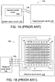
- FIG. 1A schematically illustrates the architecture of a resistive touch screen system.
- the resistive touch screen system 100 comprises a resistive touch panel 110 and a system circuit board 120.
- a resistive panel driver 124 is installed on the system circuit board 120.
- the resistive panel driver 124 is connected with the resistive touch panel 110 through a flexible cable or wires 126.
- a processor, a graphic circuit, a peripheral circuit or any other appropriate circuit is installed on the system circuit board 120.
- the resistive panel driver 124 issues a scan signal to the resistive touch panel 110.
- the resistive touch panel 110 When a finger of the user touches the resistive touch panel 110 to generate a touch point on the resistive touch panel 110, the resistive touch panel 110 generates an analog voltage according to the action of the scan signal.
- the analog signal is transmitted to the resistive panel driver 124 through the flexible cable or wires 126.
- the resistive panel driver 124 calculates the position of the touch point. Moreover, the information about the position of the touch point is transmitted to the rear-end circuit such as the processor, and the subsequent processing operation is performed accordingly.
- FIG. 1B is a schematic circuit diagram of the resistive touch screen system of FIG. 1A .
- the resistive touch screen system 100 comprises the resistive touch panel 110 and the resistive panel driver 124.
- the resistive panel driver 124 is in communication with the resistive touch panel 110 through the flexible cable or wires 126.
- the resistive panel driver 124 is installed on a system circuit board (not shown).
- a four-wire resistive touch panel will be taken as an example for illustration. The operating principles of the five-wire resistive touch panel or the eight-wire resistive touch panel are similar.
- the four electrodes includes a negative Y electrode (Y-), a positive Y electrode (Y+), a negative X electrode (X-) and a positive X electrode (X+).
- plural indium tin oxide (ITO) strips 112 are arranged along a vertical direction. Two ends of each ITO strips 112 are connected with the negative Y electrode (Y-) and the positive Y electrode (Y+), respectively.
- plural ITO strips 114 are arranged along a horizontal direction. Two ends of each ITO strips 114 are connected with the negative X electrode (X-) and the positive X electrode (X+), respectively.
- the resistive panel driver 124 is connected with the negative Y electrode (Y-), the positive Y electrode (Y+), the negative X electrode (X-) and the positive X electrode (X+) through a Y- wire, a Y+ wire, an X- wire and an X+ wire of the flexible cable or wires 126, respectively.
- the ITO strips 112 along the vertical direction and the ITO strips 114 along the horizontal direction are not contacted with each other.
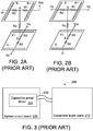
- FIG. 2A is a schematic circuit diagram illustrating an approach of calculating the horizontal position of the touch point by the resistive touch screen system.
- the touch point A is generated when the ITO strip along the vertical direction and the ITO strip along the horizontal direction are contacted with each other. Meanwhile, a contact resistance between the ITO strip along the vertical direction and the ITO strip along the horizontal direction is Rz.
- the resistive panel driver 124 While the resistive panel driver 124 performs a scan action along the horizontal direction (i.e., the X direction), the resistive panel driver 124 provides a power supply voltage Vcc and a ground voltage as a driving signal to the positive X electrode (X+) and the negative X electrode (X-) for performing the scan action along the horizontal direction. That is, the power supply voltage Vcc is connected with the positive X electrode (X+), the ground voltage is connected with the negative X electrode (X-), both positive and negative Y electrodes (Y+,Y-) are used as output terminals to receive a horizontal analog voltage Vx.
- the horizontal analog voltage Vx is determined according to the position of the touch point A. As the touch point A is closer to the right side, the horizontal analog voltage Vx is higher. Whereas, as the touch point A is closer to the left side, the horizontal analog voltage Vx is lower. Consequently, the horizontal analog voltage Vx can be converted into the horizontal position of the touch point A by the resistive panel driver 124.
- the resistive panel driver 124 may perform an analog-to-digital conversion of the horizontal analog voltage Vx in order to acquire the horizontal position of the touch point A.
- FIG. 2B is a schematic circuit diagram illustrating an approach of calculating the vertical position of the touch point by the resistive touch screen system.
- the resistive panel driver 124 While the resistive panel driver 124 performs a scan action along the vertical direction (i.e., the Y direction), the resistive panel driver 124 provides a power supply voltage Vcc and a ground voltage as a driving signal to the positive Y electrode (Y+) and the negative Y electrode (Y-) for performing the scan action along the vertical direction. That is, the power supply voltage Vcc is connected with the positive Y electrode (Y+), the ground voltage is connected with the negative Y electrode (Y-), both positive and negative X electrodes (X+,X-) are used as output terminals to receive a vertical analog voltage Vy.
- the vertical analog voltage Vy is determined according to the position of the touch point A. As the touch point A is closer to the top side, the vertical analog voltage Vy is higher. Whereas, as the touch point A is closer to the left side, the vertical analog voltage Vy is lower. Consequently, the vertical analog voltage Vy can be converted into the vertical position of the touch point A by the resistive panel driver 124.
- the resistive panel driver 124 may perform an analog-to-digital conversion of the vertical analog voltage Vy in order to acquire the vertical position of the touch point A.
- the resistive panel driver 124 performs the scan action along the horizontal direction (i.e., the X direction) to calculate the horizontal position of the touch point according to the horizontal analog voltage Vx, and the resistive panel driver 124 performs a scan action along the vertical direction (i.e., the Y direction) to calculate the vertical position of the touch point according to the vertical analog voltage Vy. After the horizontal position of the touch point and the vertical position of the touch point are combined together, the position of the touch point on the resistive touch panel 110 is realized.
- FIG. 3 schematically illustrates the architecture of a capacitive touch screen system.
- the capacitive touch screen system 200 comprises a capacitive touch panel 210 and a system circuit board 220.
- a capacitive panel driver 224 is build-in on the capacitive panel 210 or installed on the system circuit board 220.
- the capacitive panel driver 224 is connected with the capacitive touch panel 210 through a flexible cable or wires 226.
- a processor, a graphic circuit, a peripheral circuit or any other appropriate circuit is installed on the system circuit board 220.
- the capacitive touch panel driver 224 detects the capacitance change of the touch point and realizes the position of the touch point. Then, the capacitive touch panel driver 224 generates a digital signal indicating the information about the position of the touch point (e.g., the coordinate of the touch point) to the capacitive panel driver 224 through the flexible cable or wires 226. After the digital signal is received by the capacitive panel driver 224, the information about the position of the touch point is transmitted to the rear-end circuit such as the processor, and the subsequent processing operation is performed accordingly.
- the touch point position information which is generated by the capacitive touch panel 210 and transmitted to the capacitive panel driver 224, is digital information.
- the architecture of the resistive touch screen system 100 and the architecture of the capacitive touch screen system 200 are similar. However, the operating principles and methods of detecting the touch point are distinguished. For example, if the resistive panel driver 124 is connected with the capacitive touch panel 210 or the capacitive panel driver 224 is connected with the resistive touch panel 110, the touch screen system cannot be normally operated.
- the manufacturer of the electronic device has to determine which of the resistive touch screen system 100 and the capacitive touch screen system 200 is used.
- the resistive panel driver 124 and the resistive touch panel 110 are purchased and installed in the electronic device.
- the capacitive panel driver 224 and the capacitive touch panel 210 are purchased and installed in the electronic device.
- An embodiment of the present invention provides a touch screen system.
- the touch screen system includes a capacitive touch panel, a system circuit board and a conversion circuit.
- the capacitive touch panel provides a touch point position information.
- a resistive panel driver is installed on the system circuit board.
- the conversion circuit is connected with the capacitive touch panel and the resistive panel driver.
- the touch point position information is converted into a horizontal analog voltage and a vertical analog voltage by the conversion circuit, and the horizontal analog voltage and the vertical analog voltage are transmitted to the resistive panel driver by the conversion circuit.
- Another embodiment of the present invention provides a converting method for a touch screen system including a capacitive touch panel and a resistive panel driver.
- the converting method includes the following steps. Firstly, a touch point position information from the capacitive touch panel is received. when the resistive panel driver performs a scan action along a first direction, a first position information of the touch point position information is converted into a first analog voltage and the first analog voltage is transmitted to the resistive panel driver. When the resistive panel driver performs a scan action along a second direction, a second position information of the touch point position information is converted into a second analog voltage and the second analog voltage is transmitted to the resistive panel driver.
- the electronic device After the electronic device is produced and before the industrial electronic device leaves the factory, the electronic device has to undergo a series of complex product verification processes. After the electronic device passes the test of the product verification processes, the manufacturer will not modify the hardware circuit of the electronic device.
- the resistive touch screen system of the electronic device is not changed to the capacitive touch screen system. If the manufacturer intends to change the resistive touch screen system to the capacitive touch screen system, the resistive panel driver of the system circuit board has to be replaced by a capacitive panel driver and the firmware of the electronic device has to be modified. Before the electronic device leaves the factory, the complex product verification processes should be performed again. Even if the capacitive touch screen system has superior performance, the manufacturer of the electronic device will not install the capacitive touch screen system in the electronic device.
- the present invention provides a touch screen system and a converting method thereof.
- the touch screen system has a conversion circuit.
- the conversion circuit By the conversion circuit, the touch point position information from a capacitive touch panel is converted into analog voltages.
- the analog voltages are transmitted to a resistive panel driver.
- the resistive touch panel of the resistive touch screen system of the electronic device can be directly replaced by the capacitive touch panel. More especially, it is not necessary to modify the system circuit board and the firmware of the electronic device.
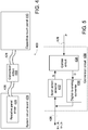
- FIG. 4 schematically illustrates the architecture of a touch screen system according to an embodiment of the present invention.
- the touch screen system 400 comprises a capacitive touch panel 410, a conversion circuit 430 and a system circuit board 420.
- a resistive panel driver 424 is installed on the system circuit board 420.
- the resistive panel driver 424 is connected with a first end of the conversion circuit 430 through a first flexible cable or wires 426.
- a second end of the conversion circuit 430 is connected with the capacitive touch panel 410 through a second flexible cable or wires 428.
- a processor, a graphic circuit, a peripheral circuit or any other appropriate circuit is installed on the system circuit board 420.
- the capacitive touch panel 410 When a finger of the user touches the capacitive touch panel 410 to generate a touch point on the capacitive touch panel 410, the capacitive touch panel 410 generates a digital touch point position information (e.g., a touch point coordinate) to the conversion circuit 430.
- a scan action along a horizontal direction also referred as a horizontal scan action
- the conversion circuit 430 When a scan action along a horizontal direction (also referred as a horizontal scan action) is performed according to a scan signal from the resistive panel driver 424, the conversion circuit 430 generates a horizontal analog voltage Vx to the resistive panel driver 424 according to the digital touch point position information.
- the conversion circuit 430 when a scan action along a vertical direction (also referred as a vertical scan action) is performed according to the scan signal from the resistive panel driver 424, the conversion circuit 430 generates a vertical analog voltage Vy to the resistive panel driver 424 according to the digital touch point position information.
- the resistive panel driver 424 calculates the position of the touch point on the capacitive touch panel 410. Moreover, the touch point position information is transmitted to the rear-end circuit such as the processor, and the subsequent processing operation is performed accordingly.
- FIG. 5 is a schematic circuit diagram illustrating the conversion circuit of the touch screen system according to the embodiment of the present invention.
- the conversion circuit 430 comprises a scan action detector 432, a control circuit 434 and a digital-to-analog converter (DAC) 436.
- DAC digital-to-analog converter
- the scan action detector 432 is connected with the resistive panel driver 424 through a Y- wire, a Y+ wire, an X- wire and an X+ wire of the flexible cable or wires 226. Moreover, the scan action detector 432 recognizes the scan action of the resistive panel driver 424 according to a driving signal from the Y- wire, the Y+ wire, the X- wire and the X+ wire.
- the scan action detector 432 judges that the resistive panel driver 424 performs the scan action along a horizontal direction (i.e., the X direction). Meanwhile, the scan action detector 432 generates a notification signal S to the control circuit 434 to notify the control circuit 434 that the resistive panel driver 424 performs the scan action along the horizontal direction (i.e., the X direction).
- the scan action detector 432 judges that the resistive panel driver 424 performs the scan action along a vertical direction (i.e., the Y direction). Meanwhile, the scan action detector 432 generates a notification signal S to the control circuit 434 to notify the control circuit 434 that the resistive panel driver 424 performs the scan action along the vertical direction (i.e., the Y direction).
- the control circuit 434 is connected with the scan action detector 432, the digital-to-analog converter 436 and the capacitive touch panel 410.
- the capacitive touch panel 410 When a finger of the user touches the capacitive touch panel 410 to generate a touch point on the capacitive touch panel 410, the capacitive touch panel 410 generates the digital touch point position information P (e.g., a touch point coordinate) to the control circuit 434.
- P e.g., a touch point coordinate
- the control circuit 434 After the notification signal S is received by the control circuit 434, the control circuit 434 generates a digital position signal D to the digital-to-analog converter 436.
- the digital position signal D is converted into an analog voltage by the digital-to-analog converter 436.
- the analog voltage is transmitted to the resistive panel driver 424.
- the control circuit 434 acquires the horizontal position information (e.g., the horizontal position of the touch point coordinate) of the digital touch point position information P and generates the digital position signal D to the digital-to-analog converter 436.
- the horizontal analog voltage Vx from the digital-to-analog converter 436 is transmitted to the resistive panel driver 424 through the Y+ or Y- wire.
- the control circuit 434 acquires the vertical position information (e.g., the vertical position of the touch point coordinate) of the digital touch point position information P and generates the digital position signal D to the digital-to-analog converter 436.
- the vertical analog voltage Vy from the digital-to-analog converter 436 is transmitted to the resistive panel driver 424 through the X+ or X- wire.
- the resistive panel driver 424 calculates the position of the touch point according to the horizontal analog voltage Vx and the vertical analog voltage Vy. Moreover, the touch point position information is transmitted to the rear-end circuit such as the processor, and the subsequent processing operation is performed accordingly.
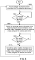
- FIG. 6 is a flowchart illustrating a converting method for a touch screen system according to an embodiment of the present invention.
- the conversion circuit 430 receives a digital touch point position information P from the capacitive touch panel 410 (Step S602). If a scan action along a horizontal direction is detected (Step S604), the horizontal position information of the digital touch point position information P is converted into a horizontal analog voltage Vx and the horizontal analog voltage Vx is transmitted to the resistive panel driver 424 (Step S606). Then, if a scan action along a vertical direction is detected (Step S608), the vertical position information of the digital touch point position information P is converted into a vertical analog voltage Vy and the vertical analog voltage Vy is transmitted to the resistive panel driver 424 (Step S610). Then, the step S602 is repeatedly done to receive the next digital touch point position information.
- the resistive panel driver 424 calculates the position of the touch point according to the horizontal analog voltage Vx and the vertical analog voltage Vy. Moreover, the touch point position information is transmitted to the rear-end circuit such as the processor, and the subsequent processing operation is performed accordingly.
- the present invention provides the touch screen system and the converting method for the touch screen system.
- the conversion circuit 430 and the capacitive touch panel 410 are used to achieve the function of a resistive touch panel.
- the resistive touch panel of the resistive touch screen system of the electronic device can be directly replaced by the capacitive touch panel. More especially, it is not necessary to modify the system circuit board and the firmware of the electronic device. Also, the electronic device with a replaced capacitive panel is not necessary to perform the complex product verification processes again.
- the conversion circuit 430 is integrated into the capacitive touch panel 410 or the system circuit board 420. It is noted that the sequence of performing the scan action is not restricted. For example, in another embodiment, the scan action along the horizontal direction is performed after the scan action along the vertical direction is performed.
Landscapes
- Engineering & Computer Science (AREA)
- General Engineering & Computer Science (AREA)
- Theoretical Computer Science (AREA)
- Human Computer Interaction (AREA)
- Physics & Mathematics (AREA)
- General Physics & Mathematics (AREA)
- Position Input By Displaying (AREA)
Priority Applications (1)
| Application Number | Priority Date | Filing Date | Title |
|---|---|---|---|
| EP16206680.7A EP3340020A1 (fr) | 2016-12-23 | 2016-12-23 | Système d'écran tactile et son procédé de conversion |
Applications Claiming Priority (1)
| Application Number | Priority Date | Filing Date | Title |
|---|---|---|---|
| EP16206680.7A EP3340020A1 (fr) | 2016-12-23 | 2016-12-23 | Système d'écran tactile et son procédé de conversion |
Publications (1)
| Publication Number | Publication Date |
|---|---|
| EP3340020A1 true EP3340020A1 (fr) | 2018-06-27 |
Family
ID=57680124
Family Applications (1)
| Application Number | Title | Priority Date | Filing Date |
|---|---|---|---|
| EP16206680.7A Withdrawn EP3340020A1 (fr) | 2016-12-23 | 2016-12-23 | Système d'écran tactile et son procédé de conversion |
Country Status (1)
| Country | Link |
|---|---|
| EP (1) | EP3340020A1 (fr) |
Cited By (2)
| Publication number | Priority date | Publication date | Assignee | Title |
|---|---|---|---|---|
| WO2021163966A1 (fr) * | 2020-02-20 | 2021-08-26 | 京东方科技集团股份有限公司 | Substrat tactile, module tactile et dispositif d'affichage tactile |
| CN118466792A (zh) * | 2024-06-05 | 2024-08-09 | 淄博乐宸自控技术有限公司 | 一种工业防爆用电容触摸屏装置及其转接电路 |
Citations (7)
| Publication number | Priority date | Publication date | Assignee | Title |
|---|---|---|---|---|
| US20090309852A1 (en) * | 2008-06-13 | 2009-12-17 | Asustek Computer Inc. | Touch panel input device and control method thereof |
| US20100110040A1 (en) * | 2008-10-30 | 2010-05-06 | Samsung Electronics Co., Ltd. | Touch controller having increased sensing sensitivity, and display driving circuit and display device and system having the touch controller |
| US20100117983A1 (en) * | 2008-11-10 | 2010-05-13 | Asustek Computer Inc. | Resistive touch panel and method for detecting touch points thereof |
| EP2194453A1 (fr) * | 2008-11-28 | 2010-06-09 | HTC Corporation | Dispositif électronique portable et son procédé de réveil en mode veille par l'intermédiaire d'un écran tactile |
| US20130100068A1 (en) * | 2011-10-21 | 2013-04-25 | Samsung Electro-Mechanics Co., Ltd. | Touch input sensing device and method thereof |
| US20130127773A1 (en) * | 2011-11-21 | 2013-05-23 | Samsung Electro-Mechanics Co., Ltd. | Touch sensing apparatus and method thereof |
| US20130234980A1 (en) * | 2012-03-06 | 2013-09-12 | Nuvoton Technology Corporation | Touch Sensing Apparatus and Method |
-
2016
- 2016-12-23 EP EP16206680.7A patent/EP3340020A1/fr not_active Withdrawn
Patent Citations (7)
| Publication number | Priority date | Publication date | Assignee | Title |
|---|---|---|---|---|
| US20090309852A1 (en) * | 2008-06-13 | 2009-12-17 | Asustek Computer Inc. | Touch panel input device and control method thereof |
| US20100110040A1 (en) * | 2008-10-30 | 2010-05-06 | Samsung Electronics Co., Ltd. | Touch controller having increased sensing sensitivity, and display driving circuit and display device and system having the touch controller |
| US20100117983A1 (en) * | 2008-11-10 | 2010-05-13 | Asustek Computer Inc. | Resistive touch panel and method for detecting touch points thereof |
| EP2194453A1 (fr) * | 2008-11-28 | 2010-06-09 | HTC Corporation | Dispositif électronique portable et son procédé de réveil en mode veille par l'intermédiaire d'un écran tactile |
| US20130100068A1 (en) * | 2011-10-21 | 2013-04-25 | Samsung Electro-Mechanics Co., Ltd. | Touch input sensing device and method thereof |
| US20130127773A1 (en) * | 2011-11-21 | 2013-05-23 | Samsung Electro-Mechanics Co., Ltd. | Touch sensing apparatus and method thereof |
| US20130234980A1 (en) * | 2012-03-06 | 2013-09-12 | Nuvoton Technology Corporation | Touch Sensing Apparatus and Method |
Cited By (2)
| Publication number | Priority date | Publication date | Assignee | Title |
|---|---|---|---|---|
| WO2021163966A1 (fr) * | 2020-02-20 | 2021-08-26 | 京东方科技集团股份有限公司 | Substrat tactile, module tactile et dispositif d'affichage tactile |
| CN118466792A (zh) * | 2024-06-05 | 2024-08-09 | 淄博乐宸自控技术有限公司 | 一种工业防爆用电容触摸屏装置及其转接电路 |
Similar Documents
| Publication | Publication Date | Title |
|---|---|---|
| US10095365B2 (en) | Position detecting method for touchscreen panel, touchscreen panel, and electronic apparatus | |
| US10120506B2 (en) | Multi-touch capacitive sensing surface | |
| EP3144790B1 (fr) | Panneau et circuit de détection tactiles | |
| US9323382B2 (en) | Information terminal device and touch coordinate determination method | |
| CN106257387B (zh) | 触摸屏控制器、触摸感测设备和触摸感测方法 | |
| US7105752B2 (en) | Method and apparatus for avoiding pressing inaccuracies on a touch panel | |
| US20090251422A1 (en) | Method and system for enhancing interaction of a virtual keyboard provided through a small touch screen | |
| JP2010055612A (ja) | 多点タッチセンサーシステム | |
| KR20140010859A (ko) | 고속 패널 스캐닝을 위한 이득 정정 | |
| JP2010055613A (ja) | 多点タッチセンサーシステムのオペレーション方法 | |
| CN102207781A (zh) | 具有改进分辨率的触摸输入装置 | |
| US11353978B2 (en) | Method and apparatus for determining a touch point | |
| CN108475137A (zh) | 使用混合估计方法减轻共模显示噪声 | |
| US9176631B2 (en) | Touch-and-play input device and operating method thereof | |
| EP3340020A1 (fr) | Système d'écran tactile et son procédé de conversion | |
| CN115061597B (zh) | 触控显示模组和电子设备 | |
| CN107357747A (zh) | 一种外接设备接口的识别方法及移动终端 | |
| TWI394068B (zh) | 感測結構及包含該感測結構之顯示器 | |
| CN102346615B (zh) | 电阻/电容混合式触控装置及触控装置的驱动方法 | |
| US20150070296A1 (en) | Touch panel and method of using the same | |
| US20110242016A1 (en) | Touch screen | |
| CN213545249U (zh) | 一种电容式压力触控装置 | |
| KR20040042146A (ko) | 다중 터치패널의 구동방법, 구동장치 및 그를 사용한 다중터치패널 장치 | |
| JP2001043003A (ja) | タッチパネル入力装置 | |
| US11163402B1 (en) | Mutual capacitive touch sensing anomaly detection |
Legal Events
| Date | Code | Title | Description |
|---|---|---|---|
| PUAI | Public reference made under article 153(3) epc to a published international application that has entered the european phase |
Free format text: ORIGINAL CODE: 0009012 |
|
| AK | Designated contracting states |
Kind code of ref document: A1 Designated state(s): AL AT BE BG CH CY CZ DE DK EE ES FI FR GB GR HR HU IE IS IT LI LT LU LV MC MK MT NL NO PL PT RO RS SE SI SK SM TR |
|
| AX | Request for extension of the european patent |
Extension state: BA ME |
|
| STAA | Information on the status of an ep patent application or granted ep patent |
Free format text: STATUS: THE APPLICATION IS DEEMED TO BE WITHDRAWN |
|
| 18D | Application deemed to be withdrawn |
Effective date: 20190103 |