EP3340031B1 - Circuits de détection de mouvement et procédés associés - Google Patents
Circuits de détection de mouvement et procédés associés Download PDFInfo
- Publication number
- EP3340031B1 EP3340031B1 EP16205907.5A EP16205907A EP3340031B1 EP 3340031 B1 EP3340031 B1 EP 3340031B1 EP 16205907 A EP16205907 A EP 16205907A EP 3340031 B1 EP3340031 B1 EP 3340031B1
- Authority
- EP
- European Patent Office
- Prior art keywords
- signal
- motion
- audio
- tap
- output
- Prior art date
- Legal status (The legal status is an assumption and is not a legal conclusion. Google has not performed a legal analysis and makes no representation as to the accuracy of the status listed.)
- Not-in-force
Links
Images
Classifications
-
- G—PHYSICS
- G06—COMPUTING OR CALCULATING; COUNTING
- G06F—ELECTRIC DIGITAL DATA PROCESSING
- G06F1/00—Details not covered by groups G06F3/00 - G06F13/00 and G06F21/00
- G06F1/16—Constructional details or arrangements
- G06F1/1613—Constructional details or arrangements for portable computers
- G06F1/1633—Constructional details or arrangements of portable computers not specific to the type of enclosures covered by groups G06F1/1615 - G06F1/1626
- G06F1/1684—Constructional details or arrangements related to integrated I/O peripherals not covered by groups G06F1/1635 - G06F1/1675
- G06F1/1694—Constructional details or arrangements related to integrated I/O peripherals not covered by groups G06F1/1635 - G06F1/1675 the I/O peripheral being a single or a set of motion sensors for pointer control or gesture input obtained by sensing movements of the portable computer
-
- G—PHYSICS
- G06—COMPUTING OR CALCULATING; COUNTING
- G06F—ELECTRIC DIGITAL DATA PROCESSING
- G06F3/00—Input arrangements for transferring data to be processed into a form capable of being handled by the computer; Output arrangements for transferring data from processing unit to output unit, e.g. interface arrangements
- G06F3/16—Sound input; Sound output
- G06F3/165—Management of the audio stream, e.g. setting of volume, audio stream path
-
- G—PHYSICS
- G06—COMPUTING OR CALCULATING; COUNTING
- G06F—ELECTRIC DIGITAL DATA PROCESSING
- G06F1/00—Details not covered by groups G06F3/00 - G06F13/00 and G06F21/00
- G06F1/16—Constructional details or arrangements
- G06F1/1613—Constructional details or arrangements for portable computers
- G06F1/1626—Constructional details or arrangements for portable computers with a single-body enclosure integrating a flat display, e.g. Personal Digital Assistants [PDAs]
-
- G—PHYSICS
- G06—COMPUTING OR CALCULATING; COUNTING
- G06F—ELECTRIC DIGITAL DATA PROCESSING
- G06F1/00—Details not covered by groups G06F3/00 - G06F13/00 and G06F21/00
- G06F1/16—Constructional details or arrangements
- G06F1/1613—Constructional details or arrangements for portable computers
- G06F1/1633—Constructional details or arrangements of portable computers not specific to the type of enclosures covered by groups G06F1/1615 - G06F1/1626
- G06F1/1684—Constructional details or arrangements related to integrated I/O peripherals not covered by groups G06F1/1635 - G06F1/1675
-
- G—PHYSICS
- G06—COMPUTING OR CALCULATING; COUNTING
- G06F—ELECTRIC DIGITAL DATA PROCESSING
- G06F1/00—Details not covered by groups G06F3/00 - G06F13/00 and G06F21/00
- G06F1/16—Constructional details or arrangements
- G06F1/1613—Constructional details or arrangements for portable computers
- G06F1/1633—Constructional details or arrangements of portable computers not specific to the type of enclosures covered by groups G06F1/1615 - G06F1/1626
- G06F1/1684—Constructional details or arrangements related to integrated I/O peripherals not covered by groups G06F1/1635 - G06F1/1675
- G06F1/1688—Constructional details or arrangements related to integrated I/O peripherals not covered by groups G06F1/1635 - G06F1/1675 the I/O peripheral being integrated loudspeakers
-
- G—PHYSICS
- G06—COMPUTING OR CALCULATING; COUNTING
- G06F—ELECTRIC DIGITAL DATA PROCESSING
- G06F3/00—Input arrangements for transferring data to be processed into a form capable of being handled by the computer; Output arrangements for transferring data from processing unit to output unit, e.g. interface arrangements
- G06F3/01—Input arrangements or combined input and output arrangements for interaction between user and computer
- G06F3/017—Gesture based interaction, e.g. based on a set of recognized hand gestures
-
- G—PHYSICS
- G06—COMPUTING OR CALCULATING; COUNTING
- G06F—ELECTRIC DIGITAL DATA PROCESSING
- G06F3/00—Input arrangements for transferring data to be processed into a form capable of being handled by the computer; Output arrangements for transferring data from processing unit to output unit, e.g. interface arrangements
- G06F3/01—Input arrangements or combined input and output arrangements for interaction between user and computer
- G06F3/048—Interaction techniques based on graphical user interfaces [GUI]
- G06F3/0487—Interaction techniques based on graphical user interfaces [GUI] using specific features provided by the input device, e.g. functions controlled by the rotation of a mouse with dual sensing arrangements, or of the nature of the input device, e.g. tap gestures based on pressure sensed by a digitiser
-
- G—PHYSICS
- G06—COMPUTING OR CALCULATING; COUNTING
- G06F—ELECTRIC DIGITAL DATA PROCESSING
- G06F3/00—Input arrangements for transferring data to be processed into a form capable of being handled by the computer; Output arrangements for transferring data from processing unit to output unit, e.g. interface arrangements
- G06F3/01—Input arrangements or combined input and output arrangements for interaction between user and computer
- G06F3/048—Interaction techniques based on graphical user interfaces [GUI]
- G06F3/0487—Interaction techniques based on graphical user interfaces [GUI] using specific features provided by the input device, e.g. functions controlled by the rotation of a mouse with dual sensing arrangements, or of the nature of the input device, e.g. tap gestures based on pressure sensed by a digitiser
- G06F3/0488—Interaction techniques based on graphical user interfaces [GUI] using specific features provided by the input device, e.g. functions controlled by the rotation of a mouse with dual sensing arrangements, or of the nature of the input device, e.g. tap gestures based on pressure sensed by a digitiser using a touch-screen or digitiser, e.g. input of commands through traced gestures
-
- G—PHYSICS
- G06—COMPUTING OR CALCULATING; COUNTING
- G06F—ELECTRIC DIGITAL DATA PROCESSING
- G06F3/00—Input arrangements for transferring data to be processed into a form capable of being handled by the computer; Output arrangements for transferring data from processing unit to output unit, e.g. interface arrangements
- G06F3/16—Sound input; Sound output
- G06F3/167—Audio in a user interface, e.g. using voice commands for navigating, audio feedback
-
- G—PHYSICS
- G06—COMPUTING OR CALCULATING; COUNTING
- G06F—ELECTRIC DIGITAL DATA PROCESSING
- G06F2200/00—Indexing scheme relating to G06F1/04 - G06F1/32
- G06F2200/16—Indexing scheme relating to G06F1/16 - G06F1/18
- G06F2200/163—Indexing scheme relating to constructional details of the computer
- G06F2200/1636—Sensing arrangement for detection of a tap gesture on the housing
-
- G—PHYSICS
- G06—COMPUTING OR CALCULATING; COUNTING
- G06F—ELECTRIC DIGITAL DATA PROCESSING
- G06F2200/00—Indexing scheme relating to G06F1/04 - G06F1/32
- G06F2200/16—Indexing scheme relating to G06F1/16 - G06F1/18
- G06F2200/163—Indexing scheme relating to constructional details of the computer
- G06F2200/1637—Sensing arrangement for detection of housing movement or orientation, e.g. for controlling scrolling or cursor movement on the display of an handheld computer
-
- H—ELECTRICITY
- H04—ELECTRIC COMMUNICATION TECHNIQUE
- H04R—LOUDSPEAKERS, MICROPHONES, GRAMOPHONE PICK-UPS OR LIKE ACOUSTIC ELECTROMECHANICAL TRANSDUCERS; ELECTRIC HEARING AIDS; PUBLIC ADDRESS SYSTEMS
- H04R2400/00—Loudspeakers
- H04R2400/01—Transducers used as a loudspeaker to generate sound aswell as a microphone to detect sound
Definitions
- the present disclosure relates to motion detection circuits, including tap-detection-circuits, and associated methods.
- Such motion detection circuits can be used to detect a tap (for example a short touch) on an electronic device, such as the touch screen of a smartphone.
- the digital-audio-processor is configured to provide an audio-input-signal that is representative of a failsafe mode of operation of the audio-output-module.
- the digital-motion-detector is configured to disable the programmable-gain-amplifier if the state of the prelim-motion-detected-signal is representative of "no-potential-motion-detected".
- the motion-detection-circuit further comprises an audio-output-module configured to: receive the audio-input-signal from the digital-audio-processor; and provide the audio-output-signal to the audio-output-receiver.
- the motion-detection-circuit further comprises a motion-signal-receiver-module configured to provide the received-motion-signal to the motion-signal-receiver-terminal.
- the motion-signal-receiver-module is a speaker that is operable as a microphone, a vibrator or an accelerometer.
- tap-detection-circuit comprising any motion-detection-circuit disclosed herein.
- an electronic device such as a mobile telephone or smart phone, that includes any motion-detection-circuit disclosed herein.
- Motion detection circuits can process sounds in order to detect motion. For example, a tap (short touch) on or near a device, such as on the touchscreen of a device, can be detected by processing the associated sound that is received at a microphone. This can be referred to as tap detection. The following description will be in relation to detecting taps. However, it will be appreciated that the tap detection functionality can be equally applied more generally to motion sensing / detection.
- Devices that can have tap detection during audio playback can be advantageous in that uniform usage of a tap feature can be provided to a user. For instance, a tap can be used to wake up a device or to activate a display screen irrespective of whether or not audio is being played back.
- Such devices can include portable electronics devices such as mobile phones, smartphones, tablet computers, laptop computers, etc.
- such tap detection can be provided for a system that has two speakers, such as a hands-free-speaker and a receiver-speaker.
- the receiver-speaker can be used for tap detection.
- tap detection makes use of the receiver-speaker as a microphone (speaker-as-a-microphone; SAM), and can be an efficient method of detecting a tap in terms of power consumption.
- SAM can advantageously make use of an existing analogue to digital converter (ADC) that is also used as part of a circuit that provides the audio playback from the other speaker.
- ADC analogue to digital converter
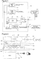
- Figure 1 shows an example embodiment of a motion-detection-circuit, which in this example is a tap-detection-circuit 100, that includes a digital-audio-processor 102 that provides an audio-input-signal to an audio-output-module 104.
- the audio-output-module 104 when in use, provides an audio-output-signal based on the audio-input-signal.
- the audio-output-signal is provided as feedback to an audio-output-receiver 105 of the tap-detection-circuit 100.
- the audio-output-receiver 105 may simply be an internal connection within an integrated circuit, or may be a connection to a component that is external to the integrated circuit.
- the audio-output-signal can be any signal that is representative of audio playback that is to be provided by a speaker (not shown).
- the audio-output-signal can be representative of a signal that is provided to the speaker by an amplifier (not shown) in the audio-output-module 104, such that the speaker outputs music or a person's voice as part of a telephone conversation.
- the audio-output-signal is provided as feedback to the digital-audio-processor 102, via a switch 108 and an ADC 106.
- Such feedback can be used by the digital-audio-processor 102 to control the audio-input-signal such that the speaker is protected from damage.
- the ADC 106 can provide information about the output current of the audio-output-module to a speaker protection algorithm running on the digital-audio-processor 102.
- speaker protection algorithms are known in the art, and can include a SpeakerBoost algorithm.
- the circuit of Figure 1 also includes a motion-signal-receiver-terminal that receives a received-motion-signal, which in this example is a tap-signal-receiver-terminal 107 that receives a received-tap-signal from a tap-signal-receiver-module 110.
- the tap-signal-receiver-module 110 is an example of a motion-signal-receiver-module.
- the tap-signal-receiver-terminal 107 may simply be an internal connection within an integrated circuit, or may be a connection to a component that is external to the integrated circuit.
- the tap-signal-receiver-module 110 can include a speaker that is not actively being used to provide audio output. For example, if a hands-free-speaker is being controlled to provide audio output by the audio-output-module 104, then a receiver-speaker can be used as a microphone to provide the functionality of the tap-signal-receiver-module 110. That is, the received-tap-signal can be a microphone-signal provided by the receiver-speaker.
- a preliminary-motion-detector which in this example is a preliminary-tap-detector 112, processes the received-tap-signal in order to set a state of a prelim-tap-detected-signal based on the received-tap-signal.
- the preliminary-tap-detector 112 processes the received-tap-signal in the analogue domain in order to make a preliminary decision as to whether or not the received-tap-signal is likely to be indicative of a tap.
- the state of the prelim-tap-detected-signal can be set as representative of "potential-tap-detected", which is indicative of a detected tap; or can be set as representative of "no-potential-tap-detected", which is indicative of no detected tap.
- This processing in the analogue domain may not be considered reliable enough to take the responsive action that should be performed if a tap has been detected (for example to activate a display screen), yet it may be considered reliable enough to initiate digital processing of the received-tap-signal to make a more reliable decision as to whether or not a tap has occurred.
- Such analogue-tap-detection-algorithms are known in the art, for example from patent publications US2015/0334477 A1 (NXP B.V.) and US2013/0051567 A1 (Gipson ).
- the prelim-tap-detected-signal is an example of a prelim-motion-detected-signal, which can have a state that is representative of "potential-motion-detected" or "no-potential-motion-detected”.
- Digital processing of the received-tap-signal will require conversion of the received-tap-signal from the analogue to the digital domain.
- the ADC 106 can occupy a relatively large amount of area on a silicon chip, and can also be costly. Therefore, a more efficient and compact integrated circuit can be provided by avoiding a need to include a separate ADC for tap detection.
- the ADC 106 that is used in the feedback path of the audio-output-module 104 can be used to convert the received-tap-signal to the digital domain in response to the detection of a potential tap by the preliminary-tap-detector 112. Such processing can be considered as not having a too detrimental effect on the audio that is provided by the audio-output-module, whilst enabling tap detection without requiring another ADC.
- the received-tap-signal is provided as an input to a digital-tap-detector 114 via the same switch 108 and ADC 106 that were used in the feedback loop for the digital-audio-processor 102.
- This can be considered as a tap-detection-mode of operation.
- the digital-tap-detector 114 is an example of a digital-motion-detector.
- the digital-tap-detector 114 can process the digital representation of the received-tap-signal in order to set a state of a tap-detection-signal.
- the tap-detection-signal can set a flag on an Interrupt line that is provided to an associated host device for associated processing (such as to activate a display screen).
- the tap-detection-signal is an example of a motion-detection-signal.
- the ADC 106 has an ADC-input-terminal 116 and an ADC-output-terminal 118.
- the ADC-output-terminal 118 provides an ADC-output-signal.
- the ADC-output-signal can be representative of either: (i) the audio-output-signal from the audio-output-module 104; or (ii) the received-tap-signal from the tap-signal-receiver-module 110.
- the switch 108 is configured to connect either (i) the audio-output-receiver 105; or (ii) the tap-signal-receiver-terminal 107, to the ADC-input-terminal 116 based on the state of the prelim-tap-detected-signal. If the state of the prelim-tap-detected-signal is "potential-tap-detected", then the switch 108 connects the tap-signal-receiver-terminal 107 to the ADC-input-terminal 116.
- the switch 108 connects the audio-output-receiver 105 to the ADC-input-terminal 116.
- the prelim-tap-detected-signal is used as a control signal for the switch 108 such that the ADC 106 can provide an output signal that is suitable for either: (i) providing feedback from the audio-output-module 104 to the digital-audio-processor 102; or (ii) providing a signal to the digital-tap-detector 114 such that it can determine whether or not a tap has occurred.
- the digital-tap-detector 114 receives the prelim-tap-detected-signal and the ADC-output-signal as input signals, and provides the tap-detection-signal as an output signal.
- the digital-tap-detector 114 is configured to, based on the state of the prelim-tap-detected-signal, process the ADC-output-signal in order to set a state of the tap-detection-signal.
- the digital-tap-detector 114 is configured to only process the ADC-output-signal if the state of the prelim-tap-detected-signal is "potential-tap-detected".
- the state of the tap-detection-signal is set as "no-tap-detected".
- the digital-tap-detector 114 can apply a digital-tap-detection-algorithm to the ADC-output-signal in order to set the state of the tap-detection-signal as either "tap-detected" or "no-tap-detected".
- Such digital-tap-detection-algorithms are known in the art.
- the digital-audio-processor 102 also receives the prelim-tap-detected-signal and the ADC-output-signal as input signals, and provides the audio-input-signal as an output signal.
- the digital-audio-processor 102 is configured to, based on the state of the prelim-tap-detected-signal, process the ADC-output-signal in order to provide an audio-input-signal to the audio-output-module 104. In this example, if the state of the prelim-tap-detected-signal is "potential-tap-detected", then the digital-audio-processor 102 provides an audio-input-signal that is independent of the ADC-output-signal.
- the feedback loop is interrupted and the digital-audio-processor 102 can generate the audio-input-signal without taking any feedback into account.
- the digital-audio-processor 102 can cause the audio-input-module 104 to operate in a failsafe mode of operation if the state of the prelim-tap-detected-signal is "potential-tap-detected". This will mean that the audio-output-module 104 will not benefit from any enhanced processing that can be performed when feedback is used. However, if the audio-input-module 104 operates in the failsafe mode of operation for only a short time (for example a few seconds), then a user may not easily be able identify a degradation in audio quality.
- the digital-audio-processor 102 processes the ADC-output-signal in order to provide an audio-input-signal that is based on the ADC-output-signal. That is, the feedback loop from the audio-output-module 104 to the digital-audio-processor 102 is used such that enhanced audio can be provided by the audio-output-module 104, as discussed above.
- the inputs and optionally the outputs of the ADC can be switched based on an event, which can be detected by a preliminary-tap-detector such as a tap comparator.
- the ADC can therefore be shared asynchronously.
- the speaker / tap algorithms can be notified such that, for example, the speaker algorithm stops accepting incoming data (which can be considered acceptable if it is only for a short time, such as a few seconds) whilst still enabling adequate speaker protection for a short period of time, during which time the tap algorithm can take over. Inquiring of the tap pattern can take few seconds depending on its complexity.
- FIG. 2 shows another example embodiment of a tap-detection-circuit.
- a hands-free-speaker 234 is being used to provide music as audio output.
- a DSP-subsystem provides the functionality of a digital-audio-processor such that it can provide an audio-input-signal to an amplifier 204.
- the amplifier 204 can be considered as providing the functionality of an audio-output-module, in that it provides an audio-output-signal to the hands-free-speaker 234.
- the audio-output-signal is also provided as an input signal to an ADC, in this example a sigma-delta ADC 206.
- the functionality of a switch is embedded within the sigma-delta ADC 206 such that either the audio-output-signal or a received-tap-signal are converted into a digital signal that is provided at the ADC-output-terminal of the sigma-delta-ADC
- the sigma-delta ADC 206 converts the audio-output-signal to the digital domain, and provides an ADC-output-signal to an optional decimator 226.
- the decimator 226 can be used to reduce the sampling rate of a signal, if doing so is beneficial for the subsequent processing that will be performed by the DSP sub-system 220. Use of the decimator 226 can be particularly beneficial where the ADC is a sigma-delta ADC 206. In other examples, where the ADC is not a sigma-delta ADC 206, such as a flash or SAR ADC, the decimator 226 may not be required.
- the DSP sub-system 220 can then process the decimated digital representation of the audio-output-signal when generating the audio-input-signal for the hands-free-speaker 234, such that feedback is used to control the hands-free-speaker 234.
- a receiver-speaker 210 is operated as a microphone, and provides at least part of the functionality of a tap-signal-receiver-module.
- the receiver-speaker 210 is shown as receiving a sound wave from a user tapping an electronic device, in this example a mobile telephone.
- a CODEC 222 is shown as connected to the receiver-speaker 210, for coding and decoding information that is communicated with the receiver-speaker 210 when it is used to provide audio output, which is not the case for the remainder of this description.
- the functionality of the hands-free-speaker 234 and the receiver-speaker 210 can be reversed such that the receiver-speaker 210 is used to provide audio output, and the hands-free-speaker 234 is used as a microphone for detecting taps.
- the receiver-speaker 210 is shown as providing a first input signal to a comparator 230 in a preliminary-tap-detector 212.
- a potential-tap-threshold-signal is provided as a second input signal to the comparator 232 from a level-setting-block 228.
- a controller 232 of the preliminary-tap-detector 212 can set the state of a prelim-tap-detected-signal as "potential-tap-detected" if the received-tap-signal from the receiver-speaker 210 exceeds a potential-tap-threshold-level (which is an example of a potential-motion-threshold-level) that is defined by the potential-tap-threshold-signal.
- the potential-tap-threshold-level can be set at a level that is high enough to result in the comparator 230 not being triggered by the audio output that is provided by the hands-free-speaker 234.
- the controller 232 then provides this prelim-tap-detected-signal (shown as "enable/disable” in Figure 2 ) to the DSP sub-system 220, the sigma-delta ADC 206, the decimator 226, and an optional programmable-gain-amplifier (PGA) 224, as will be discussed below.
- PGA programmable-gain-amplifier
- the operation of the decimator 226 can be controlled based on the "enable/disable” signal as follows.
- the decimator is used to reduce the sampling rate of the signal received at its input in order to provide an output signal to the DSP sub-system 220 for processing as part of the feedback that is used to control the hands-free-speaker 234.
- the decimator in this example is disabled such that the functionality for reducing the sampling rate is bypassed, and the ADC-output-signal is passed to the DSP sub-system 220 without a change in its sampling rate.
- the decimator 226 can still contain audio related data (that is, it can have memory effect). If this audio related data is processed by the tap algorithm on the DSP sub-system 220, then it can reduce the robustness of the tap algorithm. Therefore, bypassing the functionality of the decimator 226 when a potential tap is detected can clear / skip the audio data. In some examples, this can also be achieved by introducing timestamping, such that the DSP sub-system 220 can (in)validate incoming data based on preliminary tap detection.
- the controller 232 can apply filtering to the output signal from the comparator 230 in order to suppress non-tap related peaks.
- the controller 232 can includes a simple counter, which evaluates the comparator output signal for a given time and if the state of the comparator output signal persists for the given time, then the controller tags it as a potential candidate for the further processing by setting a state of the "enable/disable" signal as representative of "potential-tap-detected". In this way, high frequency noise can be suppressed.
- the preliminary-tap-detector 212 When the preliminary-tap-detector 212 does not determine a potential tap, it sets the state of the prelim-tap-detected-signal ("enable/disable” signal in the figure) as "no-potential-tap-detected" such that:
- the preliminary-tap-detector 212 determines a potential tap, it sets the state of the prelim-tap-detected-signal ("enable/disable” signal in the figure) as "potential-tap-detected" such that:
- the preliminary-tap-detector 212 changes the state of the prelim-tap-detected-signal, it should not generate artefacts in the ADC-output-signal, such as overshoots or oscillations / variations in the signal, that can be caused by a DC offset change or by a remaining garbage data. In this way, portions of the ADC-output-signal that correspond to a digital representation of the audio-output-signal should not be processed by the DSP sub-system 220 when applying a digital-tap-detection-algorithm to the ADC-output-signal.
- portions of the ADC-output-signal that correspond to a digital representation of the received-tap-signal should not be processed by an audio-algorithm on the DSP sub-system 220 when generating the audio-input-signal for the hands-free-speaker 234.
- One way in which the system of Figure 2 can address such artefacts is to disable the decimator, as discussed above, in order to reduce the likelihood of undesired memory effects.
- the ADC can has also have a memory effect, although it may be shorter, such as 10 clock cycles.
- timestamping can be used to identify portions of the ADC-output-signal for processing either by the audio-algorithm or the digital-tap-detection-algorithm, based on the time that the state of the "enable/disable" signal changes.
- the unclaimed example embodiment of Figure 2 can advantageously share an ADC resource based on asynchronous events that are identified using a tap comparator 230.
- One or more of the examples disclosed herein can enable an ADC to be used asynchronously to either: (i) provide feedback for audio processing; or (ii) convert a received-tap-signal to the digital domain, such that the digital domain signal can be processed to determine whether or not a tap has been made by a user. In this way, a separate ADC is not required for the tap detection, which would increase the silicon area required to implement the tap detection functionality.
- Such asynchronous operation can be considered to provide advantages over using a (synchronously) multiplexed ADC, because such a multiplexed ADC may require anti-aliasing filters and modifications to an existing ADC that is already used as part of the audio circuit's feedback loop, and also may increase the silicon area required by more than is necessary to implement a simple switch. Furthermore, by continuing to operate the audio circuit whilst tap detection is being performed, optionally in a failsafe mode of operation, it is not necessary to interrupt the audio playback in order for the ADC to be used for tap detection.
- the set of instructions/method steps described above are implemented as functional and software instructions embodied as a set of executable instructions which are effected on a computer or machine which is programmed with and controlled by said executable instructions. Such instructions are loaded for execution on a processor (such as one or more CPUs).
- processor includes microprocessors, microcontrollers, processor modules or subsystems (including one or more microprocessors or microcontrollers), or other control or computing devices.
- a processor can refer to a single component or to plural components.
- the set of instructions/methods illustrated herein and data and instructions associated therewith are stored in respective storage devices, which are implemented as one or more non-transient machine or computer-readable or computer-usable storage media or mediums.
- Such computer-readable or computer usable storage medium or media is (are) considered to be part of an article (or article of manufacture).
- An article or article of manufacture can refer to any manufactured single component or multiple components.
- the non-transient machine or computer usable media or mediums as defined herein excludes signals, but such media or mediums may be capable of receiving and processing information from signals and/or other transient mediums.
- Example embodiments of the material discussed in this specification can be implemented in whole or in part through network, computer, or data based devices and/or services. These may include cloud, internet, intranet, mobile, desktop, processor, look-up table, microcontroller, consumer equipment, infrastructure, or other enabling devices and services.
- one or more instructions or steps discussed herein are automated.
- the terms automated or automatically mean controlled operation of an apparatus, system, and/or process using computers and/or mechanical/electrical devices without the necessity of human intervention, observation, effort and/or decision.
- any components said to be coupled may be coupled or connected either directly or indirectly.
- additional components may be located between the two components that are said to be coupled.
Landscapes
- Engineering & Computer Science (AREA)
- Theoretical Computer Science (AREA)
- General Engineering & Computer Science (AREA)
- Physics & Mathematics (AREA)
- Human Computer Interaction (AREA)
- General Physics & Mathematics (AREA)
- Computer Hardware Design (AREA)
- Multimedia (AREA)
- Health & Medical Sciences (AREA)
- Audiology, Speech & Language Pathology (AREA)
- General Health & Medical Sciences (AREA)
- Compression, Expansion, Code Conversion, And Decoders (AREA)
- Circuit For Audible Band Transducer (AREA)
Claims (7)
- Circuit de détection de mouvement (100) comprenant :un récepteur de sortie audio (105) configuré pour recevoir un signal de sortie audio d'un module de sortie audio (104) ;une borne de récepteur de signal de mouvement (107) configurée pour recevoir un signal de mouvement analogique reçu d'un module de récepteur de signal de mouvement (110) ;un détecteur de mouvement préliminaire (112) comprenant un comparateur (230) configuré pour comparer : (i) un niveau de signal du signal de mouvement reçu avec (ii) un niveau de seuil de mouvement potentiel, et définir un état binaire du signal de mouvement préliminaire détecté sur la base du résultat de la comparaison correspondant soit à « aucun mouvement potentiel détecté » soit à « mouvement potentiel détecté » ;un convertisseur analogique-numérique (106), ADC, ayant :une borne d'entrée ADC (116) ; etune borne de sortie ADC (118) configurée pour fournir un signal de sortie ADC qui est une représentation numérique d'un signal reçu à la borne d'entrée ADC ;un commutateur (108) configuré pour connecter soit :(i) le récepteur de sortie audio (105) à la borne d'entrée ADC (116) si l'état du signal de mouvement préliminaire détecté est représentatif de « aucun mouvement potentiel détecté » ; soit :(ii) la borne de récepteur de signal de mouvement (107) à la borne d'entrée ADC (116) si l'état du signal de mouvement préliminaire détecté est représentatif de « mouvement potentiel détecté » ;un détecteur de mouvement numérique (114) configuré pour traiter le signal de sortie ADC afin d'établir un état d'un signal de détection de mouvement si l'état du signal de mouvement préliminaire détecté est représentatif d'un « mouvement potentiel détecté » ; et un processeur audio numérique (102) configuré pour :fournir un signal d'entrée audio pour le module de sortie audio qui est indépendant du signal de sortie ADC si l'état du signal de mouvement préliminaire détecté est représentatif de « mouvement potentiel détecté » en appliquant un algorithme de traitement de tapotement numérique pour détecter un tapotement comme un mouvement ; ettraiter le signal de sortie ADC comme une rétroaction afin de fournir un signal d'entrée audio amélioré au module de sortie audio qui est basé sur le signal de sortie ADC si l'état du signal de mouvement préliminaire détecté est représentatif de « aucun mouvement potentiel détecté ».
- Circuit de détection de mouvement selon la revendication 1, dans lequel, si l'état du signal de mouvement préliminaire détecté est représentatif d'un « mouvement potentiel détecté », alors le processeur audio numérique est configuré pour fournir un signal d'entrée audio qui est représentatif d'un mode de fonctionnement à sécurité intégrée du module de sortie audio.
- Circuit de détection de mouvement selon l'une quelconque des revendications précédentes, comprenant en outre un amplificateur de gain programmable (224) configuré pour :appliquer un gain au signal de mouvement reçu, etfournir un signal de mouvement reçu amplifié au commutateur, de manière à ce que le commutateur soit configuré pour connecter soit (i) le récepteur de sortie audio, soit (ii) la borne de récepteur de signal de mouvement amplifié à la borne d'entrée ADC sur la base de l'état du signal de mouvement préliminaire détecté.
- Circuit de détection de mouvement selon la revendication 3, dans lequel le détecteur de mouvement numérique est configuré pour désactiver l'amplificateur à gain programmable si l'état du signal de mouvement préliminaire détecté est représentatif de « aucun mouvement potentiel détecté ».
- Circuit de détection de mouvement selon l'une quelconque des revendications précédentes, comprenant en outre un module de sortie audio (104) configuré pour : recevoir le signal d'entrée audio du processeur audio numérique ; et fournir le signal de sortie audio au récepteur de sortie audio.
- Circuit de détection de mouvement selon l'une quelconque des revendications précédentes, dans lequel le module de récepteur de signal de mouvement est un haut-parleur qui peut fonctionner comme un microphone, un vibrateur ou un accéléromètre.
- Dispositif électronique comprenant le circuit de détection de mouvement de l'une quelconque des revendications 1 à 6.
Priority Applications (2)
| Application Number | Priority Date | Filing Date | Title |
|---|---|---|---|
| EP16205907.5A EP3340031B1 (fr) | 2016-12-21 | 2016-12-21 | Circuits de détection de mouvement et procédés associés |
| US15/828,674 US10429906B2 (en) | 2016-12-21 | 2017-12-01 | Motion detection circuits, and associated methods |
Applications Claiming Priority (1)
| Application Number | Priority Date | Filing Date | Title |
|---|---|---|---|
| EP16205907.5A EP3340031B1 (fr) | 2016-12-21 | 2016-12-21 | Circuits de détection de mouvement et procédés associés |
Publications (2)
| Publication Number | Publication Date |
|---|---|
| EP3340031A1 EP3340031A1 (fr) | 2018-06-27 |
| EP3340031B1 true EP3340031B1 (fr) | 2021-09-15 |
Family
ID=57629363
Family Applications (1)
| Application Number | Title | Priority Date | Filing Date |
|---|---|---|---|
| EP16205907.5A Not-in-force EP3340031B1 (fr) | 2016-12-21 | 2016-12-21 | Circuits de détection de mouvement et procédés associés |
Country Status (2)
| Country | Link |
|---|---|
| US (1) | US10429906B2 (fr) |
| EP (1) | EP3340031B1 (fr) |
Families Citing this family (2)
| Publication number | Priority date | Publication date | Assignee | Title |
|---|---|---|---|---|
| CN115243125B (zh) * | 2021-04-23 | 2026-04-17 | 华为技术有限公司 | 一种控制方法及电子设备 |
| CN121309962A (zh) * | 2024-07-09 | 2026-01-09 | 华为技术有限公司 | 一种摄像头模组的控制方法、防误触方法与相关设备 |
Family Cites Families (9)
| Publication number | Priority date | Publication date | Assignee | Title |
|---|---|---|---|---|
| KR100595926B1 (ko) * | 1998-01-26 | 2006-07-05 | 웨인 웨스터만 | 수동 입력 통합 방법 및 장치 |
| US7256770B2 (en) * | 1998-09-14 | 2007-08-14 | Microsoft Corporation | Method for displaying information responsive to sensing a physical presence proximate to a computer input device |
| US7274716B2 (en) | 2003-06-18 | 2007-09-25 | Texas Instruments Incorporated | Multiplexed sigma-delta interface |
| US20050125083A1 (en) * | 2003-11-10 | 2005-06-09 | Kiko Frederick J. | Automation apparatus and methods |
| US20130051567A1 (en) | 2011-08-31 | 2013-02-28 | Kirk P Gipson | Tap detection of sound output device |
| EP2584459A1 (fr) * | 2011-10-21 | 2013-04-24 | Research In Motion Limited | Système et procédé de changement d'état d'activation d'un dispositif électronique utilisant des signaux acoustiques |
| EP2945398B1 (fr) | 2014-05-15 | 2017-10-11 | Nxp B.V. | Capteur de mouvement |
| US9594427B2 (en) * | 2014-05-23 | 2017-03-14 | Microsoft Technology Licensing, Llc | Finger tracking |
| US9549273B2 (en) * | 2014-08-28 | 2017-01-17 | Qualcomm Incorporated | Selective enabling of a component by a microphone circuit |
-
2016
- 2016-12-21 EP EP16205907.5A patent/EP3340031B1/fr not_active Not-in-force
-
2017
- 2017-12-01 US US15/828,674 patent/US10429906B2/en active Active
Also Published As
| Publication number | Publication date |
|---|---|
| EP3340031A1 (fr) | 2018-06-27 |
| US10429906B2 (en) | 2019-10-01 |
| US20180173280A1 (en) | 2018-06-21 |
Similar Documents
| Publication | Publication Date | Title |
|---|---|---|
| US9699550B2 (en) | Reduced microphone power-up latency | |
| US9613626B2 (en) | Audio device for recognizing key phrases and method thereof | |
| CN107105367B (zh) | 一种音频信号处理方法及终端 | |
| CN107548564A (zh) | 一种语音输入异常的确定方法、装置、终端以及存储介质 | |
| EP3202127B1 (fr) | Interface électronique pour prise casque de dispositif | |
| EP3047657A1 (fr) | Systèmes et procédés pour protéger un haut-parleur contre une surexcursion | |
| CN109756818B (zh) | 双麦克风降噪方法、装置、存储介质及电子设备 | |
| CN113016195A (zh) | 传声器装置和包括传声器装置的系统 | |
| US20210201894A1 (en) | N/a | |
| US12136904B2 (en) | Microphone with flexible performance | |
| US9799337B2 (en) | Microphone apparatus for enhancing power conservation | |
| US9622183B2 (en) | Mobile device | |
| US10429906B2 (en) | Motion detection circuits, and associated methods | |
| US9439014B2 (en) | Microphone detection and selection circuit and method | |
| CN113628616A (zh) | 音频采集设备、无线耳机以及电子设备系统 | |
| CN108446094B (zh) | 音频采集电路、终端设备、音频采集方法及装置 | |
| JP5902068B2 (ja) | 情報処理装置およびその制御方法 | |
| EP4128731B1 (fr) | Détection de la superposition de signaux vocaux utilisant le suréchantillonnage | |
| CN103873632B (zh) | 一种信息处理方法与电子设备 | |
| CN111383632B (zh) | 电子设备 | |
| US20190051300A1 (en) | Loudspeaker system | |
| US12069430B2 (en) | Microphone with flexible performance | |
| JP2013153338A (ja) | アラーム装置、携帯端末、およびアラーム音の停止方法 | |
| WO2022186904A1 (fr) | Microphone à performance flexible | |
| KR101559155B1 (ko) | 마이크로폰 장치 |
Legal Events
| Date | Code | Title | Description |
|---|---|---|---|
| PUAI | Public reference made under article 153(3) epc to a published international application that has entered the european phase |
Free format text: ORIGINAL CODE: 0009012 |
|
| STAA | Information on the status of an ep patent application or granted ep patent |
Free format text: STATUS: THE APPLICATION HAS BEEN PUBLISHED |
|
| AK | Designated contracting states |
Kind code of ref document: A1 Designated state(s): AL AT BE BG CH CY CZ DE DK EE ES FI FR GB GR HR HU IE IS IT LI LT LU LV MC MK MT NL NO PL PT RO RS SE SI SK SM TR |
|
| AX | Request for extension of the european patent |
Extension state: BA ME |
|
| STAA | Information on the status of an ep patent application or granted ep patent |
Free format text: STATUS: REQUEST FOR EXAMINATION WAS MADE |
|
| 17P | Request for examination filed |
Effective date: 20190102 |
|
| RBV | Designated contracting states (corrected) |
Designated state(s): AL AT BE BG CH CY CZ DE DK EE ES FI FR GB GR HR HU IE IS IT LI LT LU LV MC MK MT NL NO PL PT RO RS SE SI SK SM TR |
|
| STAA | Information on the status of an ep patent application or granted ep patent |
Free format text: STATUS: EXAMINATION IS IN PROGRESS |
|
| 17Q | First examination report despatched |
Effective date: 20200214 |
|
| RIC1 | Information provided on ipc code assigned before grant |
Ipc: G06F 1/16 20060101ALI20210128BHEP Ipc: G06F 3/01 20060101ALI20210128BHEP Ipc: G06F 3/16 20060101AFI20210128BHEP |
|
| GRAP | Despatch of communication of intention to grant a patent |
Free format text: ORIGINAL CODE: EPIDOSNIGR1 |
|
| STAA | Information on the status of an ep patent application or granted ep patent |
Free format text: STATUS: GRANT OF PATENT IS INTENDED |
|
| INTG | Intention to grant announced |
Effective date: 20210511 |
|
| RAP3 | Party data changed (applicant data changed or rights of an application transferred) |
Owner name: NXP B.V. |
|
| GRAS | Grant fee paid |
Free format text: ORIGINAL CODE: EPIDOSNIGR3 |
|
| GRAA | (expected) grant |
Free format text: ORIGINAL CODE: 0009210 |
|
| STAA | Information on the status of an ep patent application or granted ep patent |
Free format text: STATUS: THE PATENT HAS BEEN GRANTED |
|
| AK | Designated contracting states |
Kind code of ref document: B1 Designated state(s): AL AT BE BG CH CY CZ DE DK EE ES FI FR GB GR HR HU IE IS IT LI LT LU LV MC MK MT NL NO PL PT RO RS SE SI SK SM TR |
|
| REG | Reference to a national code |
Ref country code: CH Ref legal event code: EP Ref country code: GB Ref legal event code: FG4D |
|
| REG | Reference to a national code |
Ref country code: DE Ref legal event code: R096 Ref document number: 602016063675 Country of ref document: DE |
|
| REG | Reference to a national code |
Ref country code: IE Ref legal event code: FG4D |
|
| REG | Reference to a national code |
Ref country code: AT Ref legal event code: REF Ref document number: 1431011 Country of ref document: AT Kind code of ref document: T Effective date: 20211015 |
|
| REG | Reference to a national code |
Ref country code: LT Ref legal event code: MG9D |
|
| REG | Reference to a national code |
Ref country code: NL Ref legal event code: MP Effective date: 20210915 |
|
| PG25 | Lapsed in a contracting state [announced via postgrant information from national office to epo] |
Ref country code: RS Free format text: LAPSE BECAUSE OF FAILURE TO SUBMIT A TRANSLATION OF THE DESCRIPTION OR TO PAY THE FEE WITHIN THE PRESCRIBED TIME-LIMIT Effective date: 20210915 Ref country code: SE Free format text: LAPSE BECAUSE OF FAILURE TO SUBMIT A TRANSLATION OF THE DESCRIPTION OR TO PAY THE FEE WITHIN THE PRESCRIBED TIME-LIMIT Effective date: 20210915 Ref country code: FI Free format text: LAPSE BECAUSE OF FAILURE TO SUBMIT A TRANSLATION OF THE DESCRIPTION OR TO PAY THE FEE WITHIN THE PRESCRIBED TIME-LIMIT Effective date: 20210915 Ref country code: HR Free format text: LAPSE BECAUSE OF FAILURE TO SUBMIT A TRANSLATION OF THE DESCRIPTION OR TO PAY THE FEE WITHIN THE PRESCRIBED TIME-LIMIT Effective date: 20210915 Ref country code: NO Free format text: LAPSE BECAUSE OF FAILURE TO SUBMIT A TRANSLATION OF THE DESCRIPTION OR TO PAY THE FEE WITHIN THE PRESCRIBED TIME-LIMIT Effective date: 20211215 Ref country code: LT Free format text: LAPSE BECAUSE OF FAILURE TO SUBMIT A TRANSLATION OF THE DESCRIPTION OR TO PAY THE FEE WITHIN THE PRESCRIBED TIME-LIMIT Effective date: 20210915 Ref country code: BG Free format text: LAPSE BECAUSE OF FAILURE TO SUBMIT A TRANSLATION OF THE DESCRIPTION OR TO PAY THE FEE WITHIN THE PRESCRIBED TIME-LIMIT Effective date: 20211215 |
|
| REG | Reference to a national code |
Ref country code: AT Ref legal event code: MK05 Ref document number: 1431011 Country of ref document: AT Kind code of ref document: T Effective date: 20210915 |
|
| PG25 | Lapsed in a contracting state [announced via postgrant information from national office to epo] |
Ref country code: LV Free format text: LAPSE BECAUSE OF FAILURE TO SUBMIT A TRANSLATION OF THE DESCRIPTION OR TO PAY THE FEE WITHIN THE PRESCRIBED TIME-LIMIT Effective date: 20210915 Ref country code: GR Free format text: LAPSE BECAUSE OF FAILURE TO SUBMIT A TRANSLATION OF THE DESCRIPTION OR TO PAY THE FEE WITHIN THE PRESCRIBED TIME-LIMIT Effective date: 20211216 |
|
| PG25 | Lapsed in a contracting state [announced via postgrant information from national office to epo] |
Ref country code: AT Free format text: LAPSE BECAUSE OF FAILURE TO SUBMIT A TRANSLATION OF THE DESCRIPTION OR TO PAY THE FEE WITHIN THE PRESCRIBED TIME-LIMIT Effective date: 20210915 |
|
| PG25 | Lapsed in a contracting state [announced via postgrant information from national office to epo] |
Ref country code: IS Free format text: LAPSE BECAUSE OF FAILURE TO SUBMIT A TRANSLATION OF THE DESCRIPTION OR TO PAY THE FEE WITHIN THE PRESCRIBED TIME-LIMIT Effective date: 20220115 Ref country code: SM Free format text: LAPSE BECAUSE OF FAILURE TO SUBMIT A TRANSLATION OF THE DESCRIPTION OR TO PAY THE FEE WITHIN THE PRESCRIBED TIME-LIMIT Effective date: 20210915 Ref country code: SK Free format text: LAPSE BECAUSE OF FAILURE TO SUBMIT A TRANSLATION OF THE DESCRIPTION OR TO PAY THE FEE WITHIN THE PRESCRIBED TIME-LIMIT Effective date: 20210915 Ref country code: RO Free format text: LAPSE BECAUSE OF FAILURE TO SUBMIT A TRANSLATION OF THE DESCRIPTION OR TO PAY THE FEE WITHIN THE PRESCRIBED TIME-LIMIT Effective date: 20210915 Ref country code: PT Free format text: LAPSE BECAUSE OF FAILURE TO SUBMIT A TRANSLATION OF THE DESCRIPTION OR TO PAY THE FEE WITHIN THE PRESCRIBED TIME-LIMIT Effective date: 20220117 Ref country code: PL Free format text: LAPSE BECAUSE OF FAILURE TO SUBMIT A TRANSLATION OF THE DESCRIPTION OR TO PAY THE FEE WITHIN THE PRESCRIBED TIME-LIMIT Effective date: 20210915 Ref country code: NL Free format text: LAPSE BECAUSE OF FAILURE TO SUBMIT A TRANSLATION OF THE DESCRIPTION OR TO PAY THE FEE WITHIN THE PRESCRIBED TIME-LIMIT Effective date: 20210915 Ref country code: ES Free format text: LAPSE BECAUSE OF FAILURE TO SUBMIT A TRANSLATION OF THE DESCRIPTION OR TO PAY THE FEE WITHIN THE PRESCRIBED TIME-LIMIT Effective date: 20210915 Ref country code: EE Free format text: LAPSE BECAUSE OF FAILURE TO SUBMIT A TRANSLATION OF THE DESCRIPTION OR TO PAY THE FEE WITHIN THE PRESCRIBED TIME-LIMIT Effective date: 20210915 Ref country code: CZ Free format text: LAPSE BECAUSE OF FAILURE TO SUBMIT A TRANSLATION OF THE DESCRIPTION OR TO PAY THE FEE WITHIN THE PRESCRIBED TIME-LIMIT Effective date: 20210915 Ref country code: AL Free format text: LAPSE BECAUSE OF FAILURE TO SUBMIT A TRANSLATION OF THE DESCRIPTION OR TO PAY THE FEE WITHIN THE PRESCRIBED TIME-LIMIT Effective date: 20210915 |
|
| REG | Reference to a national code |
Ref country code: DE Ref legal event code: R097 Ref document number: 602016063675 Country of ref document: DE |
|
| PLBE | No opposition filed within time limit |
Free format text: ORIGINAL CODE: 0009261 |
|
| STAA | Information on the status of an ep patent application or granted ep patent |
Free format text: STATUS: NO OPPOSITION FILED WITHIN TIME LIMIT |
|
| PG25 | Lapsed in a contracting state [announced via postgrant information from national office to epo] |
Ref country code: MC Free format text: LAPSE BECAUSE OF FAILURE TO SUBMIT A TRANSLATION OF THE DESCRIPTION OR TO PAY THE FEE WITHIN THE PRESCRIBED TIME-LIMIT Effective date: 20210915 Ref country code: DK Free format text: LAPSE BECAUSE OF FAILURE TO SUBMIT A TRANSLATION OF THE DESCRIPTION OR TO PAY THE FEE WITHIN THE PRESCRIBED TIME-LIMIT Effective date: 20210915 |
|
| REG | Reference to a national code |
Ref country code: CH Ref legal event code: PL |
|
| 26N | No opposition filed |
Effective date: 20220616 |
|
| GBPC | Gb: european patent ceased through non-payment of renewal fee |
Effective date: 20211221 |
|
| PG25 | Lapsed in a contracting state [announced via postgrant information from national office to epo] |
Ref country code: SI Free format text: LAPSE BECAUSE OF FAILURE TO SUBMIT A TRANSLATION OF THE DESCRIPTION OR TO PAY THE FEE WITHIN THE PRESCRIBED TIME-LIMIT Effective date: 20210915 |
|
| REG | Reference to a national code |
Ref country code: BE Ref legal event code: MM Effective date: 20211231 |
|
| PG25 | Lapsed in a contracting state [announced via postgrant information from national office to epo] |
Ref country code: LU Free format text: LAPSE BECAUSE OF NON-PAYMENT OF DUE FEES Effective date: 20211221 Ref country code: IE Free format text: LAPSE BECAUSE OF NON-PAYMENT OF DUE FEES Effective date: 20211221 Ref country code: GB Free format text: LAPSE BECAUSE OF NON-PAYMENT OF DUE FEES Effective date: 20211221 |
|
| PG25 | Lapsed in a contracting state [announced via postgrant information from national office to epo] |
Ref country code: FR Free format text: LAPSE BECAUSE OF NON-PAYMENT OF DUE FEES Effective date: 20211231 Ref country code: BE Free format text: LAPSE BECAUSE OF NON-PAYMENT OF DUE FEES Effective date: 20211231 |
|
| PG25 | Lapsed in a contracting state [announced via postgrant information from national office to epo] |
Ref country code: LI Free format text: LAPSE BECAUSE OF NON-PAYMENT OF DUE FEES Effective date: 20211231 Ref country code: CH Free format text: LAPSE BECAUSE OF NON-PAYMENT OF DUE FEES Effective date: 20211231 |
|
| PG25 | Lapsed in a contracting state [announced via postgrant information from national office to epo] |
Ref country code: IT Free format text: LAPSE BECAUSE OF FAILURE TO SUBMIT A TRANSLATION OF THE DESCRIPTION OR TO PAY THE FEE WITHIN THE PRESCRIBED TIME-LIMIT Effective date: 20210915 |
|
| PGFP | Annual fee paid to national office [announced via postgrant information from national office to epo] |
Ref country code: DE Payment date: 20220616 Year of fee payment: 7 |
|
| PG25 | Lapsed in a contracting state [announced via postgrant information from national office to epo] |
Ref country code: HU Free format text: LAPSE BECAUSE OF FAILURE TO SUBMIT A TRANSLATION OF THE DESCRIPTION OR TO PAY THE FEE WITHIN THE PRESCRIBED TIME-LIMIT; INVALID AB INITIO Effective date: 20161221 |
|
| PG25 | Lapsed in a contracting state [announced via postgrant information from national office to epo] |
Ref country code: CY Free format text: LAPSE BECAUSE OF FAILURE TO SUBMIT A TRANSLATION OF THE DESCRIPTION OR TO PAY THE FEE WITHIN THE PRESCRIBED TIME-LIMIT Effective date: 20210915 |
|
| P01 | Opt-out of the competence of the unified patent court (upc) registered |
Effective date: 20230725 |
|
| PG25 | Lapsed in a contracting state [announced via postgrant information from national office to epo] |
Ref country code: MK Free format text: LAPSE BECAUSE OF FAILURE TO SUBMIT A TRANSLATION OF THE DESCRIPTION OR TO PAY THE FEE WITHIN THE PRESCRIBED TIME-LIMIT Effective date: 20210915 |
|
| REG | Reference to a national code |
Ref country code: DE Ref legal event code: R119 Ref document number: 602016063675 Country of ref document: DE |
|
| PG25 | Lapsed in a contracting state [announced via postgrant information from national office to epo] |
Ref country code: MT Free format text: LAPSE BECAUSE OF FAILURE TO SUBMIT A TRANSLATION OF THE DESCRIPTION OR TO PAY THE FEE WITHIN THE PRESCRIBED TIME-LIMIT Effective date: 20210915 |
|
| PG25 | Lapsed in a contracting state [announced via postgrant information from national office to epo] |
Ref country code: DE Free format text: LAPSE BECAUSE OF NON-PAYMENT OF DUE FEES Effective date: 20240702 |
|
| PG25 | Lapsed in a contracting state [announced via postgrant information from national office to epo] |
Ref country code: DE Free format text: LAPSE BECAUSE OF NON-PAYMENT OF DUE FEES Effective date: 20240702 |
|
| PG25 | Lapsed in a contracting state [announced via postgrant information from national office to epo] |
Ref country code: TR Free format text: LAPSE BECAUSE OF FAILURE TO SUBMIT A TRANSLATION OF THE DESCRIPTION OR TO PAY THE FEE WITHIN THE PRESCRIBED TIME-LIMIT Effective date: 20210915 |