EP3340189A1 - Procédé d'affichages superposés et appareil d'affichages superposés - Google Patents
Procédé d'affichages superposés et appareil d'affichages superposés Download PDFInfo
- Publication number
- EP3340189A1 EP3340189A1 EP18157139.9A EP18157139A EP3340189A1 EP 3340189 A1 EP3340189 A1 EP 3340189A1 EP 18157139 A EP18157139 A EP 18157139A EP 3340189 A1 EP3340189 A1 EP 3340189A1
- Authority
- EP
- European Patent Office
- Prior art keywords
- image
- model
- shot
- line
- instruction
- Prior art date
- Legal status (The legal status is an assumption and is not a legal conclusion. Google has not performed a legal analysis and makes no representation as to the accuracy of the status listed.)
- Withdrawn
Links
Images

















Classifications
-
- G—PHYSICS
- G06—COMPUTING OR CALCULATING; COUNTING
- G06T—IMAGE DATA PROCESSING OR GENERATION, IN GENERAL
- G06T3/00—Geometric image transformations in the plane of the image
- G06T3/14—Transformations for image registration, e.g. adjusting or mapping for alignment of images
- G06T3/147—Transformations for image registration, e.g. adjusting or mapping for alignment of images using affine transformations
-
- G—PHYSICS
- G06—COMPUTING OR CALCULATING; COUNTING
- G06T—IMAGE DATA PROCESSING OR GENERATION, IN GENERAL
- G06T19/00—Manipulating three-dimensional [3D] models or images for computer graphics
- G06T19/003—Navigation within 3D models or images
-
- G—PHYSICS
- G06—COMPUTING OR CALCULATING; COUNTING
- G06T—IMAGE DATA PROCESSING OR GENERATION, IN GENERAL
- G06T17/00—Three-dimensional [3D] modelling for computer graphics
-
- G—PHYSICS
- G06—COMPUTING OR CALCULATING; COUNTING
- G06T—IMAGE DATA PROCESSING OR GENERATION, IN GENERAL
- G06T19/00—Manipulating three-dimensional [3D] models or images for computer graphics
- G06T19/006—Mixed reality
-
- G—PHYSICS
- G06—COMPUTING OR CALCULATING; COUNTING
- G06T—IMAGE DATA PROCESSING OR GENERATION, IN GENERAL
- G06T19/00—Manipulating three-dimensional [3D] models or images for computer graphics
- G06T19/20—Editing of three-dimensional [3D] images, e.g. changing shapes or colours, aligning objects or positioning parts
-
- G—PHYSICS
- G06—COMPUTING OR CALCULATING; COUNTING
- G06T—IMAGE DATA PROCESSING OR GENERATION, IN GENERAL
- G06T7/00—Image analysis
- G06T7/0002—Inspection of images, e.g. flaw detection
- G06T7/0004—Industrial image inspection
- G06T7/001—Industrial image inspection using an image reference approach
-
- G—PHYSICS
- G06—COMPUTING OR CALCULATING; COUNTING
- G06T—IMAGE DATA PROCESSING OR GENERATION, IN GENERAL
- G06T2207/00—Indexing scheme for image analysis or image enhancement
- G06T2207/10—Image acquisition modality
- G06T2207/10004—Still image; Photographic image
-
- G—PHYSICS
- G06—COMPUTING OR CALCULATING; COUNTING
- G06T—IMAGE DATA PROCESSING OR GENERATION, IN GENERAL
- G06T2207/00—Indexing scheme for image analysis or image enhancement
- G06T2207/20—Special algorithmic details
- G06T2207/20092—Interactive image processing based on input by user
-
- G—PHYSICS
- G06—COMPUTING OR CALCULATING; COUNTING
- G06T—IMAGE DATA PROCESSING OR GENERATION, IN GENERAL
- G06T2207/00—Indexing scheme for image analysis or image enhancement
- G06T2207/20—Special algorithmic details
- G06T2207/20212—Image combination
-
- G—PHYSICS
- G06—COMPUTING OR CALCULATING; COUNTING
- G06T—IMAGE DATA PROCESSING OR GENERATION, IN GENERAL
- G06T2207/00—Indexing scheme for image analysis or image enhancement
- G06T2207/30—Subject of image; Context of image processing
- G06T2207/30108—Industrial image inspection
- G06T2207/30164—Workpiece; Machine component
-
- G—PHYSICS
- G06—COMPUTING OR CALCULATING; COUNTING
- G06T—IMAGE DATA PROCESSING OR GENERATION, IN GENERAL
- G06T2219/00—Indexing scheme for manipulating 3D models or images for computer graphics
- G06T2219/20—Indexing scheme for editing of 3D models
- G06T2219/2012—Colour editing, changing, or manipulating; Use of colour codes
-
- G—PHYSICS
- G06—COMPUTING OR CALCULATING; COUNTING
- G06T—IMAGE DATA PROCESSING OR GENERATION, IN GENERAL
- G06T3/00—Geometric image transformations in the plane of the image
- G06T3/20—Linear translation of whole images or parts thereof, e.g. panning
-
- G—PHYSICS
- G06—COMPUTING OR CALCULATING; COUNTING
- G06T—IMAGE DATA PROCESSING OR GENERATION, IN GENERAL
- G06T3/00—Geometric image transformations in the plane of the image
- G06T3/40—Scaling of whole images or parts thereof, e.g. expanding or contracting
-
- G—PHYSICS
- G06—COMPUTING OR CALCULATING; COUNTING
- G06T—IMAGE DATA PROCESSING OR GENERATION, IN GENERAL
- G06T3/00—Geometric image transformations in the plane of the image
- G06T3/60—Rotation of whole images or parts thereof
Definitions
- the embodiments discussed herein are related to a superimposed display method and a superimposed display apparatus.
- a component processing process, a welding process, and a tentative assembly process may be performed in steps from Computer-Aided-Design-based (CAD-based) designing to on-site assembling.
- CAD-based Computer-Aided-Design-based
- components are shipped to a construction site so as to perform on-site assembling.
- steel components of a spatial structure are processed; in the welding process, steel components are tentatively welded, the tentative welding is diagnosed, and regular welding is performed; in the tentative assembly process, tentative assembling, disassembling, paint finishing, and diagnoses are performed.
- Such a spatial structure is often one large item. Accordingly, diagnoses in the welding process and the tentative assembly process are frequently performed through visual checking of comparing a tentatively welded or painted object with a three-dimensional CAD model created in a designing process.
- a technique for superimposing and displaying an image of an object and an image of a three-dimensional model is also known in the field of image processing (see, for example, patent documents 1-3).
- a computer executes the following process.
- Digitization of diagnostic methods has not been developed for the conventional task of constructing spatial structures. Accordingly, to prevent a returning operation from occurring in tentative assembling and on-site assembling, a certain task time is spend on visual checking of comparing an object and a three-dimensional CAD model. An increase in the number of components leads to more portions of a spatial structure to be diagnosed, thereby extending the task time for visual checking. In addition, it is not easy to develop a skilled operator who can conduct accurate analyses in a short time, and several years may be required to develop such a skilled operator.
- Such problems are not limited to diagnoses in tasks of constructing steel towers, bridges, or the like, and arise in a checking task of comparing another spatial structure and a model represented by model information of that structure.
- FIG. 1 illustrates an exemplary functional configuration of a first superimposed display apparatus.
- a superimposed display apparatus 101 in FIG. 1 includes a display unit 111 and an accepting unit 112.
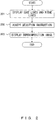
- FIG. 2 is a flowchart illustrating an example of a first superimposed display process performed by the superimposed display apparatus 101 from FIG. 1 .
- the display unit 111 displays edge lines extracted from a shot image of a spatial structure that has been shot by an image shooting apparatus and ridge lines included in a model image represented by model information of that spatial structure, in a manner such that those lines are selectable (step 201).
- the accepting unit 112 accepts a selection instruction indicating an edge line and a ridge line of an overlay target (step 202).
- the display unit 111 displays a superimposition image in which the model image has been superimposed onto the shot image in a manner such that the edge line and the ridge line of the overlay target overlap each other.
- the superimposed display apparatus 101 in FIG. 1 can improve the efficiency of a checking task of comparing a spatial structure and a model represented by model information.
- FIG. 3 illustrates an exemplary functional configuration of a second superimposed display apparatus.
- a superimposed display apparatus 301 in FIG. 3 includes a display unit 311, an accepting unit 312, and a control unit 313.
- FIG. 4 is a flowchart illustrating an example of a second superimposed display process performed by the superimposed display apparatus 301 from FIG. 3 .
- the display unit 311 displays a shot image of a spatial structure that has been shot by an image shooting apparatus, and a model image represented by model information of that spatial structure (step 401).
- the control unit 313 switches between the rule that separate change instructions be accepted for the shot image and the model image, and the rule that a common change instruction be accepted for the shot image and the model image (step 402).
- the superimposed display instruction is an instruction to display a superimposition image in which the model image has been superimposed onto the shot image in a manner such that a reference position on the shot image and a reference position on the model image overlap each other.
- the change instruction is an instruction to enlarge, reduce, move, or rotate the shot image or the model image.
- the superimposed display apparatus 301 in FIG. 3 can improve the efficiency of a checking task of comparing a spatial structure and a model represented by model information.
- FIG. 5 illustrates a specific example of the superimposed display apparatus 101 in FIG. 1 or the superimposed display apparatus 301 in FIG. 3 .
- a superimposed display apparatus 501 in FIG. 5 includes an accepting unit 511, a control unit 512, a display unit 513, and a storage unit 514.
- the accepting unit 511 corresponds to the accepting unit 112 in FIG. 1 and the accepting unit 312 in FIG. 3 ; the control unit 512, the control unit 313 in FIG. 3 ; the display unit 513, the display unit 111 in FIG. 1 and the display unit 311 in FIG. 3 .
- the storage unit 514 stores one or more shot images 521, one or more model files 522, a model image 523, combination information 524, a superimposition image 525, and change information 526.
- the shot image 521 is an image of a spatial structure shot by an image shooting apparatus such as a camera, and may include information indicating an angle of view of the image shooting apparatus.
- the model file 522 is model information representing a three-dimensional CAD model of the spatial structure, and includes vertex information of a plurality of vertexes included in the three-dimensional CAD model and line segment information of a plurality of line segments.
- the model image 523 is an image of a three-dimensional CAD model represented by the model file 522.
- Combination information 524 indicates a combination of an edge line and a ridge line of the overlay target that have been selected by an operator.
- the superimposition image 525 is an image in which the model image 523 has been superimposed onto the shot image 521.
- Change information 526 indicates whether to accept separate change instructions for the shot image 521 and the model image 523, or whether to accept a common change instruction for the shot image 521 and the model image 523, the change instructions being instructions to enlarge, reduce, move, or rotate an image.
- the superimposed display apparatus 501 may be a portable terminal apparatus such as a tablet, a notebook PC, or a smartphone, or may be a fixed terminal apparatus such as a desktop PC.
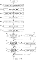
- FIGS. 6A and 6B are flowcharts illustrating a specific example of a superimposed display process performed by the superimposed display apparatus 501 in FIG. 5 .
- An operator inputs an instruction for designating a shot image 521 and a model file 522, and the accepting unit 511 accepts the input instruction (step 601).
- the display unit 513 displays the shot image 521 designated by the instruction accepted by the accepting unit 511 on a screen (step 602).
- FIG. 7 illustrates an example of a displayed shot image 521.
- a rectangular shot image 701 corresponds to a side surface of a cubic spatial structure.
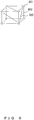
- FIG. 8 illustrates an exemplary three-dimensional CAD model represented by a model file 522 of the spatial structure seen in the shot image 701 in FIG. 7 .
- Vertex information of the model file 522 includes the identification information and three-dimensional coordinates of a vertex 801 and the like of the cube;
- line segment information of the model file 522 includes identification information of line segments 802 and 803 and the like, and identification information indicating the two vertexes at the both ends of each line segment.
- the control unit 512 performs an edge detecting process to extract edge lines from the shot image 521 (step 603), and displays the extracted edge lines on the screen (step 604).
- the control unit 512 may extract straight edge lines only, or may extract straight and curved edge lines.
- FIG. 9 illustrates exemplary edge lines extracted from the shot image 701 in FIG. 7 .
- Edge lines 901-904 are each extracted from a respective one of the four sides of the rectangle of the shot image 701.
- control unit 512 uses vertex information and line segment information of the model file 522 to generate ridge lines of the three-dimensional CAD model (step 605).
- the control unit 512 may extract only a line segment representing a contour feature of a three-dimensional CAD model from a plurality of line segments included in line segment information, and may use the extracted line segment as a ridge line.
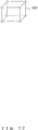
- FIG. 10 illustrates exemplary ridge lines generated from the three-dimensional CAD model in FIG. 8 .
- the line segment 802 in FIG. 8 corresponds to an edge of the cube and represents a contour feature, and accordingly the line segment 802 is extracted as a ridge line 1001.
- the line segment 803 is included on a side surface of the cube and does not represent a contour feature, and accordingly the line segment 803 is not extracted as a ridge line.
- the control unit 512 generates a polygon representing a surface surrounded by the generated ridge lines and stores information on the generated ridge lines and the polygon in the storage unit 514 as a model image 523 (step 606).
- the generated polygon represents a part of the surface of the three-dimensional CAD model.
- FIG. 11 illustrates exemplary polygons generated from the ridge lines in FIG. 10 .
- a polygon 1101 represents a rectangular side face surrounded by four ridge lines corresponding to four edges of the cube.
- the control unit 512 displays the model image 523 on the screen together with the shot image 521 (step 607). As a result, the edge lines extracted from the shot image 521 and the ridge lines and polygon included in the model image 523 are displayed so that the edge lines and the ridge lines can be selected on the screen. Simultaneously, the control unit 512 generates change information 526 indicating that separate change instructions are to be accepted for the shot image 521 and the model image 523, and stores the change information 526 in the storage unit 514.
- FIG. 12 illustrates an exemplary model image 523 displayed using the ridge lines in FIG. 10 and the polygons in FIG. 11 .
- the edge lines 901-904 in FIG. 9 and a model image 1201 of the cube are displayed in this example. Displaying ridge lines and, in addition, the polygons as the model image 1201 can cover and hide the ridge lines on the back-surface side of the three-dimensional CAD model using the polygons, so that the outside shape of the three-dimensional CAD model can be readily grasped.
- the operator checks whether the size of the model image 523 on the screen is suitable (step 608).
- the size of the model image 523 is suitable to indicate a correlation between the edge lines of the shot image 521 and the ridge lines of the model image 523, the operator determines that the size of the model image 523 is suitable.
- the operator inputs a change instruction indicating enlargement or reduction of the model image 523, and the accepting unit 511 accepts the input change instruction (step 611). Then, the control unit 512 adjusts the size of the model image 523 by enlarging or reducing the model image 523 in accordance with the change instruction. For example, the control unit 512 may enlarge or reduce the model image 523 by changing the enlargement or reduction ratio of the ridge lines and the polygons.
- FIG. 13 illustrates an example of size adjustment of the model image 1201 depicted in FIG. 12 .
- the model image 1201 has been enlarged in this example.
- the operator checks whether the orientation of the model image 523 on the screen is suitable (step 609).
- the orientation of the model image 523 is suitable to indicate a correlation between the edge lines of the shot image 521 and the ridge lines of the model image 523, the operator determines that the orientation of the model image 523 is suitable.
- the operator inputs a change instruction indicating rotation of the model image 523, and the accepting unit 511 accepts the input change instruction (step 612). Then, the control unit 512 adjusts the orientation of the model image 523 by rotating the model image 523 in accordance with the change instruction. For example, the control unit 512 may rotate the model image 523 by changing the rotation angle of the ridge lines and the polygons.
- FIG. 14 illustrates an example of orientation adjustment of the model image 1201 depicted in FIG. 13 .
- the model image 1201 rotates counterclockwise in this example.
- the operator checks whether the position of the model image 523 on the screen is suitable (step 610).
- the position of the model image 523 is suitable to indicate a correlation between the edge lines of the shot image 521 and the ridge lines of the model image 523, the operator determines that the position of the model image 523 is suitable.
- the operator inputs a change instruction indicating movement of the model image 523, and the accepting unit 511 accepts the input change instruction (step 613). Then, the control unit 512 adjusts the position of the model image 523 by moving the model image 523 in accordance with the change instruction. For example, the control unit 512 may move the model image 523 by changing the positions of the ridge lines and the polygons.
- FIG. 15 illustrates an example of position adjustment of the model image 1201 depicted in FIG. 14 .
- the model image 1201 has moved upward in this example.
- the operator inputs a selection instruction indicating an edge line and a ridge line to serve as reference positions for superimposed display, and the accepting unit 511 accepts the input selection instruction (step 614). Then, the control unit 512 highlights the edge line and the ridge line indicated by the selection instruction by changing, for example, the color, width, or type of the edge line and the ridge line. Highlighting the edge line and the ridge line allows the operator to readily check the selection result.
- the control unit 512 may display a line segment linking the edge line and the ridge line. Displaying a line segment linking the edge line and the ridge line further improves the efficiency of a task of checking the selection result that is performed by the operator.
- FIG. 16 illustrates an exemplary edge line and ridge line selected on the screen depicted in FIG. 15 .
- an edge line 901 and a ridge line 1601 have been selected, and a line segment 1611 linking the edge line 901 and the ridge line 1601 is displayed.
- the operator checks whether a combination of a highlighted edge line and ridge line is suitable (step 615). When, for example, the highlighted edge line and ridge line correspond to the same ridge line of the spatial structure, the operator determines that the combination is suitable.
- the operator gives an instruction to cancel the combination of the selected lines, and the accepting unit 511 accepts the input instruction (step 622). Then, the control unit 512 cancels the highlighting of the edge line and the ridge line. Simultaneously, the control unit 512 hides the line segment linking the edge line and the ridge line.
- FIG. 17 illustrates examples of an edge line and ridge line after cancellation.
- a combination of a selected edge line 903 and ridge line 1701 has been cancelled, and a line segment 1702 linking the edge line 903 and the ridge line 1701 has been hidden.
- N is an integer that is 1 or greater. As N becomes a lower value, a task time of an operator is shortened, but the accuracy of the superimposed display decreases. Meanwhile, as N becomes a higher value, a task time of an operator is lengthened, but the accuracy of the superimposed display increases. N may be any of 1 to 4.
- step 616 When N combinations have not been selected (NO in step 616), the operator repeats the operations of step 614 and the following steps; when N combinations have been selected (YES in step 616), the operator inputs a superimposition instruction (step 617).
- the accepting unit 511 accepts the input superimposition instruction.
- the control unit 512 generates and stores combination information 524 indicating the selected N combinations in the storage unit 514.
- FIG. 18 illustrates four exemplary combinations of an edge line and a ridge line.
- a combination of an edge line 901 and a ridge line 1601, a combination of an edge line 902 and a ridge line 1602, a combination of an edge line 903 and a ridge line 1603, and a combination of an edge line 904 and a ridge line 1604 have been selected.
- a line segment 1611 linking the edge line 901 and the ridge line 1601, a line segment 1612 linking the edge line 902 and the ridge line 1602, a line segment 1613 linking the edge line 903 and the ridge line 1603, and a line segment 1614 linking the edge line 904 and the ridge line 1604 have been displayed.
- FIG. 19 illustrates an example of combination information 524.
- Each entry of combination information 524 of FIG. 19 includes an edge line ID, a ridge line ID, and a priority.
- An edge ID is identification information of an edge line included in a combination
- a ridge line ID is identification information of a ridge line included in the combination
- a priority indicates the degree of priority of the combination that is determined according to a prescribed standard.
- an order in which a combination of an edge line and a ridge line is selected by the operator may be directly used as a priority, or a higher priority may be given to combinations with more reliable ridge lines.
- a higher priority may be given to combinations with more reliable ridge lines.
- the reliability levels of ridge lines with a high processing accuracy or assembling accuracy may become high, and the reliability levels of ridge lines with a low processing accuracy or assembling accuracy may become low.
- information indicating the reliability of each line segment is added to line segment information of the model file 522, and the control unit 512 determines priorities for combinations by referring to the reliabilities of selected ridge lines.
- E1 to E4 represent the edge line IDs of the edge lines 901 to 904 in FIG. 18 ; L1 to L4, the ridge line IDs of the ridge lines 1601 to 1604.
- a combination of E1 and L1 has the highest priority, and a combination of E4 and L4 has the lowest priority.
- the control unit 512 generates a superimposition image 525 in which a model image 523 has been superimposed onto a shot image 521 in a manner such that an edge line and a ridge line included in each combination in combination information 524 overlap each other, and stores the superimposition image 525 in the storage unit 514 (step 618).
- the control unit 512 may superimpose the model image 523 onto the shot image 521 by adjusting the enlargement or reduction ratio, rotation angle, and position of ridge lines and polygons of the model image 523.
- control unit 512 calculates optimum values for the enlargement or reduction ratio, rotation angle, and position of the ridge lines and polygons, thereby generating a superimposition image 525 with the edge lines and the ridged lines moderately coinciding with each other.
- the control unit 512 cancels highlighting of the edge lines and the ridge lines and hides the edge lines (step 619). Simultaneously, the control unit 512 also hides line segments linking the edge lines and the ridge lines.
- the control unit 512 displays the superimposition image 525 on the screen (step 620).
- the control unit 512 may change, for example, the color, width, and type of an edge line and a ridge line included in each combination in combination information 524, thereby highlighting the edge line and the ridge line. Highlighting the edge line and the ridge line allows the operator to readily check the edge line and the ridge line that have been overlaid in superimposed display.
- the control unit 512 switches the change information 526 in the storage unit 514 to information indicating that a common change instruction is to be accepted for the shot image 521 and the model image 523.
- FIG. 20 illustrates an exemplary superimposition image 525 in which the model image 1201 in FIG. 12 has been superimposed onto the shot image 701 in FIG. 7 .
- the operator looks at the superimposition image 525 on the screen so as to check misalignments between the shot image 521 and the model image 523.
- the operator inputs a change instruction for the superimposition image 525, and, in accordance with change information 526, the accepting unit 511 accepts the input change instruction as a common instruction for the shot image 521 and the model image 523 (step 621).
- the control unit 512 adjusts the size, orientation, or position of the superimposition image 525 by enlarging, reducing, rotating, or moving the entirety of the superimposition image 525 in accordance with the change instruction.
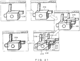
- FIG. 21 illustrates an exemplary superimposed display process on another shot image 521.
- an edge line 2102 is extracted from a shot image 2101 of a spatial structure in an edge detecting process, and a model image 2103 generated from a three-dimensional CAD model of the spatial structure is displayed together with the shot image 2101 and the edge line 2102.
- a combination of an edge line 2111 of the shot image 2101 and a ridge line 2121 of the model image 2103 is highlighted in accordance with a selection instruction input by an operator.
- a combination of an edge line 2112 and a ridge line 2122, a combination of an edge line 2113 and a ridge line 2123, and a combination of an edge line 2114 and a ridge line 2124 are highlighted.
- a line segment 2131 linking the edge line 2111 and the ridge line 2121, a line segment 2132 linking the edge line 2112 and the ridge line 2122, a line segment 2133 linking the edge line 2113 and the ridge line 2123, and a line segment 2134 linking the edge line 2114 and the ridge line 2124 are displayed.
- a superimposition image 2104 is displayed in which the model image 2103 has been superimposed onto the shot image 2101 in a manner such that the edge lines 2111-2114 respectively overlap the ridge lines 2121-2124.
- FIG. 22 is a flowchart illustrating an exemplary adjusting process performed after the superimposed display process in FIG. 6B is performed.
- the size, orientation, or position of a shot image 521 or model image 523 included in a superimposition image 525 is adjusted according to priorities included in combination information 524.
- An operator looks at the superimposition image 525 on the screen so as to check whether the shot image 521 and the model image 523 are misaligned (step 2201). When the shot image 521 and the model image 523 are aligned (NO in step 2201), the operator ends the checking task.
- control unit 512 sets 1 as control variable i, which indicates priority (step 2202).
- the control unit 512 selects an entry with priority i in combination information 524, obtains an edge line ID and a ridge line ID from the selected entry, and highlights an edge line and ridge line indicated by the obtained edge line ID and ridge line ID (step 2203). The operator determines whether to make an adjustment using a combination of the highlighted edge line and ridge line as a reference.
- the operator In making an adjustment using the combination of the highlighted edge line and ridge line as a reference (YES in step 2203), the operator inputs an execution instruction, and the accepting unit 511 accepts the input execution instruction.
- the control unit 512 adjusts the superimposition image 525 by enlarging, reducing, rotating, or moving the model image 523 in a manner such that the highlighted edge line and ridge line coincide with each other (step 2204).
- the control unit 512 checks whether i has reached N (step 2205). When i has not reached N (NO in step 2205), the control unit 512 increments i by one (step 2206), and repeats the processes of step 2203 and the following steps. When i has reached N (YES in step 2205), the control unit 512 ends the process.
- FIG. 23 illustrates an exemplary adjusting process on the superimposition image 2104 in FIG. 21 .
- the priorities of combinations of an edge line and a ridge line are as follows.
- a superimposition image 2104 After a superimposition image 2104 has been displayed in which a model image 2103 has been superimposed onto a shot image 2101, when an operator designates a combination with priority 1 or 2 as a reference, the superimposition image 2104 is replaced with a superimposition image 2301 on the screen.
- the superimposition image 2301 In which the edge line 2111 and the ridge line 2121 coincide with each other, is displayed; when a combination with priority 2 is designated, the superimposition image 2301, in which the edge line 2112 and the ridge line 2122 coincide with each other, is displayed.
- the superimposition image 2301 is replaced with a superimposition image 2302 on the screen.
- the superimposition image 2302 in which the edge line 2113 and the ridge line 2123 coincide with each other, is displayed.
- the superimposition image 2302 is replaced with a superimposition image 2303 on the screen.
- the superimposition image 2303 in which the edge line 2114 and the ridge line 2124 coincide with each other, is displayed.
- the configurations of the superimposed display apparatus 101 in FIG. 1 , the superimposed display apparatus 301 in FIG. 3 , and the superimposed display apparatus 501 in FIG. 5 are merely examples, and some components may be omitted or changed according to the intended use or conditions of the superimposed display apparatuses.
- change information 526 in FIG. 5 may be omitted; when the operator does not input a selection instruction indicating an edge line and a ridge line of an overlay target, combination information 524 may be omitted.
- FIGS. 2 , 4 , 6A , 6B , and 22 are merely examples, and some processes may be omitted or changed according to the configuration or conditions of the superimposed display apparatus. For example, when polygons of the model image 523 do not need to be displayed in the superimposed display processes in FIGS. 6A and 6B , the process of step 606 may be omitted. When the size, orientation, and position of the model image 523 do not need to be adjusted, the processes of steps 608-613 may be omitted.
- steps 615 and 622 may be omitted.
- the process of step 621 may be omitted.
- the processes of steps 608-617 may be omitted.
- a set of steps 602-604 and a set of steps 605-607 may be performed in reverse order.
- the control unit 512 does not always need to highlight a selected edge line and ridge line.
- the shot images, model information, edge lines, ridge lines, polygons, model images, superimposition images, and combination information in FIGS. 7-21 and 23 are merely examples, and other images or other pieces of information may be used.
- the superimposed display apparatus 101 in FIG. 1 , the superimposed display apparatus 301 in FIG. 3 , and the superimposed display apparatus 501 in FIG. 5 can be implemented using, for example, an information processing apparatus (computer) such as that depicted in FIG. 24 .
- the information processing apparatus in FIG. 24 includes a Central Processing Unit (CPU) 2401, a memory 2402, an input device 2403, an output device 2404, an auxiliary storage device 2405, a medium driving device 2406, and a network connecting device 2407. These elements are connected to each other by a bus 2408.
- CPU Central Processing Unit
- the memory 2402 is, for example, a semiconductor memory such as a Read Only Memory (ROM), a Random Access Memory (RAM), or a flash memory, and stores programs and data for use in processing.
- the memory 2402 may be used as the storage unit 514 in FIG. 5 .
- the CPU 2401 (processor) operates as the control unit 313 in FIG. 3 and the control unit 512 in FIG. 5 by, for example, executing a program using the memory 2402.
- the input device 2403 is, for example, a keyboard or a pointing device and is used to input an instruction or information from an operator.
- the input device 2403 may be used as the accepting unit 112 in FIG. 1 , the accepting unit 312 in FIG. 3 , and the accepting unit 511 in FIG. 5 .
- the output device 2404 is, for example, a display device, a printer, or a speaker, and is used to output a query or a processing result to the operator.
- the processing result may be a superimposition image 525.
- the output device 2404 may be used as the display unit 111 in FIG. 1 , the display unit 311 in FIG. 3 , and the display unit 513 in FIG. 5 .
- the auxiliary storage device 2405 is, for example, a magnetic disk device, an optical disk device, a magneto-optical disk device, or a tape device.
- the auxiliary storage device 2405 may be a hard disk drive or a flash memory.
- the information processing apparatus may store a program and data in the auxiliary storage device 2405 and load them into the memory 2402 for use.
- the auxiliary storage device 2405 may be used as the storage unit 514 in FIG. 5 .
- the medium driving device 2406 drives a portable recording medium 2409 and accesses items recorded therein.
- the portable recording medium 2409 is, for example, a memory device, a flexible disk, an optical disk, or a magneto-optical disk.
- the portable recording medium 2409 may be, for example, a Compact Disk Read Only Memory (CD-ROM), a Digital Versatile Disk (DVD), or a Universal Serial Bus (USB) memory.
- CD-ROM Compact Disk Read Only Memory
- DVD Digital Versatile Disk
- USB Universal Serial Bus
- a computer-readable recording medium that stores a program and data to be used for processing is a physical (non-transitory) recording medium such as the memory 2402, the auxiliary storage apparatus 2405, or the portable recording medium 2409.
- the network connecting device 2407 is a communication interface that is connected to a communication network such as a Local Area Network or a Wide Area Network and that performs data conversion associated with a communication.
- the information processing apparatus may receive a program and data from an external apparatus via the network connecting device 2407 and load them into the memory 2402 for use.
- the information processing apparatus does not need to include all of the elements in FIG. 24 , and one or more of the elements may be omitted according to the intended use or conditions.
- the network connecting device 2407 may be omitted when a communication does not need to be performed with another apparatus; the medium driving device 2406 may be omitted when the portable recording medium 2409 is not used.
- the information processing apparatus may include a call apparatus such as a microphone or a speaker, or may include an image shooting apparatus such as a camera.
Landscapes
- Engineering & Computer Science (AREA)
- Physics & Mathematics (AREA)
- General Physics & Mathematics (AREA)
- Theoretical Computer Science (AREA)
- Software Systems (AREA)
- Computer Graphics (AREA)
- General Engineering & Computer Science (AREA)
- Computer Hardware Design (AREA)
- Architecture (AREA)
- Quality & Reliability (AREA)
- Computer Vision & Pattern Recognition (AREA)
- Geometry (AREA)
- Remote Sensing (AREA)
- Radar, Positioning & Navigation (AREA)
- Processing Or Creating Images (AREA)
- Image Processing (AREA)
- Controls And Circuits For Display Device (AREA)
- Image Analysis (AREA)
Applications Claiming Priority (2)
| Application Number | Priority Date | Filing Date | Title |
|---|---|---|---|
| JP2015218318A JP6661980B2 (ja) | 2015-11-06 | 2015-11-06 | 重畳表示方法、重畳表示装置、及び重畳表示プログラム |
| EP16194556.3A EP3166083B1 (fr) | 2015-11-06 | 2016-10-19 | Procédé d'affichages superposés et appareil d'affichages superposés |
Related Parent Applications (2)
| Application Number | Title | Priority Date | Filing Date |
|---|---|---|---|
| EP16194556.3A Division-Into EP3166083B1 (fr) | 2015-11-06 | 2016-10-19 | Procédé d'affichages superposés et appareil d'affichages superposés |
| EP16194556.3A Division EP3166083B1 (fr) | 2015-11-06 | 2016-10-19 | Procédé d'affichages superposés et appareil d'affichages superposés |
Publications (1)
| Publication Number | Publication Date |
|---|---|
| EP3340189A1 true EP3340189A1 (fr) | 2018-06-27 |
Family
ID=57280960
Family Applications (2)
| Application Number | Title | Priority Date | Filing Date |
|---|---|---|---|
| EP16194556.3A Not-in-force EP3166083B1 (fr) | 2015-11-06 | 2016-10-19 | Procédé d'affichages superposés et appareil d'affichages superposés |
| EP18157139.9A Withdrawn EP3340189A1 (fr) | 2015-11-06 | 2016-10-19 | Procédé d'affichages superposés et appareil d'affichages superposés |
Family Applications Before (1)
| Application Number | Title | Priority Date | Filing Date |
|---|---|---|---|
| EP16194556.3A Not-in-force EP3166083B1 (fr) | 2015-11-06 | 2016-10-19 | Procédé d'affichages superposés et appareil d'affichages superposés |
Country Status (5)
| Country | Link |
|---|---|
| US (1) | US10304159B2 (fr) |
| EP (2) | EP3166083B1 (fr) |
| JP (1) | JP6661980B2 (fr) |
| CN (1) | CN107016726B (fr) |
| MY (1) | MY190811A (fr) |
Families Citing this family (29)
| Publication number | Priority date | Publication date | Assignee | Title |
|---|---|---|---|---|
| JP6996147B2 (ja) | 2017-07-27 | 2022-01-17 | 株式会社大林組 | 検査処理システム、検査処理方法及び検査処理プログラム |
| JP6939195B2 (ja) * | 2017-07-27 | 2021-09-22 | 株式会社大林組 | 検査処理システム、検査処理方法及び検査処理プログラム |
| JP6996200B2 (ja) | 2017-09-29 | 2022-01-17 | 富士通株式会社 | 画像処理方法、画像処理装置、および画像処理プログラム |
| US10699165B2 (en) | 2017-10-30 | 2020-06-30 | Palo Alto Research Center Incorporated | System and method using augmented reality for efficient collection of training data for machine learning |
| JP7003617B2 (ja) * | 2017-12-12 | 2022-01-20 | 富士通株式会社 | 推定装置、推定方法、及び推定プログラム |
| JP6962242B2 (ja) * | 2018-03-07 | 2021-11-05 | 富士通株式会社 | 情報処理装置,重畳表示プログラム,重畳表示方法 |
| JP7059701B2 (ja) * | 2018-03-08 | 2022-04-26 | 富士通株式会社 | 推定装置、推定方法、及び推定プログラム |
| JP7027978B2 (ja) | 2018-03-14 | 2022-03-02 | 富士通株式会社 | 検査装置、検査方法、及び検査プログラム |
| JP7172179B2 (ja) * | 2018-06-27 | 2022-11-16 | 富士通株式会社 | 表示制御方法、情報処理装置及び表示制御プログラム |
| JP7063165B2 (ja) | 2018-07-26 | 2022-05-09 | 富士通株式会社 | 計測装置、計測方法及び計測プログラム |
| JP7180283B2 (ja) * | 2018-10-30 | 2022-11-30 | 富士通株式会社 | 画像処理装置及び画像処理方法 |
| US11138759B2 (en) | 2018-12-13 | 2021-10-05 | Fujitsu Limited | Image processing apparatus and image processing method |
| US11443495B2 (en) * | 2018-12-31 | 2022-09-13 | Palo Alto Research Center Incorporated | Alignment- and orientation-based task assistance in an AR environment |
| CN109800736B (zh) * | 2019-02-01 | 2023-07-21 | 东北大学 | 一种基于遥感影像和深度学习的道路提取方法 |
| US11657506B2 (en) * | 2019-03-06 | 2023-05-23 | General Electric Company | Systems and methods for autonomous robot navigation |
| JP7265143B2 (ja) * | 2019-05-30 | 2023-04-26 | 富士通株式会社 | 表示制御方法、表示制御プログラムおよび情報処理装置 |
| JP7379052B2 (ja) * | 2019-09-30 | 2023-11-14 | キヤノン株式会社 | 表示制御装置、方法及びプログラム |
| JP7470511B2 (ja) * | 2019-12-17 | 2024-04-18 | 荏原環境プラント株式会社 | 情報処理システム、情報処理方法、情報処理プログラム |
| US11288792B2 (en) * | 2020-02-19 | 2022-03-29 | Palo Alto Research Center Incorporated | Method and system for change detection using AR overlays |
| CN111766423A (zh) * | 2020-09-02 | 2020-10-13 | 深圳市鼎阳科技股份有限公司 | 一种示波器的信号显示方法及示波器 |
| JP7513496B2 (ja) * | 2020-10-30 | 2024-07-09 | 株式会社エビデント | 画像表示方法、表示制御装置、およびプログラム |
| US12236344B2 (en) | 2021-03-19 | 2025-02-25 | Xerox Corporation | System and method for performing collaborative learning of machine representations for a target concept |
| WO2022224447A1 (fr) * | 2021-04-23 | 2022-10-27 | 日本電気株式会社 | Dispositif de commande, procédé de commande et support de stockage |
| US11917289B2 (en) | 2022-06-14 | 2024-02-27 | Xerox Corporation | System and method for interactive feedback in data collection for machine learning in computer vision tasks using augmented reality |
| US12223595B2 (en) | 2022-08-02 | 2025-02-11 | Xerox Corporation | Method and system for mixing static scene and live annotations for efficient labeled image dataset collection |
| US12367656B2 (en) | 2022-09-08 | 2025-07-22 | Xerox Corporation | Method and system for semi-supervised state transition detection for object tracking |
| JP2024100554A (ja) * | 2023-01-16 | 2024-07-26 | 富士通株式会社 | 設定プログラム、設定方法および情報処理装置 |
| US12475649B2 (en) | 2023-01-19 | 2025-11-18 | Xerox Corporation | Method and system for facilitating generation of background replacement masks for improved labeled image dataset collection |
| JP7799330B2 (ja) * | 2023-09-22 | 2026-01-15 | 高丸工業株式会社 | ロボット操作システムの動作方法 |
Citations (5)
| Publication number | Priority date | Publication date | Assignee | Title |
|---|---|---|---|---|
| JPH11239989A (ja) | 1998-02-25 | 1999-09-07 | Fujitsu Ltd | ロボットシミュレーションにおけるキャリブレーション装置 |
| EP1993072A1 (fr) * | 2007-05-18 | 2008-11-19 | Siemens Aktiengesellschaft | Procédé pour la comparaison d'un modèle informatique 3D et d'une installation industrielle telle que bâtie |
| JP2010211746A (ja) | 2009-03-12 | 2010-09-24 | Omron Corp | 3次元認識結果の表示方法および3次元視覚センサ |
| WO2012173141A1 (fr) | 2011-06-16 | 2012-12-20 | オリンパス株式会社 | Appareil de traitement d'image, procédé de traitement d'image et programme |
| DE102012003256A1 (de) * | 2012-02-21 | 2013-08-22 | Testo Ag | Auswerteverfahren für ein ortsauflösendes Messergebnis und Auswerteeinrichtung |
Family Cites Families (24)
| Publication number | Priority date | Publication date | Assignee | Title |
|---|---|---|---|---|
| CA2106146A1 (fr) * | 1992-10-16 | 1994-04-17 | Peter R. Doherty, Jr. | Comparateur video pour la conception assistee par ordinateur |
| JP3596753B2 (ja) * | 2000-05-10 | 2004-12-02 | 株式会社ミツトヨ | 画像測定装置用パートプログラム生成装置及び方法 |
| JP4727068B2 (ja) | 2001-05-29 | 2011-07-20 | 株式会社トプコン | 施工監視システム、施工管理方法 |
| US7076093B2 (en) * | 2002-09-16 | 2006-07-11 | Lee Shih-Jong J | Structure-guided image inspection |
| JP2005339127A (ja) | 2004-05-26 | 2005-12-08 | Olympus Corp | 画像情報表示装置及び画像情報表示方法 |
| JP2006072543A (ja) * | 2004-08-31 | 2006-03-16 | Canon Inc | 面選択方法、属性情報設定方法および情報処理装置 |
| JP4434890B2 (ja) * | 2004-09-06 | 2010-03-17 | キヤノン株式会社 | 画像合成方法及び装置 |
| JP4764663B2 (ja) * | 2005-05-30 | 2011-09-07 | 富士通株式会社 | 仮想3次元座標空間における幾何形状の自動認識方法、その3次元cadシステム及び3次元cadプログラム |
| EP1804154A3 (fr) * | 2005-12-27 | 2012-08-08 | Poston Timothy | Dispositif de saisie informatique permettant trois degrés de liberté et procédés de saisie et de retour associés |
| DE102006005044B4 (de) * | 2006-02-03 | 2011-01-27 | Metaio Gmbh | Verfahren und System zur Bestimmung eines Datenmodells zur Überlagerung mit einem realen Objekt in einem Verfahren zur Objektverfolgung |
| JP2007280354A (ja) * | 2006-03-16 | 2007-10-25 | Ricoh Co Ltd | 三次元形状処理装置、三次元形状処理方法、三次元形状処理プログラム、記録媒体、パーツカタログ・システム、パーツカタログ作成方法、及びプログラム |
| JP5408852B2 (ja) * | 2007-08-09 | 2014-02-05 | 株式会社日立ハイテクノロジーズ | パターン測定装置 |
| JP5561975B2 (ja) * | 2009-03-09 | 2014-07-30 | カルソニックカンセイ株式会社 | 表面加工データの作成方法および装置 |
| JP5293501B2 (ja) * | 2009-08-26 | 2013-09-18 | 富士通株式会社 | 3次元データ表示装置およびプログラム |
| CN101794189A (zh) * | 2009-09-22 | 2010-08-04 | 俞长根 | 图像显示方法 |
| JP2011180066A (ja) | 2010-03-03 | 2011-09-15 | Horon:Kk | 画像比較方法および画像比較プログラム |
| DE112010005978B4 (de) * | 2010-11-04 | 2015-10-01 | Mitsubishi Electric Corporation | Verfahren und Vorrichtung zum Erschaffen eines numerisch gesteuerten Bearbeitungsprogramms und Programm zum Veranlassen eines Computers zum Realisieren desselben Verfahrens |
| JP2012203458A (ja) | 2011-03-23 | 2012-10-22 | Fuji Xerox Co Ltd | 画像処理装置及びプログラム |
| US8780223B2 (en) * | 2011-03-31 | 2014-07-15 | VISIONx INC. | Automatic determination of compliance of a part with a reference drawing |
| US20130050207A1 (en) | 2011-08-24 | 2013-02-28 | General Electric Company | Method and system for navigating, segmenting, and extracting a three-dimensional image |
| JP2013167481A (ja) | 2012-02-14 | 2013-08-29 | Olympus Corp | 画像処理装置およびプログラム |
| US9816904B2 (en) * | 2012-12-17 | 2017-11-14 | Nippon Steel & Sumitomo Metal Corporation | Analyzing method of spot welded portion, analyzing program of spot welded portion, recording medium and analyzing apparatus of spot welded portion |
| US9530250B2 (en) * | 2013-12-10 | 2016-12-27 | Dassault Systemes | Augmented reality updating of 3D CAD models |
| WO2015107789A1 (fr) * | 2014-01-16 | 2015-07-23 | コニカミノルタ株式会社 | Appareil de formation d'image bidimensionnelle, appareil de formation d'image tridimensionnelle, procédé de formation d'image bidimensionnelle et procédé de formation d'image tridimensionnelle |
-
2015
- 2015-11-06 JP JP2015218318A patent/JP6661980B2/ja active Active
-
2016
- 2016-10-12 US US15/291,161 patent/US10304159B2/en active Active
- 2016-10-19 EP EP16194556.3A patent/EP3166083B1/fr not_active Not-in-force
- 2016-10-19 EP EP18157139.9A patent/EP3340189A1/fr not_active Withdrawn
- 2016-10-26 MY MYPI2016703920A patent/MY190811A/en unknown
- 2016-10-28 CN CN201610971866.6A patent/CN107016726B/zh not_active Expired - Fee Related
Patent Citations (5)
| Publication number | Priority date | Publication date | Assignee | Title |
|---|---|---|---|---|
| JPH11239989A (ja) | 1998-02-25 | 1999-09-07 | Fujitsu Ltd | ロボットシミュレーションにおけるキャリブレーション装置 |
| EP1993072A1 (fr) * | 2007-05-18 | 2008-11-19 | Siemens Aktiengesellschaft | Procédé pour la comparaison d'un modèle informatique 3D et d'une installation industrielle telle que bâtie |
| JP2010211746A (ja) | 2009-03-12 | 2010-09-24 | Omron Corp | 3次元認識結果の表示方法および3次元視覚センサ |
| WO2012173141A1 (fr) | 2011-06-16 | 2012-12-20 | オリンパス株式会社 | Appareil de traitement d'image, procédé de traitement d'image et programme |
| DE102012003256A1 (de) * | 2012-02-21 | 2013-08-22 | Testo Ag | Auswerteverfahren für ein ortsauflösendes Messergebnis und Auswerteeinrichtung |
Non-Patent Citations (4)
| Title |
|---|
| DURAISAMY PRAKASH ET AL: "Coarse automated registration of visual imagery with three-dimensional light detection and ranging models", JOURNAL OF ELECTRONIC IMAGING, S P I E - INTERNATIONAL SOCIETY FOR OPTICAL ENGINEERING, US, vol. 22, no. 3, 1 July 2013 (2013-07-01), pages 33035, XP060026283, ISSN: 1017-9909, [retrieved on 20130926], DOI: 10.1117/1.JEI.22.3.033035 * |
| IMPEROLI M ET AL: "D<2>CO: Fast and Robust Registration of 3D Textureless Objects Using the Directional Chamfer Distance", COMPUTER VISION SYSTEMS - 10TH INTERNATIONAL CONFERENCE, ICVS 2015. PROCEEDINGS: LNCS 9163 SPRINGER INTERNATIONAL PUBLISHING CHAM, SWITZERLAND, 9 July 2015 (2015-07-09) - 9 July 2015 (2015-07-09), pages 316 - 328, XP002781025, ISBN: 978-3-319-20903-6 * |
| SCHOENFELDER R ET AL: "Augmented Reality for Industrial Building Acceptance", VIRTUAL REALITY CONFERENCE, 2008. VR '08. IEEE, IEEE, PISCATAWAY, NJ, USA, 8 March 2008 (2008-03-08), pages 83 - 90, XP031340003, ISBN: 978-1-4244-1971-5 * |
| ZHANG XI ET AL: "Alignment of 3D Building Models with Satellite Images Using Extended Chamfer Matching", 2014 IEEE CONFERENCE ON COMPUTER VISION AND PATTERN RECOGNITION WORKSHOPS, IEEE, 23 June 2014 (2014-06-23), pages 746 - 753, XP032649673, DOI: 10.1109/CVPRW.2014.115 * |
Also Published As
| Publication number | Publication date |
|---|---|
| JP2017091078A (ja) | 2017-05-25 |
| US10304159B2 (en) | 2019-05-28 |
| JP6661980B2 (ja) | 2020-03-11 |
| EP3166083B1 (fr) | 2021-02-24 |
| US20170132752A1 (en) | 2017-05-11 |
| CN107016726B (zh) | 2020-11-03 |
| MY190811A (en) | 2022-05-12 |
| EP3166083A3 (fr) | 2017-09-20 |
| EP3166083A2 (fr) | 2017-05-10 |
| CN107016726A (zh) | 2017-08-04 |
Similar Documents
| Publication | Publication Date | Title |
|---|---|---|
| EP3166083B1 (fr) | Procédé d'affichages superposés et appareil d'affichages superposés | |
| US9858728B2 (en) | Interactive tool for inspecting and repairing three dimensional models | |
| EP3813025A1 (fr) | Génération de contenu de réalité augmentée pour objets inconnus | |
| KR101473956B1 (ko) | 2d 평면도를 기초로 한 3d 공간정보 모델링 방법 및 해당 3d 공간 모델을 이용한 영상 관제 시스템 | |
| EP2696573A2 (fr) | Procédé de génération d'une image panoramique, dispositif de terminal utilisateur et support d'enregistrement lisible par ordinateur | |
| JP5986261B1 (ja) | 画面制御のための効率的なインタフェースを提供するシステムおよび方法 | |
| JP2018147065A (ja) | 点群データ処理装置、点群データ処理方法、点群データ処理用プログラム | |
| AU2020221180B2 (en) | Augmented reality model orientation alignment | |
| KR20150026396A (ko) | 이미지를 합성하기 위한 방법 및 그 전자 장치 | |
| JP5195641B2 (ja) | ハーネス検証装置およびハーネス検証プログラム | |
| KR102895317B1 (ko) | 지원 시스템, 지원 프로그램 및 제어 방법 | |
| JP6687582B2 (ja) | 情報処理装置 | |
| JP7334460B2 (ja) | 作業支援装置及び作業支援方法 | |
| KR20210023663A (ko) | 2d 이미지를 활용하여 3d 컨텐츠를 생성하는 영상 처리 방법 및 영상 처리 장치 | |
| US20160357880A1 (en) | Computer-readable storage medium, design apparatus, and design method | |
| JP4756899B2 (ja) | 情報処理装置、情報処理方法 | |
| JP4905211B2 (ja) | 3次元モデル表示装置、3次元モデル表示方法、及び、3次元モデル表示プログラム | |
| JP6161290B2 (ja) | 表示制御装置、表示制御方法及びそのプログラム | |
| EP1883028A2 (fr) | Procédé et appareil pour la production d'une vue transversale combinée | |
| JP2011002968A (ja) | プログラム、記録媒体及び表示制御装置 | |
| EP4020400A2 (fr) | Procédé de traitement d'image et dispositif de traitement d'image pour générer un contenu 3d au moyen d'images 2d | |
| JP6188365B2 (ja) | 情報処理装置、情報処理装置の制御方法、コンピュータプログラム | |
| US20240345715A1 (en) | Data analysis device and method | |
| JP4946936B2 (ja) | 3次元モデルの関節設定方法および関節設定プログラム | |
| WO2011129880A1 (fr) | Procédé d'augmentation de réalité au moyen d'un équipement de commande utilisant un dispositif mobile |
Legal Events
| Date | Code | Title | Description |
|---|---|---|---|
| PUAI | Public reference made under article 153(3) epc to a published international application that has entered the european phase |
Free format text: ORIGINAL CODE: 0009012 |
|
| STAA | Information on the status of an ep patent application or granted ep patent |
Free format text: STATUS: THE APPLICATION HAS BEEN PUBLISHED |
|
| AC | Divisional application: reference to earlier application |
Ref document number: 3166083 Country of ref document: EP Kind code of ref document: P |
|
| AK | Designated contracting states |
Kind code of ref document: A1 Designated state(s): AL AT BE BG CH CY CZ DE DK EE ES FI FR GB GR HR HU IE IS IT LI LT LU LV MC MK MT NL NO PL PT RO RS SE SI SK SM TR |
|
| AX | Request for extension of the european patent |
Extension state: BA ME |
|
| STAA | Information on the status of an ep patent application or granted ep patent |
Free format text: STATUS: REQUEST FOR EXAMINATION WAS MADE |
|
| 17P | Request for examination filed |
Effective date: 20181030 |
|
| RBV | Designated contracting states (corrected) |
Designated state(s): AL AT BE BG CH CY CZ DE DK EE ES FI FR GB GR HR HU IE IS IT LI LT LU LV MC MK MT NL NO PL PT RO RS SE SI SK SM TR |
|
| STAA | Information on the status of an ep patent application or granted ep patent |
Free format text: STATUS: EXAMINATION IS IN PROGRESS |
|
| 17Q | First examination report despatched |
Effective date: 20210217 |
|
| GRAP | Despatch of communication of intention to grant a patent |
Free format text: ORIGINAL CODE: EPIDOSNIGR1 |
|
| STAA | Information on the status of an ep patent application or granted ep patent |
Free format text: STATUS: GRANT OF PATENT IS INTENDED |
|
| INTG | Intention to grant announced |
Effective date: 20231120 |
|
| STAA | Information on the status of an ep patent application or granted ep patent |
Free format text: STATUS: THE APPLICATION IS DEEMED TO BE WITHDRAWN |
|
| 18D | Application deemed to be withdrawn |
Effective date: 20240321 |