EP3340355B1 - Hybrides leistungssystem und steuerverfahren dafür - Google Patents
Hybrides leistungssystem und steuerverfahren dafür Download PDFInfo
- Publication number
- EP3340355B1 EP3340355B1 EP16382626.6A EP16382626A EP3340355B1 EP 3340355 B1 EP3340355 B1 EP 3340355B1 EP 16382626 A EP16382626 A EP 16382626A EP 3340355 B1 EP3340355 B1 EP 3340355B1
- Authority
- EP
- European Patent Office
- Prior art keywords
- fuel cell
- cell stack
- battery
- voltage
- conductive
- Prior art date
- Legal status (The legal status is an assumption and is not a legal conclusion. Google has not performed a legal analysis and makes no representation as to the accuracy of the status listed.)
- Active
Links
Images





Classifications
-
- H—ELECTRICITY
- H01—ELECTRIC ELEMENTS
- H01M—PROCESSES OR MEANS, e.g. BATTERIES, FOR THE DIRECT CONVERSION OF CHEMICAL ENERGY INTO ELECTRICAL ENERGY
- H01M8/00—Fuel cells; Manufacture thereof
- H01M8/24—Grouping of fuel cells, e.g. stacking of fuel cells
- H01M8/2465—Details of groupings of fuel cells
-
- H—ELECTRICITY
- H01—ELECTRIC ELEMENTS
- H01M—PROCESSES OR MEANS, e.g. BATTERIES, FOR THE DIRECT CONVERSION OF CHEMICAL ENERGY INTO ELECTRICAL ENERGY
- H01M16/00—Structural combinations of different types of electrochemical generators
- H01M16/003—Structural combinations of different types of electrochemical generators of fuel cells with other electrochemical devices, e.g. capacitors, electrolysers
- H01M16/006—Structural combinations of different types of electrochemical generators of fuel cells with other electrochemical devices, e.g. capacitors, electrolysers of fuel cells with rechargeable batteries
-
- H—ELECTRICITY
- H01—ELECTRIC ELEMENTS
- H01M—PROCESSES OR MEANS, e.g. BATTERIES, FOR THE DIRECT CONVERSION OF CHEMICAL ENERGY INTO ELECTRICAL ENERGY
- H01M8/00—Fuel cells; Manufacture thereof
- H01M8/02—Details
- H01M8/0202—Collectors; Separators, e.g. bipolar separators; Interconnectors
-
- H—ELECTRICITY
- H01—ELECTRIC ELEMENTS
- H01M—PROCESSES OR MEANS, e.g. BATTERIES, FOR THE DIRECT CONVERSION OF CHEMICAL ENERGY INTO ELECTRICAL ENERGY
- H01M8/00—Fuel cells; Manufacture thereof
- H01M8/02—Details
- H01M8/0202—Collectors; Separators, e.g. bipolar separators; Interconnectors
- H01M8/0258—Collectors; Separators, e.g. bipolar separators; Interconnectors characterised by the configuration of channels, e.g. by the flow field of the reactant or coolant
-
- H—ELECTRICITY
- H01—ELECTRIC ELEMENTS
- H01M—PROCESSES OR MEANS, e.g. BATTERIES, FOR THE DIRECT CONVERSION OF CHEMICAL ENERGY INTO ELECTRICAL ENERGY
- H01M8/00—Fuel cells; Manufacture thereof
- H01M8/04—Auxiliary arrangements, e.g. for control of pressure or for circulation of fluids
- H01M8/04298—Processes for controlling fuel cells or fuel cell systems
- H01M8/04313—Processes for controlling fuel cells or fuel cell systems characterised by the detection or assessment of variables; characterised by the detection or assessment of failure or abnormal function
- H01M8/04537—Electric variables
- H01M8/04544—Voltage
- H01M8/04559—Voltage of fuel cell stacks
-
- H—ELECTRICITY
- H01—ELECTRIC ELEMENTS
- H01M—PROCESSES OR MEANS, e.g. BATTERIES, FOR THE DIRECT CONVERSION OF CHEMICAL ENERGY INTO ELECTRICAL ENERGY
- H01M8/00—Fuel cells; Manufacture thereof
- H01M8/04—Auxiliary arrangements, e.g. for control of pressure or for circulation of fluids
- H01M8/04298—Processes for controlling fuel cells or fuel cell systems
- H01M8/04313—Processes for controlling fuel cells or fuel cell systems characterised by the detection or assessment of variables; characterised by the detection or assessment of failure or abnormal function
- H01M8/04537—Electric variables
- H01M8/04544—Voltage
- H01M8/04567—Voltage of auxiliary devices, e.g. batteries, capacitors
-
- H—ELECTRICITY
- H01—ELECTRIC ELEMENTS
- H01M—PROCESSES OR MEANS, e.g. BATTERIES, FOR THE DIRECT CONVERSION OF CHEMICAL ENERGY INTO ELECTRICAL ENERGY
- H01M8/00—Fuel cells; Manufacture thereof
- H01M8/04—Auxiliary arrangements, e.g. for control of pressure or for circulation of fluids
- H01M8/04298—Processes for controlling fuel cells or fuel cell systems
- H01M8/04694—Processes for controlling fuel cells or fuel cell systems characterised by variables to be controlled
- H01M8/04858—Electric variables
- H01M8/04865—Voltage
- H01M8/0488—Voltage of fuel cell stacks
-
- H—ELECTRICITY
- H01—ELECTRIC ELEMENTS
- H01M—PROCESSES OR MEANS, e.g. BATTERIES, FOR THE DIRECT CONVERSION OF CHEMICAL ENERGY INTO ELECTRICAL ENERGY
- H01M8/00—Fuel cells; Manufacture thereof
- H01M8/04—Auxiliary arrangements, e.g. for control of pressure or for circulation of fluids
- H01M8/04298—Processes for controlling fuel cells or fuel cell systems
- H01M8/04694—Processes for controlling fuel cells or fuel cell systems characterised by variables to be controlled
- H01M8/04858—Electric variables
- H01M8/04925—Power, energy, capacity or load
- H01M8/0494—Power, energy, capacity or load of fuel cell stacks
-
- H—ELECTRICITY
- H01—ELECTRIC ELEMENTS
- H01M—PROCESSES OR MEANS, e.g. BATTERIES, FOR THE DIRECT CONVERSION OF CHEMICAL ENERGY INTO ELECTRICAL ENERGY
- H01M8/00—Fuel cells; Manufacture thereof
- H01M8/04—Auxiliary arrangements, e.g. for control of pressure or for circulation of fluids
- H01M8/04298—Processes for controlling fuel cells or fuel cell systems
- H01M8/04694—Processes for controlling fuel cells or fuel cell systems characterised by variables to be controlled
- H01M8/04858—Electric variables
- H01M8/04925—Power, energy, capacity or load
- H01M8/04947—Power, energy, capacity or load of auxiliary devices, e.g. batteries, capacitors
-
- H—ELECTRICITY
- H01—ELECTRIC ELEMENTS
- H01M—PROCESSES OR MEANS, e.g. BATTERIES, FOR THE DIRECT CONVERSION OF CHEMICAL ENERGY INTO ELECTRICAL ENERGY
- H01M8/00—Fuel cells; Manufacture thereof
- H01M8/24—Grouping of fuel cells, e.g. stacking of fuel cells
- H01M8/2465—Details of groupings of fuel cells
- H01M8/247—Arrangements for tightening a stack, for accommodation of a stack in a tank or for assembling different tanks
- H01M8/248—Means for compression of the fuel cell stacks
-
- H—ELECTRICITY
- H01—ELECTRIC ELEMENTS
- H01M—PROCESSES OR MEANS, e.g. BATTERIES, FOR THE DIRECT CONVERSION OF CHEMICAL ENERGY INTO ELECTRICAL ENERGY
- H01M8/00—Fuel cells; Manufacture thereof
- H01M8/24—Grouping of fuel cells, e.g. stacking of fuel cells
- H01M8/249—Grouping of fuel cells, e.g. stacking of fuel cells comprising two or more groupings of fuel cells, e.g. modular assemblies
-
- H—ELECTRICITY
- H02—GENERATION; CONVERSION OR DISTRIBUTION OF ELECTRIC POWER
- H02J—ELECTRIC POWER NETWORKS; CIRCUIT ARRANGEMENTS OR SYSTEMS FOR SUPPLYING OR DISTRIBUTING ELECTRIC POWER; SYSTEMS FOR STORING ELECTRIC ENERGY
- H02J1/00—Circuit arrangements for DC mains or DC distribution networks
- H02J1/10—Parallel operation of DC sources
-
- H—ELECTRICITY
- H01—ELECTRIC ELEMENTS
- H01M—PROCESSES OR MEANS, e.g. BATTERIES, FOR THE DIRECT CONVERSION OF CHEMICAL ENERGY INTO ELECTRICAL ENERGY
- H01M2250/00—Fuel cells for particular applications; Specific features of fuel cell system
- H01M2250/20—Fuel cells in motive systems, e.g. vehicle, ship, plane
-
- H—ELECTRICITY
- H01—ELECTRIC ELEMENTS
- H01M—PROCESSES OR MEANS, e.g. BATTERIES, FOR THE DIRECT CONVERSION OF CHEMICAL ENERGY INTO ELECTRICAL ENERGY
- H01M8/00—Fuel cells; Manufacture thereof
- H01M8/24—Grouping of fuel cells, e.g. stacking of fuel cells
- H01M8/241—Grouping of fuel cells, e.g. stacking of fuel cells with solid or matrix-supported electrolytes
- H01M8/2425—High-temperature cells with solid electrolytes
- H01M8/2432—Grouping of unit cells of planar configuration
-
- H—ELECTRICITY
- H02—GENERATION; CONVERSION OR DISTRIBUTION OF ELECTRIC POWER
- H02J—ELECTRIC POWER NETWORKS; CIRCUIT ARRANGEMENTS OR SYSTEMS FOR SUPPLYING OR DISTRIBUTING ELECTRIC POWER; SYSTEMS FOR STORING ELECTRIC ENERGY
- H02J2101/00—Supply or distribution of decentralised, dispersed or local electric power generation
- H02J2101/20—Dispersed power generation using renewable energy sources
- H02J2101/30—Fuel cells
-
- Y—GENERAL TAGGING OF NEW TECHNOLOGICAL DEVELOPMENTS; GENERAL TAGGING OF CROSS-SECTIONAL TECHNOLOGIES SPANNING OVER SEVERAL SECTIONS OF THE IPC; TECHNICAL SUBJECTS COVERED BY FORMER USPC CROSS-REFERENCE ART COLLECTIONS [XRACs] AND DIGESTS
- Y02—TECHNOLOGIES OR APPLICATIONS FOR MITIGATION OR ADAPTATION AGAINST CLIMATE CHANGE
- Y02E—REDUCTION OF GREENHOUSE GAS [GHG] EMISSIONS, RELATED TO ENERGY GENERATION, TRANSMISSION OR DISTRIBUTION
- Y02E60/00—Enabling technologies; Technologies with a potential or indirect contribution to GHG emissions mitigation
- Y02E60/30—Hydrogen technology
- Y02E60/50—Fuel cells
-
- Y—GENERAL TAGGING OF NEW TECHNOLOGICAL DEVELOPMENTS; GENERAL TAGGING OF CROSS-SECTIONAL TECHNOLOGIES SPANNING OVER SEVERAL SECTIONS OF THE IPC; TECHNICAL SUBJECTS COVERED BY FORMER USPC CROSS-REFERENCE ART COLLECTIONS [XRACs] AND DIGESTS
- Y02—TECHNOLOGIES OR APPLICATIONS FOR MITIGATION OR ADAPTATION AGAINST CLIMATE CHANGE
- Y02T—CLIMATE CHANGE MITIGATION TECHNOLOGIES RELATED TO TRANSPORTATION
- Y02T90/00—Enabling technologies or technologies with a potential or indirect contribution to GHG emissions mitigation
- Y02T90/40—Application of hydrogen technology to transportation, e.g. using fuel cells
Definitions
- the present disclosure is comprised in the field of fuel cells and hybrid power systems.
- Fuel cell systems are used in vehicles on account of their high energy density (Wh/cm 3 ) and specific energy (Wh/kg). However, due to their limited specific power (W/kg), the fuel cell systems are frequently combined in a hybrid configuration with an energy source with high power discharge.
- the most common configuration of a hybrid power system consists on a combination of batteries and a fuel cell stack. This type of hybrid power system requires relatively complex power electronic circuits and a prior matching of the voltages of the batteries and the fuel cell stack.
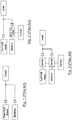
- Figure 1 depicts the connection of a fuel cell stack and a battery with a simple load sharing device.
- the hybridization occurs at the voltage the battery sits in, causing the fuel cells to work at low efficient ranges.
- This kind of hybrid power system presents several drawbacks:
- connection scheme is depicted in Figure 2 .
- This type of connection employs a DC/DC step-up converter placed between the battery and the load sharing device. The voltages at the load sharing device are then matched by an external controller changing the setting of the step-up converter output voltage.
- FIG. 3 illustrates another connection scheme using electronic switching between batteries and fuel cells.
- This solution although more efficient, has a main disadvantage: the battery and the fuel cell have practically no range in which both are delivering power to the load at the same time, making it useful only as a backup power source system.
- This topology presents other disadvantages:
- Patent document US6555928-B1 discloses a hybrid power source and a power source control method for hybrid-driven vehicles, the hybrid power source comprising a fuel cell and a battery.
- the fuel cell is not prepared to work efficiently for the whole battery range.
- Patent document US2009181269-A1 discloses a fuel cell which can work efficiently for low power operation, using a plurality of sub-stacks which are fed independently with separate channels for hydrogen inflow. As a consequence, this fuel cell requires a great amount of costly modifications in the fuel cell, including many supply inlets (six, in particular) in one of the end plates, along with valves to operate each hydrogen channel and detectors to monitor the temperature of the gas in each channel.
- Fuel cells are normally presented in serialized single cells forming stacks, having a conductive plate at each end (i.e. end plates), and providing a voltage which is the sum of all the voltages of the single cells.
- the present disclosure refers to a hybrid power system to feed a load, wherein the hybrid power system comprises a battery, a control unit and a fuel cell stack with one or more middle conductive plates to tap the fuel cell stack at an intermediate voltage, making it advantageous for both the physical condition of the fuel cell stack itself and the application with batteries in hybrid power systems.
- the fuel cell stack allows producing more power, and at the same time there is less damage (and consequently longer life) for the fuel cell.
- conductive used in the present disclosure (e.g. "conductive end plate”, “conductive middle plate”) refers to “electrically conductive”.
- the fuel cell stack used in the hybrid power system comprises first and second conductive end plates with contact terminals, a plurality of fuel cells electrically connected in series and stacked between the conductive end plates, and at least one conductive middle plate with at least one contact terminal. Each conductive middle plate is stacked between adjacent fuel cells.
- the fuel cell stack may also comprise an end plate placed at each end of the fuel cell stack.
- the control unit is configured to select an operating voltage of the fuel cell stack obtained from the contact terminals of the at least one conductive middle plate and conductive end plates when the hybrid power system is feeding the load.
- the control unit is configured to select the operating voltage of the fuel cell stack depending on the values of the voltages at the contact terminals of the fuel cell stack.
- the voltage of the battery may also be considered when selecting the operating voltage.
- the control unit is further configured to compare the selected operating voltage of the fuel cell stack feeding the load with a safe lower limit, and if the current operating voltage is inferior to the safe lower limit, select a lower operating voltage, obtained from the contact terminals of the at least one conductive middle plate and conductive end plates, to feed the load.
- the fuel cell stack may comprise a plurality of fuel cell sub-stacks connected in series, each fuel cell sub-stack comprising at least one fuel cell.
- Each conductive middle plate is configured to be stacked between a pair of adjacent fuel cell sub-stacks.
- a fuel cell sub-stack may comprise a plurality of bipolar plates and at least one fuel cell, wherein each fuel cell is stacked between a pair of bipolar plates.
- the fuel cell stack comprises a plurality of bipolar plates, each bipolar plate being arranged between adjacent fuel cells.
- Each conductive middle plate is configured to be stacked in contact with a bipolar plate and the cathode or anode of a fuel cell.
- the fuel cell stack comprises a plurality of bipolar plates, each bipolar plate being arranged between adjacent fuel cells, and each conductive middle plate being configured to be stacked in contact with the cathode of a fuel cell and the anode of an adjacent fuel cell.
- the conductive middle plate has a double function: acting as a bipolar plate and at the same time providing contact terminals to allow accessing different voltage levels.
- Each contact terminal may comprise one or more conductive tabs protruding from the fuel cell stack.
- the conductive middle plate may comprise a bipolar plate and one or more conductive tabs protruding from the bipolar plate.
- the hybrid power system may further comprise a plurality of switches connecting the load with the contact terminals of the conductive middle plate and at least one contact terminal of the conductive end plates of the fuel cell stack, wherein the control unit is configured to operate the switches to select the operating voltage of the fuel cell stack used to feed the load.
- the hybrid power system may also comprise a battery switch connecting the load with the battery, wherein the control unit is configured to operate the battery switch depending on the values of the voltage of the battery and the operating voltage of the fuel cell stack.
- one of the conductive end plates may be connected to ground and the operating voltage may be defined as the electric tension between a contact terminal of a conductive middle plate (or the contact terminal of the other conductive end plate, not connected to ground) and ground.
- the operating voltage may be defined as the electric tension between two different contact terminals of the fuel cell stack (in that case, there are multiple different possible combinations).
- a further aspect of the present invention also refers to a method to control a hybrid power system comprising a battery and a fuel cell stack according to the present disclosure.
- the method comprises selecting an operating voltage of the fuel cell stack obtained from contact terminals of the conductive end plates and at least one conductive middle plate stacked between adjacent fuel cells when the hybrid power system (90) is feeding a load.
- the operating voltage of the fuel cell stack is selected depending on the values of the voltages at the contact terminals of the fuel cell stack.
- the voltage of the battery may also be considered.
- the method further comprises determining if the selected operating voltage of the fuel cell stack feeding the load is lower than a safe lower limit, and in that case selecting a lower operating voltage, obtained from the contact terminals of the at least one conductive middle plate and conductive end plates, to feed the load.
- the safe lower limit is a value proportional to the number of active fuel cells feeding the load.
- the method may also comprise determining if the voltage of the entire fuel cell stack is lower than the voltage of the battery, and in that case activating a battery switch to feed the load with energy provided by the battery.
- the fuel cell stack is made up of a plurality of fuel cell sub-stacks connected in series, and a conductive middle plate placed between each pair of fuel cell sub-stacks and in electrical contact with each sub-stack.
- the fuel cell stack provides power by accessing contact terminals of the end plates and/or the middle plates.
- a hybrid power system is made up one or more batteries and a fuel cell stack. As the batteries weaken due to a heavy electrical load, the hybrid power system switches access to a conductive middle plate of the fuel cell stack. Switching to a middle plate voltage will result in an intermediate voltage. The system is now able to provide more power without causing damage to the fuel cell.
- a middle-plate configuration permits merging fuel cell power when the battery voltage is low. It also ensures that the fuel cell is able to deliver its nominal power without penalizing the battery due to overheating. In case the battery starts depleting (for example, because the power demand needs more than what the fuel cell stack can deliver by itself) access to the fuel cell stack can be switched to the middle plate, so it would continue to deliver power without incurring damages, resulting in longer operating life for the fuel cell.
- the fuel cell stack using this particular configuration is also a simple and cost-effective solution.
- the cost of placing middles plate in a fuel cell stack is practically negligible compared to the price of the fuel cell stack itself.
- the switching logic that selects which plate to use is simpler, smaller, cheaper, more efficient than a DC/DC step-up converter. Additional elements that a step-up converter would require, such as heatsinks and fans, can also be spared.
- the fuel cell stack used in the hybrid power system of the present disclosure is easier to debug; in this sense, the maintenance costs would also be reduced due of its simplicity and because the lifespan of the fuel cells would be extended. Allowing the fuel cell to work in its maximum efficiency range avoids or reduces the space needed for conditioning purposes (heatsinks, fans, mounting brackets, etc.) which could reduce the payload bay.
- the hybrid power system may be installed and applied to any device or vehicle using fuel cells: fuel cell powered airborne vehicles, fuel cell powered cars, fuel cell powered boats or even fuel cell powered stationary equipment.
- the present disclosure refers to a hybrid power system comprising a fuel cell stack used in combination with batteries.
- Figure 5 illustrates an embodiment of a fuel cell stack 1 according to the present disclosure.
- the fuel cell stack 1 comprises a first conductive end plate 2, acting as cathode, and a second conductive end plate 3, acting as anode, placed at both ends of the stack.
- Each end plate (2, 3) is provided with at least one contact terminal.
- the contact terminal may be, for instance, a metallic part attached to the end plate, an integral part of the end plate itself or an extension of the end plate or, as in the embodiment shown in Figure 5 , implemented as one or more conductive tabs 4 or solder lugs extending from each conductive end plate.
- the voltage between contact terminals of first end plate 2 and second end plate 3 is the maximum voltage generated by the fuel cell stack 1.
- the fuel cell stack 1 also comprises a plurality of fuel cells 7 arranged in two or more fuel cell sub-stacks 5 placed between the end plates (2, 3). Within each of the sub-stacks 5 the fuel cells are electrically connected in series with one another. The fuel cell sub-stacks 5 are in turn connected in series, oriented in the same direction and maintaining the same polarity. Each fuel cell sub-stack 5 comprises at least one fuel cell 7. In the embodiment of Figure 5 , the fuel cell stack 1 comprises two sub-stacks 5 made up of five individual fuel cells 7 and two single fuel cells 7, respectively.
- At least one conductive middle plate 6 is stacked between a pair of fuel cell sub-stacks 5.
- a middle plate 6 is located between the two adjacent sub-stacks 5.
- Each middle plate 6 is also provided with at least one contact terminal (in the embodiment of Figure 5 implemented as one or more conductive tabs 11, flaps or solder lugs extending from each conductive middle plate 6, protruding from the fuel cell stack 1) through which an intermediate voltage, lower than the maximum voltage of the fuel cell stack 1, can be obtained.
- the fuel cell stack 1 may further comprise an end plate (13, 14) located at each end of the stack.
- the end plates (13, 14) are normally made of glass fiber, although they can be manufactured using other materials, such as plastics or even metallic materials. These end plates (13, 14) are used to compact the stack, usually using a threaded rod or very long screws from one end plate to the other, which can be tighten to improve the contact between adjacent fuel cells so that all the ducts (hydrogen and oxygen) are perfectly sealed.
- a fuel cell sub-stack 5 comprises one or more fuel cells 7 separated by bipolar plates (not shown in Figure 5 ).
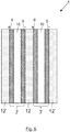
- Figure 6 depicts, in a schematic side view, the different layers forming a fuel cell sub-stack 5.
- the fuel cell sub-stack 5 comprises two fuel cells 7.
- Each fuel cell 7 is represented with a block diagram, formed by a cathode 8, an anode 9 and a layer of an electrolyte 10.
- each fuel cell 7 is stacked between a pair of bipolar plates (12, 12').
- each sub-stack 5 the inner bipolar plates 12 which are located between two adjacent fuel cells 7 form the positive side of one fuel cell 7 and the negative side of an adjacent fuel cell 7, as observed in the central bipolar plate 12 of Figure 6 .
- the use of bipolar plates permits all of the fuel cells 7 in a sub-stack 5 to be electrically interconnected in series with one another.
- the fuel cell sub-stack 5 may also comprise outer bipolar plates 12' located at both ends. In another embodiment, one or both of these outer bipolar plates 12' may be absent.
- Figure 7 represents a schematic layout of the fuel cell stack 1 of Figure 5 . All the fuel cells 7 within a sub-stack 5 are connected in series. Both sub-stacks are also connected in series, with the same orientation, through respective outer bipolar plates 12' which electrically connect the anode 9 of an outer fuel cell 7 of a sub-stack 5 with the cathode 8 of an outer fuel cell 7 of the other sub-stack 5.
- a plurality of middle plates 6 can be stacked to gain access to additional intermediate voltages.
- Figure 8 depicts a fuel cell stack 1 with three sub-stacks 5 (with three, one and two fuel cells, respectively) and two middle plates (a first middle plate 6 and a second middle plate 6') separating adjacent sub-stacks 5.
- the fuel cells of the stack 1 can also be dimensioned to work in its most efficient range, achieving longer endurance for a given amount of fuel.
- the most efficient voltage taking into account not only electric efficiency but fuel utilization efficiency
- the battery is not depleting itself because the overall voltage (35V) is still out of the sharing region.
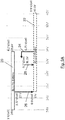
- Figure 9A shows the working voltage range of an 8-cell battery and a 45-cell fuel cell stack, and how the power would be shared in a hybrid system with a fuel cell without middle plate.
- the bar 20 shows the range of the battery which, when fully charged, has a voltage of 4.2 V/cell (i.e. a total voltage of 33.6 V, right side of the bar 20). As the battery is being depleted, the voltage provided per cell is reduced, down to 3 V/cell (i.e. a total voltage of 24 V, left side of the bar 20).
- the bar 22 corresponds to the voltage range of the fuel cell. In open circuit, without a load, the voltage at the terminals is around 0.9 V/cell (adding up to 40.5 V).
- the broken arrow 24 indicates the voltage of the fuel cell stack (0.75 V/cell) from which the fully charged battery (33.6 V) would begin to complement the fuel cell stack through a hybrid system (when both voltages are equalized).
- the arrow 26 indicates the point at which the fuel cell would be at its lower voltage limit (0.6 V/cell) before risking damage. At that point, the battery can no longer be discharged, because it would force the fuel cell to fall below its lower voltage limit. At that point it would be convenient to switch to a middle plate of the fuel cell stack to continue discharging the battery.
- the arrow 28 simply indicates an intermediate voltage in which the fuel cell stack is working normally (switching to a middle plate is not required at this point).
- Figure 9B shows the voltage ranges of an 8-cell lithium battery and the voltage range of a 50-cell fuel cell (bar 30) with two different middle plates placed at a position of 45-cell (bar 32) and 40-cell (bar 34), respectively.
- the first middle plate When the first middle plate is selected in the fuel cell stack, it works as a 45-cell fuel cell stack, whereas if the second middle plate is selected, the fuel cell stack works as a 40-cell fuel cell stack.
- Figure 9B shows how as progressively switching to the middle plate corresponding to the 45-cell first and to the middle plate corresponding to the 40-cell later, the fuel cell stack can correctly and progressively adapt to the current voltage of the battery.
- the fuel cell stack 1 of the present disclosure also allows, when applied to a hybrid power system, a perfect matching for batteries that simplifies electronics.
- Figure 9B shows how using a single middle-plate configuration placed on a 40-cell stack would let merging fuel cell power when the battery is below 30V. It also would ensure that the fuel cell is able to deliver its nominal power without penalizing the battery when it is configured for 50 cells. In case the battery starts depleting (for example, because the power demand needs more than what the fuel cell can deliver by itself) when the battery reaches the 30V limit, the fuel cell can be switched to its middle plate, so it would continue to deliver power without incurring damages.
- the fuel cell stack 1 also allows sharing hybrid power with the battery for the whole battery range. In case a prolonged sharing is required, the battery can fully deplete while still having a contribution from the fuel cell.
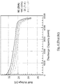
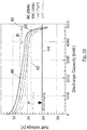
- Figure 10 depicts the cell discharge curve of Figure 4 for different discharge rates C of a 5000mAh battery cell.
- This figure also includes three dotted lines (40, 42, 44) which indicate the voltage of three different fuel cell stacks (40-cell, 45-cell and 50-cell fuel stacks) when subjected to their nominal load at 0.6 V/cell. Below this voltage, the fuel cell stack is being stressed. The arrows indicate the region in which in which the batteries can complement the fuel cell stack and the hybrid system can therefore properly work. As the batteries are being discharged, their voltage drop. When the battery voltage falls below a dotted line, the fuel cell stack corresponding to the dotted line will be put under stress since it will be forced to work under the nominal voltage of 0.6 V/cell.
- the voltage of the battery cell with a discharge rate of 5C would be reached at point 46 when they have only spent 2000 mAh of their total 5000 mAh (less than half their capacity).
- the voltage of the 5C battery cell drops below the upper dotted line 40, it would be advisable to use the first middle plate corresponding to the 45-cell configuration. From that point, the 5C battery cell would be effectively connected to a 45-cell fuel cell stack.
- the voltage of the 5C battery cell drops below the middle dotted line 42 (at point 48), it would be advisable to use the second middle plate corresponding to the 40-cell configuration.
- regions above each dotted line in Figure 10 correspond to regions of battery voltage in which hybridization of the two power sources can be made without stressing the fuel cell stack.
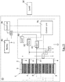
- the switching process to a determined conductive middle plate (6, 6') is performed by a control unit 70, as shown in the exemplary embodiment of Figure 11 .
- the control unit 70 manages the hybridization between a battery 50 and a fuel cell stack 1 equipped with two middle plates (6, 6').
- the battery 50 must be understood as an electric energy source comprising one or more electrochemical cells (battery 50 may be formed by an association of batteries connected in series and/or parallel).
- the hybrid power system 90 formed by the battery 50 the fuel cell stack 1 and the control unit, feeds a load 60.
- the positive pole of the fuel cell stack 1 (i.e. the first conductive end plate 2) is connected directly to the load 60 but controlled by a first switch 80 that can be opened or closed through the control unit 70.
- the negative pole of the fuel cell stack 1 (i.e. the second conductive end plate 3) is connected to ground.
- Each middle plate (6, 6') is also directly connected to the load 60 through a middle plate switch (in the example of Figure 11 , first middle plate switch 82 and second middle plate switch 84), which in turn is also operated by the control unit 70.
- the power output of the fuel cell stack 1 has at least two control switches, a first switch 80 for selecting the entire fuel cell stack and at least one middle plate switch (82, 84) for selecting a reduced fuel cell stack formed by one or more sub-stacks 5.
- the battery 50 is connected to the load 60 and to the output of the fuel cell stack 1 through a battery switch 86 also operated by the control unit 70.
- the control unit 70 receives readings of the voltage of the battery (Vbatt), the voltage of the entire fuel cell stack (V1) and the voltages of the substacks (V2, V3). Depending on the values of these voltages, the control unit 70 will activate one or another switch to allow power flow to the load 60 from:
- FIG 12 depicts an embodiment of a switching process control 100 for the hybrid power system 90 of Figure 11 .
- the switching process control 100 starts with the activation of the first switch 80 (switch 1), to feed the load 60 with only the power output by the entire fuel cell stack 1.
- the unit control 70 checks 104 if the voltage of the entire fuel cell stack (V1) is lower than the voltage of the battery (Vbatt). In that case, the control unit 70 activates 106 the battery switch 86 to complement the fuel cell stack 1 with the power provided by the battery 50. On the contrary, if the voltage of the entire fuel cell stack (V1) is higher than the voltage of the battery (Vbatt), the entire fuel cell stack continues to feed the load 60 alone (first switch 80 remains closed 102, battery switch 86 remains opened 108).
- the control unit 70 checks 110 if the voltage of the entire fuel cell stack (V1) is lower than a safe lower limit.
- the safe lower limit corresponds to a cell limit voltage (e.g. 0.6 V) multiplied by the number of cells X of the entire fuel cell stack 1 (50 cells in the example of Figure 9B and Figure 10 ), to check if the voltage of each fuel cell drops below the cell limit voltage of 0.6 V. If the voltage is in fact smaller, in step 112 the effective size of the fuel cell stack is reduced by opening the first switch 80 (switch 1) and closing the first middle plate switch 82 (switch 2), which is connected to the first middle plate 6.
- control unit 70 goes back to step 104 to check if the battery is needed, as there may have been a reduction on the battery voltage (Vbatt) that would make the additional power from the battery unnecessary.
- Vbatt battery voltage
- the basic process for one single middle plate 6 ends at step 112, running iteratively to check in the first instance if the battery 50 is required and, in subsequent steps, if switching to another middle plate 6' is needed, depending on the battery voltage (Vbatt) and the voltage of the effective fuel cell stack.
- the effective fuel cell stack is formed by the fuel cells stacked between the second end plate 3 and the active middle plate (i.e. the middle plate which associated switch has been activated).
- the control unit 70 checks 114 if the voltage of the reduced fuel cell stack (voltage V2 corresponding to the first middle plate) is lower than a safe lower limit for the reduced stack (a cell limit voltage of 0.6 V multiplied by the number of cells Y of the reduced fuel cell stack formed by 45 cells in the example of Figure 9B and Figure 10 ). In that case, in step 116 the effective size of the fuel cell stack is reduced again by activating the second middle plate switch 86 (switch 3), which is connected to the second middle plate 6', and opening the first middle plate switch 82. However, if the effective fuel cell stack has not yet reached the threshold of 0.6 V per cell, the control unit 70 goes back to step 110 to check if it is possible to return to the first middle plate 6 (i.e. an effective fuel cell stack with more cells).
- the control unit 70 checks if the voltage corresponding to the active middle plate is lower than a threshold (e.g. 0.6 V per cell), and in that case connecting the following middle plate to the load 60.
- a threshold e.g. 0.6 V per cell
- the control unit 70 first checks if it is necessary to complement the entire fuel cell stack 1 with the battery 50 and, if so, the control unit 70 keeps checking if it is necessary to select a subsequent middle plate such that the voltage of the reduced fuel cell stack is greater than 0.6 volts per cell. Each time the cell voltage of the effective fuel cell stack is proved to be higher than 0.6 V/cell, the algorithm advances in the reverse direction to check if it is possible to return to an upper stack (i.e. an effective fuel cell stack with more cells), and even if it viable to disconnect 108 the battery 50.
- an upper stack i.e. an effective fuel cell stack with more cells
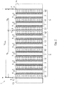
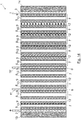
- Figure 13 depicts another embodiment of the fuel cell stack 1 with several conductive middle plates (6, 6') with one or more contact terminals (11, 11').
- the fuel cell stack 1 is not formed by a succession of the sub-cell stacks 5 of Figure 6 .
- the fuel cell stack 1 comprises a plurality of individual fuel cells 7 connected in series and a bipolar plate 12 arranged in between consecutive fuel cells 7.
- the conductive middle plates (6, 6') are arranged between adjacent fuel cells 7, and more specifically, between the bipolar plate 12 in contact with a fuel cell 7 and the cathode 8 of an adjacent fuel cell 7. Similarly, the conductive middle plates (6, 6') may be arranged between the bipolar plate 12 in contact with a fuel cell 7 and the anode 9 of an adjacent fuel cell 7.
- the conductive middle plate (6, 6') may replace a bipolar plate 12, such that the conductive middle plate (6, 6') provides the function of a bipolar plate 12 and also provides a contact terminal (11, 11') through which a control unit 70 may select a different voltage of the fuel cell stack 1.
- the conductive middle plate (6, 6') is stacked in contact with the cathode (8) of a fuel cell (7) and with the anode (9) of an adjacent fuel cell (7).
- the conductive middle plate (6, 6') may be formed by a bipolar plate 12 incorporating least one contact terminal (e.g. one or more conductive tabs 11, flaps or solder lugs) extending or protruding from the bipolar plate 12, allowing to set up a wire connection (for instance, through welding).
Landscapes
- Engineering & Computer Science (AREA)
- Life Sciences & Earth Sciences (AREA)
- Sustainable Development (AREA)
- Sustainable Energy (AREA)
- Chemical & Material Sciences (AREA)
- Chemical Kinetics & Catalysis (AREA)
- Electrochemistry (AREA)
- General Chemical & Material Sciences (AREA)
- Manufacturing & Machinery (AREA)
- Fuel Cell (AREA)
- Power Engineering (AREA)
- Secondary Cells (AREA)
Claims (14)
- Hybridantriebssystem zur Versorgung einer Last (60), wobei das Hybridantriebssystem (90) eine Batterie (50), einen Brennstoffzellenstapel (1) und eine Steuereinheit (70) aufweist, wobei der Brennstoffzellenstapel (1) aufweist:eine erste (2) und zweite (3) leitende Endplatten mit Kontaktanschlüssen (4) und eine Vielzahl von Brennstoffzellen (7), die elektrisch in Reihe geschaltet und zwischen den leitenden Endplatten (2, 3) gestapelt sind;dadurch gekennzeichnet, dass der Brennstoffzellenstapel (1) ferner mindestens eine leitende Mittelplatte (6, 6') mit mindestens einem Kontaktanschluss (11, 11') aufweist, wobei jede leitende Mittelplatte (6, 6') zwischen benachbarte Brennstoffzellen (7) gestapelt ist; wobei die Steuereinheit (70) dazu eingerichtet ist,eine Betriebsspannung des Brennstoffzellenstapels (1) auszuwählen, die von den Kontaktanschlüssen (4, 11, 11') der mindestens einen leitenden Mittelplatte (6, 6') und der leitenden Endplatte (2, 3) erhalten wird, wenn die Hybridantriebssystem (90) die Last (60) versorgt, wobei die Steuereinheit (70) dazu eingerichtet ist, die Betriebsspannung des Brennstoffzellenstapels (1) in Abhängigkeit von den Werten der Spannungen (V1, V2, V3) an den Kontaktanschlüssen (4, 11, 11') des Brennstoffzellenstapels (1) auszuwählen;die ausgewählte Betriebsspannung des Brennstoffzellenstapels (1), der die Last (60) versorgt, mit einer sicheren unteren Grenze zu vergleichen (110, 114);Wenn die aktuelle Betriebsspannung unter der sicheren Untergrenze liegt, wird zur Versorgung der Last (60) eine niedrigere Betriebsspannung gewählt (112, 116), die von den Kontaktanschlüssen (4, 11, 11') der mindestens einen leitenden Mittelplatte (6, 6') und der leitenden Endplatten erhalten wird.
- Hybridantriebssystem nach Anspruch 1, wobei die sichere Untergrenze ein Wert ist, der proportional zur Anzahl der aktiven Brennstoffzellen ist, die die Last (60) versorgen.
- Hybridantriebssystem nach einem der vorhergehenden Ansprüche, das ferner eine Mehrzahl von Schaltern aufweist (82, 84, 86), die die Last (60) mit den Kontaktanschlüssen (11, 11') der leitenden Mittelplatte (6, 6') und mindestens einen Kontaktanschluss (4) der leitenden Endplatten (2, 3) des Brennstoffzellenstapels (1) verbinden, wobei die Steuereinheit (70) dazu eingerichtet ist, die Schalter (82, 84, 86) zu betätigen, um die Betriebsspannung des Brennstoffzellenstapels (1) auszuwählen, der zur Versorgung der Last verwendet wird (60).
- Hybridantriebssystem nach einem der vorhergehenden Ansprüche, ferner umfassend einen Batterieschalter (86), der die Last (60) mit der Batterie (50) verbindet, wobei die Steuereinheit (70) dazu eingerichtet ist, den Batterieschalter (86) in Abhängigkeit von den Werten der Spannung (Vbatt) der Batterie (50) und der Betriebsspannung des Brennstoffzellenstapels (1) zu betreiben.
- Hybridantriebssystem nach einem der Ansprüche 1 bis 4, wobei der Brennstoffzellenstapel (1) mehrere in Reihe geschaltete Brennstoffzellen-Teilstapel (5) aufweist, wobei jeder Brennstoffzellen-Teilstapel (5) mindestens eine Brennstoffzelle (7) aufweist und wobei jede leitende Mittelplatte (6, 6') dazu eingerichtet ist, zwischen einem Paar benachbarter Brennstoffzellen-Teilstapel (5) gestapelt zu werden.
- Hybridantriebssystem nach Anspruch 5, wobei jeder Brennstoffzellen-Teilstapel (5) des Brennstoffzellenstapels (1) eine Mehrzahl von Bipolarplatten (12, 12') und mindestens eine Brennstoffzelle (7) aufweist, wobei jede Brennstoffzelle (7) zwischen einem vom Paar Bipolarplatten (12, 12') gestapelt ist.
- Hybridantriebssystem nach einem der Ansprüche 1 bis 4, wobei der Brennstoffzellenstapel (1) ferner eine Mehrzahl von Bipolarplatten (12) aufweist, wobei jede Bipolarplatte (12) zwischen benachbarten Brennstoffzellen (7) angeordnet ist, wobei jede leitende Mittelplatte (6, 6') dazu eingerichtet ist, in Kontakt mit einer Bipolarplatte (12) und der Kathode (8) oder Anode (9) einer Brennstoffzelle (7) gestapelt zu werden.
- Hybridantriebssystem nach einem der Ansprüche 1 bis 4, wobei der Brennstoffzellenstapel (1) ferner eine Mehrzahl von Bipolarplatten (12) aufweist, wobei jede Bipolarplatte (12) zwischen benachbarten Brennstoffzellen (7) angeordnet ist, wobei jede leitende Mittelplatte (6, 6') dazu eingerichtet ist, in Kontakt mit der Kathode (8) einer Brennstoffzelle (7) und der Anode (9) einer benachbarten Brennstoffzelle (7) gestapelt zu werden.
- Hybridantriebssystem nach einem der vorhergehenden Ansprüche, wobei jeder Kontaktanschluss (11, 11') der leitenden Mittelplatte (6, 6') des Brennstoffzellenstapels (1) einen oder mehrere Kontaktanschlüssen aufweist, die aus dem Brennstoffzellenstapel (1) herausragen.
- Hybridantriebssystem nach Anspruch 9, wobei die leitende Mittelplatte (6, 6') des Brennstoffzellenstapels (1) eine Bipolarplatte (12) und eine oder mehrere Kontaktanschlüssen (11, 11') aufweist, die aus der Bipolarplatte (12) herausragen.
- Hybridantriebssystem nach einem der vorhergehenden Ansprüche, wobei der Brennstoffzellenstapel (1) ferner eine Endplatte (13, 14) aufweist, die an jedem Ende des Brennstoffzellenstapels (1) angeordnet ist.
- Verfahren zum Steuern eines Hybridantriebssystems mit einer Batterie (50) und einem Brennstoffzellenstapel (1) nach einem der Ansprüche 1 bis 11;
dadurch gekennzeichnet, dass das Verfahren aufweist:eine Betriebsspannung des Brennstoffzellenstapels (1) auszuwählen, die von Kontaktanschlüssen (4, 11, 11') der leitenden Endplatten (2, 3) und mindestens einer leitenden Mittelplatte (6, 6') erhalten wird, die zwischen benachbarten Brennstoffzellen (7) gestapelt sind, wenn das Hybridantriebssystem eine Last (1) versorgt, wobei die Betriebsspannung des Brennstoffzellenstapels (1) in Abhängigkeit von den Werten der Spannungen (V1, V2, V3) an den Kontaktanschlüssen (4, 11, 11') des Brennstoffzellenstapels (1) gewählt wird;die ausgewählte Betriebsspannung des Brennstoffzellenstapels (1), der die Last versorgt (60), mit einer sicheren unteren Grenze zu vergleichen (110, 114); wenn die aktuelle Betriebsspannung unter der sicheren Untergrenze liegt, wird zur Versorgung der Last (60) eine niedrigere Betriebsspannung gewählt (112, 116), die von den Kontaktanschlüssen (4, 11, 11') der mindestens einen leitenden Mittelplatte (6, 6') und der leitenden Endplatten erhalten wird. - Verfahren nach Anspruch 12, wobei die sichere Untergrenze ein Wert ist, der proportional zu der Anzahl von aktiven Brennstoffzellen ist, die die Last (60) versorgen.
- Verfahren nach Anspruch 12 oder 13, wobei das Verfahren aufweist:
die Spannung des gesamten Brennstoffzellenstapels (V1) mit der Spannung der Batterie (Vbatt) zu vergleichen (104); wenn die Spannung des gesamten Brennstoffzellenstapels (V1) niedriger als die Spannung der Batterie (Vbatt) ist, wird ein Batterieschalter (86) aktiviert (106), um die Last (60) mit der von der Batterie (50) bereitgestellten Energie zu versorgen.
Priority Applications (7)
| Application Number | Priority Date | Filing Date | Title |
|---|---|---|---|
| EP16382626.6A EP3340355B1 (de) | 2016-12-20 | 2016-12-20 | Hybrides leistungssystem und steuerverfahren dafür |
| ES16382626T ES2789364T3 (es) | 2016-12-20 | 2016-12-20 | Sistema de alimentación híbrido y método de control del mismo |
| JP2017210242A JP7115835B2 (ja) | 2016-12-20 | 2017-10-31 | 高度ハイブリッド電力システム向け燃料電池スタック |
| CA2985285A CA2985285C (en) | 2016-12-20 | 2017-11-10 | Hybrid power system and control method thereof |
| US15/837,915 US20180175400A1 (en) | 2016-12-20 | 2017-12-11 | Fuel cell stack for enhanced hybrid power systems |
| CN201711371436.1A CN108206296B (zh) | 2016-12-20 | 2017-12-19 | 燃料电池堆、混合电力系统及其控制方法 |
| KR1020170175173A KR102520568B1 (ko) | 2016-12-20 | 2017-12-19 | 강화된 하이브리드 전력 시스템들을 위한 연료 전지 스택 |
Applications Claiming Priority (1)
| Application Number | Priority Date | Filing Date | Title |
|---|---|---|---|
| EP16382626.6A EP3340355B1 (de) | 2016-12-20 | 2016-12-20 | Hybrides leistungssystem und steuerverfahren dafür |
Publications (2)
| Publication Number | Publication Date |
|---|---|
| EP3340355A1 EP3340355A1 (de) | 2018-06-27 |
| EP3340355B1 true EP3340355B1 (de) | 2020-02-05 |
Family
ID=57583107
Family Applications (1)
| Application Number | Title | Priority Date | Filing Date |
|---|---|---|---|
| EP16382626.6A Active EP3340355B1 (de) | 2016-12-20 | 2016-12-20 | Hybrides leistungssystem und steuerverfahren dafür |
Country Status (7)
| Country | Link |
|---|---|
| US (1) | US20180175400A1 (de) |
| EP (1) | EP3340355B1 (de) |
| JP (1) | JP7115835B2 (de) |
| KR (1) | KR102520568B1 (de) |
| CN (1) | CN108206296B (de) |
| CA (1) | CA2985285C (de) |
| ES (1) | ES2789364T3 (de) |
Families Citing this family (3)
| Publication number | Priority date | Publication date | Assignee | Title |
|---|---|---|---|---|
| JP3132743B2 (ja) | 1995-03-15 | 2001-02-05 | 鹿島建設株式会社 | 伸縮ブームの異常電圧自動減衰装置 |
| JP2925070B2 (ja) | 1996-02-29 | 1999-07-26 | 鹿島建設株式会社 | クレーンの異常電圧減衰装置 |
| JP7438256B2 (ja) * | 2022-03-31 | 2024-02-26 | 本田技研工業株式会社 | 電源システム、制御方法、およびプログラム |
Family Cites Families (10)
| Publication number | Priority date | Publication date | Assignee | Title |
|---|---|---|---|---|
| JP2001095107A (ja) * | 1999-09-21 | 2001-04-06 | Yamaha Motor Co Ltd | ハイブリッド駆動式移動体の電源制御方法 |
| JP2002324562A (ja) | 2001-04-27 | 2002-11-08 | Mitsubishi Heavy Ind Ltd | 燃料電池発電システムの運転方法及び燃料電池発電システム |
| JP4752175B2 (ja) * | 2003-06-05 | 2011-08-17 | ソニー株式会社 | 燃料電池 |
| US20050142407A1 (en) * | 2003-12-26 | 2005-06-30 | Fuller Thomas F. | Start up cascaded fuel cell stack |
| US7078119B2 (en) * | 2004-06-29 | 2006-07-18 | Nissan Motor Co., Ltd. | Fuel cell system and method for generating electricity from a fuel cell system comprising a fuel cell stack divided into sub-tracks |
| US20060204815A1 (en) * | 2005-03-10 | 2006-09-14 | Angstrom Power Incorporated | Cell stack having sub-stacks with opposite orientations |
| EP2037526A4 (de) * | 2006-05-08 | 2011-11-30 | Panasonic Corp | Brennstoffzellenstapel, brennstoffzellensystem und brennstoffzellensystem-betriebsverfahren |
| AT505914B1 (de) * | 2008-03-28 | 2009-05-15 | Fronius Int Gmbh | Verfahren und vorrichtung zum abschalten einer brennstoffzelle |
| TW201128845A (en) * | 2010-02-12 | 2011-08-16 | Chung Hsin Elec & Mach Mfg | Parallel fuel cell electrical power system |
| GB2531510A (en) * | 2014-10-15 | 2016-04-27 | Intelligent Energy Ltd | Fuel cell and battery |
-
2016
- 2016-12-20 EP EP16382626.6A patent/EP3340355B1/de active Active
- 2016-12-20 ES ES16382626T patent/ES2789364T3/es active Active
-
2017
- 2017-10-31 JP JP2017210242A patent/JP7115835B2/ja active Active
- 2017-11-10 CA CA2985285A patent/CA2985285C/en active Active
- 2017-12-11 US US15/837,915 patent/US20180175400A1/en not_active Abandoned
- 2017-12-19 CN CN201711371436.1A patent/CN108206296B/zh active Active
- 2017-12-19 KR KR1020170175173A patent/KR102520568B1/ko active Active
Non-Patent Citations (1)
| Title |
|---|
| None * |
Also Published As
| Publication number | Publication date |
|---|---|
| CA2985285A1 (en) | 2018-06-20 |
| CA2985285C (en) | 2022-10-04 |
| JP7115835B2 (ja) | 2022-08-09 |
| KR20180071975A (ko) | 2018-06-28 |
| JP2018142533A (ja) | 2018-09-13 |
| CN108206296A (zh) | 2018-06-26 |
| US20180175400A1 (en) | 2018-06-21 |
| EP3340355A1 (de) | 2018-06-27 |
| KR102520568B1 (ko) | 2023-04-10 |
| ES2789364T3 (es) | 2020-10-26 |
| CN108206296B (zh) | 2022-10-25 |
Similar Documents
| Publication | Publication Date | Title |
|---|---|---|
| US6781343B1 (en) | Hybrid power supply device | |
| KR101893045B1 (ko) | 배터리용 충전 밸런싱 시스템 | |
| JP5571129B2 (ja) | ハイブリッド電源システム | |
| US10008861B2 (en) | Charge balancing in a battery | |
| JP6871854B2 (ja) | 燃料電池及び電池 | |
| EP3416224B1 (de) | Redox-flow-batterie mit spannungsbegrenzer | |
| EP3314718B1 (de) | Batterieausgleichsschaltung | |
| EP3340355B1 (de) | Hybrides leistungssystem und steuerverfahren dafür | |
| WO2021020029A1 (ja) | 車載用電源システム | |
| EP1967407B2 (de) | Hybride elektrische Stromquelle | |
| JP5503957B2 (ja) | 車両用電源装置 | |
| JP2009148110A (ja) | 充放電器とこれを用いた電源装置 | |
| US20230133126A1 (en) | Battery system and method for controlling a battery system | |
| EP3951970B1 (de) | Elektrodenanordnung für eine sekundärbatterie mit elektroden unterschiedlicher form | |
| GB2531509A (en) | Fuel cell assembly | |
| CN111052535A (zh) | 太阳能发电/蓄电单元以及太阳能发电/蓄电系统 | |
| US20150194835A1 (en) | Power control of batteries | |
| KR20190061847A (ko) | 배터리 시스템 및 상기 배터리 시스템의 배선 방법 | |
| WO2025262640A1 (en) | Energy storage | |
| CN117639062A (zh) | 储能转换控制电路、液流电池的控制电路及系统 |
Legal Events
| Date | Code | Title | Description |
|---|---|---|---|
| STAA | Information on the status of an ep patent application or granted ep patent |
Free format text: STATUS: EXAMINATION IS IN PROGRESS |
|
| PUAI | Public reference made under article 153(3) epc to a published international application that has entered the european phase |
Free format text: ORIGINAL CODE: 0009012 |
|
| 17P | Request for examination filed |
Effective date: 20161220 |
|
| AK | Designated contracting states |
Kind code of ref document: A1 Designated state(s): AL AT BE BG CH CY CZ DE DK EE ES FI FR GB GR HR HU IE IS IT LI LT LU LV MC MK MT NL NO PL PT RO RS SE SI SK SM TR |
|
| AX | Request for extension of the european patent |
Extension state: BA ME |
|
| GRAP | Despatch of communication of intention to grant a patent |
Free format text: ORIGINAL CODE: EPIDOSNIGR1 |
|
| STAA | Information on the status of an ep patent application or granted ep patent |
Free format text: STATUS: GRANT OF PATENT IS INTENDED |
|
| RIC1 | Information provided on ipc code assigned before grant |
Ipc: H01M 8/2465 20160101ALI20190702BHEP Ipc: H01M 16/00 20060101ALI20190702BHEP Ipc: H01M 8/0202 20160101ALI20190702BHEP Ipc: H01M 8/249 20160101ALI20190702BHEP Ipc: H01M 8/04537 20160101ALI20190702BHEP Ipc: H01M 8/04858 20160101AFI20190702BHEP |
|
| INTG | Intention to grant announced |
Effective date: 20190725 |
|
| GRAS | Grant fee paid |
Free format text: ORIGINAL CODE: EPIDOSNIGR3 |
|
| GRAA | (expected) grant |
Free format text: ORIGINAL CODE: 0009210 |
|
| STAA | Information on the status of an ep patent application or granted ep patent |
Free format text: STATUS: THE PATENT HAS BEEN GRANTED |
|
| AK | Designated contracting states |
Kind code of ref document: B1 Designated state(s): AL AT BE BG CH CY CZ DE DK EE ES FI FR GB GR HR HU IE IS IT LI LT LU LV MC MK MT NL NO PL PT RO RS SE SI SK SM TR |
|
| REG | Reference to a national code |
Ref country code: GB Ref legal event code: FG4D |
|
| REG | Reference to a national code |
Ref country code: AT Ref legal event code: REF Ref document number: 1230501 Country of ref document: AT Kind code of ref document: T Effective date: 20200215 |
|
| REG | Reference to a national code |
Ref country code: DE Ref legal event code: R096 Ref document number: 602016029090 Country of ref document: DE |
|
| REG | Reference to a national code |
Ref country code: IE Ref legal event code: FG4D |
|
| REG | Reference to a national code |
Ref country code: CH Ref legal event code: EP |
|
| REG | Reference to a national code |
Ref country code: NL Ref legal event code: MP Effective date: 20200205 |
|
| PG25 | Lapsed in a contracting state [announced via postgrant information from national office to epo] |
Ref country code: PT Free format text: LAPSE BECAUSE OF FAILURE TO SUBMIT A TRANSLATION OF THE DESCRIPTION OR TO PAY THE FEE WITHIN THE PRESCRIBED TIME-LIMIT Effective date: 20200628 Ref country code: RS Free format text: LAPSE BECAUSE OF FAILURE TO SUBMIT A TRANSLATION OF THE DESCRIPTION OR TO PAY THE FEE WITHIN THE PRESCRIBED TIME-LIMIT Effective date: 20200205 Ref country code: NO Free format text: LAPSE BECAUSE OF FAILURE TO SUBMIT A TRANSLATION OF THE DESCRIPTION OR TO PAY THE FEE WITHIN THE PRESCRIBED TIME-LIMIT Effective date: 20200505 Ref country code: FI Free format text: LAPSE BECAUSE OF FAILURE TO SUBMIT A TRANSLATION OF THE DESCRIPTION OR TO PAY THE FEE WITHIN THE PRESCRIBED TIME-LIMIT Effective date: 20200205 |
|
| REG | Reference to a national code |
Ref country code: LT Ref legal event code: MG4D |
|
| PG25 | Lapsed in a contracting state [announced via postgrant information from national office to epo] |
Ref country code: HR Free format text: LAPSE BECAUSE OF FAILURE TO SUBMIT A TRANSLATION OF THE DESCRIPTION OR TO PAY THE FEE WITHIN THE PRESCRIBED TIME-LIMIT Effective date: 20200205 Ref country code: SE Free format text: LAPSE BECAUSE OF FAILURE TO SUBMIT A TRANSLATION OF THE DESCRIPTION OR TO PAY THE FEE WITHIN THE PRESCRIBED TIME-LIMIT Effective date: 20200205 Ref country code: LV Free format text: LAPSE BECAUSE OF FAILURE TO SUBMIT A TRANSLATION OF THE DESCRIPTION OR TO PAY THE FEE WITHIN THE PRESCRIBED TIME-LIMIT Effective date: 20200205 Ref country code: IS Free format text: LAPSE BECAUSE OF FAILURE TO SUBMIT A TRANSLATION OF THE DESCRIPTION OR TO PAY THE FEE WITHIN THE PRESCRIBED TIME-LIMIT Effective date: 20200605 Ref country code: BG Free format text: LAPSE BECAUSE OF FAILURE TO SUBMIT A TRANSLATION OF THE DESCRIPTION OR TO PAY THE FEE WITHIN THE PRESCRIBED TIME-LIMIT Effective date: 20200505 Ref country code: GR Free format text: LAPSE BECAUSE OF FAILURE TO SUBMIT A TRANSLATION OF THE DESCRIPTION OR TO PAY THE FEE WITHIN THE PRESCRIBED TIME-LIMIT Effective date: 20200506 |
|
| PG25 | Lapsed in a contracting state [announced via postgrant information from national office to epo] |
Ref country code: NL Free format text: LAPSE BECAUSE OF FAILURE TO SUBMIT A TRANSLATION OF THE DESCRIPTION OR TO PAY THE FEE WITHIN THE PRESCRIBED TIME-LIMIT Effective date: 20200205 |
|
| REG | Reference to a national code |
Ref country code: ES Ref legal event code: FG2A Ref document number: 2789364 Country of ref document: ES Kind code of ref document: T3 Effective date: 20201026 |
|
| PG25 | Lapsed in a contracting state [announced via postgrant information from national office to epo] |
Ref country code: LT Free format text: LAPSE BECAUSE OF FAILURE TO SUBMIT A TRANSLATION OF THE DESCRIPTION OR TO PAY THE FEE WITHIN THE PRESCRIBED TIME-LIMIT Effective date: 20200205 Ref country code: CZ Free format text: LAPSE BECAUSE OF FAILURE TO SUBMIT A TRANSLATION OF THE DESCRIPTION OR TO PAY THE FEE WITHIN THE PRESCRIBED TIME-LIMIT Effective date: 20200205 Ref country code: RO Free format text: LAPSE BECAUSE OF FAILURE TO SUBMIT A TRANSLATION OF THE DESCRIPTION OR TO PAY THE FEE WITHIN THE PRESCRIBED TIME-LIMIT Effective date: 20200205 Ref country code: EE Free format text: LAPSE BECAUSE OF FAILURE TO SUBMIT A TRANSLATION OF THE DESCRIPTION OR TO PAY THE FEE WITHIN THE PRESCRIBED TIME-LIMIT Effective date: 20200205 Ref country code: SM Free format text: LAPSE BECAUSE OF FAILURE TO SUBMIT A TRANSLATION OF THE DESCRIPTION OR TO PAY THE FEE WITHIN THE PRESCRIBED TIME-LIMIT Effective date: 20200205 Ref country code: DK Free format text: LAPSE BECAUSE OF FAILURE TO SUBMIT A TRANSLATION OF THE DESCRIPTION OR TO PAY THE FEE WITHIN THE PRESCRIBED TIME-LIMIT Effective date: 20200205 Ref country code: SK Free format text: LAPSE BECAUSE OF FAILURE TO SUBMIT A TRANSLATION OF THE DESCRIPTION OR TO PAY THE FEE WITHIN THE PRESCRIBED TIME-LIMIT Effective date: 20200205 |
|
| REG | Reference to a national code |
Ref country code: DE Ref legal event code: R097 Ref document number: 602016029090 Country of ref document: DE |
|
| REG | Reference to a national code |
Ref country code: AT Ref legal event code: MK05 Ref document number: 1230501 Country of ref document: AT Kind code of ref document: T Effective date: 20200205 |
|
| PLBE | No opposition filed within time limit |
Free format text: ORIGINAL CODE: 0009261 |
|
| STAA | Information on the status of an ep patent application or granted ep patent |
Free format text: STATUS: NO OPPOSITION FILED WITHIN TIME LIMIT |
|
| 26N | No opposition filed |
Effective date: 20201106 |
|
| PG25 | Lapsed in a contracting state [announced via postgrant information from national office to epo] |
Ref country code: AT Free format text: LAPSE BECAUSE OF FAILURE TO SUBMIT A TRANSLATION OF THE DESCRIPTION OR TO PAY THE FEE WITHIN THE PRESCRIBED TIME-LIMIT Effective date: 20200205 Ref country code: IT Free format text: LAPSE BECAUSE OF FAILURE TO SUBMIT A TRANSLATION OF THE DESCRIPTION OR TO PAY THE FEE WITHIN THE PRESCRIBED TIME-LIMIT Effective date: 20200205 |
|
| PG25 | Lapsed in a contracting state [announced via postgrant information from national office to epo] |
Ref country code: SI Free format text: LAPSE BECAUSE OF FAILURE TO SUBMIT A TRANSLATION OF THE DESCRIPTION OR TO PAY THE FEE WITHIN THE PRESCRIBED TIME-LIMIT Effective date: 20200205 Ref country code: PL Free format text: LAPSE BECAUSE OF FAILURE TO SUBMIT A TRANSLATION OF THE DESCRIPTION OR TO PAY THE FEE WITHIN THE PRESCRIBED TIME-LIMIT Effective date: 20200205 |
|
| REG | Reference to a national code |
Ref country code: CH Ref legal event code: PL |
|
| PG25 | Lapsed in a contracting state [announced via postgrant information from national office to epo] |
Ref country code: MC Free format text: LAPSE BECAUSE OF FAILURE TO SUBMIT A TRANSLATION OF THE DESCRIPTION OR TO PAY THE FEE WITHIN THE PRESCRIBED TIME-LIMIT Effective date: 20200205 |
|
| REG | Reference to a national code |
Ref country code: BE Ref legal event code: MM Effective date: 20201231 |
|
| PG25 | Lapsed in a contracting state [announced via postgrant information from national office to epo] |
Ref country code: LU Free format text: LAPSE BECAUSE OF NON-PAYMENT OF DUE FEES Effective date: 20201220 Ref country code: IE Free format text: LAPSE BECAUSE OF NON-PAYMENT OF DUE FEES Effective date: 20201220 |
|
| PG25 | Lapsed in a contracting state [announced via postgrant information from national office to epo] |
Ref country code: LI Free format text: LAPSE BECAUSE OF NON-PAYMENT OF DUE FEES Effective date: 20201231 Ref country code: CH Free format text: LAPSE BECAUSE OF NON-PAYMENT OF DUE FEES Effective date: 20201231 |
|
| PG25 | Lapsed in a contracting state [announced via postgrant information from national office to epo] |
Ref country code: TR Free format text: LAPSE BECAUSE OF FAILURE TO SUBMIT A TRANSLATION OF THE DESCRIPTION OR TO PAY THE FEE WITHIN THE PRESCRIBED TIME-LIMIT Effective date: 20200205 Ref country code: MT Free format text: LAPSE BECAUSE OF FAILURE TO SUBMIT A TRANSLATION OF THE DESCRIPTION OR TO PAY THE FEE WITHIN THE PRESCRIBED TIME-LIMIT Effective date: 20200205 Ref country code: CY Free format text: LAPSE BECAUSE OF FAILURE TO SUBMIT A TRANSLATION OF THE DESCRIPTION OR TO PAY THE FEE WITHIN THE PRESCRIBED TIME-LIMIT Effective date: 20200205 |
|
| PG25 | Lapsed in a contracting state [announced via postgrant information from national office to epo] |
Ref country code: MK Free format text: LAPSE BECAUSE OF FAILURE TO SUBMIT A TRANSLATION OF THE DESCRIPTION OR TO PAY THE FEE WITHIN THE PRESCRIBED TIME-LIMIT Effective date: 20200205 Ref country code: AL Free format text: LAPSE BECAUSE OF FAILURE TO SUBMIT A TRANSLATION OF THE DESCRIPTION OR TO PAY THE FEE WITHIN THE PRESCRIBED TIME-LIMIT Effective date: 20200205 |
|
| PG25 | Lapsed in a contracting state [announced via postgrant information from national office to epo] |
Ref country code: BE Free format text: LAPSE BECAUSE OF NON-PAYMENT OF DUE FEES Effective date: 20201231 |
|
| P01 | Opt-out of the competence of the unified patent court (upc) registered |
Effective date: 20230516 |
|
| PGFP | Annual fee paid to national office [announced via postgrant information from national office to epo] |
Ref country code: GB Payment date: 20251229 Year of fee payment: 10 |
|
| PGFP | Annual fee paid to national office [announced via postgrant information from national office to epo] |
Ref country code: FR Payment date: 20251226 Year of fee payment: 10 |
|
| PGFP | Annual fee paid to national office [announced via postgrant information from national office to epo] |
Ref country code: ES Payment date: 20260102 Year of fee payment: 10 |
|
| PGFP | Annual fee paid to national office [announced via postgrant information from national office to epo] |
Ref country code: DE Payment date: 20251229 Year of fee payment: 10 |