EP3340376B1 - Antenne - Google Patents
Antenne Download PDFInfo
- Publication number
- EP3340376B1 EP3340376B1 EP17207142.5A EP17207142A EP3340376B1 EP 3340376 B1 EP3340376 B1 EP 3340376B1 EP 17207142 A EP17207142 A EP 17207142A EP 3340376 B1 EP3340376 B1 EP 3340376B1
- Authority
- EP
- European Patent Office
- Prior art keywords
- antenna
- rfid reader
- ground
- radiating component
- vehicle
- Prior art date
- Legal status (The legal status is an assumption and is not a legal conclusion. Google has not performed a legal analysis and makes no representation as to the accuracy of the status listed.)
- Active
Links
Images



Classifications
-
- G—PHYSICS
- G06—COMPUTING OR CALCULATING; COUNTING
- G06K—GRAPHICAL DATA READING; PRESENTATION OF DATA; RECORD CARRIERS; HANDLING RECORD CARRIERS
- G06K7/00—Methods or arrangements for sensing record carriers, e.g. for reading patterns
- G06K7/10—Methods or arrangements for sensing record carriers, e.g. for reading patterns by electromagnetic radiation, e.g. optical sensing; by corpuscular radiation
- G06K7/10009—Methods or arrangements for sensing record carriers, e.g. for reading patterns by electromagnetic radiation, e.g. optical sensing; by corpuscular radiation sensing by radiation using wavelengths larger than 0.1 mm, e.g. radio-waves or microwaves
- G06K7/10316—Methods or arrangements for sensing record carriers, e.g. for reading patterns by electromagnetic radiation, e.g. optical sensing; by corpuscular radiation sensing by radiation using wavelengths larger than 0.1 mm, e.g. radio-waves or microwaves using at least one antenna particularly designed for interrogating the wireless record carriers
-
- H—ELECTRICITY
- H01—ELECTRIC ELEMENTS
- H01Q—ANTENNAS, i.e. RADIO AERIALS
- H01Q1/00—Details of, or arrangements associated with, antennas
- H01Q1/48—Earthing means; Earth screens; Counterpoises
-
- H—ELECTRICITY
- H01—ELECTRIC ELEMENTS
- H01Q—ANTENNAS, i.e. RADIO AERIALS
- H01Q1/00—Details of, or arrangements associated with, antennas
- H01Q1/12—Supports; Mounting means
- H01Q1/22—Supports; Mounting means by structural association with other equipment or articles
- H01Q1/2208—Supports; Mounting means by structural association with other equipment or articles associated with components used in interrogation type services, i.e. in systems for information exchange between an interrogator/reader and a tag/transponder, e.g. in Radio Frequency Identification [RFID] systems
- H01Q1/2216—Supports; Mounting means by structural association with other equipment or articles associated with components used in interrogation type services, i.e. in systems for information exchange between an interrogator/reader and a tag/transponder, e.g. in Radio Frequency Identification [RFID] systems used in interrogator/reader equipment
-
- G—PHYSICS
- G06—COMPUTING OR CALCULATING; COUNTING
- G06K—GRAPHICAL DATA READING; PRESENTATION OF DATA; RECORD CARRIERS; HANDLING RECORD CARRIERS
- G06K7/00—Methods or arrangements for sensing record carriers, e.g. for reading patterns
- G06K7/10—Methods or arrangements for sensing record carriers, e.g. for reading patterns by electromagnetic radiation, e.g. optical sensing; by corpuscular radiation
- G06K7/10009—Methods or arrangements for sensing record carriers, e.g. for reading patterns by electromagnetic radiation, e.g. optical sensing; by corpuscular radiation sensing by radiation using wavelengths larger than 0.1 mm, e.g. radio-waves or microwaves
- G06K7/10158—Methods or arrangements for sensing record carriers, e.g. for reading patterns by electromagnetic radiation, e.g. optical sensing; by corpuscular radiation sensing by radiation using wavelengths larger than 0.1 mm, e.g. radio-waves or microwaves methods and means used by the interrogation device for reliably powering the wireless record carriers using an electromagnetic interrogation field
-
- H—ELECTRICITY
- H01—ELECTRIC ELEMENTS
- H01Q—ANTENNAS, i.e. RADIO AERIALS
- H01Q1/00—Details of, or arrangements associated with, antennas
- H01Q1/27—Adaptation for use in or on movable bodies
- H01Q1/32—Adaptation for use in or on road or rail vehicles
- H01Q1/3208—Adaptation for use in or on road or rail vehicles characterised by the application wherein the antenna is used
- H01Q1/3225—Cooperation with the rails or the road
-
- H—ELECTRICITY
- H01—ELECTRIC ELEMENTS
- H01Q—ANTENNAS, i.e. RADIO AERIALS
- H01Q1/00—Details of, or arrangements associated with, antennas
- H01Q1/36—Structural form of radiating elements, e.g. cone, spiral, umbrella; Particular materials used therewith
-
- H—ELECTRICITY
- H01—ELECTRIC ELEMENTS
- H01Q—ANTENNAS, i.e. RADIO AERIALS
- H01Q1/00—Details of, or arrangements associated with, antennas
- H01Q1/50—Structural association of antennas with earthing switches, lead-in devices or lightning protectors
-
- H—ELECTRICITY
- H01—ELECTRIC ELEMENTS
- H01Q—ANTENNAS, i.e. RADIO AERIALS
- H01Q13/00—Waveguide horns or mouths; Slot antennas; Leaky-waveguide antennas; Equivalent structures causing radiation along the transmission path of a guided wave
- H01Q13/10—Resonant slot antennas
-
- H—ELECTRICITY
- H01—ELECTRIC ELEMENTS
- H01Q—ANTENNAS, i.e. RADIO AERIALS
- H01Q13/00—Waveguide horns or mouths; Slot antennas; Leaky-waveguide antennas; Equivalent structures causing radiation along the transmission path of a guided wave
- H01Q13/10—Resonant slot antennas
- H01Q13/18—Resonant slot antennas the slot being backed by, or formed in boundary wall of, a resonant cavity ; Open cavity antennas
-
- H—ELECTRICITY
- H01—ELECTRIC ELEMENTS
- H01Q—ANTENNAS, i.e. RADIO AERIALS
- H01Q25/00—Antennas or antenna systems providing at least two radiating patterns
- H01Q25/004—Antennas or antenna systems providing at least two radiating patterns providing two or four symmetrical beams for Janus application
-
- H—ELECTRICITY
- H01—ELECTRIC ELEMENTS
- H01Q—ANTENNAS, i.e. RADIO AERIALS
- H01Q9/00—Electrically-short antennas having dimensions not more than twice the operating wavelength and consisting of conductive active radiating elements
- H01Q9/04—Resonant antennas
- H01Q9/0407—Substantially flat resonant element parallel to ground plane, e.g. patch antenna
- H01Q9/0421—Substantially flat resonant element parallel to ground plane, e.g. patch antenna with a shorting wall or a shorting pin at one end of the element
Definitions
- the present invention involves, among other things, an antenna with particular design and performance characteristics.
- the antenna may be placed on the road or ground surface in, say, a vehicle parking lot or other vehicle parking area or space, or on the road or ground surface of a gated driveway or road, or indeed on the road or ground surface in a range of other locations where vehicles may be (or may become) positioned or stationary, or where vehicles may travel at low speeds, and where there is a need or advantage in being able to detect and/or identify vehicles.
- the antenna may be used in performing radio-frequency identification (RFID) with RFID capable tags (RFID tags) which are located on (e.g. on the front and/or the back of) vehicles.
- RFID tags RFID capable tags
- the antenna may be a part of (or associated with) a RFID reader which is operable to communicate with the RFID tags.
- the RFID tags will be located on the vehicles' license plates. (Or more specifically, for vehicles which have a license plate on the front and the rear, a RFID tag will preferably be included on or in one or both of a said vehicle's license plates, or for vehicles which have only one license plate, a RFID tag will preferably be placed on or in the single license plate).
- the antenna could potentially be used in a wide range of other areas and/or applications as well.
- the antenna could instead potentially find use in, say, logistics applications, for example, in on-road/on-ground applications for detecting and/or identifying RFID-tag-bearing shipping containers at specific placement locations on the ground in container storage yards, or the like.
- the antenna might even be used in on-ground or on-floor applications in areas where people or personnel walk or move around, for monitoring movement of people or personnel (who may be e.g. carrying RFID tag bearing cards or the like at their waist or in a pocket etc) in or through and/or restricting their access to different areas, etc.
- patent applications '161 and '384 in particular explain, inter alia, that there are a number of significant benefits and advantages that can arise from placing an RFID tag fairly low-down on a vehicle (i.e. quite close to ground/road height), preferably by placing a tag on one or both of the vehicle's license plates (or by embedding a tag in one or both of the vehicle's licence plates thereby making the license plates “smart” plates), and also from enabling the said RFID tag(s) to be read by an RFID reader, the antenna of which (at least) is placed on or in the road. Many reasons for this are explained in detail in patent applications '161 and '384.
- Patent applications '384 and '994 describe the design and configuration of certain antennas, and RFID readers incorporating said antennas, that may be capable of on-road or in-road installation or deployment and which may also be suitable (when installed/deployed on or in the road) for reading RFID tags on passing vehicles' license plates, including on freeways or other roads with high (or potentially high) vehicle speeds.
- the antennas and RFID readers described in patent applications '384 and '994, and other associated disclosures therein, therefore provide a possible alternative to conventional RFID systems in freeway and open road scenarios which rely on over-road gantries and the like.
- RFID reader antennas which are capable of on- and/or in-road placement and which are suitable for reading RFID tags on passing vehicles' license plates on freeways or in other open road applications should generally have (or at least it is desirable for them to have) a radiation pattern that "points" in most, if not all, radial directions around the antenna.
- the antenna's radiated energy must (at least preferably) propagate in all radial directions, preferably approximately or substantially equally in all radial directions.
- the antenna should preferably be (at least substantially) non-directional (or omni-directional).
- the amount of energy radiated in an "upward" direction i.e. the amount of energy directed vertically upwards perpendicular to the surface of the road
- vehicles are generally (or they can be) moving at high speed.
- vehicles may be travelling up to (or around) 180 km/h, or at least at speeds of this order.
- the amount of energy radiated in an "upward" direction from an on- or in-road antenna i.e. the amount of energy directed vertically upwards perpendicular to the surface of the road
- Simply increasing the amount of power supplied to an on- or in-road RFID antenna used for vehicle detection/identification would not only increase the size of antenna's "read zone" in a radial direction (parallel to the ground), but it would also increase the strength (or power or power density) of the radiation pattern (i.e.
- Another strategy or design technique used to help in accommodating (or allowing detection and identification of) vehicles travelling at high speeds on freeways or in other open road scenarios - and this is applicable e.g. to the proposals in patent applications '384 and '994 - is for the antenna and associated RFID reader equipment to operate with quite a high (or even very high) duty cycle.
- What operating with a high duty cycle means, in simple terms, is that the RFID reader electronics associated with the antenna cause the antenna to be "powered on”, hence causing the antenna to be radiating radio frequency energy, for a high proportion of the time, or more accurately, for or a high proportion of each signal period.
- RFID readers which are capable of permanent "on-road” installation, and which therefore avoid (at least to some extent) the increased time and cost associated with cutting or digging into the road in order to perform permanent RFID reader installation, have previously been proposed.
- many of these previously proposed designs suffer from other problems or disadvantages, one of which is crosstalk and other RF noise, especially reflected signals from adjacent RFID readers.
- WO 2012/159618 A1 discloses an angled slotted antenna for an RFID transponder provided on a freight train, wherein receiving and transmitting range of the RFID transponder is thereby directed more directly in the movement direction of the freight train.
- EP 1 998 403 A1 discloses an antenna wherein a rectangular section waveguide is provided with a large face that is drilled by a set of rectangular slits, whose large dimension is lower than half-length of waves of the microwave signal, where a spacing between the centres of successive slits is near to the half-length of waves of the microwave signal propagated in the waveguide.
- US 5 717 410 A provides a small-sized, horizontally polarized antenna which forms an omnidirectional pattern in the horizontal plane by forming radiation slots at opposing positions on a grounded hollow body and exciting the slots out of phase.
- US 2002/047805 A1 discloses an antenna comprising a chassis consisting mainly of a grounding conductor provided as a bottom surface, a ceiling conductor provided as a top surface opposite to the grounding conductor, and side conductors provided as antenna sides. In the ceiling conductor, openings are provided.
- EP 2 830 157 A1 relates to a ground antenna which is formed as a slitted cylindrical tube.
- an antenna and preferably also an associated RFID reader structure, could be provided which is capable of permanent or semipermanent on-road installation (not in-road installation - see below) and also suitable (when installed on the road) for reading RFID tags on vehicles' license plates, specifically in applications where vehicles are stationary or travelling at low speeds, such as for example in the above-mentioned kinds of vehicle parking and gating applications.
- the invention relates generally to an antenna for a communication device according to claim 1, the antenna having a structure comprising:
- the region of space defined between (i.e. which is bounded in one direction by) the first side and the second side of the radiating component, and between (i.e. bounded in the other direction by) the joining portion of the radiating component and the ground portion is open at both ends. That is to say, the said space may be unbounded or open ended at one or other or both of the ends, or at least there may be no conductive or radiative antenna elements located in or across or covering the said end(s) of the said region of space. There may, however, be other parts or portions of e.g.
- the region of space defined between the first side and the second side of the radiating component and between the joining portion of the radiating component and the ground plane portion may be shaped substantially as a rectangular prism or box shape - see below.
- the configuration of the radiating component in the above antenna and in particular the configuration of the first side, second side and joining portion (where one or both of the first and second sides is slotted), and the way a region of space is created between the first side and the second side and between the joining portion and the ground portion (which space may be open at either end, as just mentioned), allows the radiating component in particular to operate as a resonator.
- altering e.g. the size and relative proportions of the radiating component and its parts may be used to alter the way the radiating component operates as a resonator, and hence alter the affect of this on the overall radiation pattern produced by the antenna.
- altering the size and relative proportions, etc, of the radiating component and its parts may be one way (or at least part of what is involved) in the "tuning" the antenna to produce a desired radiation pattern.
- the ground portion may be (as mentioned above) substantially planar and therefore take the form of a substantially planar ground plane.
- the first side and the second side of the radiating component are themselves both substantially planar and rectangular, both oriented with their planes substantially perpendicular to the plane of the ground plane.
- the ground edge portion which is in contact with the ground plane forms one of the longer edges of the rectangular side; and there is a distal side edge portion, opposite the ground edge portion, which forms the other of the longer edges of the rectangular side.
- the joining portion of the radiating component is substantially unbroken (or at least unbroken by any gaps or major openings), planar and rectangular and it may extend between the distal side edge portions of the first side and the second side along the full length of the radiating component.
- the first side and the second side of the radiating component both have a slot therein.
- One or both slots may be an open slot.
- the (or each) slot in a side of the radiating component may extend approximately parallel to the side's ground edge portion, and/or the (or each) slot in a side of the radiating component may extend for almost the full length of the side's ground edge portion.
- the radiation pattern and/or the radiative properties/characteristics of the antenna can be controllably adjusted/altered (i.e. it may be that the antenna can be "tuned") at least partly by varying the distance that an open slot in a side of the radiating component is located above that side's ground edge portion and/or by varying the width of the open slot (i.e. by varying the size of the opening/gap that the slot forms in the side of the radiating component in the vertical direction). This may be in addition to the way altering the radiating component's shape, etc, can be used for tuning, as was mentioned above.
- the antenna's feed point (which may be or include a cylindrical conductor) may extend between and connect the ground portion (which may be a ground plane as discussed above) and the underside of the radiating component's joining portion.
- the antenna is fed from the ground plane with a feed pin (cylindrical conductor) that is oriented perpendicularly to the ground plane and extends between and connects the ground plane to the underside of the joining portion half way along the length of the joining portion and half way between the first side and the second side of the radiating component. Where this is the case, the antenna may be said to be "centre fed”.
- the antenna emits vertically polarized energy, and this, it is thought, may be attributable to one or a combination of the following: the way in which the antenna is fed (see above); the configuration of the horizontal slots (see above). Where the antenna emits energy in the form of electromagnetic waves that are vertically polarised, this is thought to be advantageous because electromagnetic waves which are vertically polarised may propagate better when radiated from a ground plane (as in a monopole) than electromagnetic waves that are horizontally polarised.
- the antenna's ground portion is substantially planar, such that it is a ground plane, and the ground plane may also be rectangular with a length dimension and a width dimension, the length dimension being greater than the width dimension, and the radiating component may have a length (i.e. the longest dimension of the radiating component) which extends substantially across the width of the ground plane.
- the length of the ground plane may be about ⁇ 0 , where ⁇ 0 is the free space wavelength of the centre frequency of the antenna's operating signal, albeit optionally the length of the ground plane may be reduced to less than ⁇ 0 through, or as part of, antenna tuning (this is in addition to the other options for antenna tuning mentioned above).
- the width of the ground plane may be about 0.55 ⁇ 0 or greater, and where this is the case, the length of the slot in the first side and/or the second side may be about 0.5 ⁇ 0 .
- the joining portion of the radiating component may be spaced apart from the ground plane by about 0.06 ⁇ 0 .
- the first side and the second side of the radiating component may be spaced apart by about 0.2 ⁇ 0 , such that both the first side and the second side are each spaced apart from the feed pin by about 0.1 ⁇ 0 .
- all of this too may be subject to some variation because, as mentioned above, altering the size and relative proportions, etc, of the radiating component and its parts may be one way (or at least part of what is involved) in the "tuning" the antenna.
- the antenna's ground portion and radiating component are made from an electrically conductive material, although the ground portion and the radiating component, respectively, need not necessarily be made from the same material - indeed the two may be made from different materials with different electrical conductivity and/or other differing material properties.
- the material(s) used for the ground portion and radiating component may also differ in thickness and other physical parameters.
- the antenna's ground portion and radiating component may both be made from a metal (such as e.g. aluminium or copper) or metal-based material (although, again, both need not necessarily be made from the same metal or metal-based material).
- the radiating component might be made from (or made up of) wires that are each very (or extremely) thin but formed from (very) highly electrically conductive material (e.g. such as silver, aluminium, gold, copper, alloys thereof, graphite, etc).
- the individual wires may be arranged (i.e. positioned and oriented relative to one another) such that, together, they define an overall shape of the radiating component that is as described above and/or as shown in Figure 3 , Figure 4 , Figure 5 , Figure 7 , etc, below.
- a number of the very thin wires, which are positioned close together, may be required (e.g.
- the wires may be arranged parallel to one another, or crossing over one another, or in a grid pattern, or the wires may trace out (a) curved or wavy surface-area-covering path(s)) to thereby create a radiating component for the antenna that is of equivalent shape and functionally equivalent to the radiating component described above (i.e. functionally equivalent to a radiating component of the same shape but which is made from conductive solid/sheet/plate/film material, as described above).
- the important thing is that it IS thought to be possible to use thin, highly conductive wires to create a radiating component for the antenna which is functionally equivalent to a similarly shaped radiating component made from unbroken solid/sheet/plate material.
- the radiating component is formed from thin, conductive wires, even though these may need to be positioned close together, there will nevertheless still be gaps (i.e. open spaces) between individual wires.
- gaps i.e. open spaces
- the wires themselves should all individually be VERY thin, which means the gaps in between may be larger (possibly much larger) than the thickness of the wires themselves.
- This i.e. the fact that the open spaces between the wires may be larger than the wires themselves
- a radiating component thus made from such thin conductive wires may itself be optically transparent.
- the wires may be so thin that they are actually invisible to the human eye from any non-macro distance - meaning the whole radiating component of the antenna may actually be invisible to the naked human eye.
- this when combined with the fact that other parts of the RFID reader structure may also be optically transparent, may have significant ramifications (i.e. it may open possibilities), including in relation to allowing the RFID reader to be solar powered, and where the solar panels may be located.
- the antenna may be configured to be used with an operating signal having a range of frequencies. It is thought that most embodiments will operate in the UHF (ultra high frequency) band (UHF is the International Telecommunication Union (ITU) designation for radio frequencies in the range between 300 MHz and 3 GHz), although it is thought that it will be more usual (or more likely) that embodiments will operate with an operating signal frequency of about 860-940 MHz. Those skilled in the art will understand, however, that the actual operating frequency may vary, or it may need to be different, say, in different jurisdictions due to the different UHF frequency allocations applicable in different jurisdictions (and hence different rules governing which frequencies are permitted for what uses).
- UHF ultra high frequency
- ITU International Telecommunication Union
- the radiation pattern of the antenna may be directional, including (without limitation) substantially bi-directional in the azimuth plane.
- the radiation pattern may be bi-directional in the azimuth plane, what is meant is that, basically, if the antenna were to be positioned horizontally on the ground or road surface (or on the X-Y plane as in the in the Figures discussed below), the antenna's radiation pattern would have predominant/main portions (i.e. regions of greatest radiation energy concentration) pointing in two main horizontal directions (or two directions in the X-Y plane). It happens that, in the examples in the Figures below, those two directions are essentially horizontally opposite one another - i.e. in the +Y and -Y directions.
- the antenna's radiation pattern shape may have, for each of these two directions, one or more round or bulbous "lobe” shaped portions (and the word “lobe” here is used in the sense of connoting a shape similar or analogous to the opposing lobes of a human brain).
- These lobe shaped portions of the radiation pattern may be the regions of major or greatest radiation energy concentration from the antenna.
- Each of the "lobe” shaped portions may generally point away from the radiating component in a lengthwise direction of the antenna (i.e. relative to the length direction of the ground plane), and at least the majority of each "lobe” may be located at (or contained within) an angle of between 0° and 90° elevation above the ground plane (i.e.
- the majority of the energy radiated by the antenna may be located in these "lobe" shaped portions of the antenna's radiation pattern, the lobes may be directed away from the radiating component in both the antenna's forward and aft/rearward directions, and the lobes may be (at least mostly) above the plane of the antenna's ground plane.
- the antenna is directing ("pointing") the greatest amount of its energy into the areas (or focusing most energy into the regions) relative to the antenna where vehicle license plates (bearing RFID tags thereon) are likely to become positioned - so in other words the antenna is focusing energy where it needs to to best achieve "read” of tags on vehicle license plates.
- a plane that is perpendicular to the antenna's ground plane and aligned with the lengthwise centreline axis of the ground plane i.e.
- the antenna's radiation pattern may be described as comprising two "lobe" shapes, and examples of radiation patterns thus shaped are given in the Figures, the respective lobes themselves (and the radiation pattern more generally) does not actually have a definite edge or boundary. Therefore, it is not correct to say that something is either inside, or outside, the antenna's radiation pattern.
- the antenna's radiation pattern (at least in a theoretical sense) actually extends in all directions and into all regions of space around the antenna (theoretically to infinity - i.e. the radiation pattern theoretically does not ever stop or end).
- the strength (or the energy density) of the antenna's emitted radiation drops or becomes lower (quite quickly) as distance from the antenna increases, and also energy is not radiated out by the antenna with the same/equal strength or intensity in all directions.
- energy is radiated by the antenna much more strongly in some directions and much less strongly in other directions.
- the "lobes" of the antenna's radiation pattern are related to (or they come about partly as a consequence of) the directions extending outward into the regions of three-dimensional space around the antenna where the density of the energy radiated by the antenna is greatest (i.e. the lobes correspond essentially to the regions of greatest energy density - but see below for further discussion on the edge/boundary of the lobes).
- the antenna's radiation pattern may be considered to extend to infinity, nevertheless due to the nature of digital electronics, there is (or there may be said to be) an edge or boundary within the antenna's radiation pattern, which may (in this instance) be thought of as defining the outer edge or boundary of the lobes.
- This edge or boundary is not, however, a feature of the radiation pattern itself, for the reasons discussed above. Rather this edge or boundary becomes defined as consequence of the relationship between the energy radiated by the antenna (as an RFID reader antenna) and the operation of an RFID tag that exchanges information with the (RFID reader) antenna. More specifically, the said edge or boundary within the (RFID reader) antenna's radiation pattern takes its shape (i.e.
- a passive RFID tag is an RFID tag that does not contain its own battery or other power source. Instead, a passive RFID tag is itself (i.e.
- the tag's antenna and also all of the tag's operating electronics are) powered by the energy radiated by the RFID reader antenna.
- the amount of power that is required in order to operate a given passive RFID tag may differ (note that the amount of power that a passive RFID tag requires to power on and operate is often described as the tag's sensitive).
- some passive RFID tags with lower sensitivity may need more power before they can power up and operate etc, and so these may need to get closer to the RFID reader antenna (where the density of the energy radiated by the antenna is greater) in order to operate and communicate with the RFID reader antenna.
- other passive RFID tags with higher sensitivity may require less power to turn on and operate, and therefore they may be able to turn on and operate at a greater distance from the RFID reader antenna. The point is that, as a result of this, the above-mentioned edge or boundary within the radiation pattern (i.e.
- the surface shape of the lobes of the radiation pattern in this case, in three-dimensional space), which is defined by the locus of points where the density of the energy radiated by the antenna becomes great enough to enable an RFID tag to communicate with the RFID reader antenna, is not actually fixed. Rather, its location (i.e. how far out from the antenna this edge or boundary is) is dependent, assuming the amount of energy radiated by the antenna remains fixed/set, on the sensitivity of the RFID tag. Therefore, in the context of the present invention, the "size" of the lobes of the antenna's radiation pattern (i.e. how "big” the lobes are relative to the size of the antenna), assuming a set power output from the RFID reader antenna, will be larger for more sensitive tags and smaller for less sensitive tags.
- the RFID tags used on vehicle license plates should have a sensitivity such that the "required read zone" (inside which the RFID reader must be able to communicate with a vehicle's plate-mounted RFID tag if the vehicle's tag is within the said region), the size and shape which is described above with reference to Figure 1 and Figure 2 , falls within the "lobes" of the antenna's radiation pattern.
- the power output from the RFID reader antenna should be such that, and in combination the sensitivity of the RFID tags on vehicle license plates should also be such that, there is no part of the required read zone described above that is outside the edge or boundary of the lobes of the antenna's radiation pattern.
- the invention relates generally to an RFID reader capable of installation on a road or ground or floor surface, wherein an antenna incorporated in the RFID reader and which is used by the RFID reader for RFID communication is an antenna as described above.
- the antenna's ground portion may be positioned on the road or ground or floor surface such that the antenna's radiating component is on the opposite side of the of the ground portion from the road or ground or floor surface - in other words, such that the underside of the antenna's ground portion sits face down on the road or floor surface (or possibly face down on one or more thin intermediate layers, e.g. an adhesive layer for securing the RFID reader to the road and/or some other thin intermediate shielding or other layer(s)), and the antenna's radiating component sits on top of (and projects upward from) the upper side of the antenna's ground portion.
- thin intermediate layers e.g. an adhesive layer for securing the RFID reader to the road and/or some other thin intermediate shielding or other layer(s)
- the RFID reader may also incorporate one or more rigid portions. There may be one or more rigid portions with (a) sloped upper surface(s), wherein:
- a rigid portion beginning at an end edge of the antenna's ground portion i.e. this rigid portion may begins at the edge that forms the forward or rear end edge of the antenna's ground portion in the antenna's lengthwise direction
- the said rigid portion may slope up from there to meet the antenna's radiating component at the level (i.e. height) of the radiating component's joining portion, such that portions or areas of the antenna's ground portion which are in between the said end edge of the ground portion and the antenna's radiating component are beneath the rigid portion.
- portions or areas of the antenna's ground portion which are in between the said end edge of the ground portion and the antenna's radiating component may be covered by the rigid portion which is located (i.e. it sits) directly on top thereof.
- Portions or areas of the antenna's ground portion that are covered by the rigid portion, and also a side or portion of the antenna's radiating component, may therefore be protected (e.g. from physical damage or exposure to the elements, etc), and the radiating component is structurally supported, by the presence of the rigid portion.
- each of the end edges of the antenna's ground portion may begin at the edges that form the forward end edge, and rear end edge, respectively, of the antenna's ground portion in the antenna's lengthwise direction
- the said rigid portions may slope up from the respective end edges to meet the antenna's radiating component at the level (i.e. height) of the radiating component's joining portion, such that portions or areas of the antenna's ground portion, on either side of the antenna's radiating component, which are located between the antenna's radiating component and the respective end edges of the antenna's ground portion are beneath the rigid portion.
- portions or areas of the antenna's ground portion which are in between the said end edges of the ground portion and the antenna's radiating component may be covered by the rigid portions which are located (i.e. they sit) directly on top of these portions of the ground portion. And again, these portions or areas of the antenna's ground portion that are covered by the rigid portion, and also side portions of the antenna's radiating component, may therefore be protected (e.g. from physical damage or exposure to the elements, etc), and the radiating component is structurally supported, by the presence of the rigid portions).
- At least one rigid portion beginning out beyond one side edge of the antenna's ground portion i.e. this/these rigid portion(s) may begin(s) further out to one side than the edge of the ground portion that forms one of the long sides of the antenna's ground portion in the ground portion's lengthwise direction
- the said rigid portion(s) may slope up from there to meet the antenna's radiating component at the level (i.e. height) of the radiating component's joining portion.
- This/these rigid portion(s) may help to protect the antenna's radiating component and other parts of the antenna along the side of the antenna from damage (e.g. physical damage or exposure), and these rigid portions may also help to structurally support the antenna's radiating component.
- these rigid portions may help to protect the antenna's radiating component and other parts of the antenna along the side of the antenna from damage (e.g. physical damage or exposure), and these rigid portions may also help to structurally support the antenna's radiating component.
- the one or more rigid, upwardly-sloping portions may effectively surround the antenna's radiating component in the horizontal/X-Y/azimuth plane, and this may therefore help to structurally support the antenna's radiating component from all sides.
- the RFID reader's rigid portions may, in fact, be some of the (if not the) primary components which provide the physical supporting structure for the RFID reader's antenna, and the RFID reader generally.
- components of the antenna such as the radiating component in particular, may be made from a conductive material (typically metal).
- the radiating component will generally be made from fairly thin metal, perhaps only a few millimetres or possibly even less than a millimetre in thickness (or in the case of the conductive wires that may be used for the radiating component, these may be only a small fraction of a millimetre in thickness).
- the radiating component is also elevated relative to (i.e.
- the RFID reader may often be directly run over by vehicles.
- the RFID reader including its antenna structure
- the rigid portions provide a physical structure which not only can withstand such vehicle impacts itself, but it also provides a supporting structure for other parts of the antenna, such as the radiating component, which themselves could not withstand such impacts but which can withstand such impacts when supported by the rigid portions.
- the slope (or the various slopes) of the or each rigid portion may be sufficiently gentle (i.e. not steep) so as to allow vehicle wheels/tires to roll over the RFID reader (i.e. directly over the top of the whole RFID reader, or over a portion of the RFID reader), and also such that there is at least a somewhat reduced risk or likelihood of a person tripping or stumbling or injuring themselves should they accidentally kick or trip on the RFID reader if the RFID reader is installed on the road or ground or floor surface.
- the slope of the upper surface on any rigid portion of the RFID reader should preferably be no steeper than 45°.
- the maximum thickness of the RFID reader in a direction perpendicular to the road or ground or floor surface should be no more than about 25mm.
- This maximum thickness (about 25 mm) is considered to be acceptable, and it is also thought to be also compliant from a standards/regulatory point of view, as this is the same height as (or perhaps it may even be slightly less than) the height of many conventional "cat eyes" and other retroreflective devices commonly used on public roads.
- Each of the above mentioned rigid portions of the RFID reader may be formed as a substantially solid portion of material (i.e. not hollow, or at least with little or no space or gaps inside or underneath). It may also be the case that any rigid portions in the RFID reader are substantially unitary (i.e. formed together on or around the antenna in a singular/integral manner). Alternatively, it may be that, where the RFID reader has more than one rigid portion, at least one said rigid portion is initially formed separately from at least one other said rigid portion and these may be subsequently brought or assembled together along with any other rigid portion(s), the antenna, and any other parts or components, when the RFID reader is formed/assembled.
- the material from which at least one (preferably more than one, and even more preferably all) of the rigid portions is formed is preferably physically strong/tough and durable (i.e. so as to be able to withstand repeated impact loading e.g. when vehicles drive over the top, and so as to thereby provide the structural support for parts of the RFID reader's antenna, etc).
- the material from which at least one (preferably more than one, and even more preferably all) of the rigid portions is formed may also have dielectric properties which do not substantially interfere with the impedance matching and/or radiation performance/characteristics of the antenna, or it may be that the dielectric properties of the material can be used (e.g. by altering the shape of one or more of the rigid portions made from this material) to controllably alter (i.e.
- the material from which at least one (and preferably some or all) of the rigid portions is formed may also be optically transparent, or at least optically translucent (including so as to allow for light to be emitted by light emitting components (see below) and also so that any solar panel(s) that may be incorporated into the RFID reader (and covered or inside the rigid portion material) can receive light/solar radiation which the solar panels convert into electrical energy).
- the material from which at least one (and preferably some or all) of the rigid portions is formed may be a type of polycarbonate, polyethersulfane, or like material. Examples of specific materials that may be suitable include the materials produced by the Rochling group of companies and sold under the names/trade marks SUSTARIN C, SUSTANAT PC and SUSTASON PES.
- the RFID reader may further includes one or more light emitting components (e.g. such as LEDs, lights or the like) which may be located or housed in one or both of the said open ends.
- the RFID reader may includes one or more light-emitting components (e.g. such as LEDs, lights or the like) located within (or within the material of) one or more of the rigid portions, even if this location is outside, rather than within, the space inside the antenna's radiating component.
- At least some of the RFID reader's electronics and circuitry may be located within the region of space defined between the first side and the second side of the antenna's radiating component and between the joining portion of the antenna's radiating component and the antenna's ground portion.
- at least the antenna's radiating component (and possibly also the antenna's ground portion) may be made from a metal or metal-based material (or at least a material which, in addition to being suitably electrically conductive, is also suitably thermally conductive) and as a consequence of this at least the antenna's radiating component may be operable to (i.e. it may, as a secondary function) help dissipate at least some of the heat generated by any RFID reader electronics and circuitry located within the said region of space (i.e.
- any circuitry that is located within the cavity inside the antenna's radiating component may be any circuitry that is located within the cavity inside the antenna's radiating component.
- the option or ability to use the antenna itself (or a portion of it) as the RFID reader's heatsink is part of what may enable the present RFID reader to be installed simply on the road surface, because there may consequently be no need for additional heatsinks which might otherwise have needed to be e.g. located or buried beneath the surface of the road or the like.
- the RFID reader may be capable not only of RFID communication using the abovementioned antenna (the main antenna), but also of separate wireless communication with one or more other electronic devices (such as nearby computers, mobile devices, etc). This may be done using commercially available data-over-power methods, or by conventional wireless methods (e.g. Bluetooth, Wi-Fi, etc)).
- the RFID reader may incorporate a secondary antenna (i.e. another antenna which is separate from the main antenna used by the RFID reader for RFID communication), and the secondary antenna may facilitate said separate wireless communication with other electronic devices.
- the secondary antenna may be located at a location within the RFID structure that does not substantially interfere with the radiation pattern and performance of the RFID reader's main antenna.
- one possible option for the location of the secondary antenna is to one side of the RFID reader structure (i.e. on one side of the RFID reader's structure alongside an edge of the reader's main RFID antenna).
- the RFID reader may be powered in any suitable way. Options include that the RFID reader is powered by induction loop or by power-supply wires/cables connected to the RFID reader (connected once it has been installed). Alternatively, or in addition thereto, the RFID reader may incorporates one or more solar (photovoltaic) cells. It is possible that, in some embedment's, the solar cells may be operable to produce and supply to the RFID reader enough electrical energy to partly or even fully power the RFID reader (or certain parts or components of the rear, or certain of its functionalities). The solar cells may be located on top of the joining portion of the radiating component of the RFID reader's (main) antenna.
- the RFID reader's rigid portions may be optically transparent.
- the radiating component of the antenna may be made from thin, electrically conductive wires, and that this may enable the radiating component of the antenna to also be optically transparent. Accordingly, it should be recognised that (possibly with the exception of some of the RFID reader's internal electronic components, etc), a significant proportion at least of the structure of the RFID reader (including the radiating component of the antenna) which is located above the level of the antenna's ground plane may be optically transparent.
- solar panels used to generate power for the RFID reader may (rather than being mountable only in the limited space on top of the joining portion of the antenna's radiating component) actually be mounted at the level of (or directly on) the antenna's ground plane. There is more space/surface area here, and so this may allow more or larger solar panels to be used (which can provide more power per unit time). Furthermore, it is even possible that said solar panels (or the solar/photovoltaic elements thereof) could be used to form the antenna's ground plane (i.e. the solar/photovoltaic elements themselves may actually BE the antenna's ground plane). This is thought to be possible since solar panels (or the solar/photovoltaic elements thereof) are conductive (and could therefore provide a conducting plane that operates as an antenna ground plane) at the frequencies at which the present antenna will operate (860-940 MHz UHF)
- the RFID reader described in detail in patent application '994 is designed so as to be capable of permanent installation such that the reader's antenna becomes located correctly to "read” (i.e. to detect and positively identify) RFID tags on passing vehicles' license plates.
- the RFID reader this in turn requires (among other things) the RFID reader to be installed such that the ground plane of the reader's antenna is, basically, at road surface level.
- the power and also the performance (including high duty cycle, etc) of the particular RFID reader in patent application '994 are such that the reader is capable of "reading" (i.e. detecting and positively identifying) vehicles' plate-tags even in freeway or open road scenarios. In other words, it is capable of doing so even when vehicles are travelling at the kinds of high speeds that may be expected on such roads. It is also capable of use in situations where vehicles may pass the RFID reader antenna in different directions, etc.
- the direction of travel of vehicles whose RFID tags are to be read by the RFID reader can generally be known with much more confidence than in some of the open road situations above.
- the direction of travel of vehicles likely to be known with greater confidence, but also the actual location of the vehicles relative to the RFID reader antenna is also likely to be known with greater confidence.
- a vehicle boom gate is generally little wider (if at all) than a single vehicle lane (or perhaps no wider than the single lane road blocked by the gate).
- a correctly-parked vehicle in order for a vehicle to pass through the gate, as it approaches the gate, the vehicle must be located (and it must be moving) within the boundaries of the vehicle lane (or within the boundaries of the single lane road). The vehicle cannot be outside the lane/road boundaries otherwise it might risk colliding with an upright pillar or bollard or wall (or some other like barrier) on one side or other of the boom gate. Likewise, in the case of a vehicle parking space, a correctly-parked vehicle must (by definition) be located within the marked/defined boundaries of the parking space.
- the antenna used in these applications may have a non-directional (or omnidirectional) radiation pattern in the azimuth plane (i.e. parallel to the ground).
- the antenna can have a directional (or at least somewhat directional) radiation pattern in the azimuth plane (parallel to the ground), and the radiation pattern may e.g. be oriented (or "pointed") in the appropriate direction(s) based on the more-confidently-known direction of movement and/or location of the vehicle(s).
- the RFID antenna used in these applications need not necessarily have a non-directional radiation pattern in the azimuth plane alleviates a number of significant design challenges associated with the antenna's design, as compared to antennas intended for freeway or open-road applications as discussed above (a number of these design challenges are elaborated on in, or evident from, patent applications '384 and '994).
- any vehicle that pulls into that parking space correctly i.e. such that the vehicle is located within the space and not parked across the space boundaries or the like
- the RFID reader is used in a vehicle boom gate application (i.e.
- the reader in this case may be located on the road near the boom gate, and therefore a vehicle may well pass over the reader (albeit perhaps only if it is allowed to travel through the open gate); however if the gate does open thereby allowing the vehicle to pass over the top of the reader and through the gate, this means that by that time the "read" of the vehicle's plate will necessarily have been (successfully) completed.
- the extent of the potential overall power consumption reduction is even greater if both a lower duty cycle is used and a lesser amount of power is supplied to the antenna. In any case, these factors may make the issue of delivering sufficient power to the RFID reader less challenging from a design point of view, and it may also open up additional possibilities for powering the RFID reader including, for example, optionally using solar panels on the RFID reader unit itself (either exclusively or as a supplement to some other power source) to provide power to the RFID reader (this solar power option is of course generally only applicable to RFID reader units intended for use in outdoor or naturally lit areas).
- the RFID reader unit may be powered exclusively by one or more photovoltaic cells provided on the RFID unit itself (and this is currently thought to be possible), this may remove the need for power to be supplied from any other remote source (at least in applications or locations where the RFID reader units are able to be solar powered).
- the RFID reader it was realized (and it is considered) that another important design requirement, for the commercial viability of RFID readers for use in parking and other like applications, is for the RFID reader to be capable of permanent or semipermanent "on-road” installation - i.e. permanent or semipermanent installation directly onto the surface of the road or ground without the need to cut or dig into the road at all.
- FIG. 1 this Figure depicts (a portion of) quite a typical two-lane road, and on the outside of one of the lanes (the lane closest to view in the Figure) vehicle parking spaces are provided in an "end on end” arrangement (configured to accommodate "parallel parking” of vehicles).
- This kind of roadside parallel parking arrangement is extremely common.
- four parking spaces happen to be depicted, namely PS 1 , PS 2 , PS 3 and PS 4 .
- a vehicle is depicted parked in parking space PS 2 , but the other three depicted parking spaces are empty in Figure 1 .
- Figure 1 should probably be understood to depict a road in a jurisdiction where vehicles drive on the left-hand side of the road.
- Figure 1 also depicts an arrangement where an RFID reader is provided on the line of the end boundary between adjacent parking spaces. Accordingly, there is an RFID reader R 1,2 located on the line of the end boundary between parking spaces PS 1 and PS 2 , there is an RFID reader R 2,3 located on the line of the end boundary between parking spaces PS 2 and PS 3 , etc.
- Each of the readers incorporates (in this embodiment the reader incorporates within it, as part of its structure) an antenna of the form discussed below.
- Figure 1 also schematically illustrates, for this embodiment, the required read zone for each of the depicted RFID readers.
- the required read zone for each reader is depicted in Figure 1 as a region of three-dimensional space (shaded in green in the Figure for visibility), essentially in the shape of a rectangular prism above the road surface and above each reader. Note that all other RFID readers used in the same application (e.g. any other readers located further along the road and therefore not depicted in Figure 1 ) would each have an identical required read zone.
- the required read zone for the respective readers is the read zone that is thought to be required for RFID readers used in parking applications for vehicles such as conventional passenger cars, and other vehicles of this general size.
- vehicles such as conventional passenger cars, and other vehicles of this general size.
- parking applications where the vehicles are conventional cars, vans, SUVs, etc - i.e. vehicles of the sort and size that normally park in regular "car parks" or car parking spaces.
- the required read zone for the respective readers is the read zone that is thought to be required for readers intended to be used for monitoring parking spaces in parking applications where these kinds of vehicles park.
- the read zone of each of the readers in Figure 1 is the read zone that readers should preferably have in order to be suitable for use in, say, the parallel parking application depicted in Figure 1 .
- the same read zone may (and should) also be equally applicable for use in other forms of passenger vehicle parking arrangements/configurations - i.e. where the same kinds of vehicles park, but where the vehicle parking spaces are arranged in a different configuration, like, say, in a grid like "angled parking” arrangement as depicted in Figure 2 - this kind of "angled parking” arrangement of vehicle spaces is extremely common in e.g. car parks found in shopping centres, airports, office buildings, hotels and the like.
- the invention is not necessarily limited in its application to RFID readers (and the antenna therefore) for use in parking applications for vehicles, and especially not only for vehicles of the particular type and size just described (although the invention can of course be used for this, and indeed the embodiments discussed in this Detailed Description section will be described further below mainly with reference to this).
- Embodiments of the invention could also be made to be used in, say, parking facilities where large trucks which are laden with one or more trailers (and which are hence very long) park end to end, and possibly also side by side.
- truck parking arrangements/configurations are quite common at "truck stops” and the like often found at locations along major highways in many countries.
- embodiments of the invention might also even be used in applications that are not vehicle related, such as e.g. logistics applications, say, for detecting and/or identifying RFID-tag-bearing shipping containers that are placed at specific placement locations on the ground in container storage yards or areas.
- logistics applications say, for detecting and/or identifying RFID-tag-bearing shipping containers that are placed at specific placement locations on the ground in container storage yards or areas.
- the required read zone for each reader depicted in Figure 1 is set specifically so as to enable the reader to function as desired in parking (or perhaps gating) applications involving vehicles of the size of conventional cars and the like, as described above.
- the required read zone of each of the readers is about 3000 mm (3 m) long.
- the required read zone also extends about the same distance from the reader both forward and aft relative to the direction of vehicle travel on the road.
- the required read zone extends about 1500 mm (1.5 m) ahead, and about 1500 mm (1.5 m) behind, the reader.
- the required read zone also extends about the same distance to either side of the reader in the direction perpendicular to the direction of vehicle travel.
- the total width (in the said transverse direction) of the required read zone of each reader is about 2000 mm (2 m). Therefore, it follows that the read zone for each reader extends about 1000 mm (1 m) to the left, and about 1000 mm (1 m) to the right, relative to the reader.
- the required read zone of the reader does not actually begin at ground level (i.e. the required read zone does not actually touch the ground). Rather, the required read zone begins about 300 mm (0.3 m) above the surface of the ground/road, and it extends upward from there about 1000 mm (1 m). In other words, in the vertical direction, the read zone extends from about 300 mm to about 1300 mm above the road surface.
- the dimensions of the required read zone, and the location of the read zone relative to the reader, for RFID readers intended for use in this embodiment for these vehicle parking applications, as described in the previous paragraph, are not chosen at random. Rather, they are chosen/set for a number of specific reasons - see below. Having said this, it is not essential for the proper operation of the RFID reader for the required read zone dimensions, and the read zone's location, to be exactly as described in the previous paragraph. Some variation of this is possible without affecting to the reader's operability in these applications. This should become clearer from the discussion below.
- the required read zone for each RFID reader extends (or should extend) about 1500 mm (1.5 m) ahead and about 1500 mm (1.5 m) behind the reader, relative to the direction of vehicle travel on the road, it should first be noted that, in most jurisdictions, the length of a vehicle parking space in "angled parking" configurations (like in Figure 2 ) is around 4.8 m to 5.5 m, and the length of a vehicle parking space in parallel parking applications (like in Figure 1 ) is around 6 m to 6.5 m.
- the required read zones of the respective RFID readers at either end of a given parallel parking space extend quite some distance (about 1.5 m) into the parking space; however neither RFID reader has a read zone that meets/touches or overlaps (or even comes close to doing so) with the read zone of the other RFID reader monitoring that same parking space.
- a gap of about 3-3.5 m remains in between the adjacent readers' read zones. This is important because the lack of any overlap between the required read zones of adjacent RFID readers helps to ensure that there is no interference or "crosstalk" between the readers which might otherwise result in vehicle-plate-RFID-tag read failures or other errors or operational performance reductions.
- the only way a parked vehicle may avoid being detected/identified at all is if the vehicle is parked within a parking space but the vehicle short enough to fit entirely between the read zones of the RFID readers at either end of that space (i.e. so that neither of the tags on either of the plates at either end of the vehicle is within the region where it can be read by the relevant RFID reader).
- the space that exists between the read zones of the adjacent RFID readers that monitor a particular parallel parking space is generally about 3-3.5 m, but as very few cars are this short in practice, the likelihood that a car/vehicle will be capable of this is low.
- the about 3000 mm length of the required read zone for one of the RFID readers, or about 1500 mm forward and aft from the reader, is not necessarily fixed - it could change or vary somewhat from this - provided the required read zone length is sufficient to operate as just described.
- the system may alert e.g. a traffic warden or the like to investigate and potentially issue an infringement notice for incorrect parking.
- a read failure corresponding to one or both of the vehicle's tags could indicate damage to or malfunction of one of the plate tags.
- a "read" can be obtained from the tags on both the front and the rear of the vehicle, if both tags do not read "correctly” (e.g. if both plates do not read as corresponding to the same vehicle), this too could indicate something untoward, for example it could be that one or both plates have been intentionally swapped in order to try and make the vehicle undetectable for enforcement purposes, etc.
- the width of the required read zone extending about 1000 mm to either side of a hypothetical centreline down the centre of the parking space (or about 2000 mm wide in total), is wide enough such that, even if a vehicle parked in a parking space is parked somewhat "off centre" (i.e. slightly closer to one side of the space than the other) within the space, and furthermore even if the location on the front and/or rear of the vehicle where the vehicle's RFID tag-bearing license plate is mounted is off centre on the vehicle (e.g.
- the width of the required read zone is still such that (i.e. it is wide enough that) the said plate on the vehicle should still be located within the read zone (and hence readable by the RFID reader). It will therefore be understood that the about 2000 mm width of the required read zone, or about 1000 mm left and right from the reader, is not necessarily fixed - it too could change or vary somewhat from this - provided the required read zone width is sufficient to operate as just described.
- the required read zone height of about 300 mm to about 1300 mm above the road surface is not necessarily fixed - it could begin at a greater or lesser height above the ground surface, and its total height could also be greater or less - provided the range is sufficient that license plates (both front and rear license plates) on the range of vehicles (or most of them) likely to be required to be read are within the said height range.
- the width of the required read zone in Figure 1 which is about 2000 mm and centred within the width of the parking space, is less than the total width of the parking space, which is about 2400 mm (in Figure 1 at least, although this is fairly typical). Accordingly, even at the respective end regions within a given parking space, which in the middle of the parking space are longitudinally within the required read zone, nevertheless on the outside edges at the ends of the parking space there is an about 200 mm wide gap on either side that is not covered by (i.e. it is not within) the required read zone.
- the width of the required read zone namely the central (approx.) 2000 mm within the space, is wide enough that most (if not all) vehicles' license plates should be located within this region, even if the plates are mounted "off centre" on the vehicle.
- the single reader R A operates to monitor both parking space PS A , 1 and parking space PS A,2 .
- the single reader R BB operates to monitor both parking space PS BB,1 and parking space PS BB,2 .
- the reason why it is important for the width of the RFID reader's required read zone NOT to extend the full width of the parking space is that, if this were to be the case, in angled parking arrangements like the one shown in Figure 2 , this could cause the required read zones of adjacent readers (e.g. like R A and R B , or R BB and R CC , etc) to overlap with one another (or come close to it), which could in turn give rise to potential for crosstalk, other forms of mutual signal transmission interference, etc.
- the size and shape of the required read zone is nevertheless such that, if a car pulls into a particular angled parking space (i.e. any parking space in Figure 2 ), regardless of whether the vehicle drives forward "nose in” to the space or alternatively reverses “back in” to the space, provided the vehicle becomes correctly parked (and not across the boundaries or covering multiple spaces) one of the vehicle's license plates (the front plate if the vehicle went “nose in” or the rear plate if the vehicle went “back in”) will be within the required read zone, and hence read by the reader.
- RFID signalling involves what might be described as "modulated radar” signalling methods/protocols/techniques. It is not necessary for present purposes to go into the full details of what these methods/protocols/techniques involve. However, it is useful to note that, it is possible (as mentioned above) for the presence of a vehicle (or the presence of a portion of the vehicle) that is located within the read zone of an RFID reader to be detected, even if that RFID reader is unable to obtain a "read" of an RFID tag on that vehicle (or perhaps if the vehicle does not have a tag, or the vehicle's tag is not located within the read zone).
- the RFID reader will be able to detect that there is presently a vehicle present in both parking spaces; however it may not be able to determine which vehicle is in which space. In either of these cases though, provided the RFID reader is able to correctly "read" the RFID tag on the vehicle or vehicles, the RFID reader (or the associated system) will be able to positively identify the vehicle, or both of the vehicles, even if it cannot tell which space the (or each) vehicle is in.
- both RFID readers i.e. both of the readers monitoring a particular parking space
- both plates "read” correctly i.e. both read as corresponding to the same vehicle, etc
- the heuristics of the system may operate to generate a signal or alert that something associated with the vehicle is untoward prompting further action to be taken (e.g. by a parking or law enforcement official, etc).
- a detection/identification pulse from the RFID reader's antenna every two seconds is should be sufficient, though this timing can of course be altered or optimised for different installations or applications.
- a detection/identification pulse frequency of once every two seconds is used, the detection/identification pulse could last, say, about 4 ms or less, thus resulting in a duty cycle of 0.2% or less (although again this is by way of indication only and without limitation).
- the RFID reader may operate using power drawn from the rechargeable battery/power source.
- the RFID reader may also draw power from the rechargeable battery/power source (possibly at the same time as the rechargeable battery/power source is being charged by the solar panel(s)), although during daylight hours etc the RFID reader could also be powered directly from energy generated by the solar cells
- the method used for this wireless communication should also have low power consumption requirements.
- a number of low power wireless communication methods and technologies are available (e.g. Bluetooth is one example), and any such may be used.
- the RFID reader may be able to operate in (what might be described as) a number of “modes” including, in particular, a very low-power (vehicle) “detection” mode, and a higher-power (vehicle) “identification” mode.
- the RFID reader may use the antenna to continuously (or effectively continuously) transmit/emit a signal whose intended purpose is simply for use in detecting the presence of a vehicle by using a RADAR (or RADAR-like) methodology.
- RADAR methodologies essentially involve a radio (RF) signal that is first transmitted by a sensor, and that signal is then reflected by the object to be observed, and the reflected signal is received and interpreted by the sensor (e.g. for the purpose of detecting the presence of the object, and/or its location and/or movement relative to the sensor, etc).
- RF radio
- a low-power signal may be continuously (or effectively continuously) emitted by the RFID reader (using the antenna), and that signal may then be "reflected” back to the reader by a vehicle when the vehicle is nearby or approaching, and upon receipt of such a reflected signal the RFID reader may thereby "detect" the presence of the vehicle.
- the RFID reader may sometimes receive a signal reflected back by a vehicle even when the said vehicle is outside the RFID reader's required read zone.
- the required read zone (described above) is the region inside which the RFID reader is required to be able to communicate with a vehicle's plate-mounted RFID tag for the purpose of performing vehicle identification (not mere vehicle detection) if (or whenever) a vehicle's tag is within the said region. Therefore, it is possible that the RFID reader, when operating in the low-power "detection” mode, may sometimes detect the presence of a vehicle which is outside the reader's required read zone, even if that vehicle is not immediately “identified” (or perhaps not identified until/unless the vehicle moves into or within the required read zone).
- the RFID reader may also be able to operate in a higher-power “identification” mode.
- the high-power “identification mode” different radio equipment within the RFID reader may be used (or radio equipment may be used in a different way) compared to the equipment used (or the way it is used) in the low-power "detection” mode.
- the signal transmitted from the RFID reader which in the "identification” mode is intended to facilitate/initiate "two-way” communication by way of modulated (information-carrying) signals exchanged between the RFID reader and RFID tag on a vehicle's license plate (and thus facilitate identification of the particular vehicle), is a MUCH higher power signal than is emitted by the RFID reader in the low-power "detection" mode.
- the RFID reader may make use of the ability to operate in these two different modes described above (i.e. the "detection” mode and “identification” mode) to help minimise overall power consumption. This may be done in that the RFID reader operates normally/usually in the lower-power (and hence less power consuming) "detection” mode, and then switches to the higher-power (and more power consuming) "identification” mode (by switching on the RF communication equipment required for this, or switching the way the equipment is operated, as required) only when a vehicle is actually “detected” by the reader while in the “detection” mode. Hence, the RFID reader may switch into the more power-consuming "identification” mode only when the need for actual/positive vehicle identification is required (i.e.
- the reader may switch back into the low power detection mode - note that in the detection mode the reader will be able to detect the vehicle for so long as the vehicle remains (i.e. while it remains in the parking space or the like), and also when it leaves (this will be the point where the vehicle ceases to be detected by the reader). The reader can therefore remain in the low power detection mode until a vehicle is subsequently detected (this may be the same or a different vehicle - it will not be known until the vehicle is "identified").
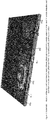
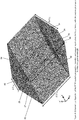
- FIG 3 this figure provides a schematic illustration of the configuration, and the relative dimensions, of one embodiment of the presently-proposed antenna.
- this is the configuration of an antenna which is thought to be capable of producing a radiation pattern (the shape/configuration/energy density distribution of) which in turn allows the RFID reader (of which the antenna forms part) to achieve the required read zone discussed in detail above, including with reference to Figure 1 and Figure 2 .
- the radiation pattern produced by the an antenna in Figure 3 is such that the antenna focusses/directs enough energy/power into the correct regions of space around (relative to) the antenna that the antenna (and its associated RFID reader electronics) are able to communicate with any plate tag that comes within the required read zone, such as the read zone described with reference to Figure 1 and Figure 2 .
- Figure 9 and Figure 10 contain schematic illustrations of the configuration of the proposed surrounding and supporting structure that an (embodiment of an) RFID reader may provide for the proposed antenna in Figure 3 .
- the origin of (or point of intersection between) the X, Y and Z axes is actually located, essentially, at the base of the antenna's feed pin 30, where the feed pin 30 connects to the ground plane 10.
- the antenna in the embodiment schematically illustrated in Figure 3 is a novel and highly advantageous design suitable for use in a low profile RFID reader antenna used in RFID communication in the UHF band. And it is to be stressed that the antenna in Figure 3 has a low profile . In other words, when the antenna (or the RFID reader containing the antenna) is placed/installed on the road or ground surface, the whole of the antenna (and likewise the associated RFID structure) remains low to the ground and does not project or "stick up" high above the ground.
- the antenna in the embodiment schematically illustrated in Figure 3 is able (it is thought) to achieve these things, and in relation to the requirement for the antenna to have a low profile, the overall height of the antenna in Figure 3 (and of the RFID reader as shown in Figure 9 ) is no more than about 25 mm.
- This maximum height (about 25 mm) is the same as the height of a typical cat-eye ("cat-eye” is the general name usually used to refer to the kind of raised, but low profile, retro-reflective road marker commonly used on public roads).
- Cat-eye is the general name usually used to refer to the kind of raised, but low profile, retro-reflective road marker commonly used on public roads.
- Limiting the height of the antenna, and the associated RFID reader, to no more than about 25 mm should help to ensure that vehicles may roll easily over the reader, without damage to the reader or the vehicle.
- the angle of attack (i.e. the angle of slope of the sides) on the sides of the RFID reader structure should be low (preferably no steeper than 45°) - this is mainly to reduce humans tripping over the unit.
- the antenna in Figure 3 has a structure comprising a ground portion 10 and a radiating component 20.
- the radiating component has a first side 22, and a second side 24 that is spaced apart from the first side 22.
- the first side 22 has a ground edge portion 23 which is in contact with the ground portion 10, and the first side 22 extends, from its ground edge portion 23, away (upward) from a surface (i.e. the surface of the ground portion 10) on one side (the upper side) of the ground portion 10.
- the second side 24 also has a ground edge portion 25 which is in contact with the ground portion 10, and the second side 24 also extends, from its ground edge portion 25, away (upward) from (in this case) the single/same surface on the upper side of the ground portion 10.
- the radiating component also has a joining portion 26 which is spaced apart from the ground portion 10 on said one side (the upper side) of the ground portion 10, and the joining portion 26 extends between the first side 22 and the second side 24, such that there is a region of space 29 defined between the first side 22 and the second side 24 and between the joining portion 26 and the ground portion 10.
- both the first side 22 and the second side 24 have a slot therein. These slots are labelled 27 and 28 respectively.
- the antenna's ground portion 10 is substantially flat/planar and rectangular, such that it might be referred to as a (rectangular) ground plane 10.
- the radiating component 20 might also be referred to as a top radiator.
- the antenna in the embodiment in Figure 3 has a flat ground plane 10 and box shaped top radiator 20.
- the two slots 27 and 28 in the respective sides of the top radiator 20 extend along for almost the entire length of the top radiator 20 on either side. And because the top radiator 20 extends substantially across the entire width of the ground plane 10 (and hence the entire width of the antenna), accordingly the respective slots 27 and 28 also extend across almost the entire width of the antenna. It is anticipated that the top radiator 20 will often be soldered to the ground plane 10.
- the two ends of the box shaped top radiator 20 are open - i.e. what would otherwise be the "faces" of the box shape that lie along the long edges of the antenna are missing/absent (or at least there are no conductive or radiative antenna elements located in or across or covering either of these ends of the open box shaped cavity within the radiator 20).
- the radiator 20 is fed from the ground plane 10 at the centre position with the help of a feeding pin 30 whose length is essentially the height of the antenna.
- the feed pin 30 is oriented perpendicularly to the ground plane 10 and it extends between and connects the ground plane 10 and the underside of the joining portion 26 of the radiator 20 half way along the length of the radiator 20 and half way between the first side 22 and the second side 24.
- the antenna is vertically polarized is important because the antenna needs to be able to communicate with the RFID tags on vehicle license plates, and it is thought (or expected) that the RFID tags on vehicle license plates will also be vertically polarised (i.e. they will produce vertically polarised radiation). This is due to the kinds of antenna likely to be used by the RFID tags on vehicle license plates (such as patch antennas, although a range of other types of antennas may be used by the RFID tags on vehicle license plates).
- the beam shape of the RFID tags on vehicle license plates will also (it is thought) point (or the direction of max gain of the radiation pattern of the antenna of the RFID tag on vehicle plates will point) directly away from the vehicle (or perpendicular to the plane of the license plate).
- the antenna emits energy in the form of electromagnetic waves that are vertically polarised is thought to be advantageous because electromagnetic waves which are vertically polarised propagate better when radiated from a ground plane than electromagnetic waves that are horizontally polarised.
- the slots 27 and 28 in the sides of the radiator 20 are both around 0.5 ⁇ 0 in length, where ⁇ 0 denotes the free space wavelength of the centre frequency used by the antenna.
- the total width of the antenna is slightly greater than this, at around 0.55 ⁇ 0 .
- the width of the antenna may still be increased further, if required, without significantly changing the antenna performance.
- the height of the top radiator 20 - i.e. the vertical distance between the ground plane 10 and the joining portion 26 (ignoring the thickness of the material used particularly in the radiator 20 which is very thin and therefore negligible) - is around 0.06 ⁇ 0 .
- the width of the top radiator 20 (i.e. its dimension in the antenna's overall lengthwise direction) is about 0.2 ⁇ 0 , which means that the slots 27 and 28 are both 0.1 ⁇ 0 away from the feeding pin 30 in the antenna's lengthwise direction. It is thought that this distance may help the antenna to effectively resonate and also provide high impedance matching.
- the ground plane 10, and hence the antenna overall, has a length of about ⁇ 0 , although this can be shortened through optimization.
- each of the slots is essentially (i.e. they both operate as) a half-wave radiator, with both of them being excited by a single feeding (the single feed pin 30).
- both slots operate as (or similar to) a half wave radiator
- the colour distributions in Figure 4 only indicate the magnitude of the magnetic filed strength in each slot.
- the relative polarity is represented in Figure 4 by the dashed line superimposed over slot 27, and as can be seen, the shape of this dashed line corresponds to the shape of half a sinusoidal waveform - so half the wavelength of the signal - thus indicating that the slot 27 operates as a half wave radiator, and it is the same for slot 28.
- this radiator box which is created by the overall configuration of the top radiator 20, this radiator box (i.e. the top radiator 20) functions (at least somewhat) in the manor of a (electromagnetic) cavity resonator. What a cavity resonator is, and generally how they work/operate, is well understood in the field of electronics and antenna design. However, for the purposes of brief explanation here, it is stated in Wikipedia ( https://en.wikipedia.org/wiki/Resonator ) that
- the top radiator 20 in the antenna presently being considered here is not actually (or merely) a conventional/pure cavity resonator.
- the top radiator 20 is open ended at either end (see above), not fully enclosed like conventional cavity resonators, and the top radiator 20 also incorporates other openings in the form of the slots 27 and 28 along its respective long sides - these particularly have a significant impact on the overall radiative properties of the top radiator 20 vis-à-vis a conventional cavity resonator.
- the radiator box i.e. the top radiator 20 in the present antenna functions in at least something like the manor of a cavity resonator.
- the top radiator 20 (and indeed the antenna overall) must have a low profile (i.e. a low physical height). This is significant because it is actually very difficult to design a cavity resonator (or an antenna incorporating a cavity resonator) which has a low profile (low physical height) and which also provides good impedance matching.
- impedance matching is also well understood in the fields of antenna design and electronics generally.
- impedance matching is essentially about making two impedances, like (a) the impedance of a transmitting antenna and (b) the output impedance of the signal transmitter (or its amplifier) that supplies the signal (as an electrical current) to the transmitting antenna, match.
- the reason why matching these impedances is important is because if the impedances do not match, none of (or very little of) the power generated by the signal transmitter (or its amplifier) will be delivered to the antenna, and therefore no energy (or very little energy) will be transmitted by the antenna.
- the impedance of the antenna is much smaller than the output impedance of the transmitter, little or no energy will be transmitted by the antenna, but equally (and recalling that we are talking about low frequencies), if the impedance of the antenna is much larger than the output impedance of the transmitter, again, little or no energy will be transmitted by the antenna.
- impedance matching does not simply involve setting the impedance of the antenna to be equal to the output impedance of the transmitter. Rather, at low frequencies, the antenna impedance and the transmitter output impedance will generally be matched if one is set as (or about) the complex conjugate of the other.
- the basic premise remains the same, namely that the purpose of impedance matching is (in terms of the example above) to ensure that the output impedance of the transmitter and the antenna impedance are set (or so that one is set relative to the other) in a manner that maximises the power delivered to, and radiated by, the antenna.
- VSWR voltage standing wave ratio
- a related quantity is the above mentioned quantity, return loss.
- Return loss is a measure (in dB) of the ratio of the power in the incident signal to that in the reflected signal, and as defined it is always positive.
- the matching between a transmitter and its antenna achieves a 10 dB return loss, this means that 1/10 (or 10%) of the incident power is reflected. Note: the higher the return loss, the less power is actually lost.
- Mismatch loss is a measure of how much the transmitted power is attenuated due to the reflection.
- an antenna with a VSWR of 2 would have a reflection coefficient of 0.333, a mismatch loss of 0.51 dB, and a return loss of 9.54 dB (meaning approximately 11% of the transmitter power is reflected back).
- VSWR this is a real number that is always greater than one.
- a VSWR of 1 indicates no mismatch loss (and also no return loss, meaning the antenna is perfectly matched to the transmitter). Higher VSWR values indicate greater mismatch loss and lower return loss.
- a VSWR of 3.0 indicates about 75% of the power is delivered to the antenna (i.e. 1.25 dB mismatch loss, 6.0 dB return loss, and about 25% of the transmitted power is lost).
- a VSWR of 5.0 indicates about 44% of the power is lost (i.e. 2.55 dB mismatch loss and a 3.5 dB return loss.
- typical antenna matching achieves a return loss of approximately 10 dB (equivalent to a VSWR of approximately 2).
- a VSWR better than 1.25 is thought to be desired for the signal frequency band (i.e. the antenna's operational signal frequency band) of interest.
- the general antenna configuration described above i.e. with the particular dimensions described above can be applied for use in, for example, the 866 MHz and 900 MHz RFID bands.
- Figure 5 and Figure 6 illustrate the radiation pattern produced by the antenna in Figure 3 in 3D, and in the Y-Z-plane, respectively, at a signal frequency of 920 MHz.
- Figure 7 and Figure 8 also illustrate the radiation pattern produced by the antenna in Figure 3 in 3D, and in the Y-Z-plane, respectively, at the same frequency. The reason the radiation pattern depicted in Figure 7 and Figure 8 differs from that in Figure 5 and Figure 6 will be explained below.
- Figure 5 depicts the basic shape of the antenna's radiation pattern, and also the orientation of the radiation pattern relative to the antenna and its various components; however the actual size with which the radiation pattern is depicted relative to the antenna (i.e. relative to the antenna's base plate 10 and top radiator 20) in these Figures is not representative of the true size/extent of the radiation pattern relative to the size of the antenna.
- Figure 5 and Figure 6 both illustrate an "ideal" radiation pattern of the antenna in Figure 3 (i.e. the radiation pattern of the antenna described above based on a number of "idealised” assumptions).
- Figure 5 and Figure 6 illustrate the radiation pattern of the antenna in Figure 3 assuming an infinite, ideal road condition and a perfectly reflective ground plane.
- the antenna has (or can be modelled to have) a bi-directional radiation pattern comprising two opposing, quite round and smooth "lobes" 57 and 58, each with a peak gain of 5.3 dBi at 40° elevation above the ground plane (i.e.
- the difference or change in the antenna's reflection coefficient in the more realistic antenna (and it's radiation pattern representations) in Figure 7 and Figure 8 is actually quite small and insignificant.
- moving from the idealised to the more realistic antenna there are quite notable changes in the shape and configuration of the antenna's radiation pattern. Note that, unlike the lobes 57 and 58 of the radiation pattern of the idealised antenna, which each have a quite smooth/clean and rounded shape, the respective lobes or "sides" 77 and 78 of the radiation pattern of the more realistic antenna both have a less even and more lumpy shape.
- this is not thought to be a major problem because vehicles will rarely (if ever) approach the antenna from directly to the side of the antenna (i.e.
- the antenna will be oriented with its long axis (i.e. the long sides of the ground plane) parallel to the direction in which vehicles will travel as they approach or passed by/over the antenna, and as mentioned above, it is also the case in these kinds of applications that the vehicles will approach the antenna in a direction, and within a range of lateral locations relative to the antenna, that is known/predictable with fairly high confidence.
- Figure 9 and Figure 10 both illustrate schematically the configuration of an RFID reader, wherein the antenna incorporated in the RFID reader and which the RFID reader uses for RFID communication with RFID tags mounted on vehicle license plates, is the particular embodiment of the antenna described above, including with reference to Figure 3 .
- Figure 9 and Figure 10 both show, in particular (in addition to the antenna itself) the surrounding and supporting structure which the RFID reader has/provides for surrounding and supporting the antenna.
- a small box 73 is visible on one side of the antenna's top radiator.
- This small box 73 represents an electronic component, or a housing containing electronic components (possibly light-emitting electronic components), or it might alternatively be considered to represent an additional antenna used for wireless (e.g. Bluetooth) communication between the RFID reader and some other computer or mobile device, etc.
- the component 73 whatever it is, may be positioned in the RFID reader at the location shown in Figure 10 . There could also be a similar, or some other, electronic component located at essentially the same location but on the other side of the antenna in the RFID reader.
- the component 73 is not shown in Figure 9 ; and nor is any other electronic component that might be mounted in the same location but on the other side of the antenna. However, again, this is not intended to suggest that the antenna in the RFID reader in Figure 9 does not include this/these electronic component(s). It does; it's just that this is not depicted in Figure 9 .
- Figure 9 Another difference between Figure 9 and Figure 10 is that in Figure 9 the dimensions of the antenna, and also of portions of the RFID reader's supporting structure, are given in terms of (i.e. as a function of) signal wavelength ( ⁇ 0 ), whereas in Figure 10 dimensions are given in millimetres. Note that the particular dimensions given in Figure 10 are applicable to an antenna/RFID reader that operates at a frequency of about 900-940 MHz.
- the antenna's ground plane 10 becomes positioned on the upper surface of the road such that the antenna's top radiator 20 is on the opposite side of the of the ground plane 10 from the road surface.
- the underside of the antenna's ground plane component/portion 10 sits face down on the road surface, or possibly face down on one or more thin intermediate layers, e.g. an adhesive layer for securing the RFID reader to the road and/or maybe some other thin intermediate shielding or other layer(s), and the antenna's top radiator 20 sits on top of (and projects upward from) the upper side of the antenna's ground plane 10.
- Figure 9 and Figure 10 also show that the RFID reader incorporates a number of rigid portions with sloped upper surfaces.
- included among the RFID reader's rigid portions are a sloped rigid portion on either side of the RFID reader, each along a respective long side/edge of the antenna - one of these is marked 80 and the other 90 - and in this particular embodiment both of the said rigid portions 80 and 90 might themselves be said to include three sections.
- the three sections thereof include a first section 82, a second section 84 and a middle section 86 which is interposed between the first section 82 and second section 84.
- the three sections thereof include a first section 92, a second section 94 and a middle section 96 interposed in the first section 92 and second section 94.
- each rigid portion 80 and 90 whilst these are described as each including three sections, this is not intended to imply that in each (or either) case the three sections are necessarily independent or separate or separately formed from the other sections. Of course, it is possible that there could be in some embodiments where they are. However, it is thought that more often the respective sections of each rigid portion 80 and 90 will be integrally formed with one another (i.e. together, as one part), and in fact the rigid portions 80 and 90 may (and often will) themselves be integrally formed together with others of the RFID reader's rigid portions - see below.
- each of the rigid portions 80 and 90 is described here as including three sections is simply because, due to the respective shapes of the rigid portions 80 and 90 in this embodiment, this is simply the most logical and easiest way to describe them.
- the overall shape of a rigid portion equivalent to 80 or 90 (or both) is smooth and therefore lacking any edges that notionally divide it into differently-shaped sections.
- the specific shape of the sections 82, 84, 86 and 92, 94, 96 in Figure 9 and Figure 10 is not crucial (and similar functionality may be achieved using somewhat different shape(s)).
- the reason the respective rigid portions 80 and 90 are described this way is, basically, for convenience in describing their particular configuration, and the shape and location of their various sections, in the particular embodiment depicted in Figure 9 and Figure 10 .
- each of the rigid portions 80 and 90, and each of the respective sections thereof has an outer perimeter edge. In all cases, this outer perimeter edge lies in the plane of the antenna's ground plane 10. Thus, when the RFID reader is installed, the respective outer perimeter edges of the rigid portions 80 and 90 (and their various sections) sit directly on the surface of the road (just like the antenna's ground plane 10). In many embodiments, most (and perhaps all) of the rigid portions in the RFID reader will be substantially solid. In other embodiments though, one or some of the rigid portions may be somewhat hollow (i.e. having a space or opening inside, for example to house electronic components like the electronic component 73, or the like). However, in all cases, all of the RFID reader's rigid portions will have an unbroken upper surface. (Therefore, even if there are some rigid portions of the RFID reader that have an opening or hollow inside, the said hollow or opening inside that/those rigid portion(s) will be covered up by the rigid portion(s) unbroken upper surface.)
- the upper surface slopes upward from the outer perimeter edge toward the antenna's top radiator 20. More specifically, for the respective middle sections 86 and 96 on either side of the antenna, the outer perimeter edge of each of these lies on the road parallel to the outer edge of the antenna. Therefore, moving from the outside in, the upper surface of each of the respective middle sections 86 and 96 begins at its outer perimeter edge (which lies on the road) and slopes upward such that the inner side thereof meets the antenna's top radiator at the top outer edge of radiator 20. For the respective first sections 82 and 92, and second sections 84 and 94, the outer perimeter edges of these all lie (in the plane of the ground plane 10) at an angle to the side edge of the antenna.
- the outer perimeter edges of the first and second sections all lie directly on the surface of the road, but each of these outer perimeter edges extends from (at one end) one of the corners of the antenna's ground plane 10 to connect (at the other end thereof) with one of the ends of the outer perimeter edge of the relevant middle section 86 or 96.
- the "planform" or “footprint” shape of each respective first section 82 and 92 and second section 84 and 94 is a right angled triangular, with the outer perimeter edge of each said triangle forming the hypotenuse.
- the upper surface thereof slopes upward from the outer perimeter edge (the hypotenuse of the triangular footprint) towards the antenna's top radiator 20.
- the upper surface also forms a right angled triangle, again with the outer perimeter edge (which is on the ground/road) forming the hypotenuse, but with the right angled corner this time (for each of them) meeting at a respective top corner of the antenna's top radiator 20.
- the upper surfaces of the respective three sections that make up each of these all slope upward from ground/road level and they all meet at their respective highest points at the level of (and in contact with) the top of the antenna's top radiator 20.
- the upper surfaces of all of the sections on both of the rigid portions 80 and 90 are planar. Therefore, they do not curve or change slope (i.e. the angle of inclination remains fixed) as they extend up from ground level to meet at the level of the antenna's top radiator.
- the RFID reader in Figure 9 and Figure 10 has as a rigid portion 80 on one side of the antenna and also a rigid portion 90 on the opposite side.
- the rigid portion 90 is essentially a mirror image of the rigid portion 80, unless perhaps one contains hollows or openings inside it which the other does not, or which are different to the other, etc.
- these rigid portions 80 and 90 are not the only rigid portions in this embodiment of the RFID reader.
- the RFID reader also incorporates two further rigid portions, namely rigid portions 102 and 104 - see the dashed lines in Figure 10 . (Note that the dashed lines in Figure 10 are not edges or markings that are actually visible on the RFID reader in reality.
- the dashed lines are included on Figure 10 simply to assist in visualising the shape and location of the rigid portions 102 and 104.
- the outer perimeter edge of the rigid portion 102 runs along (i.e. it meets or sits directly on top of) the end-edge of the antenna's ground plane 10 at one end of the ground plane, and it extends across the full width of the ground plane 10.
- the outer perimeter edge of the rigid portion 104 runs along (i.e. it meets or sits directly on top of) the end-edge of the antenna's ground plane 10 at the other end of the ground plane, and it too extends across the full width of the ground plane 10.
- the rigid portions 102 and 104 are both solid, or perhaps one or both of them may have a hollow or opening inside, but nevertheless both have an unbroken upper surface, and the upper surfaces of the respective rigid portions 102 and 104 slope from their respective outer edges (both on or just above a respective end-edge of the ground plane 10) inward and upward such that the inner sides/edges of the respective rigid portions 102 and 104 meet the long side edges at the top of the antenna's top radiator 20.
- the inner side/edge of the rigid portion 102 meets the top radiator at the junction between the sidewall 22 and the joining portion 26 of the top radiator 20.
- the inner side/edge of the rigid portion 104 meets top radiator at the junction between the sidewall 24 and the joining portion 26 of the top radiator 20.
- the rigid portions 102 and 104 all portions/areas of the antenna's ground plane 10 which are located forward and aft of the top radiator 20 in the antenna's longitudinal/lengthwise direction are beneath and therefore covered by the rigid portions 102 and 104. These portions or areas of the ground plane 10 are therefore be protected (e.g. from physical damage or exposure to the elements, etc) by the rigid portion 102 and 104. Also, the rigid portions 80 and 90 also protect the sides of the antenna. Furthermore, as mentioned above, in many embodiments, the rigid portions 80 and 90 and also the rigid portions 102 and 104 may be intimately formed together as one piece.
- the antenna's ground plane 10 the antenna's top radiator 20, and in the other components of the antenna, plus also any electronic components that are included in or form part of the RFID reader, are (in this embodiment anyway) effectively embedded beneath and within the integral combined rigid portions, which survey protective and structurally supported function, as discussed below.
- the rigid portions 102 and 104 effectively cover the portions of the ground plane 10 that are forward and aft of the top radiator 20, thereby protecting these portions of the ground plane 10 from e.g. physical damage, damage through exposure to the elements, except. It was also mentioned in passing that the rigid portions 80 and 90 provide similar protection for the antenna from the sides.
- rigid portions of the RFID reader are actually also responsible for providing the physical supporting structure for the RFID reader's antenna, as well as any other electronic components and the like that may be contained in or form part of the RFID reader. The way in which the rigid portions provide the RFID reader's physical structure can be understood quite simply. Consider the components of the antenna.
- the components of the antenna will often be made from thin metal, perhaps only a few millimetres or possibly even less than a millimetre in thickness.
- the top radiator 20 is also elevated relative to (i.e. it is located vertically above) the antenna's ground plane 10 when the reader is installed on the road.
- thin metal such as this, especially if elevated/upstanding and unsupported in "free space", would be very flexibly and flimsy. It should also be recognised that, by virtue of its location on a road surface, the RFID reader may often be directly run over by vehicles.
- the RFID reader (including its antenna structure) to be able to withstand such forces and impacts repeatedly and over a long period of time without damage or affect on the reader's/antenna's functioning or performance. It is therefore also clear there needs to be something to prevent any otherwise thin/flimsy pieces of metal that make up or are comprised in the RFID reader or its antenna (in particular the radiating component) from simply being crushed/flattened and completely destroyed by such vehicle impacts. It is this function that the rigid portions provide.
- the components of the antenna are effectively embedded beneath and within the integrally combined rigid portions, and as a result, not only are the components of the antenna protected from damage when vehicles drive over the RFID reader by the rigid portions which are themselves able to withstand this (meaning that the antenna components which are safely housed within are also protected from damage), but the components of the antenna are also themselves supported within the rigid portions (i.e. held in position and prevented from deforming or separating or warping or the like).
- each rigid portion should be quite gentle (i.e. not steep), and it will now be recognised that the reason why this important is to allow vehicle wheels/tires to easily roll over the RFID reader (i.e. directly over the top of the whole RFID reader, or over a portion of the RFID reader), without causing a large or dangerous pump or jolt to the vehicle.
- ensuring that the angles of inclination of the respective rigid portions (and the various sections thereof) are gentle may also help to at least a somewhat reduce the risk or likelihood of a person tripping or stumbling or injuring themselves should they accidentally kick or trip on the RFID reader.
- the slope of the upper surface on any rigid portion of the RFID reader should preferably be no steeper than 45°.
- the maximum thickness of the RFID reader in a direction perpendicular to the road i.e. the maximum height of the RFID reader
- the maximum thickness (about 25 mm) is considered to be acceptable, and it is also thought to be also compliant from a standards/regulatory point of view, as this is the same height as (or perhaps it may even be slightly less than) the height of many conventional "cat eyes" and other retroreflective devices commonly used on public roads.
- the embodiment of the RFID reader shown in Figure 10 for example, achieves this. Indeed the height of that RFID reader at its highest point (which is in the centre at the top of the top radiator 20) is only 20 mm.
- the material from the rigid portions of the RFID reader in Figure 9 and Figure 10 are made (and it will be recalled that all of the rigid portions in this RFID reader may, in fact, be integrated formed together) should be physically strong/tough and durable (i.e. so as to be able to withstand repeated impact loading e.g. when vehicles drive over the top, and so as to thereby provide the structural support for parts of the antenna inside, as well as able to withstand prolonged exposure to the sun and other elements, significant temperature fluctuations, etc).
- the material from the rigid portions are made should also have dielectric properties which do not substantially interfere with the impedance matching and/or radiation performance/characteristics of the antenna, or it may be that the dielectric properties of the material can be used (e.g.
- the material from the rigid portions are formed may also be optically transparent, or at least optically translucent.
- Suitable material from which the rigid portions of the RFID reader may be made include various types of polycarbonate, polyethersulfane, or like materials. Examples of specific materials that may be suitable include the materials produced by the Rochling group of companies and sold under the names/trade marks SUSTARIN C, SUSTANAT PC and SUSTASON PES.
- rigid portions may be made from an optically transparent (or optically translucent) material
- an optically transparent (or optically translucent) material include: so as to allow for light to be emitted from light emitting components (see below), and to allow for solar panels, which may be mounted on or incorporated into the structure of the RFID reader (and which may be partially or wholly covered or inside the rigid portion material), to receive light/solar radiation from which energy is thereby generated.
- the RFID reader may include one or more light emitting components e.g. such as LEDs, lights or the like (illustrated). Such light emitting components may be located or housed in one or both of the open ends of the top radiator 20 - such lights may be most visible when the RFID reader is observed (when the lights are illuminated) from the side.
- the RFID reader could includes one or more light-emitting components located within the material of one or both of the rigid portions 80 and 90, which would thereby replace that/those light emitting components outside of the antenna, possibly making them more visible from in front and behind the antenna in the lengthwise/longitudinal direction as well as from the side of the RFID reader.
- At least some, and possibly most, of the RFID reader's electronics and circuitry may be located within the region of space inside the top radiator 20 (i.e. beneath the radiator's joining portion 26 and between its sidewalls 22 and 24). Note that, at least usually, whilst the regions immediately above the ground plane 10 and also immediately to the sides of the antenna will be filled with the material that forms the rigid portions 80, 90, 102, 104 (see above), nevertheless the region of space inside the top radiator may remain unfilled by this material.
- the antenna's top radiator 20, and possibly also the ground portion 10 is made from a material (typically metal) having a suitably high electrical conductivity.
- the material from which at least the top radiator 20 (and preferably also the ground plane 10) is made should also be thermally conductive, so that at least the top radiator 20 can help (as a secondary function) to dissipate heat generated by any RFID reader electronics and circuitry located within the cavity inside the top radiator 20.
- the RFID reader may be powered in any suitable way. Options include that the RFID reader is powered by induction loop or by power-supply wires/cables connected to the RFID reader (connected once it has been installed). Alternatively, or in addition thereto, the RFID reader may incorporates one or more solar (photovoltaic) cells. It is possible that, in some embedment's, the solar cells may be operable to produce and supply to the RFID reader enough electrical energy to partly or even fully power the RFID reader (or certain parts or components of the rear, or certain of its functionalities). In the embodiment depicted in Figure 10 , solar cells could be located e.g. on top of the joining portion 26 of the top radiator 20.
- the solar cells should not significantly interfere with the antenna's radiative properties, and this may also be a convenient location given the ease with which cables or connectors could then be made to carry electricity generated using the PV cells to the RFID reader's internal circuitry (which is located, at least mostly, within the cavity inside the top radiator 20 and therefore immediately beneath the PV cells).
Landscapes
- Engineering & Computer Science (AREA)
- Physics & Mathematics (AREA)
- Toxicology (AREA)
- Health & Medical Sciences (AREA)
- Electromagnetism (AREA)
- General Health & Medical Sciences (AREA)
- Computer Networks & Wireless Communication (AREA)
- Artificial Intelligence (AREA)
- Computer Vision & Pattern Recognition (AREA)
- General Physics & Mathematics (AREA)
- Theoretical Computer Science (AREA)
- Details Of Aerials (AREA)
- Waveguide Aerials (AREA)
- Support Of Aerials (AREA)
Claims (14)
- Antenne für eine Kommunikationsvorrichtung, wobei die Antenne eine Struktur aufweist, die Folgendes umfasst:▪ einen im Wesentlichen planaren, elektrisch leitenden Bodenabschnitt (10) und▪ eine elektrisch leitende Strahlungskomponente (20),∘ wobei die Strahlungskomponente eine erste Seite (22) und eine zweite Seite (24), die von der ersten Seite (22) beabstandet ist, aufweist, unddie erste Seite einen Bodenrandabschnitt (23) aufweist, der in Kontakt mit dem Bodenabschnitt (10) ist, und sich die erste Seite (22), von ihrem Bodenrandabschnitt (23), weg von einer Oberfläche auf einer Seite des Bodenabschnitts (10) erstreckt;die zweite Seite (24) auch einen Bodenrandabschnitt (25) aufweist, der in Kontakt mit dem Bodenabschnitt (10) ist, und sich die zweite Seite (24) auch, von ihrem Bodenrandabschnitt (25), weg von einer Oberfläche auf der einen Seite des Bodenabschnitts (10) erstreckt;wobei die erste Seite (22) und die zweite Seite (24) der Strahlungskomponente (20) beide im Wesentlichen planar und rechteckig sind und beide mit ihren Ebenen im Wesentlichen senkrecht zu der Ebene des Bodenabschnitts (10) ausgerichtet sind, und∘ die Strahlungskomponente (20) auch einen Verbindungsabschnitt (26) aufweist, der von dem Bodenabschnitt (10) auf der einen Seite des Bodenabschnitts (10) beabstandet ist, und sich der Verbindungsabschnitt (26) zwischen der ersten Seite (22) und der zweiten Seite (24) erstreckt, sodass es einen Raumbereich (29) gibt, der zwischen der ersten Seite (22) und der zweiten Seite (24) und zwischen dem Verbindungsabschnitt (26) und dem Bodenabschnitt (10) definiert ist, wobei der Raumbereich (29) an beiden Enden offen ist; undo die erste Seite (22) und die zweite Seite (24) jeweils einen Schlitz (27, 28) darin aufweisen, wobei sich die Schlitze (27, 28) in den Seiten (22, 24) der Strahlungskomponente (20) annähernd parallel zu den Bodenrandabschnitten (23, 25) der Seiten erstrecken, und/oder wobei sich die Schlitze (27, 28) in den Seiten (22, 24) der Strahlungskomponente (20) fast über die gesamte Länge des Bodenrandabschnitts (23, 25) der Seiten erstrecken,
wobei die Antenne von dem Bodenabschnitt (10) mit einem Einspeisungsstift (30) gespeist wird, der sich zwischen dem Bodenabschnitt (10) und der Unterseite des Verbindungsabschnitts (26) der Strahlungskomponente erstreckt und diese verbindet, und wobei der Einspeisungsstift (30) senkrecht zu dem Bodenabschnitt (10) ausgerichtet ist und den Bodenabschnitt (10) mit der Unterseite des Verbindungsabschnitts (26) auf halbem Weg entlang der Länge des Verbindungsabschnitts (26) und auf halbem Wege zwischen der ersten Seite (22) und der zweiten Seite (24) der Strahlungskomponente (20) verbindet, und wobei▪ sowohl auf der ersten Seite (22) als auch auf der zweiten Seite (24) der Strahlungskomponente (20):∘ der Bodenrandabschnitt (23, 25), der mit dem Bodenabschnitt (10) in Kontakt ist, eine der längeren Ränder der rechteckigen Form der Seite bildet;∘ es einen distalen Randabschnitt gegenüber dem Bodenrandabschnitt (23, 25) gibt, der den anderen der längeren Ränder der rechteckigen Form der Seite bildet, und▪ der Verbindungsabschnitt (26) der Strahlungskomponente (20) im Wesentlichen ungebrochen, planar und rechteckig ist und sich zwischen den distalen Randabschnitten der ersten Seite (22) und der zweiten Seite (24) entlang der gesamten Länge der Strahlungskomponente (20) erstreckt. - Antenne gemäß Anspruch 1, wobei der Raumbereich (29), der zwischen der ersten Seite (22) und der zweiten Seite (24) der Strahlungskomponente (20) und zwischen dem Verbindungsabschnitt (26) der Strahlungskomponente (20) und dem Bodenabschnitt (10) definiert ist, im Wesentlichen als rechteckiges Prisma oder als Kastenform geformt ist.
- Antenne gemäß einem der vorherigen Ansprüche, wobei der Bodenabschnitt (10) als Bodenebene (10) konfiguriert ist und die Bodenebene (10) rechteckig mit einer Längenabmessung und einer Breitenabmessung ist, wobei die Längenabmessung größer ist als die Breitenabmessung, und die Strahlungskomponente (20) eine Länge aufweist, die sich im Wesentlichen über die Breite der Bodenebene (10) erstreckt.
- Antenne gemäß Anspruch 3, wobei die Länge der Bodenebene (10) etwa λ0 ist, wobei λ0 die Freiraumwellenlänge der Mittenfrequenz des Betriebssignals der Antenne ist, und eines oder mehrere von Folgenden gelten:▪ die Breite der Bodenebene (10) ist etwa 0,55 > λ0 oder mehr;▪ die Länge der Bodenebene (10) kann auch durch oder als Teil einer Antennenabstimmung auf weniger als λ0 reduziert werden;▪ die Länge des Schlitzes (27, 28) in jeder von der ersten Seite (22) und der zweiten Seite (24) ist etwa 0,5 λ0;▪ der Verbindungsabschnitt (26) der Strahlungskomponente (20) von der Bodenebene (10) ist um etwa 0,06 λ0 beabstandet; und▪ die erste Seite (22) und die zweite Seite (24) der Strahlungskomponente (20) sind um etwa 0,2 λ0 beabstandet.
- Antenne gemäß einem der vorherigen Ansprüche, wobei:▪ der Bodenabschnitt (10) der Antenne und die Strahlungskomponente (20) beide aus einem Metall oder einem auf Metall basierenden Material gefertigt sind, und/oder▪ die Strahlungskomponente (20) der Antenne aus dünnen, elektrisch leitenden Drähten gefertigt ist, die angeordnet sind, sodass sie zusammen die Form der Strahlungskomponente (20) der Antenne definieren, und zwischen den Drähten offene Räume verbleiben, sodass die Strahlungskomponente (20) der Antenne (mindestens) im Wesentlichen optisch transparent ist.
- Antenne gemäß einem der vorherigen Ansprüche, wobei die Antenne konfiguriert ist, sodass das Strahlungsmuster der Antenne in der Azimut-Ebene (Z=0) im Wesentlichen bidirektional ist und die Form des Strahlungsmusters für jede der zwei Richtungen einen oder mehrere runde oder bauchige "Keulen"-förmige Abschnitte (57, 58) aufweist, wovon jeder generell in einer Längsrichtung der Antenne weg von der Strahlungskomponente (20) zeigt, und wobei mindestens der Großteil von jeder "Keulen"-Form (57, 58) in einem Winkel (ϕ, θ) zwischen 0° und 90° Höhe über dem Bodenabschnitt (10) angeordnet ist.
- Antenne gemäß Anspruch 6, wobei die Antenne konfiguriert ist, sodass innerhalb einer Ebene, die senkrecht zu dem Bodenabschnitt (10) der Antenne ist, aber mit der Längsmittelachse der Bodenebene (10) ausgerichtet ist, die 3 dB-Strahlbreite des Strahlungsmusters der Antenne innerhalb des Winkelbereichs (ϕ, θ) zwischen etwa 30° und etwa 65° Höhe über dem Bodenabschnitt (10) enthalten ist.
- RFID-Lesegerät, das auf einer Straßen- oder Erd- oder Bodenfläche installiert werden kann, wobei eine in das RFID-Lesegerät integrierte Antenne, die von dem RFID-Lesegerät für die RFID-Kommunikation verwendet wird, eine Antenne gemäß einem der vorherigen Ansprüche ist.
- RFID-Lesegerät gemäß Anspruch 8, das ferner einen oder mehrere starre Abschnitte (80/90/102/104) mit (einer) geneigten oberen Fläche(n) integriert, wobei:▪ die Neigung der oberen Fläche von jedem starren Abschnitt (80/90/102/104) auf der Höhe des Bodenabschnitts (10) der Antenne beginnt;▪ jeder starre Abschnitt generell nach oben in Richtung der Strahlungskomponente (20) der Antenne geneigt ist, und▪ die schräge obere Fläche von jedem starren Abschnitt etwa auf der Höhe des Verbindungsabschnitts (26) der Strahlungskomponente (20) der Antenne auf die Strahlungskomponente (20) der Antenne trifft,
- RFID-Lesegerät gemäß Anspruch 9, wobei:▪ es einen starren Abschnitt (102, 104) gibt, der an jedem von den Endrändern des Bodenabschnitts (10) der Antenne beginnt, und die starren Abschnitte (102, 104) sich von den jeweiligen Endrändern nach oben neigen, um auf der Höhe des Verbindungsabschnitts (26) der Strahlungskomponente auf die Strahlungskomponente (20) der Antenne zu treffen, sodass Abschnitte oder Bereiche des Bodenabschnitts (10) der Antenne auf beiden Seiten der Strahlungskomponente (20) der Antenne, die sich zwischen dem Strahlungskomponente (20) der Antenne und den jeweiligen Endrändern des Bodenabschnitts (10) der Antenne befinden, unterhalb der starren Abschnitte (102, 104) sind, und/oder▪ es mindestens einen starren Abschnitt (80, 90) gibt, der über die Seitenränder des Bodenabschnitts (10) der Antenne hinaus auf beiden Seiten des Bodenabschnitts (10) beginnt, und sich die starren Abschnitte (80, 90) von dort aus nach oben neigen, um auf der Höhe des Verbindungsabschnitts (26) der Strahlungskomponente auf die Strahlungskomponente (20) der Antenne zu treffen, und/oder▪ die Neigung der oberen Fläche an jedem starren Abschnitt des RFID-Lesegeräts nicht steiler als 45° ist.
- RFID-Lesegerät gemäß einem der Ansprüche 8 bis 10, wobei, falls oder wenn das RFID-Lesegerät auf der Straßen- oder Erd- oder Bodenfläche installiert ist, die maximale Stärke des RFID-Lesegeräts in einer Richtung senkrecht zu der Straße oder dem Boden oder der Bodenfläche nicht mehr als etwa 25 mm ist.
- RFID-Lesegerät gemäß einem der Ansprüche 8 bis 11, wobei das RFID-Lesegerät mehr als einen starren Abschnitt aufweist, und:▪ mindestens ein starrer Abschnitt zunächst getrennt von mindestens einem anderen starren Abschnitt gebildet ist und diese anschließend zusammen mit einem oder mehreren anderen starren Abschnitten, der Antenne und anderen Teilen oder Komponenten zusammengebracht oder zusammengebaut werden, wenn das RFID-Lesegerät gebildet/zusammengebaut wird, und/oder▪ das Material, aus dem mindestens einer der starren Abschnitte gebildet ist, physisch stark/zäh und haltbar ist, und/oder das Material dielektrische Eigenschaften aufweist, die die Impedanzanpassung und/oder die Strahlungsleistung/-merkmale der Antenne nicht wesentlich beeinträchtigen, oder die dielektrischen Eigenschaften des Materials verwendet werden können, um das Strahlungsmuster und/oder die Strahlungsleistung/-merkmale der Antenne auf kontrollierbare Weise zu verändern, und/oder▪ das Material, aus dem mindestens einer der starren Abschnitte gebildet ist, optisch transparent oder zumindest optisch lichtdurchlässig ist, wobei in diesem Fall optional der Raumbereich, der zwischen der ersten Seite (22) und der zweiten Seite (24) der Strahlungskomponente (20) der Antenne und zwischen dem Verbindungsabschnitt (26) der Strahlungskomponente (20) der Antenne und dem Bodenabschnitt (10) der Antenne definiert ist, an beiden Enden offen ist und das RFID-Lesegerät eine oder mehrere lichtemittierende Komponenten beinhaltet, die sich an einem oder beiden der Enden oder an anderer Stelle innerhalb des Materials eines oder mehrerer der starren Abschnitte befinden oder untergebracht sind, und/oder▪ das Material, aus dem mindestens einer der starren Teile gebildet ist, eine Art von Polycarbonat oder Polyethersulfan ist.
- RFID-Lesegerät gemäß einem der Ansprüche 8 bis 12, wobei mindestens ein Teil der Elektronik und der Schaltungen des RFID-Lesegeräts innerhalb des Raumbereichs angeordnet ist, der zwischen der ersten Seite (22) und der zweiten Seite (24) der Strahlungskomponente (20) der Antenne und zwischen dem Verbindungsabschnitt (26) der Strahlungskomponente (20) der Antenne und dem Bodenabschnitt (10) der Antenne definiert ist.
- RFID-Lesegerät gemäß einem der Ansprüche 8 bis 13, wobei:▪ das RFID-Lesegerät ferner für eine separate drahtlose Kommunikation mit einer oder mehreren anderen elektronischen Vorrichtungen konfiguriert ist,▪ das RFID-Lesegerät ferner eine sekundäre Antenne umfasst,▪ das RFID-Lesegerät konfiguriert ist, um die sekundäre Antenne zu verwenden, um die separate drahtlose Kommunikation mit anderen elektronischen Vorrichtungen zu ermöglichen, und/oder▪ das RFID-Lesegerät eine oder mehrere Solarzellen integriert, wobei die Solarzellen funktionsfähig ist/sind, um ausreichend elektrische Energie zu erzeugen und dem RFID-Lesegerät zuzuführen, um das RFID-Lesegerät teilweise oder vollständig mit Energie zu versorgen, und die eine oder mehreren Solarzellen optional oben auf dem Verbindungsabschnitt (26) der Strahlungskomponente (20) der (Haupt-)Antenne des RFID-Lesegeräts angeordnet sind, und ferner optional die Strahlungskomponente (20) der (Haupt-)Antenne des RFID-Lesegeräts aus dünnen, elektrisch leitenden Drähten gefertigt ist, die angeordnet sind, sodass sie zusammen die Form der Strahlungskomponente (20) der Antenne definieren, und zwischen den Drähten offene Räume verbleiben, sodass das Strahlungskomponente (20) der Antenne (mindestens) im Wesentlichen optisch transparent ist, und die Solarzellen auf der Höhe des Bodenabschnitts (10) der Antenne oder direkt darauf montiert sind oder diese bilden.
Applications Claiming Priority (1)
| Application Number | Priority Date | Filing Date | Title |
|---|---|---|---|
| AU2016905266A AU2016905266A0 (en) | 2016-12-20 | An Antenna |
Publications (2)
| Publication Number | Publication Date |
|---|---|
| EP3340376A1 EP3340376A1 (de) | 2018-06-27 |
| EP3340376B1 true EP3340376B1 (de) | 2021-11-03 |
Family
ID=60673526
Family Applications (1)
| Application Number | Title | Priority Date | Filing Date |
|---|---|---|---|
| EP17207142.5A Active EP3340376B1 (de) | 2016-12-20 | 2017-12-13 | Antenne |
Country Status (4)
| Country | Link |
|---|---|
| US (1) | US10402601B2 (de) |
| EP (1) | EP3340376B1 (de) |
| CN (1) | CN108232418B (de) |
| AU (1) | AU2017272234B2 (de) |
Families Citing this family (10)
| Publication number | Priority date | Publication date | Assignee | Title |
|---|---|---|---|---|
| SE542649C2 (en) * | 2017-06-28 | 2020-06-23 | Tagmaster Ab | Method and system for remotely detecting a vehicle |
| CN109427211B (zh) * | 2017-08-30 | 2021-08-03 | 京东方科技集团股份有限公司 | 一种辅助停车方法、装置及系统 |
| US10741933B2 (en) | 2018-07-11 | 2020-08-11 | Apple Inc. | Dual-polarization phased antenna arrays |
| US10979227B2 (en) | 2018-10-17 | 2021-04-13 | Ping Identity Corporation | Blockchain ID connect |
| CN110083974B (zh) * | 2019-05-13 | 2020-10-23 | 广东工业大学 | 通信与传感分离的射频传感器模型构建方法及射频传感器 |
| US10749248B1 (en) * | 2019-09-23 | 2020-08-18 | Qualcomm Incorporated | Antenna module placement and housing for reduced power density exposure |
| US11398680B2 (en) * | 2020-05-22 | 2022-07-26 | Star Systems International Limited | Directional curved antenna |
| WO2022099575A1 (zh) * | 2020-11-13 | 2022-05-19 | 华为技术有限公司 | 一种波束宽度可控背腔天线 |
| DE102022110042A1 (de) | 2022-04-26 | 2023-10-26 | KATHREIN Sachsen GmbH | Antennenanordnung zum Auslesen von UHF RFID Signalen |
| CN120106103B (zh) * | 2025-03-06 | 2025-12-12 | 安司特科技(南京)有限公司 | 一种智能电源线读卡流程管理方法及智能电源线 |
Family Cites Families (26)
| Publication number | Priority date | Publication date | Assignee | Title |
|---|---|---|---|---|
| US2791769A (en) | 1950-09-27 | 1957-05-07 | Rca Corp | Dual slot wide band antenna |
| US3810183A (en) | 1970-12-18 | 1974-05-07 | Ball Brothers Res Corp | Dual slot antenna device |
| US4242685A (en) | 1979-04-27 | 1980-12-30 | Ball Corporation | Slotted cavity antenna |
| US4658261A (en) | 1985-01-25 | 1987-04-14 | The United States Of America As Represented By The Secretary Of The Navy | Circumferential slotted ridged waveguide array antenna |
| SE469540B (sv) | 1991-11-29 | 1993-07-19 | Ericsson Telefon Ab L M | Vaagledarantenn med slitsade haalrumsvaagledare |
| IL107582A (en) | 1993-11-12 | 1998-02-08 | Ramot Ramatsity Authority For | Slotted waveguide array antennas |
| US5717410A (en) * | 1994-05-20 | 1998-02-10 | Mitsubishi Denki Kabushiki Kaisha | Omnidirectional slot antenna |
| US6538618B2 (en) * | 2000-10-13 | 2003-03-25 | Matsushita Electric Industrial Co., Ltd. | Antenna |
| FI119667B (fi) * | 2002-08-30 | 2009-01-30 | Pulse Finland Oy | Säädettävä tasoantenni |
| FI114836B (fi) * | 2002-09-19 | 2004-12-31 | Filtronic Lk Oy | Sisäinen antenni |
| US7342550B2 (en) | 2005-06-17 | 2008-03-11 | Cushcraft Corporation | Rugged, metal-enclosed antenna |
| CN101385202A (zh) * | 2005-12-14 | 2009-03-11 | 堪萨斯州立大学 | 射频识别装置用的微带天线 |
| SE532227C2 (sv) * | 2006-12-08 | 2009-11-17 | Sensible Solutions Sweden Ab | Sensoranordning med RFID-enheter |
| FR2916908B1 (fr) * | 2007-05-31 | 2011-09-30 | Alstom Transport Sa | Antenne a guide d'ondes embarquee sur un vehicule ferroviaire |
| US7825868B2 (en) * | 2007-06-15 | 2010-11-02 | Emag Technologies, Inc. | Hand held reader antenna for RFID and tire pressure monitoring system |
| US8115637B2 (en) * | 2008-06-03 | 2012-02-14 | Micron Technology, Inc. | Systems and methods to selectively connect antennas to receive and backscatter radio frequency signals |
| FR2960349B1 (fr) * | 2010-05-21 | 2012-06-15 | Alstom Transp | Antenne destinee a etre embarquee sur un vehicule ferroviaire afin de localiser ledit vehicule ferroviaire le long d'une voie ferree equipee d'un systeme de balises au sol |
| DE102011050597A1 (de) * | 2011-05-24 | 2012-11-29 | Harting Electric Gmbh & Co. Kg | RFID-Transponder |
| ES2578508T3 (es) * | 2011-05-25 | 2016-07-27 | Bombardier Transportation Gmbh | Instalación de antena de inducción magnética |
| US9196952B2 (en) * | 2013-03-15 | 2015-11-24 | Qualcomm Incorporated | Multipurpose antenna |
| CN103796267B (zh) * | 2013-03-28 | 2015-04-15 | 深圳光启创新技术有限公司 | 用于运行线路的交通系统的通信系统 |
| DE102013012551A1 (de) * | 2013-07-25 | 2015-02-26 | KATHREIN Sachsen GmbH | Bodenantenne |
| RU2680216C2 (ru) * | 2014-04-14 | 2019-02-18 | Лайсенсиз Аустралазиа Пти Лтд | Система для обнаружения и идентификации транспортных средств и комплекс таких систем |
| WO2016008004A1 (en) | 2014-07-14 | 2016-01-21 | Licensys Australasia Pty Ltd | An antenna |
| US9912058B2 (en) * | 2014-10-21 | 2018-03-06 | Infineon Technologies Ag | Hybrid antenna, antenna arrangement and method for manufacturing an antenna arrangement |
| AU2016102459A4 (en) | 2015-12-09 | 2021-04-29 | Licensys Australasia Pty Ltd | An antenna |
-
2017
- 2017-12-06 AU AU2017272234A patent/AU2017272234B2/en active Active
- 2017-12-13 EP EP17207142.5A patent/EP3340376B1/de active Active
- 2017-12-14 US US15/841,350 patent/US10402601B2/en active Active
- 2017-12-20 CN CN201711385659.3A patent/CN108232418B/zh not_active Expired - Fee Related
Non-Patent Citations (1)
| Title |
|---|
| None * |
Also Published As
| Publication number | Publication date |
|---|---|
| AU2017272234A1 (en) | 2018-07-05 |
| CN108232418B (zh) | 2021-02-02 |
| EP3340376A1 (de) | 2018-06-27 |
| US10402601B2 (en) | 2019-09-03 |
| CN108232418A (zh) | 2018-06-29 |
| AU2017272234B2 (en) | 2021-12-02 |
| US20180173908A1 (en) | 2018-06-21 |
Similar Documents
| Publication | Publication Date | Title |
|---|---|---|
| US10402601B2 (en) | Antenna | |
| RU2754305C2 (ru) | Антенна | |
| US12481848B2 (en) | Driving assistance method and system | |
| US11808847B2 (en) | Road identification system using enhanced cross-section targets | |
| AU2016102459A4 (en) | An antenna | |
| US20170032666A1 (en) | Vehicle Identification and/or Monitoring System | |
| AU2015291782B2 (en) | An antenna | |
| WO2019148000A1 (en) | Roadway markings with radar antenna | |
| HK1255441B (en) | An antenna | |
| HK1255441A1 (en) | An antenna | |
| US6882300B2 (en) | Guide marker and visual guide marker device | |
| CN103000989A (zh) | 提供减小的后瓣菲涅耳区的微带天线 | |
| JP3900092B2 (ja) | 誘導表示部品及び視線誘導表示装置 | |
| CN108682053B (zh) | 基于超高频无源rfid的路内停车管理系统 | |
| HK40011678B (en) | An antenna | |
| HK40011678A (en) | An antenna |
Legal Events
| Date | Code | Title | Description |
|---|---|---|---|
| PUAI | Public reference made under article 153(3) epc to a published international application that has entered the european phase |
Free format text: ORIGINAL CODE: 0009012 |
|
| STAA | Information on the status of an ep patent application or granted ep patent |
Free format text: STATUS: THE APPLICATION HAS BEEN PUBLISHED |
|
| AK | Designated contracting states |
Kind code of ref document: A1 Designated state(s): AL AT BE BG CH CY CZ DE DK EE ES FI FR GB GR HR HU IE IS IT LI LT LU LV MC MK MT NL NO PL PT RO RS SE SI SK SM TR |
|
| AX | Request for extension of the european patent |
Extension state: BA ME |
|
| STAA | Information on the status of an ep patent application or granted ep patent |
Free format text: STATUS: REQUEST FOR EXAMINATION WAS MADE |
|
| 17P | Request for examination filed |
Effective date: 20181221 |
|
| RBV | Designated contracting states (corrected) |
Designated state(s): AL AT BE BG CH CY CZ DE DK EE ES FI FR GB GR HR HU IE IS IT LI LT LU LV MC MK MT NL NO PL PT RO RS SE SI SK SM TR |
|
| REG | Reference to a national code |
Ref country code: HK Ref legal event code: DE Ref document number: 1255441 Country of ref document: HK |
|
| STAA | Information on the status of an ep patent application or granted ep patent |
Free format text: STATUS: EXAMINATION IS IN PROGRESS |
|
| 17Q | First examination report despatched |
Effective date: 20200617 |
|
| GRAP | Despatch of communication of intention to grant a patent |
Free format text: ORIGINAL CODE: EPIDOSNIGR1 |
|
| STAA | Information on the status of an ep patent application or granted ep patent |
Free format text: STATUS: GRANT OF PATENT IS INTENDED |
|
| INTG | Intention to grant announced |
Effective date: 20210722 |
|
| GRAS | Grant fee paid |
Free format text: ORIGINAL CODE: EPIDOSNIGR3 |
|
| GRAA | (expected) grant |
Free format text: ORIGINAL CODE: 0009210 |
|
| STAA | Information on the status of an ep patent application or granted ep patent |
Free format text: STATUS: THE PATENT HAS BEEN GRANTED |
|
| AK | Designated contracting states |
Kind code of ref document: B1 Designated state(s): AL AT BE BG CH CY CZ DE DK EE ES FI FR GB GR HR HU IE IS IT LI LT LU LV MC MK MT NL NO PL PT RO RS SE SI SK SM TR |
|
| REG | Reference to a national code |
Ref country code: GB Ref legal event code: FG4D |
|
| REG | Reference to a national code |
Ref country code: AT Ref legal event code: REF Ref document number: 1444811 Country of ref document: AT Kind code of ref document: T Effective date: 20211115 Ref country code: CH Ref legal event code: EP |
|
| REG | Reference to a national code |
Ref country code: IE Ref legal event code: FG4D |
|
| REG | Reference to a national code |
Ref country code: DE Ref legal event code: R096 Ref document number: 602017048639 Country of ref document: DE |
|
| REG | Reference to a national code |
Ref country code: LT Ref legal event code: MG9D |
|
| REG | Reference to a national code |
Ref country code: NL Ref legal event code: MP Effective date: 20211103 |
|
| REG | Reference to a national code |
Ref country code: AT Ref legal event code: MK05 Ref document number: 1444811 Country of ref document: AT Kind code of ref document: T Effective date: 20211103 |
|
| PG25 | Lapsed in a contracting state [announced via postgrant information from national office to epo] |
Ref country code: RS Free format text: LAPSE BECAUSE OF FAILURE TO SUBMIT A TRANSLATION OF THE DESCRIPTION OR TO PAY THE FEE WITHIN THE PRESCRIBED TIME-LIMIT Effective date: 20211103 Ref country code: LT Free format text: LAPSE BECAUSE OF FAILURE TO SUBMIT A TRANSLATION OF THE DESCRIPTION OR TO PAY THE FEE WITHIN THE PRESCRIBED TIME-LIMIT Effective date: 20211103 Ref country code: FI Free format text: LAPSE BECAUSE OF FAILURE TO SUBMIT A TRANSLATION OF THE DESCRIPTION OR TO PAY THE FEE WITHIN THE PRESCRIBED TIME-LIMIT Effective date: 20211103 Ref country code: BG Free format text: LAPSE BECAUSE OF FAILURE TO SUBMIT A TRANSLATION OF THE DESCRIPTION OR TO PAY THE FEE WITHIN THE PRESCRIBED TIME-LIMIT Effective date: 20220203 Ref country code: AT Free format text: LAPSE BECAUSE OF FAILURE TO SUBMIT A TRANSLATION OF THE DESCRIPTION OR TO PAY THE FEE WITHIN THE PRESCRIBED TIME-LIMIT Effective date: 20211103 |
|
| PG25 | Lapsed in a contracting state [announced via postgrant information from national office to epo] |
Ref country code: IS Free format text: LAPSE BECAUSE OF FAILURE TO SUBMIT A TRANSLATION OF THE DESCRIPTION OR TO PAY THE FEE WITHIN THE PRESCRIBED TIME-LIMIT Effective date: 20220303 Ref country code: SE Free format text: LAPSE BECAUSE OF FAILURE TO SUBMIT A TRANSLATION OF THE DESCRIPTION OR TO PAY THE FEE WITHIN THE PRESCRIBED TIME-LIMIT Effective date: 20211103 Ref country code: PT Free format text: LAPSE BECAUSE OF FAILURE TO SUBMIT A TRANSLATION OF THE DESCRIPTION OR TO PAY THE FEE WITHIN THE PRESCRIBED TIME-LIMIT Effective date: 20220303 Ref country code: PL Free format text: LAPSE BECAUSE OF FAILURE TO SUBMIT A TRANSLATION OF THE DESCRIPTION OR TO PAY THE FEE WITHIN THE PRESCRIBED TIME-LIMIT Effective date: 20211103 Ref country code: NO Free format text: LAPSE BECAUSE OF FAILURE TO SUBMIT A TRANSLATION OF THE DESCRIPTION OR TO PAY THE FEE WITHIN THE PRESCRIBED TIME-LIMIT Effective date: 20220203 Ref country code: NL Free format text: LAPSE BECAUSE OF FAILURE TO SUBMIT A TRANSLATION OF THE DESCRIPTION OR TO PAY THE FEE WITHIN THE PRESCRIBED TIME-LIMIT Effective date: 20211103 Ref country code: LV Free format text: LAPSE BECAUSE OF FAILURE TO SUBMIT A TRANSLATION OF THE DESCRIPTION OR TO PAY THE FEE WITHIN THE PRESCRIBED TIME-LIMIT Effective date: 20211103 Ref country code: HR Free format text: LAPSE BECAUSE OF FAILURE TO SUBMIT A TRANSLATION OF THE DESCRIPTION OR TO PAY THE FEE WITHIN THE PRESCRIBED TIME-LIMIT Effective date: 20211103 Ref country code: GR Free format text: LAPSE BECAUSE OF FAILURE TO SUBMIT A TRANSLATION OF THE DESCRIPTION OR TO PAY THE FEE WITHIN THE PRESCRIBED TIME-LIMIT Effective date: 20220204 Ref country code: ES Free format text: LAPSE BECAUSE OF FAILURE TO SUBMIT A TRANSLATION OF THE DESCRIPTION OR TO PAY THE FEE WITHIN THE PRESCRIBED TIME-LIMIT Effective date: 20211103 |
|
| PG25 | Lapsed in a contracting state [announced via postgrant information from national office to epo] |
Ref country code: SM Free format text: LAPSE BECAUSE OF FAILURE TO SUBMIT A TRANSLATION OF THE DESCRIPTION OR TO PAY THE FEE WITHIN THE PRESCRIBED TIME-LIMIT Effective date: 20211103 Ref country code: SK Free format text: LAPSE BECAUSE OF FAILURE TO SUBMIT A TRANSLATION OF THE DESCRIPTION OR TO PAY THE FEE WITHIN THE PRESCRIBED TIME-LIMIT Effective date: 20211103 Ref country code: RO Free format text: LAPSE BECAUSE OF FAILURE TO SUBMIT A TRANSLATION OF THE DESCRIPTION OR TO PAY THE FEE WITHIN THE PRESCRIBED TIME-LIMIT Effective date: 20211103 Ref country code: EE Free format text: LAPSE BECAUSE OF FAILURE TO SUBMIT A TRANSLATION OF THE DESCRIPTION OR TO PAY THE FEE WITHIN THE PRESCRIBED TIME-LIMIT Effective date: 20211103 Ref country code: DK Free format text: LAPSE BECAUSE OF FAILURE TO SUBMIT A TRANSLATION OF THE DESCRIPTION OR TO PAY THE FEE WITHIN THE PRESCRIBED TIME-LIMIT Effective date: 20211103 Ref country code: CZ Free format text: LAPSE BECAUSE OF FAILURE TO SUBMIT A TRANSLATION OF THE DESCRIPTION OR TO PAY THE FEE WITHIN THE PRESCRIBED TIME-LIMIT Effective date: 20211103 |
|
| REG | Reference to a national code |
Ref country code: CH Ref legal event code: PL |
|
| REG | Reference to a national code |
Ref country code: DE Ref legal event code: R097 Ref document number: 602017048639 Country of ref document: DE |
|
| PG25 | Lapsed in a contracting state [announced via postgrant information from national office to epo] |
Ref country code: MC Free format text: LAPSE BECAUSE OF FAILURE TO SUBMIT A TRANSLATION OF THE DESCRIPTION OR TO PAY THE FEE WITHIN THE PRESCRIBED TIME-LIMIT Effective date: 20211103 |
|
| PLBE | No opposition filed within time limit |
Free format text: ORIGINAL CODE: 0009261 |
|
| STAA | Information on the status of an ep patent application or granted ep patent |
Free format text: STATUS: NO OPPOSITION FILED WITHIN TIME LIMIT |
|
| REG | Reference to a national code |
Ref country code: BE Ref legal event code: MM Effective date: 20211231 |
|
| 26N | No opposition filed |
Effective date: 20220804 |
|
| PG25 | Lapsed in a contracting state [announced via postgrant information from national office to epo] |
Ref country code: LU Free format text: LAPSE BECAUSE OF NON-PAYMENT OF DUE FEES Effective date: 20211213 Ref country code: IE Free format text: LAPSE BECAUSE OF NON-PAYMENT OF DUE FEES Effective date: 20211213 Ref country code: AL Free format text: LAPSE BECAUSE OF FAILURE TO SUBMIT A TRANSLATION OF THE DESCRIPTION OR TO PAY THE FEE WITHIN THE PRESCRIBED TIME-LIMIT Effective date: 20211103 |
|
| PG25 | Lapsed in a contracting state [announced via postgrant information from national office to epo] |
Ref country code: SI Free format text: LAPSE BECAUSE OF FAILURE TO SUBMIT A TRANSLATION OF THE DESCRIPTION OR TO PAY THE FEE WITHIN THE PRESCRIBED TIME-LIMIT Effective date: 20211103 Ref country code: BE Free format text: LAPSE BECAUSE OF NON-PAYMENT OF DUE FEES Effective date: 20211231 |
|
| PG25 | Lapsed in a contracting state [announced via postgrant information from national office to epo] |
Ref country code: LI Free format text: LAPSE BECAUSE OF NON-PAYMENT OF DUE FEES Effective date: 20211231 Ref country code: CH Free format text: LAPSE BECAUSE OF NON-PAYMENT OF DUE FEES Effective date: 20211231 |
|
| PG25 | Lapsed in a contracting state [announced via postgrant information from national office to epo] |
Ref country code: IT Free format text: LAPSE BECAUSE OF FAILURE TO SUBMIT A TRANSLATION OF THE DESCRIPTION OR TO PAY THE FEE WITHIN THE PRESCRIBED TIME-LIMIT Effective date: 20211103 Ref country code: HU Free format text: LAPSE BECAUSE OF FAILURE TO SUBMIT A TRANSLATION OF THE DESCRIPTION OR TO PAY THE FEE WITHIN THE PRESCRIBED TIME-LIMIT; INVALID AB INITIO Effective date: 20171213 |
|
| PG25 | Lapsed in a contracting state [announced via postgrant information from national office to epo] |
Ref country code: CY Free format text: LAPSE BECAUSE OF FAILURE TO SUBMIT A TRANSLATION OF THE DESCRIPTION OR TO PAY THE FEE WITHIN THE PRESCRIBED TIME-LIMIT Effective date: 20211103 |
|
| PG25 | Lapsed in a contracting state [announced via postgrant information from national office to epo] |
Ref country code: MK Free format text: LAPSE BECAUSE OF FAILURE TO SUBMIT A TRANSLATION OF THE DESCRIPTION OR TO PAY THE FEE WITHIN THE PRESCRIBED TIME-LIMIT Effective date: 20211103 |
|
| PG25 | Lapsed in a contracting state [announced via postgrant information from national office to epo] |
Ref country code: MT Free format text: LAPSE BECAUSE OF FAILURE TO SUBMIT A TRANSLATION OF THE DESCRIPTION OR TO PAY THE FEE WITHIN THE PRESCRIBED TIME-LIMIT Effective date: 20211103 |
|
| PGFP | Annual fee paid to national office [announced via postgrant information from national office to epo] |
Ref country code: DE Payment date: 20241120 Year of fee payment: 8 |
|
| PGFP | Annual fee paid to national office [announced via postgrant information from national office to epo] |
Ref country code: GB Payment date: 20241121 Year of fee payment: 8 |
|
| PGFP | Annual fee paid to national office [announced via postgrant information from national office to epo] |
Ref country code: FR Payment date: 20241121 Year of fee payment: 8 |
|
| PG25 | Lapsed in a contracting state [announced via postgrant information from national office to epo] |
Ref country code: TR Free format text: LAPSE BECAUSE OF FAILURE TO SUBMIT A TRANSLATION OF THE DESCRIPTION OR TO PAY THE FEE WITHIN THE PRESCRIBED TIME-LIMIT Effective date: 20211103 |