EP3340555B1 - Procédé, appareil et système de démodulation d'informations de liaison montante - Google Patents
Procédé, appareil et système de démodulation d'informations de liaison montante Download PDFInfo
- Publication number
- EP3340555B1 EP3340555B1 EP15903787.8A EP15903787A EP3340555B1 EP 3340555 B1 EP3340555 B1 EP 3340555B1 EP 15903787 A EP15903787 A EP 15903787A EP 3340555 B1 EP3340555 B1 EP 3340555B1
- Authority
- EP
- European Patent Office
- Prior art keywords
- terminal device
- pusch
- base station
- frequency offset
- uplink
- Prior art date
- Legal status (The legal status is an assumption and is not a legal conclusion. Google has not performed a legal analysis and makes no representation as to the accuracy of the status listed.)
- Active
Links
Images






Classifications
-
- H—ELECTRICITY
- H04—ELECTRIC COMMUNICATION TECHNIQUE
- H04L—TRANSMISSION OF DIGITAL INFORMATION, e.g. TELEGRAPHIC COMMUNICATION
- H04L5/00—Arrangements affording multiple use of the transmission path
- H04L5/003—Arrangements for allocating sub-channels of the transmission path
- H04L5/0048—Allocation of pilot signals, i.e. of signals known to the receiver
- H04L5/0051—Allocation of pilot signals, i.e. of signals known to the receiver of dedicated pilots, i.e. pilots destined for a single user or terminal
-
- H—ELECTRICITY
- H04—ELECTRIC COMMUNICATION TECHNIQUE
- H04L—TRANSMISSION OF DIGITAL INFORMATION, e.g. TELEGRAPHIC COMMUNICATION
- H04L1/00—Arrangements for detecting or preventing errors in the information received
- H04L1/0001—Systems modifying transmission characteristics according to link quality, e.g. power backoff
- H04L1/0023—Systems modifying transmission characteristics according to link quality, e.g. power backoff characterised by the signalling
- H04L1/0025—Transmission of mode-switching indication
-
- H—ELECTRICITY
- H04—ELECTRIC COMMUNICATION TECHNIQUE
- H04L—TRANSMISSION OF DIGITAL INFORMATION, e.g. TELEGRAPHIC COMMUNICATION
- H04L1/00—Arrangements for detecting or preventing errors in the information received
- H04L1/0001—Systems modifying transmission characteristics according to link quality, e.g. power backoff
- H04L1/0036—Systems modifying transmission characteristics according to link quality, e.g. power backoff arrangements specific to the receiver
- H04L1/0039—Systems modifying transmission characteristics according to link quality, e.g. power backoff arrangements specific to the receiver other detection of signalling, e.g. detection of TFCI explicit signalling
-
- H—ELECTRICITY
- H04—ELECTRIC COMMUNICATION TECHNIQUE
- H04L—TRANSMISSION OF DIGITAL INFORMATION, e.g. TELEGRAPHIC COMMUNICATION
- H04L1/00—Arrangements for detecting or preventing errors in the information received
- H04L1/12—Arrangements for detecting or preventing errors in the information received by using return channel
- H04L1/16—Arrangements for detecting or preventing errors in the information received by using return channel in which the return channel carries supervisory signals, e.g. repetition request signals
- H04L1/18—Automatic repetition systems, e.g. Van Duuren systems
- H04L1/1812—Hybrid protocols; Hybrid automatic repeat request [HARQ]
-
- H—ELECTRICITY
- H04—ELECTRIC COMMUNICATION TECHNIQUE
- H04L—TRANSMISSION OF DIGITAL INFORMATION, e.g. TELEGRAPHIC COMMUNICATION
- H04L1/00—Arrangements for detecting or preventing errors in the information received
- H04L1/20—Arrangements for detecting or preventing errors in the information received using signal quality detector
- H04L1/203—Details of error rate determination, e.g. BER, FER or WER
-
- H—ELECTRICITY
- H04—ELECTRIC COMMUNICATION TECHNIQUE
- H04L—TRANSMISSION OF DIGITAL INFORMATION, e.g. TELEGRAPHIC COMMUNICATION
- H04L27/00—Modulated-carrier systems
- H04L27/10—Frequency-modulated carrier systems, i.e. using frequency-shift keying
- H04L27/14—Demodulator circuits; Receiver circuits
- H04L27/144—Demodulator circuits; Receiver circuits with demodulation using spectral properties of the received signal, e.g. by using frequency selective- or frequency sensitive elements
-
- H—ELECTRICITY
- H04—ELECTRIC COMMUNICATION TECHNIQUE
- H04L—TRANSMISSION OF DIGITAL INFORMATION, e.g. TELEGRAPHIC COMMUNICATION
- H04L5/00—Arrangements affording multiple use of the transmission path
- H04L5/0001—Arrangements for dividing the transmission path
- H04L5/0003—Two-dimensional division
- H04L5/0005—Time-frequency
- H04L5/0007—Time-frequency the frequencies being orthogonal, e.g. OFDM(A) or DMT
-
- H—ELECTRICITY
- H04—ELECTRIC COMMUNICATION TECHNIQUE
- H04L—TRANSMISSION OF DIGITAL INFORMATION, e.g. TELEGRAPHIC COMMUNICATION
- H04L5/00—Arrangements affording multiple use of the transmission path
- H04L5/003—Arrangements for allocating sub-channels of the transmission path
- H04L5/0044—Allocation of payload; Allocation of data channels, e.g. PDSCH or PUSCH
-
- H—ELECTRICITY
- H04—ELECTRIC COMMUNICATION TECHNIQUE
- H04L—TRANSMISSION OF DIGITAL INFORMATION, e.g. TELEGRAPHIC COMMUNICATION
- H04L5/00—Arrangements affording multiple use of the transmission path
- H04L5/003—Arrangements for allocating sub-channels of the transmission path
- H04L5/0053—Allocation of signalling, i.e. of overhead other than pilot signals
- H04L5/0057—Physical resource allocation for CQI
-
- H—ELECTRICITY
- H04—ELECTRIC COMMUNICATION TECHNIQUE
- H04W—WIRELESS COMMUNICATION NETWORKS
- H04W72/00—Local resource management
- H04W72/04—Wireless resource allocation
- H04W72/044—Wireless resource allocation based on the type of the allocated resource
- H04W72/0446—Resources in time domain, e.g. slots or frames
-
- H—ELECTRICITY
- H04—ELECTRIC COMMUNICATION TECHNIQUE
- H04W—WIRELESS COMMUNICATION NETWORKS
- H04W72/00—Local resource management
- H04W72/20—Control channels or signalling for resource management
- H04W72/23—Control channels or signalling for resource management in the downlink direction of a wireless link, i.e. towards a terminal
-
- H—ELECTRICITY
- H04—ELECTRIC COMMUNICATION TECHNIQUE
- H04W—WIRELESS COMMUNICATION NETWORKS
- H04W72/00—Local resource management
- H04W72/50—Allocation or scheduling criteria for wireless resources
- H04W72/54—Allocation or scheduling criteria for wireless resources based on quality criteria
- H04W72/542—Allocation or scheduling criteria for wireless resources based on quality criteria using measured or perceived quality
-
- H—ELECTRICITY
- H04—ELECTRIC COMMUNICATION TECHNIQUE
- H04L—TRANSMISSION OF DIGITAL INFORMATION, e.g. TELEGRAPHIC COMMUNICATION
- H04L1/00—Arrangements for detecting or preventing errors in the information received
- H04L1/0001—Systems modifying transmission characteristics according to link quality, e.g. power backoff
- H04L1/0002—Systems modifying transmission characteristics according to link quality, e.g. power backoff by adapting the transmission rate
- H04L1/0003—Systems modifying transmission characteristics according to link quality, e.g. power backoff by adapting the transmission rate by switching between different modulation schemes
-
- H—ELECTRICITY
- H04—ELECTRIC COMMUNICATION TECHNIQUE
- H04L—TRANSMISSION OF DIGITAL INFORMATION, e.g. TELEGRAPHIC COMMUNICATION
- H04L1/00—Arrangements for detecting or preventing errors in the information received
- H04L1/0001—Systems modifying transmission characteristics according to link quality, e.g. power backoff
- H04L1/0009—Systems modifying transmission characteristics according to link quality, e.g. power backoff by adapting the channel coding
Definitions
- the present invention relates to the field of communications technologies, and in particular, to an uplink information demodulation method, an apparatus, and an uplink information demodulation system.
- received-signal orthogonality depends on a scenario in which a transmitter and a receiver work on completely the same frequency reference points. If frequency reference points are not completely the same, subcarrier orthogonality is damaged, and a subcarrier leakage is caused. To avoid the subcarrier leakage, a base station needs to perform frequency offset estimation on a terminal device, and calibrate a frequency of the terminal device by using an estimated frequency offset value.
- LTE Long Term Evolution, long term evolution
- a TTI (Transmission Time Interval, transmission time interval) in a current LTE system is 1 millisecond.
- DM-RSs Demodulation RS, demodulation reference signal
- SC-FDMA Single Carrier Frequency Division Multiple Access, single carrier frequency division multiple access
- an evolution scheme of the current LTE system has proposed a scenario in which a TTI length is set to 0.5 millisecond or to be shorter than 0.5 millisecond.
- a DM-RS used to estimate an uplink frequency is sent on only one symbol. Consequently, the base station cannot perform accurate uplink frequency offset estimation and calibration on the terminal device by using the DM-RS on the symbol.
- a most intuitive solution is to add a DM-RS symbol to the 0.5-millisecond TTI.
- the base station can perform accurate uplink frequency offset estimation by using DM-RSs on two SC-FDMA symbols.
- LG electronics "Discussion on D2D Discovery Physical Layer Design", R1-142145, 3rd generation partnership project (3GPP), Mobil Competence Centre; 650, Route des Lucioles; F-06921 Sophia-Antipolis, CEDEX; France; 3GPP TSG-RAN WG#1 Meeting 77, Seoul, Korea, 19th -23rd May 2014 , describes frequency offset compensation methods.
- 3GPP 3rd generation partnership project
- embodiments of the present invention provide an uplink information demodulation method, a base station and a system according to the independent claims.
- the MCS index is selected for the terminal device
- reduction processing is performed on the MCS index according to a preset MCS index reduction exponent
- a reduced MCS index is indicated to the terminal device
- frequency offset estimation is performed on the terminal device by using the recorded historical frequency offset value
- the PUSCH sent by the terminal device according to the reduced MCS index is demodulated after the frequency offset estimation.
- the frequency offset value is determined by using the prerecorded historical frequency offset value, so that the frequency offset value does not need to be determined in an existing manner of adding a DM-RS symbol to a 0.5-millisecond TTI. Therefore, fewer resources are occupied, data transmission efficiency is improved, and reference signal system overheads are reduced.
- GSM Global System for Mobile Communication, Global System for Mobile Communications
- CDMA Code Division Multiple Access, Code Division Multiple Access
- WCDMA Wideband Code Division Multiple Access Wireless, Wideband Code Division Multiple Access
- GPRS General Packet Radio Service, general packet radio service
- LTE Long Term Evolution, Long Term Evolution
- a terminal device that may also be referred to as a mobile terminal (Mobile Terminal), user equipment (User Equipment), a mobile terminal device, or the like may communicate with one or more core networks by using a radio access network (for example, a RAN (Radio Access Network, radio access network)).
- the terminal device may be a mobile terminal such as a mobile phone (or referred to as a "cellular" phone) and a computer with a mobile terminal.
- the terminal device may be a portable, pocket-sized, handheld, computer built-in, or in-vehicle mobile apparatus that exchanges voice and/or data with the radio access network.
- a base station may be a base transceiver station (BTS, Base Transceiver Station) in the GSM or the CDMA, may be a NodeB (NodeB) in the WCDMA, or may be an evolved NodeB (eNB or e-NodeB, evolutional Node B) in the LTE. This is not limited in the embodiments .
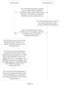
- this embodiment provides an uplink information demodulation method.
- real-time frequency offset estimation is not performed on the uplink information of the terminal device. Therefore, due to impact of a factor such as a current moving speed and channel quality of the terminal device, frequency offset calibration performed by the eNodeB on a frequency of the terminal device according to a prerecorded historical frequency offset value of the terminal device may be inaccurate, and accordingly, demodulation of the PUSCH of the terminal device is inaccurate.
- the MCS index determined by the base station according to the channel quality of the terminal device may include but is not limited to: an MCS index determined by the base station according to a CQI (Channel Quality Indicator, channel quality indicator) reported by the terminal device, an MCS index determined by the base station according to RSRP (Reference Signal Received Power, reference signal received power) reported by the terminal device, an MCS index determined by the base station according to RSRQ (Reference Signal Received Quality, reference signal received quality) reported by the terminal device, an MCS index determined by the base station according to an SRS (Sounding Reference Signal, sounding reference signal) reported by the terminal device, or an MCS index determined by the base station in another manner that may represent the channel quality of the terminal device. This is not limited herein.
- a manner of sending the second MCS index to the terminal device may include but is not limited to a PDCCH (Physical Downlink Control Channel, physical downlink control channel) or an EPDCCH (Enhanced Physical Downlink Control Channel, enhanced physical downlink control channel).
- PDCCH Physical Downlink Control Channel, physical downlink control channel
- EPDCCH Enhanced Physical Downlink Control Channel, enhanced physical downlink control channel
- the base station sends the second MCS index to the terminal device.
- the base station performs frequency offset calibration on a frequency of the terminal device according to a historical frequency offset value of the terminal device, where the historical frequency offset value is a frequency offset value of the terminal device that is stored in the base station.
- the eNodeB records a historical frequency offset value of each terminal device.
- the eNodeB may obtain the historical frequency offset value of each terminal device in the following manners:
- the eNodeB obtains the historical frequency offset value in a random access procedure performed by the terminal device, or obtains the historical frequency offset value from uplink information at a 1-millisecond transmission time interval that is sent by the terminal device.
- the eNodeB after performing specified-manner scheduling, configuration, or indication after the eNodeB detects that the terminal device reaches a first estimation threshold, the eNodeB obtains the historical frequency offset value by using uplink information sent by the terminal device.
- the eNodeB obtains the historical frequency offset value according to an uplink channel that is in a random access procedure and sent by the terminal device after the terminal device detects that the terminal device reaches a second estimation threshold.
- the base station receives uplink information sent by the terminal device according to the second MCS index, and demodulates the PUSCH according to a frequency obtained after the frequency offset calibration.
- the MCS index is selected for the terminal device
- reduction processing is performed on the MCS index according to a preset MCS index reduction exponent
- a reduced MCS index is indicated to the terminal device
- frequency offset estimation is performed on the terminal device by using the recorded historical frequency offset value
- the PUSCH sent by the terminal device according to the reduced MCS index is demodulated after the frequency offset estimation.
- Frequency calibration is performed by using the prerecorded historical frequency offset value, so that the frequency offset value does not need to be determined in an existing manner of adding a DM-RS symbol to each 0.5-millisecond TTI. Therefore, fewer reference signal resources are occupied, data transmission efficiency is improved, and reference signal system overheads are reduced.
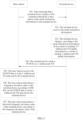
- this embodiment provides an uplink information demodulation method.
- the method includes the following steps:
- the uplink information may include a reference signal, a sounding signal, and a physical channel.
- the terminal device sends the uplink information according to a reduced MCS index, so as to reduce a rate at which the terminal device sends the uplink information to the base station.
- a reduced MCS index so as to reduce a rate at which the terminal device sends the uplink information to the base station.
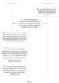
- this embodiment provides a method for determining a historical frequency offset value of a terminal device in an uplink information demodulation method.
- the method includes the following steps.
- a base station determines a frequency offset value of the terminal device according to DM-RSs on a PUSCH that is at a 1-millisecond TTI and sent by the terminal device.
- a manner of triggering the terminal device to perform 1-millisecond-TTI uplink information transmission is not limited.
- the eNodeB may determine the frequency offset value by using a phase difference between the two DM-RSs on the PUSCH sent by the terminal device at the 1-millisecond TTI.
- the base station determines a historical frequency offset value of the terminal device according to the frequency offset value of the terminal device.
- the PUSCH is a physical channel used to carry uplink data of the terminal device, and may also be used to transmit UCI (Uplink Control Information, uplink control information) of the terminal device.
- UCI Uplink Control Information, uplink control information
- a manner in which the base station determines the historical frequency offset value of the terminal device may include but is not limited to the following manner: The base station obtains, by means of calculation, the frequency offset value by using the phase difference between the two DM-RSs, and stores the frequency offset value or replaces the historical frequency offset value of the terminal device.
- the terminal device performs 1-millisecond-TTI uplink information transmission, and the historical frequency offset value of the terminal device is determined based on the DM-RSs on the PUSCH at the 1-millisecond TTI.
- the frequency offset value does not need to be determined in an existing manner of adding a DM-RS symbol to each 0.5-millisecond TTI. Therefore, fewer reference signal resources are occupied, data transmission efficiency is improved, and reference signal system overheads are reduced.
- this embodiment provides a method for determining a historical frequency offset value of a terminal device in another uplink information demodulation method.
- the method includes the following steps.
- a base station After detecting that a terminal device reaches a first estimation threshold, a base station sends at least one piece of first resource indication information to the terminal device, where the first resource indication information is used to indicate uplink frequency domain resources for PUSCHs at two 0.5-millisecond TTIs.
- That a base station detects that a terminal device reaches a first estimation threshold includes: one or more of the following parameters reach a specified threshold: a moving speed of the terminal device, a mean MCS change value of the terminal device, an MCS variance of the terminal device, a received BLER of a PUSCH of the terminal device, a quantity of HARQ (Hybrid Automatic Repeat Request, hybrid automatic repeat request) retransmission times of a PUSCH of the terminal device, an error rate or a quantity of errors of a MAC (Media Access Control, Media Access Control) packet/RLC (Radio Link Control, Radio Link Control) packet/TCP (Transmission Control Protocol, Transmission Control Protocol) packet/IP (Internet Protocol, Internet Protocol) packet of the terminal device, a quantity of ARQs (Automatic Repeat Request, automatic repeat request) of a MAC packet of the terminal device, or QoS (Quality of Service, quality of service) of a service corresponding to the terminal device.
- a MAC Media Access Control, Media Access Control
- RLC Radio
- At least one piece of resource indication information sent by the eNodeB to the terminal device may be specifically DCI (Downlink Control Information, downlink control information) or higher layer signaling.
- the higher layer signaling may include but is not limited to RNC (Radio Network Controller, radio network controller) signaling, RRC (Radio Resource Control, radio resource control) signaling, MAC signaling, or signaling carried in a broadcast message.
- RNC Radio Network Controller, radio network controller
- RRC Radio Resource Control, radio resource control
- MAC Medium Access Management Entity
- the eNodeB sends one piece of DCI or at least one piece of higher layer signaling to the terminal device by using a PDCCH or an EPDCCH at a same moment, and the one piece of DCI or the at least one piece of higher layer signaling indicates uplink frequency domain resources for PUSCHs at two 0.5-millisecond TTIs to the terminal device.
- the uplink frequency domain resources of the terminal device for the PUSCHs at the two 0.5-millisecond TTIs need to have at least one same frequency domain resource.
- the terminal device receives the at least one piece of first resource indication information, where the first resource indication information is used to indicate the uplink frequency domain resources for the PUSCHs at the two 0.5-millisecond TTIs.
- the uplink frequency domain resources for sending the PUSCHs at the two 0.5-millisecond TTIs include at least one same physical resource block PRB (Physical Resource Block, physical resource block) index or include at least one same resource block group RBG (Resource Block Group, resource block group) index, a time interval between the two 0.5-millisecond TTIs is less than or equal to n*0.5 milliseconds, and n is a non-zero positive integer.
- PRB Physical Resource Block, physical resource block
- RBG Resource Block Group, resource block group
- the terminal device sends the PUSCHs at the two 0.5-millisecond TTIs according to the first resource indication information.
- the base station receives the PUSCHs that are at the two 0.5-millisecond TTIs and sent by the terminal device, where the uplink frequency domain resources for the PUSCHs at the two 0.5-millisecond TTIs include at least one same physical resource block PRB index or include at least one same resource block group RBG index, a time interval between the two 0.5-millisecond TTIs is less than or equal to n*0.5 milliseconds, and n is a non-zero positive integer.
- this embodiment is extensible: If a time interval at which the base station receives the PUSCHs that are at the two 0.5-millisecond TTIs and sent by the terminal device is greater than n*0.5 milliseconds, and n is a non-zero positive integer, the base station does not perform step 405 and step 406, that is, does not determine or update a frequency offset value of the terminal device.
- the base station determines a frequency offset value of the terminal device according to two DM-RSs on the PUSCHs at the two 0.5-millisecond TTIs or according to two DM-RSs in frequency domains with a same PRB index or a same RBG index on the PUSCHs at the two 0.5-millisecond TTIs.
- the PUSCH is a physical channel used to carry uplink data of the terminal device, and may also be used to transmit UCI of the terminal device.
- the eNodeB may determine the frequency offset value of the terminal device according to a phase difference between the two DM-RSs on the PUSCHs at the two 0.5-millisecond TTIs, and the PUSCH at each 0.5-millisecond TTI includes one DM-RS.
- the eNodeB may determine the frequency offset value according to a phase difference between the two DM-RSs in frequency domains with the same PRB index or RBG index on the PUSCHs at the two 0.5-millisecond TTIs.
- Code sequences of the two DM-RSs in the frequency domains with the same PRB index or the same RBG index on the PUSCHs sent at the two 0.5-millisecond TTIs may not be entire code sequences of the DM-RSs, that is, are merely partial code sequences of the DM-RSs on the PUSCHs.
- the base station may determine the frequency offset value according to a phase difference between the partial code sequences of the two DM-RSs in the frequency domains with the same PRB index or the same RBG index.
- the code sequence may be any digital sequence, and is not limited herein, for example, a ZC (Zadoff-Chu) sequence.
- the base station determines a historical frequency offset value of the terminal device according to the frequency offset value of the terminal device.
- the base station determines the frequency offset value according to the phase difference between the DM-RSs at the two 0.5-ms TTIs. It may be understood that, if the two PUSCHs at the two 0.5-ms TTIs include no same frequency domain resource, the base station does not determine the frequency offset value according to the phase difference between the DM-RSs at the two 0.5-ms TTIs.
- the terminal device is instructed to send the PUSCHs at the two 0.5-millisecond TTIs, and the base station determines the historical frequency offset value of the terminal device based on the two received DM-RSs on the PUSCHs sent at the two 0.5-millisecond TTIs.
- the frequency offset value does not need to be determined in an existing manner of adding a DM-RS symbol to each 0. 5-millisecond TTI. Therefore, fewer reference signal resources are occupied, data transmission efficiency is improved, and reference signal system overheads are reduced.
- this embodiment provides a method for determining a historical frequency offset value of a terminal device in another uplink information demodulation method.
- the method includes the following steps.
- a base station After detecting that a terminal device reaches a first estimation threshold, a base station sends mode instruction information to the terminal device, where the mode instruction information is used to instruct the terminal device to change from a mode of sending 0.5-millisecond-TTI uplink information to a mode of sending 1-millisecond-TTI uplink information.
- the uplink information includes but is not limited to a PRACH (Physical Random Access Channel, physical random access channel), a PUSCH, and a PUCCH (Physical Uplink Control Channel, physical uplink control channel).
- PRACH Physical Random Access Channel
- PUSCH Physical Random Access Channel
- PUCCH Physical Uplink Control Channel
- That a base station detects that a terminal device reaches a first estimation threshold includes: one or more of the following parameters reach a specified threshold: a moving speed of the terminal device, a mean MCS change value of the terminal device, an MCS variance of the terminal device, a received BLER of a PUSCH of the terminal device, a quantity of HARQ retransmission times of a PUSCH of the terminal device, an error rate or a quantity of errors of a MAC packet/RLC packet/TCP packet/IP packet of the terminal device, a quantity of ARQs of a MAC packet of the terminal device, or QoS of a service corresponding to the terminal device.
- the terminal device receives the mode instruction information, where the mode instruction information is used to instruct the terminal device to change from the mode of sending 0.5-millisecond-TTI uplink information to the mode of sending 1-millisecond-TTI uplink information.
- the terminal device changes, according to the mode instruction information, from the mode of sending 0.5-millisecond-TTI uplink information to the mode of sending 1-millisecond-TTI uplink information.
- the terminal device changes, according to the mode instruction information, from the mode of sending 0.5-millisecond-TTI uplink information to the mode of sending 1-millisecond-TTI uplink information may be: after receiving the mode instruction information, the terminal device immediately changes to the mode of sending 1-millisecond-TTI uplink information; or may be: after X slots, the terminal device changes to the mode of sending 1-millisecond-TTI uplink information.
- X is a positive integer greater than or equal to 6.
- the base station determines a historical frequency offset value of the terminal device according to the frequency offset value of the terminal device.
- the detecting that a terminal device reaches a first estimation threshold includes: one or more of the following parameters reach a specified threshold: a moving speed of the terminal device, a mean MCS change value of the terminal device, an MCS variance of the terminal device, a received BLER of a PUSCH of the terminal device, a quantity of HARQ retransmission times of a PUSCH of the terminal device, an error rate or a quantity of errors of a MAC packet/RLC packet/TCP packet/IP packet of the terminal device, a quantity of ARQs of a MAC packet of the terminal device, or QoS of a service corresponding to the terminal device.
- the PUSCH is a physical channel used to carry uplink data of the terminal device, and may also be used to transmit UCI of the terminal device.
- the PRACH is used by the terminal to initiate communication with the base station.
- the terminal sends preamble information when performing random access.
- the base station receives and determines, by using the PRACH, an identity of the terminal that performs access; and calculates a delay of the terminal.
- this embodiment provides a method for determining a historical frequency offset value of a terminal device in another uplink information demodulation method.
- the method includes the following steps.
- a terminal device detects whether the terminal device reaches a second estimation threshold, where the second estimation threshold includes: one or more of the following parameters reach a specified threshold: a moving speed of the terminal device, a difference between an expected MCS index value and an MCS index received by the terminal device, or a difference between an MCS index received by the terminal device and an MCS index corresponding to a CQI reported by the terminal device.
- That the terminal device detects that the terminal device reaches the second estimation threshold includes: one or more of the following parameters reach the specified threshold: the moving speed of the terminal device, the difference between an expected MCS index value and an MCS index received by the terminal device, or the difference between an MCS index received by the terminal device and an MCS index corresponding to a CQI reported by the terminal device.
- the terminal device After detecting that the terminal device reaches the second estimation threshold, the terminal device sends an uplink channel in a random access procedure, where the uplink channel includes a PRACH and/or a PUSCH.
- a base station receives the uplink channel that is in the random access procedure and sent by the terminal device after the terminal device detects that the terminal device reaches the second estimation threshold, where the uplink channel includes the PRACH and/or the PUSCH, and the second estimation threshold includes: one or more of the following parameters reach the specified threshold: the moving speed of the terminal device, the difference between an expected MCS index value and an MCS index received by the terminal device, or the difference between an MCS index received by the terminal device and an MCS index corresponding to a CQI reported by the terminal device.
- the base station determines a frequency offset value of the terminal device according to the uplink channel in the random access procedure triggered by the terminal device after the terminal device detects that the terminal device reaches the second estimation threshold, where the uplink channel includes the PRACH and/or the PUSCH.
- 1-millisecond-TTI uplink information transmission is to be performed on the PRACH and/or the PUSCH sent after the terminal device triggers the random access procedure.
- the eNodeB determines the frequency offset value by using a offset of a preamble sequence on the PRACH sent by the terminal device or a phase difference between two DM-RSs on the PUSCH sent by the terminal device.
- the base station determines a historical frequency offset value of the terminal device according to the frequency offset value of the terminal device.
- the terminal device when the terminal device reaches the second estimation threshold, the terminal device triggers sending of the uplink channel in the random access procedure, and the base station determines the historical frequency offset value of the terminal device based on the uplink channel that is in the random access procedure and sent by the terminal device.
- the frequency offset value does not need to be determined in an existing manner of adding a DM-RS symbol to each 0.5-millisecond TTI. Therefore, fewer reference signal resources are occupied, data transmission efficiency is improved, and reference signal system overheads are reduced.
- this embodiment of the present invention provides a base station.
- the base station includes:
- the uplink information may include a reference signal, a sounding signal, and a physical channel.
- real-time frequency offset estimation is not performed on the uplink information of the terminal device. Therefore, due to impact of a factor such as a current moving speed and channel quality of the terminal device, frequency offset calibration performed by the eNodeB on the frequency of the terminal device according to a prerecorded historical frequency offset value of the terminal device may be inaccurate, and accordingly, demodulation of the PUSCH of the terminal device is inaccurate.
- a manner of sending the second MCS index to the terminal device may include but is not limited to a PDCCH or an EPDCCH.
- the MCS index determined by the base station according to the channel quality of the terminal device may include but is not limited to: an MCS index determined by the base station according to a CQI reported by the terminal device, an MCS index determined by the base station according to RSRP reported by the terminal device, an MCS index determined by the base station according to RSRQ reported by the terminal device, an MCS index determined by the base station according to an SRS reported by the terminal device, or an MCS index determined by the base station in another manner that may represent the channel quality of the terminal device. This is not limited herein.
- the base station in this embodiment may implement the procedure in the embodiment shown in FIG. 1 .
- the first determining module 902 is further configured to: after the terminal device performs 1-millisecond-TTI uplink information transmission, determine a frequency offset value of the terminal device according to DM-RSs on a PUSCH that is at a 1-millisecond TTI and sent by the terminal device.
- the first determining module 902 is further configured to determine the historical frequency offset value of the terminal device according to the frequency offset value of the terminal device.
- the PUSCH is a physical channel used to carry uplink data of the terminal device, and may also be used to transmit UCI of the terminal device.
- a manner in which the base station determines the historical frequency offset value of the terminal device may include but is not limited to the following manner: The base station obtains, by means of calculation, the frequency offset value by using a phase difference between the two DM-RSs, and stores the frequency offset value or replaces the historical frequency offset value of the terminal device.
- the base station in this embodiment may implement the procedure in the embodiment shown in FIG. 3 .
- the first sending module 903 is further configured to: after it is detected that the terminal device reaches a first estimation threshold, send at least one piece of first resource indication information to the terminal device.
- the first resource indication information is used to indicate uplink frequency domain resources for PUSCHs at two 0. 5-millisecond TTIs.
- That it is detected that the terminal device reaches a first estimation threshold includes: one or more of the following parameters reach a specified threshold: a moving speed of the terminal device, a mean MCS change value of the terminal device, an MCS variance of the terminal device, the received BLER of the PUSCH of the terminal device, a quantity of hybrid automatic repeat request HARQ retransmission times of a PUSCH of the terminal device, an error rate or a quantity of errors of a Media Access Control MAC packet/Radio Link Control RLC packet/Transmission Control Protocol TCP packet/Internet Protocol IP packet of the terminal device, a quantity of automatic repeat requests ARQs of a MAC packet of the terminal device, or quality of service QoS of a service corresponding to the terminal device.
- a moving speed of the terminal device a mean MCS change value of the terminal device, an MCS variance of the terminal device, the received BLER of the PUSCH of the terminal device, a quantity of hybrid automatic repeat request HARQ retransmission times of a PUSCH of the terminal device
- the first receiving module 905 is further configured to receive the PUSCHs that are at the two 0.5-millisecond TTIs and sent by the terminal device.
- the uplink frequency domain resources for the PUSCHs at the two 0.5-millisecond TTIs include at least one same physical resource block PRB index or include at least one same resource block group RBG index, a time interval between the two 0.5-millisecond TTIs is less than or equal to n*0.5 milliseconds, and n is a non-zero positive integer.
- this embodiment is extensible: If a time interval at which the PUSCHs that are at the two 0.5-millisecond TTIs and sent by the terminal device is greater than n*0.5 milliseconds, and n is a non-zero positive integer, the base station does not perform, by using the first determining module 902, the steps of determining or updating the frequency offset value of the terminal device.
- the first determining module 902 is further configured to determine a frequency offset value of the terminal device according to two DM-RSs on the PUSCHs at the two 0.5-millisecond TTIs or according to two DM-RSs in frequency domains with a same PRB index or a same RBG index on the PUSCHs at the two 0. 5-millisecond TTIs.
- the first determining module 902 is further configured to determine the historical frequency offset value of the terminal device according to the frequency offset value of the terminal device.
- the eNodeB may determine the frequency offset value of the terminal device according to a phase difference between the two DM-RSs on the PUSCHs at the two 0.5-millisecond TTIs.
- the PUSCH at each 0.5-millisecond TTI includes one DM-RS.
- the eNodeB may determine the frequency offset value according to a phase difference between the two DM-RSs in frequency domains with the same PRB index or RBG index on the PUSCHs at the two 0.5-millisecond TTIs.
- Code sequences of the two DM-RSs in the frequency domains with the same PRB index or the same RBG index on the PUSCHs sent at the two 0.5-millisecond TTIs may not be entire code sequences of the DM-RSs, that is, are merely partial code sequences of the DM-RSs on the PUSCHs.
- the base station may determine the frequency offset value according to a phase difference between the partial code sequences of the two DM-RSs in the frequency domains with the same PRB index or the same RBG index.
- the code sequence may be any digital sequence, and is not limited herein, for example, a ZC (Zadoff-Chu) sequence.
- the PUSCH is a physical channel used to carry uplink data of the terminal device, and may also be used to transmit UCI of the terminal device.
- the base station in this embodiment may implement the procedure implemented on a base station side in the embodiment shown in FIG. 4 .
- the first sending module 903 is further configured to: after it is detected that the terminal device reaches a first estimation threshold, send mode instruction information to the terminal device.
- the mode instruction information is used to instruct the terminal device to change from a mode of sending 0.5-millisecond-TTI uplink information to a mode of sending 1-millisecond-TTI uplink information.
- That it is detected that the terminal device reaches a first estimation threshold includes: one or more of the following parameters reach a specified threshold: a moving speed of the terminal device, a mean MCS change value of the terminal device, an MCS variance of the terminal device, the received BLER of the PUSCH of the terminal device, a quantity of HARQ retransmission times of a PUSCH of the terminal device, an error rate or a quantity of errors of a MAC packet/RLC packet/TCP packet/IP packet of the terminal device, a quantity of ARQs of a MAC packet of the terminal device, or QoS of a service corresponding to the terminal device.
- the first receiving module 905 is further configured to receive a PUSCH that is at a 1-millisecond TTI and sent by the terminal device.
- the first determining module 902 is further configured to determine a frequency offset value of the terminal device according to DM-RSs on the PUSCH that is at the 1-millisecond TTI and sent by the terminal device.
- the first determining module 902 is further configured to determine the historical frequency offset value of the terminal device according to the frequency offset value of the terminal device.
- the PUSCH is a physical channel used to carry uplink data of the terminal device, and may also be used to transmit UCI of the terminal device.
- the base station in this embodiment may implement the procedure implemented on a base station side in the embodiment shown in FIG. 5 .
- the first sending module 903 is further configured to: after it is detected that the terminal device reaches a first estimation threshold, send at least one piece of second resource indication information to the terminal device within a preset time interval contiguous to a moment at which the terminal device sends a sounding reference signal SRS.
- the second resource indication information is used to indicate an uplink frequency domain resource for a PUSCH at a 0.5-millisecond TTI.
- That it is detected that the terminal device reaches a first estimation threshold includes: one or more of the following parameters reach a specified threshold: a moving speed of the terminal device, a mean MCS change value of the terminal device, an MCS variance of the terminal device, the received BLER of the PUSCH of the terminal device, a quantity of HARQ retransmission times of a PUSCH of the terminal device, an error rate or a quantity of errors of a MAC packet/RLC packet/TCP packet/IP packet of the terminal device, a quantity of ARQs of a MAC packet of the terminal device, or QoS of a service corresponding to the terminal device.
- the first receiving module 905 is further configured to: receive the PUSCH that is at the 0.5-millisecond TTI and sent by the terminal device, and receive the SRS sent by the terminal device.
- the uplink frequency domain resource for the PUSCH sent at the 0.5-millisecond TTI includes at least one same frequency domain resource as an uplink frequency domain resource on which the SRS is located, the preset time interval is less than or equal to m*0.5 milliseconds, and m is a non-zero integer.
- the eNodeB sends DCI to the terminal device by using a PDCCH or an EPDCCH, and indicates the uplink frequency domain resource for the PUSCH at the 0.5-millisecond TTI to the terminal device in the DCI.
- the uplink frequency domain resource of the terminal device for the PUSCH at the 0.5-millisecond TTI needs to have a same frequency domain resource as the SRS sent by the terminal device.
- the PUSCH is a physical channel used to carry uplink data of the terminal device, and may also be used to transmit UCI of the terminal device.
- the eNodeB knows a sending time of a periodic or aperiodic SRS (Sounding Reference Signal, sounding reference signal) of each terminal device. Therefore, within a preset time interval before or after the terminal device sends the SRS, the eNodeB may schedule the terminal device to send a PUSCH, so that an uplink frequency domain resource on which the terminal device sends the SRS has a same frequency domain resource as an uplink frequency domain resource on which the terminal device is scheduled to send the PUSCH, thereby determining a frequency offset value of the terminal device.
- SRS Sounding Reference Signal
- the first determining module 902 is further configured to determine a frequency offset value of the terminal device according to the SRS and a DM-RS on the PUSCH at the 0.5-millisecond TTI or according to a DM-RS and an SRS that are on the same frequency domain resource in the SRS as on the PUSCH at the 0.5-millisecond TTI.
- the eNodeB determines the frequency offset value according to a phase difference between the uplink frequency domain resource for the SRS sent by the terminal device and the DM-RS on the PUSCH sent by the terminal device at the 0.5-millisecond TTI.
- the eNodeB determines the frequency offset value according to a phase difference between the uplink frequency domain resource for the SRS sent by the terminal device and the DM-RS in a frequency domain with the same PRB index or the same RBG index of the terminal device at the 0.5-millisecond TTI.
- the uplink frequency domain resource for the SRS includes an entire code sequence of the SRS.
- the PUSCH sent by the terminal device at the 0.5-millisecond TTI includes an entire code sequence of the DM-RS.
- the base station may determine the frequency offset value according to a phase difference between the two code sequences.
- a code sequence of the DM-RS on the frequency domain resource with the same PRB index or the same RBG index in the SRS as on the PUSCH sent at the 0.5-millisecond TTI may not be an entire code sequence of the DM-RS, that is, is merely a partial code sequence of the DM-RS on the PUSCH.
- a code sequence of the SRS in the frequency domain with the same PRB index or the same RBG index in the SRS as on the PUSCH sent at the 0.5-millisecond TTI may not be an entire code sequence of the SRS, that is, is merely a partial code sequence of the SRS on the PUSCH.
- the terminal device determines the frequency offset value according to a phase difference between the code sequence of the SRS and the code sequence of the DM-RS.
- the code sequence of the SRS may be the entire code sequence of the SRS, or may be the partial code sequence of the SRS.
- the code sequence of the DM-RS may be the entire code sequence of the DM-RS, or may be the partial code sequence of the DM-RS.
- the code sequence may be any digital sequence, and is not limited herein, for example, a ZC (Zadoff-Chu) sequence.
- the first determining module 902 is further configured to determine the historical frequency offset value of the terminal device according to the frequency offset value of the terminal device.
- this embodiment is extensible: If a time interval between a moment at which the base station receives the PUSCH that is at the 0.5-millisecond TTI and sent by the terminal device and a moment at which the base station receives the SRS sent by the terminal device is greater than m*0.5 milliseconds, and m is a non-zero integer, the base station does not perform the module procedure steps by using the first determining module 902, that is, does not determine or update the frequency offset value of the terminal device.
- the base station in this embodiment may implement the procedure implemented on a base station side in the embodiment shown in FIG. 6 .
- the first sending module 903 is further configured to: after it is detected that the terminal device reaches a first estimation threshold, send random access procedure indication information to the terminal device by using a physical downlink control channel PDCCH. That it is detected that the terminal device reaches a first estimation threshold includes: one or more of the following parameters reach a specified threshold: a moving speed of the terminal device, a mean MCS change value of the terminal device, an MCS variance of the terminal device, the received BLER of the PUSCH of the terminal device, a quantity of HARQ retransmission times of a PUSCH of the terminal device, an error rate or a quantity of errors of a MAC packet/RLC packet/TCP packet/IP packet of the terminal device, a quantity of ARQs of a MAC packet of the terminal device, or QoS of a service corresponding to the terminal device.
- a first estimation threshold includes: one or more of the following parameters reach a specified threshold: a moving speed of the terminal device, a mean MCS change value of the terminal device,
- the first receiving module 905 is further configured to receive an uplink channel that is in a random access procedure and sent by the terminal device according to the random access procedure indication information.
- the first determining module 902 is further configured to determine a frequency offset value of the terminal device according to a DM-RS and/or a preamble sequence on the uplink channel that is in the random access procedure and sent by the terminal device.
- the uplink channel includes a physical random access channel PRACH and/or a PUSCH.
- the first determining module 902 is further configured to determine the historical frequency offset value of the terminal device according to the frequency offset value of the terminal device.
- 1-millisecond-TTI uplink information transmission is to be performed on the PRACH and/or the PUSCH sent after the terminal device triggers the random access procedure.
- the eNodeB determines the frequency offset value by using a offset of a preamble sequence on the PRACH sent by the terminal device or a phase difference between two DM-RSs on the PUSCH sent by the terminal device.
- the base station determines an uplink frequency offset value of the terminal device according to a offset status of the preamble sequence in the random access procedure.
- the PUSCH is a physical channel used to carry uplink data of the terminal device, and may also be used to transmit UCI of the terminal device.
- the PRACH is used by the terminal to initiate communication with the base station.
- the terminal sends preamble information when performing random access.
- the base station receives and determines, by using the PRACH, an identity of the terminal that performs access; and calculates a delay of the terminal.
- the base station in this embodiment may implement the procedure implemented on a base station side in the embodiment shown in FIG. 7 .
- the first receiving module 905 is further configured to receive an uplink channel that is in a random access procedure and sent by the terminal device after the terminal device detects that the terminal device reaches a second estimation threshold.
- the uplink channel includes a PRACH and/or a PUSCH.
- the second estimation threshold includes: one or more of the following parameters reach a specified threshold: a moving speed of the terminal device, a difference between an expected MCS index value and an MCS index received by the terminal device, or a difference between an MCS index received by the terminal device and an MCS index corresponding to a CQI reported by the terminal device.
- the first determining module 902 is further configured to determine a frequency offset value of the terminal device according to the uplink channel in the random access procedure triggered by the terminal device after the terminal device detects that the terminal device reaches the second estimation threshold.
- the uplink channel includes the PRACH and/or the PUSCH.
- the first determining module 902 is further configured to determine the historical frequency offset value of the terminal device according to the frequency offset value of the terminal device.
- the PUSCH is a physical channel used to carry uplink data of the terminal device, and may also be used to transmit UCI of the terminal device.
- the PRACH is used by the terminal to initiate communication with the base station.
- the terminal sends preamble information when performing random access.
- the base station receives and determines, by using the PRACH, an identity of the terminal that performs access; and calculates a delay of the terminal.
- the base station in this embodiment may implement the procedure implemented on a base station side in the embodiment shown in FIG. 8 .
- reduction processing is performed on the MCS index according to a preset MCS index reduction exponent, a reduced MCS index is indicated to the terminal device, frequency offset estimation is performed on the terminal device by using the recorded historical frequency offset value, and the PUSCH sent by the terminal device according to the reduced MCS index is demodulated after the frequency offset estimation.
- Frequency calibration is performed by using the prerecorded historical frequency offset value, so that the frequency offset value does not need to be determined in an existing manner of adding a DM-RS symbol to a 0.5-millisecond TTI. Therefore, fewer resources are occupied, data transmission efficiency is improved, and reference signal system overheads are reduced.
- the terminal device performs 1-millisecond-TTI uplink information transmission, and the historical frequency offset value of the terminal device is determined based on the DM-RSs on the PUSCH at the 1-millisecond TTI.
- the terminal device is instructed to send the PUSCHs at the two 0.5-millisecond TTIs, and the base station determines the historical frequency offset value of the terminal device based on the two received DM-RSs on the PUSCHs sent at the two 0.5-millisecond TTIs.
- the terminal device is instructed to send the PUSCH at the 1-millisecond TTI, and the base station determines the historical frequency offset value of the terminal device based on the two received DM-RSs on the PUSCH at the 1-millisecond TTI.
- the terminal device is instructed to send the PUSCH at the 0.5-millisecond TTI and send the SRS, and the base station determines the historical frequency offset value of the terminal device based on the received SRS and the received DM-RS on the PUSCH at the 0.5-millisecond TTI.
- the terminal device is instructed to send the uplink channel in the random access procedure, and the base station determines the historical frequency offset value of the terminal device based on the received DM-RSs on the uplink channel that is in the random access procedure and sent by the terminal device.
- the terminal device when the terminal device reaches the second estimation threshold, the terminal device triggers sending of the uplink channel in the random access procedure, and the base station determines the historical frequency offset value of the terminal device based on the uplink channel that is in the random access procedure and sent by the terminal device.
- the base station determines the historical frequency offset value in the foregoing manners, so that the frequency offset value does not need to be determined in the existing manner of adding a DM-RS symbol to a 0.5-millisecond TTI. Therefore, fewer resources are occupied, data transmission efficiency is improved, and reference signal system overheads are reduced.
- this embodiment provides a terminal device.
- the uplink information may include a reference signal, a sounding signal, and a physical channel.
- the terminal device in this embodiment may implement the procedure in the embodiment shown in FIG. 2 .
- the second receiving module 1001 is further configured to receive at least one piece of first resource indication information.
- the first resource indication information is used to indicate uplink frequency domain resources for PUSCHs at two 0.5-millisecond TTIs, the uplink frequency domain resources for sending the PUSCHs at the two 0.5-millisecond TTIs include at least one same physical resource block PRB index or include at least one same resource block group RBG index, a time interval between the two 0.5-millisecond TTIs is less than or equal to n*0.5 milliseconds, and n is a non-zero positive integer.
- the second sending module 1002 is further configured to send the PUSCHs at the two 0.5-millisecond TTIs according to the first resource indication information.
- the PUSCH is a physical channel used to carry uplink data of the terminal device, and may also be used to transmit UCI of the terminal device.
- the terminal device in this embodiment may implement the procedure implemented on a terminal device side in the embodiment shown in FIG. 4 .
- the apparatus further includes a change module 1003.
- the second receiving module 1001 is further configured to receive mode instruction information.
- the mode instruction information is used to instruct the terminal device to change from a mode of sending 0.5-millisecond-TTI uplink information to a mode of sending 1-millisecond-TTI uplink information.
- the terminal device changes, according to the mode instruction information, from the mode of sending 0.5-millisecond-TTI uplink information to the mode of sending 1-millisecond-TTI uplink information may be: after receiving the mode instruction information, the terminal device immediately changes to the mode of sending 1-millisecond-TTI uplink information; or may be: after X slots, the terminal device changes to the mode of sending 1-millisecond-TTI uplink information.
- X is a positive integer greater than or equal to 6.
- the change module 1003 is configured to change, according to the mode instruction information, from the mode of sending 0.5-millisecond-TTI uplink information to the mode of sending 1-millisecond-TTI uplink information.
- the second sending module 1002 is further configured to send a PUSCH at a 1-millisecond TTI.
- the PUSCH is a physical channel used to carry uplink data of the terminal device, and may also be used to transmit UCI of the terminal device.
- the terminal device in this embodiment may implement the procedure implemented on a terminal device side in the embodiment shown in FIG. 5 .
- the second receiving module 1001 is further configured to receive at least one piece of second resource indication information.
- the second resource indication information is used to indicate an uplink frequency domain resource for a PUSCH at a 0.5-millisecond TTI.
- the second sending module 1002 is further configured to: send the PUSCH at the 0.5-millisecond TTI according to the second resource indication information, and send an SRS.
- the uplink frequency domain resource for the PUSCH sent at the 0.5-millisecond TTI includes at least one same PRB index or includes at least one same RBG index as an uplink frequency domain resource on which the SRS is located, a preset time interval is less than or equal to m*0.5 milliseconds, and m is a non-zero integer.
- m is a negative integer, it indicates that the PUSCH is sent before a symbol on which the SRS is located. If m is a positive integer, it indicates that the PUSCH is sent after a symbol on which the SRS is located.
- the PUSCH is a physical channel used to carry uplink data of the terminal device, and may also be used to transmit UCI of the terminal device.
- the terminal device in this embodiment may implement the procedure implemented on a terminal device side in the embodiment shown in FIG. 6 .
- the second receiving module 1001 is further configured to receive random access procedure indication information sent by using a PDCCH.
- the second sending module 1002 is further configured to send an uplink channel in a random access procedure according to the random access procedure indication information.
- the uplink channel includes a PRACH and/or a PUSCH.
- 1-millisecond-TTI uplink information transmission is to be performed on the PRACH and/or the PUSCH sent after the terminal device triggers the random access procedure.
- the PUSCH is a physical channel used to carry uplink data of the terminal device, and may also be used to transmit UCI of the terminal device.
- the PRACH is used by the terminal to initiate communication with the base station.
- the terminal sends preamble information when performing random access.
- the base station receives and determines, by using the PRACH, an identity of the terminal that performs access; and calculates a delay of the terminal.
- the terminal device in this embodiment may implement the procedure implemented on a terminal device side in the embodiment shown in FIG. 7 .
- the apparatus further includes a detection module 1004.
- the terminal device in this embodiment may implement the procedure implemented on a terminal device side in the embodiment shown in FIG. 8 .
- this embodiment of the present invention provides a base station.
- the receiver 1103 is configured to receive uplink information sent by the terminal device according to the second MCS index.
- the uplink information may include a reference signal, a sounding signal, and a physical channel.
- the processor 1101 is further configured to: after the terminal device performs 1-millisecond-TTI uplink information transmission, determine a frequency offset value of the terminal device according to DM-RSs on a PUSCH that is at a 1-millisecond TTI and sent by the terminal device; and determine the historical frequency offset value of the terminal device according to the frequency offset value of the terminal device.
- the base station in this embodiment may implement the procedure in the embodiment shown in FIG. 3 .
- a manner in which the base station determines the historical frequency offset value of the terminal device may include but is not limited to the following manner: The base station obtains, by means of calculation, the frequency offset value by using a phase difference between the two DM-RSs, and stores the frequency offset value or replaces the historical frequency offset value of the terminal device.
- the transmitter 1102 is further configured to: after it is detected that the terminal device reaches a first estimation threshold, send at least one piece of first resource indication information to the terminal device.
- the first resource indication information is used to indicate uplink frequency domain resources for PUSCHs at two 0.5-millisecond TTIs.
- That it is detected that the terminal device reaches a first estimation threshold includes: one or more of the following parameters reach a specified threshold: a moving speed of the terminal device, a mean MCS change value of the terminal device, an MCS variance of the terminal device, the received BLER of the PUSCH of the terminal device, a quantity of hybrid automatic repeat request HARQ retransmission times of a PUSCH of the terminal device, an error rate or a quantity of errors of a Media Access Control MAC packet/Radio Link Control RLC packet/Transmission Control Protocol TCP packet/Internet Protocol IP packet of the terminal device, a quantity of automatic repeat requests ARQs of a MAC packet of the terminal device, or quality of service QoS of a service corresponding to the terminal device.
- a moving speed of the terminal device a mean MCS change value of the terminal device, an MCS variance of the terminal device, the received BLER of the PUSCH of the terminal device, a quantity of hybrid automatic repeat request HARQ retransmission times of a PUSCH of the terminal device
- the receiver 1103 is further configured to receive the PUSCHs that are at the two 0.5-millisecond TTIs and sent by the terminal device.
- the uplink frequency domain resources for the PUSCHs at the two 0.5-millisecond TTIs include at least one same physical resource block PRB index or include at least one same resource block group RBG index, a time interval between the two 0.5-millisecond TTIs is less than or equal to n*0.5 milliseconds, and n is a non-zero positive integer.
- the processor 1101 is further configured to: determine a frequency offset value of the terminal device according to two DM-RSs on the PUSCHs at the two 0.5-millisecond TTIs or according to two DM-RSs in frequency domains with a same PRB index or a same RBG index on the PUSCHs at the two 0.5-millisecond TTIs; and determine the historical frequency offset value of the terminal device according to the frequency offset value of the terminal device.
- the eNodeB may determine the frequency offset value of the terminal device according to a phase difference between the two DM-RSs on the PUSCHs at the two 0.5-millisecond TTIs.
- the PUSCH at each 0.5-millisecond TTI includes one DM-RS.
- the eNodeB may determine the frequency offset value according to a phase difference between the two DM-RSs in frequency domains with the same PRB index or RBG index on the PUSCHs at the two 0.5-millisecond TTIs.
- Code sequences of the two DM-RSs in the frequency domains with the same PRB index or the same RBG index on the PUSCHs sent at the two 0.5-millisecond TTIs may not be entire code sequences of the DM-RSs, that is, are merely partial code sequences of the DM-RSs on the PUSCHs.
- the base station may determine the frequency offset value according to a phase difference between the partial code sequences of the two DM-RSs in the frequency domains with the same PRB index or the same RBG index.
- the code sequence may be any digital sequence, and is not limited herein, for example, a ZC (Zadoff-Chu) sequence.
- the PUSCH is a physical channel used to carry uplink data of the terminal device, and may also be used to transmit UCI of the terminal device.
- the base station in this embodiment may implement the procedure implemented on a base station side in the embodiment shown in FIG. 4 .
- this embodiment is extensible: If a time interval at which the PUSCHs that are at the two 0.5-millisecond TTIs and sent by the terminal device is greater than n*0.5 milliseconds, and n is a non-zero positive integer, the processor does not perform the steps of determining or updating the frequency offset value of the terminal device.
- the transmitter 1102 is further configured to: after it is detected that the terminal device reaches a first estimation threshold, send mode instruction information to the terminal device.
- the mode instruction information is used to instruct the terminal device to change from a mode of sending 0.5-millisecond-TTI uplink information to a mode of sending 1-millisecond-TTI uplink information.
- That it is detected that the terminal device reaches a first estimation threshold includes: one or more of the following parameters reach a specified threshold: a moving speed of the terminal device, a mean MCS change value of the terminal device, an MCS variance of the terminal device, the received BLER of the PUSCH of the terminal device, a quantity of HARQ retransmission times of a PUSCH of the terminal device, an error rate or a quantity of errors of a MAC packet/RLC packet/TCP packet/IP packet of the terminal device, a quantity of ARQs of a MAC packet of the terminal device, or QoS of a service corresponding to the terminal device.
- the receiver 1103 is further configured to receive a PUSCH that is at a 1-millisecond TTI and sent by the terminal device.
- the processor 1101 is further configured to: determine a frequency offset value of the terminal device according to DM-RSs on the PUSCH that is at the 1-millisecond TTI and sent by the terminal device; and determine the historical frequency offset value of the terminal device according to the frequency offset value of the terminal device.
- the PUSCH is a physical channel used to carry uplink data of the terminal device, and may also be used to transmit UCI of the terminal device.
- the base station in this embodiment may implement the procedure implemented on a base station side in the embodiment shown in FIG. 5 .
- the transmitter 1102 is further configured to: after it is detected that the terminal device reaches a first estimation threshold, send at least one piece of second resource indication information to the terminal device within a preset time interval contiguous to a moment at which the terminal device sends a sounding reference signal SRS.
- the second resource indication information is used to indicate an uplink frequency domain resource for a PUSCH at a 0.5-millisecond TTI.
- That it is detected that the terminal device reaches a first estimation threshold includes: one or more of the following parameters reach a specified threshold: a moving speed of the terminal device, a mean MCS change value of the terminal device, an MCS variance of the terminal device, the received BLER of the PUSCH of the terminal device, a quantity of HARQ retransmission times of a PUSCH of the terminal device, an error rate or a quantity of errors of a MAC packet/RLC packet/TCP packet/IP packet of the terminal device, a quantity of ARQs of a MAC packet of the terminal device, or QoS of a service corresponding to the terminal device.
- the receiver 1103 is further configured to: receive the PUSCH that is at the 0.5-millisecond TTI and sent by the terminal device, and receive the SRS sent by the terminal device.
- the uplink frequency domain resource for the PUSCH sent at the 0.5-millisecond TTI includes at least one same frequency domain resource as an uplink frequency domain resource on which the SRS is located, the preset time interval is less than or equal to m*0.5 milliseconds, and m is a non-zero integer.
- the processor 1101 is further configured to: determine a frequency offset value of the terminal device according to the SRS and a DM-RS on the PUSCH at the 0.5-millisecond TTI or according to a DM-RS and an SRS that are on the same frequency domain resource in the SRS as on the PUSCH at the 0.5-millisecond TTI; and determine the historical frequency offset value of the terminal device according to the frequency offset value of the terminal device.
- the eNodeB sends DCI to the terminal device by using a PDCCH or an EPDCCH, and indicates the uplink frequency domain resource for the PUSCH at the 0.5-millisecond TTI to the terminal device in the DCI.
- the uplink frequency domain resource of the terminal device for the PUSCH at the 0.5-millisecond TTI needs to have a same frequency domain resource as the SRS sent by the terminal device.
- the eNodeB knows a sending time of a periodic or aperiodic SRS of each terminal device. Therefore, within a preset time interval before or after the terminal device sends the SRS, the eNodeB may schedule the terminal device to send a PUSCH, so that an uplink frequency domain resource on which the terminal device sends the SRS has a same frequency domain resource as an uplink frequency domain resource on which the terminal device is scheduled to send the PUSCH, thereby determining the frequency offset value of the terminal device.
- the eNodeB determines the frequency offset value according to a phase difference between the uplink frequency domain resource for the SRS sent by the terminal device and the DM-RS on the PUSCH sent by the terminal device at the 0.5-millisecond TTI.
- the eNodeB determines the frequency offset value according to a phase difference between the uplink frequency domain resource for the SRS sent by the terminal device and the DM-RS in a frequency domain with the same PRB index or the same RBG index of the terminal device at the 0.5-millisecond TTI.
- the uplink frequency domain resource for the SRS includes an entire code sequence of the SRS.
- the PUSCH sent by the terminal device at the 0.5-millisecond TTI includes an entire code sequence of the DM-RS.
- the base station may determine the frequency offset value according to a phase difference between the two code sequences.
- a code sequence of the DM-RS on the frequency domain resource with the same PRB index or the same RBG index in the SRS as on the PUSCH sent at the 0.5-millisecond TTI may not be an entire code sequence of the DM-RS, that is, is merely a partial code sequence of the DM-RS on the PUSCH.
- a code sequence of the SRS in the frequency domain with the same PRB index or the same RBG index in the SRS as on the PUSCH sent at the 0. 5-millisecond TTI may not be an entire code sequence of the SRS, that is, is merely a partial code sequence of the SRS on the PUSCH.
- the terminal device determines the frequency offset value according to a phase difference between the code sequence of the SRS and the code sequence of the DM-RS.
- the code sequence of the SRS may be the entire code sequence of the SRS, or may be the partial code sequence of the SRS.
- the code sequence of the DM-RS may be the entire code sequence of the DM-RS, or may be the partial code sequence of the DM-RS.
- the code sequence may be any digital sequence, and is not limited herein, for example, a ZC (Zadoff-Chu) sequence.
- the PUSCH is a physical channel used to carry uplink data of the terminal device, and may also be used to transmit UCI of the terminal device.
- the base station in this embodiment may implement the procedure implemented on a base station side in the embodiment shown in FIG. 6 .
- the transmitter 1102 is further configured to: after it is detected that the terminal device reaches a first estimation threshold, send random access procedure indication information to the terminal device by using a physical downlink control channel PDCCH. That it is detected that the terminal device reaches a first estimation threshold includes: one or more of the following parameters reach a specified threshold: a moving speed of the terminal device, a mean MCS change value of the terminal device, an MCS variance of the terminal device, the received BLER of the PUSCH of the terminal device, a quantity of HARQ retransmission times of a PUSCH of the terminal device, an error rate or a quantity of errors of a MAC packet/RLC packet/TCP packet/IP packet of the terminal device, a quantity of ARQs of a MAC packet of the terminal device, or QoS of a service corresponding to the terminal device.
- a first estimation threshold includes: one or more of the following parameters reach a specified threshold: a moving speed of the terminal device, a mean MCS change value of the terminal device, an M
- the receiver 1103 is further configured to receive an uplink channel that is in a random access procedure and sent by the terminal device according to the random access procedure indication information.
- the processor 1101 is further configured to: determine a frequency offset value of the terminal device according to a DM-RS and/or a preamble sequence on the uplink channel that is in the random access procedure and sent by the terminal device, where the uplink channel includes a physical random access channel PRACH and/or a PUSCH; and determine the historical frequency offset value of the terminal device according to the frequency offset value of the terminal device.
- 1-millisecond-TTI uplink information transmission is to be performed on the PRACH and/or the PUSCH sent after the terminal device triggers the random access procedure.
- the eNodeB determines the frequency offset value by using a offset of a preamble sequence on the PRACH sent by the terminal device or a phase difference between two DM-RSs on the PUSCH sent by the terminal device.
- the base station determines an uplink frequency offset value of the terminal device according to a offset status of the preamble sequence in the random access procedure.
- the PUSCH is a physical channel used to carry uplink data of the terminal device, and may also be used to transmit UCI of the terminal device.
- the PRACH is used by the terminal to initiate communication with the base station.
- the terminal sends preamble information when performing random access.
- the base station receives and determines, by using the PRACH, an identity of the terminal that performs access; and calculates a delay of the terminal.
- the base station in this embodiment may implement the procedure implemented on a base station side in the embodiment shown in FIG. 7 .
- the receiver 1103 is further configured to receive an uplink channel that is in a random access procedure and sent by the terminal device after the terminal device detects that the terminal device reaches a second estimation threshold.
- the uplink channel includes a PRACH and/or a PUSCH.
- the second estimation threshold includes: one or more of the following parameters reach a specified threshold: a moving speed of the terminal device, a difference between an expected MCS index value and an MCS index received by the terminal device, or a difference between an MCS index received by the terminal device and an MCS index corresponding to a CQI reported by the terminal device.
- the processor 1101 is further configured to: determine a frequency offset value of the terminal device according to the uplink channel in the random access procedure triggered by the terminal device after the terminal device detects that the terminal device reaches the second estimation threshold, where the uplink channel includes the PRACH and/or the PUSCH; and determine the historical frequency offset value of the terminal device according to the frequency offset value of the terminal device.
- the PUSCH is a physical channel used to carry uplink data of the terminal device, and may also be used to transmit UCI of the terminal device.
- the PRACH is used by the terminal to initiate communication with the base station.
- the terminal sends preamble information when performing random access.
- the base station receives and determines, by using the PRACH, an identity of the terminal that performs access; and calculates a delay of the terminal.
- the base station in this embodiment may implement the procedure implemented on a base station side in the embodiment shown in FIG. 8 .
- reduction processing is performed on the MCS index according to a preset MCS index reduction exponent, a reduced MCS index is indicated to the terminal device, frequency offset estimation is performed on the terminal device by using the recorded historical frequency offset value, and the PUSCH sent by the terminal device according to the reduced MCS index is demodulated after the frequency offset estimation.
- Frequency calibration is performed by using the prerecorded historical frequency offset value, so that the frequency offset value does not need to be determined in an existing manner of adding a DM-RS symbol to a 0.5-millisecond TTI. Therefore, fewer resources are occupied, data transmission efficiency is improved, and reference signal system overheads are reduced.
- the terminal device performs 1-millisecond-TTI uplink information transmission, and the historical frequency offset value of the terminal device is determined based on the DM-RSs on the PUSCH at the 1-millisecond TTI.
- the terminal device is instructed to send the PUSCHs at the two 0.5-millisecond TTIs, and the base station determines the historical frequency offset value of the terminal device based on the two received DM-RSs on the PUSCHs sent at the two 0.5-millisecond TTIs.
- the terminal device is instructed to send the PUSCH at the 1-millisecond TTI, and the base station determines the historical frequency offset value of the terminal device based on the two received DM-RSs on the PUSCH at the 1-millisecond TTI.
- the terminal device is instructed to send the PUSCH at the 0.5-millisecond TTI and send the SRS, and the base station determines the historical frequency offset value of the terminal device based on the received SRS and the received DM-RS on the PUSCH at the 0.5-millisecond TTI.
- the terminal device is instructed to send the uplink channel in the random access procedure, and the base station determines the historical frequency offset value of the terminal device based on the received DM-RSs on the uplink channel that is in the random access procedure and sent by the terminal device.
- the terminal device when the terminal device reaches the second estimation threshold, the terminal device triggers sending of the uplink channel in the random access procedure, and the base station determines the historical frequency offset value of the terminal device based on the uplink channel that is in the random access procedure and sent by the terminal device.
- the base station determines the historical frequency offset value in the foregoing manners, so that the frequency offset value does not need to be determined in the existing manner of adding a DM-RS symbol to a 0.5-millisecond TTI. Therefore, fewer resources are occupied, data transmission efficiency is improved, and reference signal system overheads are reduced.
- this embodiment provides a terminal device.
- the terminal device includes a transmitter 1201 and a receiver 1202.
- the receiver 1202 is configured to receive a second modulation and coding scheme MCS index, where the second MCS index is obtained after a base station performs reduction processing on a first MCS index according to an MCS index reduction value, and the first MCS index is selected by the base station according to channel quality of the terminal device and/or a received target block error rate BLER of a physical uplink shared channel PUSCH of the terminal device.
- the transmitter 1201 is configured to send uplink information according to the second MCS index.
- the uplink information may include a reference signal, a sounding signal, and a physical channel.
- the terminal device in this embodiment may implement the procedure in the embodiment shown in FIG. 2 .
- the receiver 1202 is further configured to receive at least one piece of first resource indication information.
- the first resource indication information is used to indicate uplink frequency domain resources for PUSCHs at two 0.5-millisecond TTIs, the uplink frequency domain resources for sending the PUSCHs at the two 0.5-millisecond TTIs include at least one same physical resource block PRB index or include at least one same resource block group RBG index, a time interval between the two 0.5-millisecond TTIs is less than or equal to n*0.5 milliseconds, and n is a non-zero positive integer.
- the transmitter 1201 is further configured to send the PUSCHs at the two 0.5-millisecond TTIs according to the first resource indication information.
- the PUSCH is a physical channel used to carry uplink data of the terminal device, and may also be used to transmit UCI of the terminal device.
- the terminal device in this embodiment may implement the procedure implemented on a terminal device side in the embodiment shown in FIG. 4 .
- the terminal device further includes a processor 1203.
- the receiver 1202 is further configured to receive mode instruction information.
- the mode instruction information is used to instruct the terminal device to change from a mode of sending 0.5-millisecond-TTI uplink information to a mode of sending 1-millisecond-TTI uplink information.
- the processor 1203 is configured to change, according to the mode instruction information, from the mode of sending 0. 5-millisecond TTI uplink information to the mode of sending 1-millisecond-TTI uplink information.
- the terminal device changes, according to the mode instruction information, from the mode of sending 0.5-millisecond-TTI uplink information to the mode of sending 1-millisecond-TTI uplink information may be: after receiving the mode instruction information, the terminal device immediately changes to the mode of sending 1-millisecond-TTI uplink information; or may be: after X slots, the terminal device changes to the mode of sending 1-millisecond-TTI uplink information.
- X is a positive integer greater than or equal to 6.
- the transmitter 1201 is further configured to send a PUSCH at a 1-millisecond TTI.
- the PUSCH is a physical channel used to carry uplink data of the terminal device, and may also be used to transmit UCI of the terminal device.
- the terminal device in this embodiment may implement the procedure implemented on a terminal device side in the embodiment shown in FIG. 5 .
- the receiver 1202 is further configured to receive at least one piece of second resource indication information.
- the second resource indication information is used to indicate an uplink frequency domain resource for a PUSCH at a 0.5-millisecond TTI.
- the transmitter 1201 is further configured to: send the PUSCH at the 0.5-millisecond TTI according to the second resource indication information, and send an SRS.
- the uplink frequency domain resource for the PUSCH sent at the 0.5-millisecond TTI includes at least one same PRB index or includes at least one same RBG index as an uplink frequency domain resource on which the SRS is located, a preset time interval is less than or equal to m*0.5 milliseconds, and m is a non-zero integer.
- m is a negative integer, it indicates that the PUSCH is sent before a symbol on which the SRS is located. If m is a positive integer, it indicates that the PUSCH is sent after a symbol on which the SRS is located.
- the PUSCH is a physical channel used to carry uplink data of the terminal device, and may also be used to transmit UCI of the terminal device.
- the terminal device in this embodiment may implement the procedure implemented on a terminal device side in the embodiment shown in FIG. 6 .
- the receiver 1202 is further configured to receive random access procedure indication information sent by using a PDCCH.
- the transmitter 1201 is further configured to send an uplink channel in a random access procedure according to the random access procedure indication information.
- the uplink channel includes a PRACH and/or a PUSCH.
- 1-millisecond-TTI uplink information transmission is to be performed on the PRACH and/or the PUSCH sent after the terminal device triggers the random access procedure.
- the PUSCH is a physical channel used to carry uplink data of the terminal device, and may also be used to transmit UCI of the terminal device.
- the PRACH is used by the terminal to initiate communication with the base station.
- the terminal sends preamble information when performing random access.
- the base station receives and determines, by using the PRACH, an identity of the terminal that performs access; and calculates a delay of the terminal.
- the terminal device in this embodiment may implement the procedure implemented on a terminal device side in the embodiment shown in FIG. 7 .
- the terminal device further includes a processor 1203.
- the processor 1203 is configured to detect whether the terminal device reaches a second estimation threshold.
- the second estimation threshold includes: one or more of the following parameters reach a specified threshold: a moving speed, a difference between an expected MCS index value and a received MCS index, or a difference between an MCS index received by the terminal device and an MCS index corresponding to a CQI reported by the terminal device.
- the transmitter 1201 is further configured to: after it is detected that the terminal device reaches the second estimation threshold, send an uplink channel in a random access procedure.
- the uplink channel includes a PRACH and/or a PUSCH.
- 1-millisecond-TTI uplink information transmission is to be performed on the PRACH and/or the PUSCH sent after the terminal device triggers the random access procedure.
- the PUSCH is a physical channel used to carry uplink data of the terminal device, and may also be used to transmit UCI of the terminal device.
- the PRACH is used by the terminal to initiate communication with the base station.
- the terminal sends preamble information when performing random access.
- the base station receives and determines, by using the PRACH, an identity of the terminal that performs access; and calculates a delay of the terminal.
- the terminal device in this embodiment may implement the procedure implemented on a terminal device side in the embodiment shown in FIG. 8 .
- the terminal device sends the uplink information according to a reduced MCS index, so as to reduce a rate at which the terminal device sends the uplink information to the base station.
- a reduced MCS index so as to reduce a rate at which the terminal device sends the uplink information to the base station.
- this embodiment provides an uplink information demodulation system.
- the system includes a base station 1301 and a terminal device 1302.
- the base station 1301 includes:
- the terminal device 1302 includes:
- the procedures implemented on a base station side and a terminal device side in the embodiments shown in FIG. 1 and FIG. 2 may be implemented.
- the procedures of determining the frequency offset value of the terminal device that are implemented on the base station side and the terminal device side in the embodiments shown in FIG. 3 to FIG. 8 may be implemented.
- the MCS index is selected for the terminal device
- reduction processing is performed on the MCS index according to a preset MCS index reduction exponent
- a reduced MCS index is indicated to the terminal device
- frequency offset estimation is performed on the terminal device by using the recorded historical frequency offset value
- the PUSCH sent by the terminal device according to the reduced MCS index is demodulated after the frequency offset estimation.
- Frequency calibration is performed by using the prerecorded historical frequency offset value, so that the frequency offset value does not need to be determined in an existing manner of adding a DM-RS symbol to each 0.5-millisecond TTI. Therefore, fewer reference signal resources are occupied, data transmission efficiency is improved, and reference signal system overheads are reduced.
- the terminal device sends the uplink information according to the reduced MCS index, so as to reduce a rate at which the terminal device sends the uplink information to the base station.
- the terminal device sends the uplink information according to the reduced MCS index, so as to reduce a rate at which the terminal device sends the uplink information to the base station.
- the program may be stored in a computer-readable storage medium.
- the mentioned storage medium may be a read-only memory, a magnetic disk, an optical disc, or the like.
Landscapes
- Engineering & Computer Science (AREA)
- Signal Processing (AREA)
- Computer Networks & Wireless Communication (AREA)
- Quality & Reliability (AREA)
- Physics & Mathematics (AREA)
- Spectroscopy & Molecular Physics (AREA)
- Mobile Radio Communication Systems (AREA)
Claims (3)
- Procédé de démodulation d'informations de liaison montante réalisé par une station de base (1301), dans lequel le procédé comprend :la sélection (101), par la station de base, d'un premier indice de schéma de modulation et de codage, MCS, pour un dispositif terminal selon les informations de qualité de canal du dispositif terminal et/ou d'un taux d'erreur de bloc, BLER, cible reçu d'un canal partagé de liaison montante physique, PUSCH, du dispositif terminal ;la détermination (102), par la station de base, d'un second indice MCS en soustrayant une valeur de réduction d'indice MCS prédéfinie du premier indice MCS de sorte que le second indice MCS corresponde à un débit réduit auquel le dispositif terminal envoie des informations de liaison montante à la station de base ;l'envoi (103), par la station de base, du second indice MCS au dispositif terminal ;la réalisation (104), par la station de base, d'un étalonnage de décalage de fréquence sur une fréquence du dispositif terminal selon une valeur de décalage de fréquence historique du dispositif terminal, dans lequel la valeur de décalage de fréquence historique est une valeur de décalage de fréquence préenregistrée du dispositif terminal qui est stockée dans la station de base ; etla réception (105), par la station de base, des informations de liaison montante envoyées par le dispositif terminal selon le second indice MCS, dans lequel les informations de liaison montante reçues comprennent le PUSCH, et la démodulation du PUSCH selon une fréquence obtenue après l'étalonnage du décalage de fréquence, dans lequel le procédé comprend également :après la détection (601) que le dispositif terminal atteint un premier seuil d'estimation, l'envoi (602), par la station de base, d'au moins une seconde information d'indication de ressource au dispositif terminal dans un intervalle de temps prédéfini contigu à un moment auquel le dispositif terminal envoie un signal de référence de sondage, SRS, dans lequel les secondes informations d'indication de ressource sont utilisées pour indiquer une ressource de domaine fréquentiel de liaison montante pour un PUSCH à un intervalle de temps de transmission de 0,5 milliseconde, TTI,et que la station de base détecte que le dispositif terminal atteint un premier seuil d'estimation comprend : un ou plusieurs des paramètres suivants atteignent un seuil spécifié : une vitesse de déplacement du dispositif terminal, le BLER reçu du PUSCH du dispositif terminal, une quantité des temps de retransmission HARQ d'un PUSCH du dispositif terminal, un taux d'erreur ou une quantité d'erreurs d'un paquet de contrôle d'accès au support, MAC, ou d'un paquet de contrôle de liaison radio, RLC, ou d'un paquet de protocole de contrôle de transmission, TCP, ou un paquet de protocole Internet, IP, du dispositif terminal, ou une qualité de service, QoS, d'un service correspondant au dispositif terminal ;la réception (604), par la station de base, du PUSCH qui est au TTI de 0,5 milliseconde et envoyé par le dispositif terminal, et la réception, par la station de base, du SRS envoyé par le dispositif terminal, dans lequel la ressource de domaine fréquentiel de liaison montante pour le PUSCH envoyé au TTI de 0,5 milliseconde comprend au moins une même ressource de domaine fréquentiel qu'une ressource de domaine fréquentiel de liaison montante sur laquelle le SRS est situé, l'intervalle de temps prédéfini est inférieur ou égal à m*0,5 milliseconde, et m est un entier non égal à zéro ;la détermination, par la station de base, d'une valeur de décalage de fréquence du dispositif terminal selon le SRS et d'un signal de référence de démodulation, DM-RS,sur le PUSCH au TTI de 0,5 milliseconde ou selon un DM-RS et un SRS qui se trouvent sur la même ressource du domaine fréquentiel sur la ressource du domaine fréquentiel de liaison montante pour le SRS que sur la ressource du domaine fréquentiel de liaison montante pour le PUSCH au TTI de 0,5 milliseconde ; etla détermination, par la station de base, de la valeur de décalage de fréquence historique du dispositif terminal selon la valeur de décalage de fréquence du dispositif terminal.
- Station de base (1301), dans laquelle la station de base comprend :un module de sélection (901), configuré pour sélectionner un premier indice de schéma de modulation et de codage MCS pour un dispositif terminal selon les informations de qualité de canal du dispositif terminal et/ou d'un taux d'erreur de bloc BLER cible reçu d'un canal partagé de liaison montante physique PUSCH du dispositif terminal ;un premier module de détermination (902), configuré pour déterminer un second indice MCS correspondant à un débit réduit auquel le dispositif terminal envoie des informations de liaison montante à la station de base en soustrayant une valeur de réduction d'indice MCS prédéfinie du premier indice MCS ;un premier module d'envoi (903), configuré pour envoyer le second indice MCS au dispositif terminal ;un module d'étalonnage (904), configuré pour réaliser un étalonnage de décalage de fréquence sur une fréquence du dispositif terminal selon une valeur de décalage de fréquence historique du dispositif terminal, dans laquelle la valeur de décalage de fréquence historique est une valeur de décalage de fréquence préenregistrée du dispositif terminal stockée dans la station de base ; etun premier module de réception (905), configuré pour : recevoir les informations de liaison montante envoyées par le dispositif terminal selon le second indice MCS, dans laquelle les informations de liaison montante reçues comprennent le PUSCH, et démoduler le PUSCH selon une fréquence obtenue après l'étalonnage de décalage de fréquence, dans laquelle
le premier module d'envoi (903) est également configuré pour :après avoir détecté que le dispositif terminal atteint un premier seuil d'estimation, envoyer au moins une seconde information d'indication de ressource au dispositif terminal dans un intervalle de temps prédéfini contigu à un moment auquel le dispositif terminal envoie un signal de référence de sondage SRS, dans laquelle les secondes informations d'indication de ressource sont utilisées pour indiquer une ressource de domaine fréquentiel de liaison montante pour un PUSCH à un TTI de 0,5 milliseconde, et en ce qu'il est détecté que le dispositif terminal atteint un premier seuil d'estimation comprend : un ou plusieurs des paramètres suivants atteignant un seuil spécifié : une vitesse de déplacement du dispositif terminal, le BLER reçu du PUSCH du dispositif terminal, une quantité de temps de retransmission HARQ d'un PUSCH du dispositif terminal, un taux d'erreur ou une quantité d'erreurs d'un paquet MAC/paquet RLC/paquet TCP/paquet IP du dispositif terminal, ou une QoS d'un service correspondant au dispositif terminal ;le premier module de réception (905) est également configuré pour : recevoir le PUSCH qui est au TTI de 0,5 milliseconde et envoyé par le dispositif terminal, et recevoir le SRS envoyé par le dispositif terminal, dans lequel la ressource de domaine fréquentiel de liaison montante pour le PUSCH envoyé au TTI de 0,5 milliseconde comprend au moins une même ressource de domaine fréquentiel qu'une ressource de domaine fréquentiel de liaison montante sur laquelle le SRS est situé, l'intervalle de temps prédéfini est inférieur ou égal à m*0,5 milliseconde, et m est un entier non égal à zéro ;le premier module de détermination est également configuré pour déterminer une valeur de décalage de fréquence du dispositif terminal selon le SRS et un DM-RS sur le PUSCH au TTI de 0,5 milliseconde ou selon un DM-RS et un SRS qui sont sur la même ressource du domaine fréquentiel dans le SRS comme sur le PUSCH au TTI de 0,5 milliseconde ; etle premier module de détermination est également configuré pour déterminer la valeur de décalage de fréquence historique du dispositif terminal selon la valeur de décalage de fréquence du dispositif terminal. - Système comprenant une station de base selon la revendication 2 et un dispositif terminal (1302), dans lequel le dispositif terminal comprend :un second module de réception (1001), configuré pour recevoir le second indice du schéma de modulation et de codage, MCS, dans lequel le premier indice MCS est sélectionné par la station de base (1301) selon les informations de qualité de canal du dispositif terminal et/ou d'un taux d'erreur de bloc BLER cible reçu d'un canal partagé de liaison montante physique PUSCH du dispositif terminal ; etun second module d'envoi (1002), configuré pour envoyer des informations de liaison montante selon le second indice MCS.
Applications Claiming Priority (1)
| Application Number | Priority Date | Filing Date | Title |
|---|---|---|---|
| PCT/CN2015/089502 WO2017045096A1 (fr) | 2015-09-14 | 2015-09-14 | Procédé, appareil et système de démodulation d'informations de liaison montante |
Publications (3)
| Publication Number | Publication Date |
|---|---|
| EP3340555A1 EP3340555A1 (fr) | 2018-06-27 |
| EP3340555A4 EP3340555A4 (fr) | 2018-08-29 |
| EP3340555B1 true EP3340555B1 (fr) | 2024-08-21 |
Family
ID=58288080
Family Applications (1)
| Application Number | Title | Priority Date | Filing Date |
|---|---|---|---|
| EP15903787.8A Active EP3340555B1 (fr) | 2015-09-14 | 2015-09-14 | Procédé, appareil et système de démodulation d'informations de liaison montante |
Country Status (4)
| Country | Link |
|---|---|
| US (1) | US10374770B2 (fr) |
| EP (1) | EP3340555B1 (fr) |
| CN (1) | CN107005512B (fr) |
| WO (1) | WO2017045096A1 (fr) |
Families Citing this family (11)
| Publication number | Priority date | Publication date | Assignee | Title |
|---|---|---|---|---|
| US10637709B2 (en) * | 2017-01-16 | 2020-04-28 | Qualcomm Incorporated | Signaling methods for frequency offset estimation using reference signals |
| CN109842466A (zh) * | 2017-11-28 | 2019-06-04 | 大唐移动通信设备有限公司 | 一种数据重传方法及网络设备 |
| CN110048800B (zh) * | 2018-01-15 | 2020-09-25 | 大唐移动通信设备有限公司 | 一种mcs等级的调整方法及基站 |
| EP3753355A1 (fr) * | 2018-02-16 | 2020-12-23 | Telefonaktiebolaget LM Ericsson (publ) | Configuration flexible de signal de référence de démodulation pour un msg3 |
| US10693713B1 (en) * | 2019-02-22 | 2020-06-23 | At&T Intellectual Property I, L.P. | Method and apparatus for providing service coverage with a measurement-based dynamic threshold adjustment |
| CN113015258A (zh) * | 2019-12-20 | 2021-06-22 | 中国移动通信有限公司研究院 | 信息传输方法、装置、相关设备及存储介质 |
| WO2021159484A1 (fr) * | 2020-02-14 | 2021-08-19 | Lenovo (Beijing) Limited | Procédé et appareil de planification de pusch ou de pdsch |
| EP4193510A1 (fr) * | 2020-08-07 | 2023-06-14 | Telefonaktiebolaget LM Ericsson (publ) | Signalisation de schéma de codage et de modulation différentielle (mcs) pour une planification multi-porteuse |
| WO2025179470A1 (fr) * | 2024-02-28 | 2025-09-04 | Qualcomm Incorporated | Procédé de prédiction de planification de réseau dans un dispositif msim |
| CN120857182A (zh) * | 2024-04-28 | 2025-10-28 | 北京三星通信技术研究有限公司 | 由网络节点执行的方法、网络节点和存储介质 |
| CN121418058A (zh) * | 2024-07-25 | 2026-01-27 | 华为技术有限公司 | 通信方法及装置 |
Family Cites Families (5)
| Publication number | Priority date | Publication date | Assignee | Title |
|---|---|---|---|---|
| CN101753168B (zh) * | 2008-12-19 | 2014-04-09 | 中兴通讯股份有限公司 | 用于对移动通信系统的频偏进行校正的方法及系统 |
| CN101958744B (zh) * | 2009-07-13 | 2013-11-20 | 电信科学技术研究院 | 频偏预校准方法和设备 |
| CA2773808A1 (fr) * | 2009-09-15 | 2011-03-24 | Rockstar Bidco, LP | Ajustement adaptatif de schema de modulation et codage dans des reseaux sans fil |
| CN103580788A (zh) * | 2012-07-27 | 2014-02-12 | 电信科学技术研究院 | 一种传输mcs指示信息的方法及装置 |
| KR102086515B1 (ko) | 2012-09-16 | 2020-03-09 | 엘지전자 주식회사 | 무선 통신 시스템에서 안테나 포트 관계를 고려한 하향링크 신호 송수신 방법 및 장치 |
-
2015
- 2015-09-14 EP EP15903787.8A patent/EP3340555B1/fr active Active
- 2015-09-14 CN CN201580067247.8A patent/CN107005512B/zh active Active
- 2015-09-14 WO PCT/CN2015/089502 patent/WO2017045096A1/fr not_active Ceased
-
2018
- 2018-03-13 US US15/919,687 patent/US10374770B2/en active Active
Also Published As
| Publication number | Publication date |
|---|---|
| US20180205517A1 (en) | 2018-07-19 |
| US10374770B2 (en) | 2019-08-06 |
| CN107005512B (zh) | 2019-11-29 |
| CN107005512A (zh) | 2017-08-01 |
| WO2017045096A1 (fr) | 2017-03-23 |
| EP3340555A1 (fr) | 2018-06-27 |
| EP3340555A4 (fr) | 2018-08-29 |
Similar Documents
| Publication | Publication Date | Title |
|---|---|---|
| EP3340555B1 (fr) | Procédé, appareil et système de démodulation d'informations de liaison montante | |
| JP7427735B2 (ja) | 端末装置、基地局装置、および通信方法 | |
| US20210058961A1 (en) | Low latency physical uplink control channel with scheduling request and channel state information | |
| CN109076473B (zh) | 终端装置、基站装置、通信方法以及控制方法 | |
| US9247382B2 (en) | Methods and systems for user equipment positioning using intercell interference coordination | |
| US9451489B2 (en) | Method and apparatus for LTE uplink throughput estimation | |
| CN105940713B (zh) | 终端装置、基站装置、通信方法以及集成电路 | |
| CN109417718B (zh) | 终端装置、基站装置、通信方法以及集成电路 | |
| AU2017310778B2 (en) | Terminal Apparatus, Base Station Apparatus, Communication Method, and Integrated Circuit | |
| CN109076372B (zh) | 终端装置、基站装置、通信方法以及集成电路 | |
| US20160150555A1 (en) | Methods for performing antisense oligonucleotide-mediated exon skipping in the retina of a subject in need thereof | |
| EP2853129A1 (fr) | Procédé et agencement d'atténuation de brouillage | |
| KR20230155619A (ko) | 업링크 제어 정보의 전송 방법 및 장치 | |
| CN113163439A (zh) | 用于无授权频带中的长期演进(lte)操作的信道测量和报告机制的方法和过程 | |
| KR20180081060A (ko) | 허가-보조 액세스에서의 발견 기준 신호 구성 및 스크램블링 | |
| US20220345269A1 (en) | Synchronization signal / physical broadcast channel block method detection and management | |
| JP2020526139A (ja) | Pdoaに基づいて位置測定を行う方法及び装置 | |
| JP2018524862A (ja) | コンテンション・ベース・スペクトルにおけるチャネル状態情報基準信号 | |
| KR20230007967A (ko) | Pusch 전송 처리 디바이스 | |
| CN106031216A (zh) | 终端装置、集成电路以及无线通信方法 | |
| JP6538207B2 (ja) | Csi−rsによって生成される干渉の予測を用いたアウターループリンク適応 | |
| US9888449B2 (en) | Method and apparatus for timing source selection and deselection distributed device to device synchronization | |
| US9402259B2 (en) | Device and method for transmitting and receiving control information in a wireless communication system simultaneously supporting a plurality of wireless communication methods | |
| US9538480B2 (en) | Setting initial transmission power for a secondary carrier after a transmission gap | |
| WO2024231577A1 (fr) | Technique de positionnement en liaison latérale |
Legal Events
| Date | Code | Title | Description |
|---|---|---|---|
| STAA | Information on the status of an ep patent application or granted ep patent |
Free format text: STATUS: THE INTERNATIONAL PUBLICATION HAS BEEN MADE |
|
| PUAI | Public reference made under article 153(3) epc to a published international application that has entered the european phase |
Free format text: ORIGINAL CODE: 0009012 |
|
| STAA | Information on the status of an ep patent application or granted ep patent |
Free format text: STATUS: REQUEST FOR EXAMINATION WAS MADE |
|
| 17P | Request for examination filed |
Effective date: 20180319 |
|
| AK | Designated contracting states |
Kind code of ref document: A1 Designated state(s): AL AT BE BG CH CY CZ DE DK EE ES FI FR GB GR HR HU IE IS IT LI LT LU LV MC MK MT NL NO PL PT RO RS SE SI SK SM TR |
|
| AX | Request for extension of the european patent |
Extension state: BA ME |
|
| A4 | Supplementary search report drawn up and despatched |
Effective date: 20180730 |
|
| RIC1 | Information provided on ipc code assigned before grant |
Ipc: H04L 1/00 20060101ALN20180724BHEP Ipc: H04L 27/144 20060101AFI20180724BHEP Ipc: H04L 5/00 20060101ALI20180724BHEP |
|
| DAV | Request for validation of the european patent (deleted) | ||
| DAX | Request for extension of the european patent (deleted) | ||
| STAA | Information on the status of an ep patent application or granted ep patent |
Free format text: STATUS: EXAMINATION IS IN PROGRESS |
|
| 17Q | First examination report despatched |
Effective date: 20190320 |
|
| RIC1 | Information provided on ipc code assigned before grant |
Ipc: H04L 1/00 20060101ALN20240131BHEP Ipc: H04L 5/00 20060101ALI20240131BHEP Ipc: H04L 27/144 20060101AFI20240131BHEP |
|
| GRAP | Despatch of communication of intention to grant a patent |
Free format text: ORIGINAL CODE: EPIDOSNIGR1 |
|
| STAA | Information on the status of an ep patent application or granted ep patent |
Free format text: STATUS: GRANT OF PATENT IS INTENDED |
|
| RIC1 | Information provided on ipc code assigned before grant |
Ipc: H04L 1/00 20060101ALN20240307BHEP Ipc: H04L 5/00 20060101ALI20240307BHEP Ipc: H04L 27/144 20060101AFI20240307BHEP |
|
| RIC1 | Information provided on ipc code assigned before grant |
Ipc: H04L 1/00 20060101ALN20240311BHEP Ipc: H04L 5/00 20060101ALI20240311BHEP Ipc: H04L 27/144 20060101AFI20240311BHEP |
|
| INTG | Intention to grant announced |
Effective date: 20240404 |
|
| GRAS | Grant fee paid |
Free format text: ORIGINAL CODE: EPIDOSNIGR3 |
|
| GRAA | (expected) grant |
Free format text: ORIGINAL CODE: 0009210 |
|
| STAA | Information on the status of an ep patent application or granted ep patent |
Free format text: STATUS: THE PATENT HAS BEEN GRANTED |
|
| AK | Designated contracting states |
Kind code of ref document: B1 Designated state(s): AL AT BE BG CH CY CZ DE DK EE ES FI FR GB GR HR HU IE IS IT LI LT LU LV MC MK MT NL NO PL PT RO RS SE SI SK SM TR |
|
| REG | Reference to a national code |
Ref country code: GB Ref legal event code: FG4D |
|
| REG | Reference to a national code |
Ref country code: CH Ref legal event code: EP |
|
| REG | Reference to a national code |
Ref country code: DE Ref legal event code: R096 Ref document number: 602015089638 Country of ref document: DE |
|
| REG | Reference to a national code |
Ref country code: IE Ref legal event code: FG4D |
|
| REG | Reference to a national code |
Ref country code: LT Ref legal event code: MG9D |
|
| REG | Reference to a national code |
Ref country code: NL Ref legal event code: MP Effective date: 20240821 |
|
| PG25 | Lapsed in a contracting state [announced via postgrant information from national office to epo] |
Ref country code: NO Free format text: LAPSE BECAUSE OF FAILURE TO SUBMIT A TRANSLATION OF THE DESCRIPTION OR TO PAY THE FEE WITHIN THE PRESCRIBED TIME-LIMIT Effective date: 20241121 |
|
| REG | Reference to a national code |
Ref country code: AT Ref legal event code: MK05 Ref document number: 1716632 Country of ref document: AT Kind code of ref document: T Effective date: 20240821 |
|
| PG25 | Lapsed in a contracting state [announced via postgrant information from national office to epo] |
Ref country code: FI Free format text: LAPSE BECAUSE OF FAILURE TO SUBMIT A TRANSLATION OF THE DESCRIPTION OR TO PAY THE FEE WITHIN THE PRESCRIBED TIME-LIMIT Effective date: 20240821 Ref country code: GR Free format text: LAPSE BECAUSE OF FAILURE TO SUBMIT A TRANSLATION OF THE DESCRIPTION OR TO PAY THE FEE WITHIN THE PRESCRIBED TIME-LIMIT Effective date: 20241122 Ref country code: PT Free format text: LAPSE BECAUSE OF FAILURE TO SUBMIT A TRANSLATION OF THE DESCRIPTION OR TO PAY THE FEE WITHIN THE PRESCRIBED TIME-LIMIT Effective date: 20241223 Ref country code: PL Free format text: LAPSE BECAUSE OF FAILURE TO SUBMIT A TRANSLATION OF THE DESCRIPTION OR TO PAY THE FEE WITHIN THE PRESCRIBED TIME-LIMIT Effective date: 20240821 Ref country code: NL Free format text: LAPSE BECAUSE OF FAILURE TO SUBMIT A TRANSLATION OF THE DESCRIPTION OR TO PAY THE FEE WITHIN THE PRESCRIBED TIME-LIMIT Effective date: 20240821 |
|
| PG25 | Lapsed in a contracting state [announced via postgrant information from national office to epo] |
Ref country code: BG Free format text: LAPSE BECAUSE OF FAILURE TO SUBMIT A TRANSLATION OF THE DESCRIPTION OR TO PAY THE FEE WITHIN THE PRESCRIBED TIME-LIMIT Effective date: 20240821 |
|
| PG25 | Lapsed in a contracting state [announced via postgrant information from national office to epo] |
Ref country code: LV Free format text: LAPSE BECAUSE OF FAILURE TO SUBMIT A TRANSLATION OF THE DESCRIPTION OR TO PAY THE FEE WITHIN THE PRESCRIBED TIME-LIMIT Effective date: 20240821 |
|
| PG25 | Lapsed in a contracting state [announced via postgrant information from national office to epo] |
Ref country code: AT Free format text: LAPSE BECAUSE OF FAILURE TO SUBMIT A TRANSLATION OF THE DESCRIPTION OR TO PAY THE FEE WITHIN THE PRESCRIBED TIME-LIMIT Effective date: 20240821 Ref country code: IS Free format text: LAPSE BECAUSE OF FAILURE TO SUBMIT A TRANSLATION OF THE DESCRIPTION OR TO PAY THE FEE WITHIN THE PRESCRIBED TIME-LIMIT Effective date: 20241221 |
|
| PG25 | Lapsed in a contracting state [announced via postgrant information from national office to epo] |
Ref country code: HR Free format text: LAPSE BECAUSE OF FAILURE TO SUBMIT A TRANSLATION OF THE DESCRIPTION OR TO PAY THE FEE WITHIN THE PRESCRIBED TIME-LIMIT Effective date: 20240821 |
|
| PG25 | Lapsed in a contracting state [announced via postgrant information from national office to epo] |
Ref country code: ES Free format text: LAPSE BECAUSE OF FAILURE TO SUBMIT A TRANSLATION OF THE DESCRIPTION OR TO PAY THE FEE WITHIN THE PRESCRIBED TIME-LIMIT Effective date: 20240821 Ref country code: RS Free format text: LAPSE BECAUSE OF FAILURE TO SUBMIT A TRANSLATION OF THE DESCRIPTION OR TO PAY THE FEE WITHIN THE PRESCRIBED TIME-LIMIT Effective date: 20241121 |
|
| PG25 | Lapsed in a contracting state [announced via postgrant information from national office to epo] |
Ref country code: RS Free format text: LAPSE BECAUSE OF FAILURE TO SUBMIT A TRANSLATION OF THE DESCRIPTION OR TO PAY THE FEE WITHIN THE PRESCRIBED TIME-LIMIT Effective date: 20241121 Ref country code: PT Free format text: LAPSE BECAUSE OF FAILURE TO SUBMIT A TRANSLATION OF THE DESCRIPTION OR TO PAY THE FEE WITHIN THE PRESCRIBED TIME-LIMIT Effective date: 20241223 Ref country code: PL Free format text: LAPSE BECAUSE OF FAILURE TO SUBMIT A TRANSLATION OF THE DESCRIPTION OR TO PAY THE FEE WITHIN THE PRESCRIBED TIME-LIMIT Effective date: 20240821 Ref country code: NO Free format text: LAPSE BECAUSE OF FAILURE TO SUBMIT A TRANSLATION OF THE DESCRIPTION OR TO PAY THE FEE WITHIN THE PRESCRIBED TIME-LIMIT Effective date: 20241121 Ref country code: NL Free format text: LAPSE BECAUSE OF FAILURE TO SUBMIT A TRANSLATION OF THE DESCRIPTION OR TO PAY THE FEE WITHIN THE PRESCRIBED TIME-LIMIT Effective date: 20240821 Ref country code: LV Free format text: LAPSE BECAUSE OF FAILURE TO SUBMIT A TRANSLATION OF THE DESCRIPTION OR TO PAY THE FEE WITHIN THE PRESCRIBED TIME-LIMIT Effective date: 20240821 Ref country code: IS Free format text: LAPSE BECAUSE OF FAILURE TO SUBMIT A TRANSLATION OF THE DESCRIPTION OR TO PAY THE FEE WITHIN THE PRESCRIBED TIME-LIMIT Effective date: 20241221 Ref country code: HR Free format text: LAPSE BECAUSE OF FAILURE TO SUBMIT A TRANSLATION OF THE DESCRIPTION OR TO PAY THE FEE WITHIN THE PRESCRIBED TIME-LIMIT Effective date: 20240821 Ref country code: GR Free format text: LAPSE BECAUSE OF FAILURE TO SUBMIT A TRANSLATION OF THE DESCRIPTION OR TO PAY THE FEE WITHIN THE PRESCRIBED TIME-LIMIT Effective date: 20241122 Ref country code: FI Free format text: LAPSE BECAUSE OF FAILURE TO SUBMIT A TRANSLATION OF THE DESCRIPTION OR TO PAY THE FEE WITHIN THE PRESCRIBED TIME-LIMIT Effective date: 20240821 Ref country code: ES Free format text: LAPSE BECAUSE OF FAILURE TO SUBMIT A TRANSLATION OF THE DESCRIPTION OR TO PAY THE FEE WITHIN THE PRESCRIBED TIME-LIMIT Effective date: 20240821 Ref country code: BG Free format text: LAPSE BECAUSE OF FAILURE TO SUBMIT A TRANSLATION OF THE DESCRIPTION OR TO PAY THE FEE WITHIN THE PRESCRIBED TIME-LIMIT Effective date: 20240821 Ref country code: AT Free format text: LAPSE BECAUSE OF FAILURE TO SUBMIT A TRANSLATION OF THE DESCRIPTION OR TO PAY THE FEE WITHIN THE PRESCRIBED TIME-LIMIT Effective date: 20240821 |
|
| PG25 | Lapsed in a contracting state [announced via postgrant information from national office to epo] |
Ref country code: RO Free format text: LAPSE BECAUSE OF FAILURE TO SUBMIT A TRANSLATION OF THE DESCRIPTION OR TO PAY THE FEE WITHIN THE PRESCRIBED TIME-LIMIT Effective date: 20240821 Ref country code: SM Free format text: LAPSE BECAUSE OF FAILURE TO SUBMIT A TRANSLATION OF THE DESCRIPTION OR TO PAY THE FEE WITHIN THE PRESCRIBED TIME-LIMIT Effective date: 20240821 Ref country code: DK Free format text: LAPSE BECAUSE OF FAILURE TO SUBMIT A TRANSLATION OF THE DESCRIPTION OR TO PAY THE FEE WITHIN THE PRESCRIBED TIME-LIMIT Effective date: 20240821 |
|
| PG25 | Lapsed in a contracting state [announced via postgrant information from national office to epo] |
Ref country code: EE Free format text: LAPSE BECAUSE OF FAILURE TO SUBMIT A TRANSLATION OF THE DESCRIPTION OR TO PAY THE FEE WITHIN THE PRESCRIBED TIME-LIMIT Effective date: 20240821 |
|
| PG25 | Lapsed in a contracting state [announced via postgrant information from national office to epo] |
Ref country code: CZ Free format text: LAPSE BECAUSE OF FAILURE TO SUBMIT A TRANSLATION OF THE DESCRIPTION OR TO PAY THE FEE WITHIN THE PRESCRIBED TIME-LIMIT Effective date: 20240821 |
|
| PG25 | Lapsed in a contracting state [announced via postgrant information from national office to epo] |
Ref country code: SK Free format text: LAPSE BECAUSE OF FAILURE TO SUBMIT A TRANSLATION OF THE DESCRIPTION OR TO PAY THE FEE WITHIN THE PRESCRIBED TIME-LIMIT Effective date: 20240821 Ref country code: IT Free format text: LAPSE BECAUSE OF FAILURE TO SUBMIT A TRANSLATION OF THE DESCRIPTION OR TO PAY THE FEE WITHIN THE PRESCRIBED TIME-LIMIT Effective date: 20240821 |
|
| REG | Reference to a national code |
Ref country code: CH Ref legal event code: PL |
|
| PG25 | Lapsed in a contracting state [announced via postgrant information from national office to epo] |
Ref country code: LU Free format text: LAPSE BECAUSE OF NON-PAYMENT OF DUE FEES Effective date: 20240914 |
|
| REG | Reference to a national code |
Ref country code: DE Ref legal event code: R097 Ref document number: 602015089638 Country of ref document: DE |
|
| PLBE | No opposition filed within time limit |
Free format text: ORIGINAL CODE: 0009261 |
|
| STAA | Information on the status of an ep patent application or granted ep patent |
Free format text: STATUS: NO OPPOSITION FILED WITHIN TIME LIMIT |
|
| PG25 | Lapsed in a contracting state [announced via postgrant information from national office to epo] |
Ref country code: MC Free format text: LAPSE BECAUSE OF FAILURE TO SUBMIT A TRANSLATION OF THE DESCRIPTION OR TO PAY THE FEE WITHIN THE PRESCRIBED TIME-LIMIT Effective date: 20240821 |
|
| REG | Reference to a national code |
Ref country code: BE Ref legal event code: MM Effective date: 20240930 |
|
| PG25 | Lapsed in a contracting state [announced via postgrant information from national office to epo] |
Ref country code: BE Free format text: LAPSE BECAUSE OF NON-PAYMENT OF DUE FEES Effective date: 20240930 |
|
| PG25 | Lapsed in a contracting state [announced via postgrant information from national office to epo] |
Ref country code: FR Free format text: LAPSE BECAUSE OF NON-PAYMENT OF DUE FEES Effective date: 20241021 |
|
| GBPC | Gb: european patent ceased through non-payment of renewal fee |
Effective date: 20241121 |
|
| PG25 | Lapsed in a contracting state [announced via postgrant information from national office to epo] |
Ref country code: CH Free format text: LAPSE BECAUSE OF NON-PAYMENT OF DUE FEES Effective date: 20240930 |
|
| PG25 | Lapsed in a contracting state [announced via postgrant information from national office to epo] |
Ref country code: IE Free format text: LAPSE BECAUSE OF NON-PAYMENT OF DUE FEES Effective date: 20240914 |
|
| 26N | No opposition filed |
Effective date: 20250522 |
|
| PG25 | Lapsed in a contracting state [announced via postgrant information from national office to epo] |
Ref country code: SE Free format text: LAPSE BECAUSE OF FAILURE TO SUBMIT A TRANSLATION OF THE DESCRIPTION OR TO PAY THE FEE WITHIN THE PRESCRIBED TIME-LIMIT Effective date: 20240821 |
|
| PGFP | Annual fee paid to national office [announced via postgrant information from national office to epo] |
Ref country code: DE Payment date: 20250730 Year of fee payment: 11 |
|
| PG25 | Lapsed in a contracting state [announced via postgrant information from national office to epo] |
Ref country code: GB Free format text: LAPSE BECAUSE OF NON-PAYMENT OF DUE FEES Effective date: 20241121 |
|
| PG25 | Lapsed in a contracting state [announced via postgrant information from national office to epo] |
Ref country code: CY Free format text: LAPSE BECAUSE OF FAILURE TO SUBMIT A TRANSLATION OF THE DESCRIPTION OR TO PAY THE FEE WITHIN THE PRESCRIBED TIME-LIMIT; INVALID AB INITIO Effective date: 20150914 |
|
| PG25 | Lapsed in a contracting state [announced via postgrant information from national office to epo] |
Ref country code: HU Free format text: LAPSE BECAUSE OF FAILURE TO SUBMIT A TRANSLATION OF THE DESCRIPTION OR TO PAY THE FEE WITHIN THE PRESCRIBED TIME-LIMIT; INVALID AB INITIO Effective date: 20150914 |