EP3341078B1 - Générateur de champ magnétique en tant que simulateur de champ naturel - Google Patents
Générateur de champ magnétique en tant que simulateur de champ naturel Download PDFInfo
- Publication number
- EP3341078B1 EP3341078B1 EP16763195.1A EP16763195A EP3341078B1 EP 3341078 B1 EP3341078 B1 EP 3341078B1 EP 16763195 A EP16763195 A EP 16763195A EP 3341078 B1 EP3341078 B1 EP 3341078B1
- Authority
- EP
- European Patent Office
- Prior art keywords
- circuit board
- iron core
- printed circuit
- magnetic field
- field generator
- Prior art date
- Legal status (The legal status is an assumption and is not a legal conclusion. Google has not performed a legal analysis and makes no representation as to the accuracy of the status listed.)
- Active
Links
Images
Classifications
-
- A—HUMAN NECESSITIES
- A61—MEDICAL OR VETERINARY SCIENCE; HYGIENE
- A61N—ELECTROTHERAPY; MAGNETOTHERAPY; RADIATION THERAPY; ULTRASOUND THERAPY
- A61N2/00—Magnetotherapy
- A61N2/02—Magnetotherapy using magnetic fields produced by coils, including single turn loops or electromagnets
Definitions
- the invention relates to a magnetic field generator as a natural field simulator according to the preamble of claim 1.
- Such magnetic field generators as natural field simulators are well known to have a body-wearable housing containing a magnetic coil on a magnetic iron core for field generation, electronics on an electronic board for pulse generation, and a high power battery for power supply.
- the natural geomagnetic field has in addition to the static magnetic field a weak alternating field with the so-called Schuhmann frequency of about 8Hz and in addition even so-called high-frequency fair-weather Sferics especially in the range of 10kHz.
- These magnetic fields are artificially generated in the known natural field simulators with a magnetic coil on a magnetic iron core and optionally together with a permanent magnet, wherein a 10kHz oscillation of the Energy recovery from the solenoid can be generated by abrupt shutdown.
- the natural geomagnetic field in particular in connection with the Schuhmann alternating field and the fair weather Sferics should have a positive effect on humans. Due to environmental influences, especially in cities, these natural fields are only weakly present and are largely obscured by interference from electrical equipment and transmitters of all kinds.
- the natural magnetic alternating field is to be simulated close to the body for compensation, with a natural field simulator preferably being worn on a collar in front of the breast at the level of the thymus gland.
- Such a natural-field simulator is therefore only pleasant to wear and possibly inconspicuous if it has little weight, is small and does not appear recognizable as a technical device.
- LFS natural field simulator type LFS (sales: ORTUS book and marketing publisher) has the housing form of a flat disc with a disc diameter of 65 mm and a disc thickness of 20 mm.
- the relatively small thickness of the housing plate is achieved in that a circular electronic circuit board has a central longitudinal recess in which the magnetic coil is arranged with its magnetic iron core of solid material.
- this natural field simulator is so big and heavy that it is neither inconspicuous nor comfortable to wear on the collar.
- the electronics are arranged as a microchip on the open front side of the magnetic iron core hollow body ( Figure 11C).
- the disadvantage of this arrangement is that an effective shielding of the electronics from the outside against unfavorable influence by the magnetic field of the magnetic coil can not be achieved.
- the object of the invention is therefore to develop a generic natural field simulator so that unfavorable influences on the Electronics and at the same time emanating from the electronics unfavorable influences are prevented or at least largely reduced.
- the iron core hollow body may be a double-sided open iron core sheet metal tube of certain length, in which a longer electronic board is used with both sides PCB protrusions.
- a switch protruding through an opening of the housing can then be arranged ergonomically and functionally, preferably as a rotary switch nipple for activating and deactivating the natural field simulator, which can in particular have a bore for attachment to a collar.
- a plant-indicating light-emitting diode can be arranged outside the area of the iron core sheet metal tube. This should then lie behind a transparent covered, preferably covered by a crystal housing opening as a light exit opening.
- the crystal may be ground star-shaped for a guided light emission and may be a precious stone in a high-quality version.
- this board projection can be concave at the end, optionally equipped with contact springs, to form an area-like receptacle of a button battery.
- an overall elongate shape of the electronic circuit board is achieved, which can be suitably used in the iron core hollow body, in particular in an iron core sheet metal tube.
- the iron core hollow body is to be formed as iron core sheet metal tube of two, preferably flat shell parts whose respective opposite shell longitudinal edges are spaced by at least one extending longitudinally to the magnetic field gap.
- the one or more insulating gaps do not hinder the magnetic flux but advantageously interrupt a current flow induced by the magnetic coil (short-circuit current).
- the electronic board can easily have laterally projecting cams as platinum extensions, each projecting between the shell edges.
- the shell edges may each have a holding contour for the intermediate cams for fixing the electronic board in the cam area, wherein the shell parts connected via the electronic board, in particular there are soldered.
- the shell parts connected via the electronic board in particular there are soldered.
- the iron core sheet metal tube simply two shell parts can be used as a common part, which are connected to each other and positively connected via the arranged in the half-shells electronic circuit board, preferably soldered.
- the iron core as a hollow body with at least partially accommodated therein electronic board forms an assembly which also forms the winding body for the applied magnetic winding as a magnetic coil.
- winding ends of the coil can be soldered on the winding machine for non-round windings directly to contact points on the electronic board.
- a lithium button cell which consists of a magnetically conductive metal alloy. This is advantageously arranged in the direction of the magnetic axis of the magnetic coil and thus serves the effective enlargement of the magnetic effect (stray field of the magnetic coil).
- the housing should have a releasably closed by a flap opening as a battery compartment through which during assembly, the assembly is inserted and fixed.
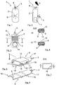
- FIG. 1 and 2 are a plan view and a side view of a magnetic field generator as natural field simulator 1 shown approximately in natural size. From the housing 2 protrudes at the top of a rotary switch 3, which is also used with an eyelet 4 as a hanger, so that the natural field simulator 1 can be worn on a collar on the chest in front of a thymus gland.
- a light exit opening covered by a crystal 5 is arranged behind which a light-emitting diode 5 of an assembly 6 lies ( Fig. 3 ).
- the housing 2 has a through a cap 7 releasably covered opening as a battery compartment through which also the assembly (6) can be inserted and fixed during assembly.
- the assembly 6 consists essentially of an electronic board 8, a magnetic iron core as iron core sheet metal tube 9, a magnetic coil 10 which is wound on the iron core sheet metal tube 9 and a lithium button battery 11.
- the assembly 6 is in the mounted state in the Housing 2 inserted and fills this largely, as indicated by the dashed line as a housing 2.
- the protruding from the housing 2 rotary switch 3 is attached to the electronic board 8.
- Fig. 4a shows a cross section in the region of the iron core sheet metal tube 9 and the magnetic coil 10 with an electronic circuit board 8 which is equipped on both sides with schematically indicated electronic elements 12.
- the electronic board 8 is in Fig. 4a arranged correspondingly in the longitudinal center of the sheet iron tube 9, as described in detail in the enlarged views of Fig. 5 to 7 is shown with two identical sheet metal shell parts 13, 14.
- the electronics board 8 as in Fig. 4b shown only one side is equipped with electronic elements 12, it may be appropriate to make the lower sheet metal shell part flatter and lower the electronics board 8, which may optionally be possible further reduction in volume.
- the iron core sheet metal tube 9 consisting of two sheet metal shell parts 13, 14 is enlarged and shown with further details.
- the (bare) electronic board 8 which is inserted and held between the sheet metal shell parts 13, 14, shown enlarged.
- two mutually offset cams are formed on the electronic board 8 at both longitudinal edges, which lie between the longitudinal edges of the sheet metal shell parts 13, 14, whereby an air gap 16 formed on both sides between the sheet metal shell parts 13, 14 for electrical insulation is, as shown in particular from the cross section along the line BB Fig. 7 is apparent.
- the iron core sheet metal tube 9 of the two sheet metal shell parts 13, 14 is shorter than the electronic circuit board 8, which projects beyond the sheet metal shell parts 13, 14 in the longitudinal direction on both sides with board projections 17, 18. It is attached to the upper board projection 17 of the housing 2 upwardly projecting rotary switch 3. At the lower board projection 18, the light-emitting diode 5 is arranged, which is not covered by the sheet metal shell parts 13, 14 and behind the light exit opening on the housing 2, which is visually appealing by a ground crystal.
Landscapes
- Health & Medical Sciences (AREA)
- Engineering & Computer Science (AREA)
- Biomedical Technology (AREA)
- Nuclear Medicine, Radiotherapy & Molecular Imaging (AREA)
- Radiology & Medical Imaging (AREA)
- Life Sciences & Earth Sciences (AREA)
- Animal Behavior & Ethology (AREA)
- General Health & Medical Sciences (AREA)
- Public Health (AREA)
- Veterinary Medicine (AREA)
- Battery Mounting, Suspending (AREA)
Claims (9)
- Générateur de champ magnétique, en tant que simulateur de champ naturel (1), dans un boîtier (2) pouvant être porté sur le corps et renfermant une bobine magnétique (10) sur un noyau ferromagnétique (9) pour la génération d'un champ, une électronique sur une carte de circuit imprimé électronique (8) pour la génération d'impulsions, et une batterie haute performance (11) pour l'alimentation électrique,
dans lequel le noyau ferromagnétique (9) est réalisé sous la forme d'un corps creux constitué de matériau électriquement conducteur et la bobine magnétique (10) est enroulée sur le corps creux du noyau ferromagnétique (9), caractérisé en ce que la carte de circuit imprimé électronique (8) munie des composants électroniques (12) est au moins partiellement logée dans le corps creux (9) du noyau ferromagnétique. - Générateur de champ magnétique selon la revendication 1, caractérisé en ce que le corps creux du noyau de fer est un tube en tôle de noyau de fer (9), ouvert des deux côtés et ayant une longueur déterminée, dans lequel est inséré une carte de circuit imprimé électronique (8) plus longue présentant des parties saillantes (17, 18) des deux côtés de la carte de circuit imprimé.
- Générateur de champ magnétique selon la revendication 2, caractérisé en ce qu'un commutateur (3), de préférence sous la forme d'un embout de commutateur tournant, pour activer et désactiver le simulateur de champ naturel (1), qui présente en particulier un alésage (4) pour la fixation à un collier, est disposé sur une partie saillante (17) de la carte de circuit imprimé en dépassant d'une ouverture traversante du boîtier (2), et/ou en ce que, sur l'autre partie saillante (18) de la carte de circuit imprimé, est disposée une diode électroluminescente d'indication de fonctionnement (5), qui est située à l'arrière d'une ouverture de boîtier transparente recouverte, de préférence recouverte d'un cristal, en tant qu'ouverture d'émission de lumière, et en ce que ladite partie saillante (18) de la carte de circuit imprimé est réalisée du côté de l'extrémité, notamment de manière concave, le cas échéant avec des ressorts de contact permettant de loger de manière coextensive une batterie bouton (11) en tant que batterie haute performance.
- Générateur de champ magnétique selon l'une des revendications 1 à 3, caractérisé en ce que le corps creux de noyau de fer est réalisé sous la forme d'un tube de tôle de noyau de fer (9) à partir de deux parties de coque en tôle (13, 14) de préférence plates, dont les bords longitudinaux opposés respectifs sont séparés par au moins un interstice isolant (16) s'étendant dans la direction longitudinale du champ magnétique.
- Générateur de champ magnétique selon la revendication 4, caractérisé en ce que la carte de circuit imprimé électronique (8) présente des cames (15) qui s'écartent latéralement en tant que prolongements de la carte de circuit imprimé électronique, qui font respectivement saillie entre les bords longitudinaux de la coque pour réaliser l'interstice (16), et en ce que les bords de la coque présentent respectivement, dans la zone des cames, un contour de maintien des cames (15) situées entre ceux-ci pour la fixation de la carte de circuit imprimé électronique (8), dans lequel les parties de coque (13, 14) sont reliées par l'intermédiaire de la carte de circuit imprimé électronique (9), et y sont notamment soudées.
- Générateur de champ magnétique selon la revendication 4 ou 5, caractérisé en ce que les deux parties de coque en tôle (13, 14) sont des pièces identiques.
- Générateur de champ magnétique selon l'une des revendications 1 à 6, caractérisé en ce que le noyau ferromagnétique, en tant que corps creux (9), forme, avec la carte de circuit imprimé électronique (8) au moins partiellement montée dans celui-ci, un module (6) qui constitue également le corps d'enroulement de l'enroulement magnétique de la bobine magnétique (10).
- Générateur de champ magnétique selon l'une des revendications 1 à 7, caractérisé en ce que la batterie haute performance est une batterie bouton au lithium (11) qui est constituée d'un alliage métallique magnétiquement conducteur et est disposée dans la direction de l'axe magnétique de la bobine magnétique (10).
- Générateur de champ magnétique selon l'une des revendications 1 à 8, caractérisé en ce que le boîtier (2) présente une ouverture recouverte par un couvercle de fermeture (7) amovible, en tant que compartiment pour batterie, et par l'intermédiaire de laquelle le module (6) peut également être inséré et fixé lors du montage.
Applications Claiming Priority (2)
| Application Number | Priority Date | Filing Date | Title |
|---|---|---|---|
| DE102015011092.6A DE102015011092A1 (de) | 2015-08-28 | 2015-08-28 | Magnetfeldgenerator als Naturfeldsimulator |
| PCT/EP2016/001447 WO2017036585A1 (fr) | 2015-08-28 | 2016-08-26 | Générateur de champ magnétique en tant que simulateur de champ naturel |
Publications (2)
| Publication Number | Publication Date |
|---|---|
| EP3341078A1 EP3341078A1 (fr) | 2018-07-04 |
| EP3341078B1 true EP3341078B1 (fr) | 2019-08-21 |
Family
ID=56893920
Family Applications (1)
| Application Number | Title | Priority Date | Filing Date |
|---|---|---|---|
| EP16763195.1A Active EP3341078B1 (fr) | 2015-08-28 | 2016-08-26 | Générateur de champ magnétique en tant que simulateur de champ naturel |
Country Status (4)
| Country | Link |
|---|---|
| EP (1) | EP3341078B1 (fr) |
| DE (1) | DE102015011092A1 (fr) |
| DK (1) | DK3341078T3 (fr) |
| WO (1) | WO2017036585A1 (fr) |
Families Citing this family (3)
| Publication number | Priority date | Publication date | Assignee | Title |
|---|---|---|---|---|
| CN109073413B (zh) | 2016-04-29 | 2021-10-08 | Tdk-迈克纳斯有限责任公司 | 间距测量设备 |
| DE102017010926A1 (de) | 2017-11-24 | 2019-05-29 | Peter Feucht | Magnetfeldgenerator als tragbarer Naturfeldsimulator |
| JP7342127B2 (ja) | 2018-12-18 | 2023-09-11 | パイオミック メディカル アクチェンゲゼルシャフト | 治療装置 |
Family Cites Families (6)
| Publication number | Priority date | Publication date | Assignee | Title |
|---|---|---|---|---|
| JPH03501571A (ja) * | 1987-12-14 | 1991-04-11 | エレクトロマグネティック セラピーズ リミテッド | 治療用磁界発生器 |
| SI9900086A (sl) * | 1999-04-09 | 1999-10-31 | Vili Poznik | Generator pulzirajočega magnetnega polja |
| SE517159C2 (sv) * | 2000-07-07 | 2002-04-23 | Med Tech As | Magnetfältgenerator för en elektromedicinsk behandlingsapparat samt förfarande för framställning därav |
| US7819794B2 (en) * | 2002-10-21 | 2010-10-26 | Becker Paul F | Method and apparatus for the treatment of physical and mental disorders with low frequency, low flux density magnetic fields |
| JP2008131708A (ja) * | 2006-11-20 | 2008-06-05 | Fuji Electric Device Technology Co Ltd | Acアダプタ |
| EP2525872A1 (fr) * | 2010-01-19 | 2012-11-28 | Sergey Vladimirovich Pletnev | Appareil portable d'irradiation électromagnétique combinée locale |
-
2015
- 2015-08-28 DE DE102015011092.6A patent/DE102015011092A1/de not_active Withdrawn
-
2016
- 2016-08-26 WO PCT/EP2016/001447 patent/WO2017036585A1/fr not_active Ceased
- 2016-08-26 DK DK16763195T patent/DK3341078T3/da active
- 2016-08-26 EP EP16763195.1A patent/EP3341078B1/fr active Active
Non-Patent Citations (1)
| Title |
|---|
| None * |
Also Published As
| Publication number | Publication date |
|---|---|
| DK3341078T3 (da) | 2019-11-25 |
| EP3341078A1 (fr) | 2018-07-04 |
| DE102015011092A1 (de) | 2017-03-02 |
| WO2017036585A1 (fr) | 2017-03-09 |
Similar Documents
| Publication | Publication Date | Title |
|---|---|---|
| DE2916350C2 (de) | Thermoelektrische Armbanduhr | |
| DE60204050T2 (de) | Vhf-wellenempfängerantenne, die in einem armband einer tragbaren elektronischen einrichtung untergebracht ist | |
| DE3027048A1 (de) | Elektroakustischer uebertrager fuer hoerhilfsgeraete | |
| EP0483065A1 (fr) | Montre-bracelet | |
| EP3341078A1 (fr) | Générateur de champ magnétique en tant que simulateur de champ naturel | |
| EP0373198A1 (fr) | Soupape magnetique a force de fermeture creee par aimants permanents. | |
| DE69800386T2 (de) | Tafel zum Montieren von Anzeigeelementen | |
| DE2359071A1 (de) | Zeithaltendes geraet | |
| DE102007063170A1 (de) | Induktionsbauteil | |
| DE850771C (de) | Elektrischer Kontakt | |
| DE2135866C3 (de) | Kontaktfederanordnung | |
| DE102009037825A1 (de) | Bedienvorrichtung für ein Elektrogerät | |
| DE871637C (de) | Polarisiertes Elektromagnetsystem | |
| DE2258922B2 (de) | Magnetisch betätigbarer, abgeschlossener Kontakt und Anordnung desselben | |
| DE2556476A1 (de) | Elektrische schaltungseinrichtung fuer eine mit elektrischen oder elektronischen elementen versehene armbanduhr | |
| DE536173C (de) | Amperemeter | |
| EP3713641B1 (fr) | Générateur de champ magnétique en tant que simulateur portable de champ naturel | |
| DE839970C (de) | Zaehlertriebmagnet | |
| DE20019542U1 (de) | In einem Kunststoffgehäuse gekapselter Nährungsschalter mit Abschirmung | |
| EP0683442B1 (fr) | Petite montre électronique | |
| DE10242494A1 (de) | Transponderuhr mit metallischem Gehäuse | |
| DE102006008393B4 (de) | Stromzähler | |
| CH388857A (de) | Antriebselement für elektrisch angetriebene Gangregler | |
| DE3143546A1 (de) | Anklemmbare uhr | |
| AT237084B (de) | Elektromagnetisches Relais |
Legal Events
| Date | Code | Title | Description |
|---|---|---|---|
| STAA | Information on the status of an ep patent application or granted ep patent |
Free format text: STATUS: THE INTERNATIONAL PUBLICATION HAS BEEN MADE |
|
| PUAI | Public reference made under article 153(3) epc to a published international application that has entered the european phase |
Free format text: ORIGINAL CODE: 0009012 |
|
| STAA | Information on the status of an ep patent application or granted ep patent |
Free format text: STATUS: REQUEST FOR EXAMINATION WAS MADE |
|
| 17P | Request for examination filed |
Effective date: 20180312 |
|
| AK | Designated contracting states |
Kind code of ref document: A1 Designated state(s): AL AT BE BG CH CY CZ DE DK EE ES FI FR GB GR HR HU IE IS IT LI LT LU LV MC MK MT NL NO PL PT RO RS SE SI SK SM TR |
|
| AX | Request for extension of the european patent |
Extension state: BA ME |
|
| DAV | Request for validation of the european patent (deleted) | ||
| DAX | Request for extension of the european patent (deleted) | ||
| GRAP | Despatch of communication of intention to grant a patent |
Free format text: ORIGINAL CODE: EPIDOSNIGR1 |
|
| STAA | Information on the status of an ep patent application or granted ep patent |
Free format text: STATUS: GRANT OF PATENT IS INTENDED |
|
| INTG | Intention to grant announced |
Effective date: 20190306 |
|
| GRAS | Grant fee paid |
Free format text: ORIGINAL CODE: EPIDOSNIGR3 |
|
| GRAA | (expected) grant |
Free format text: ORIGINAL CODE: 0009210 |
|
| STAA | Information on the status of an ep patent application or granted ep patent |
Free format text: STATUS: THE PATENT HAS BEEN GRANTED |
|
| AK | Designated contracting states |
Kind code of ref document: B1 Designated state(s): AL AT BE BG CH CY CZ DE DK EE ES FI FR GB GR HR HU IE IS IT LI LT LU LV MC MK MT NL NO PL PT RO RS SE SI SK SM TR |
|
| REG | Reference to a national code |
Ref country code: GB Ref legal event code: FG4D Free format text: NOT ENGLISH |
|
| REG | Reference to a national code |
Ref country code: CH Ref legal event code: EP |
|
| REG | Reference to a national code |
Ref country code: DE Ref legal event code: R096 Ref document number: 502016006222 Country of ref document: DE |
|
| REG | Reference to a national code |
Ref country code: AT Ref legal event code: REF Ref document number: 1169029 Country of ref document: AT Kind code of ref document: T Effective date: 20190915 |
|
| REG | Reference to a national code |
Ref country code: IE Ref legal event code: FG4D Free format text: LANGUAGE OF EP DOCUMENT: GERMAN |
|
| REG | Reference to a national code |
Ref country code: CH Ref legal event code: NV Representative=s name: ABACUS PATENTANWAELTE KLOCKE SPAETH BARTH, CH |
|
| REG | Reference to a national code |
Ref country code: DK Ref legal event code: T3 Effective date: 20191121 |
|
| REG | Reference to a national code |
Ref country code: NL Ref legal event code: FP |
|
| REG | Reference to a national code |
Ref country code: LT Ref legal event code: MG4D |
|
| PG25 | Lapsed in a contracting state [announced via postgrant information from national office to epo] |
Ref country code: FI Free format text: LAPSE BECAUSE OF FAILURE TO SUBMIT A TRANSLATION OF THE DESCRIPTION OR TO PAY THE FEE WITHIN THE PRESCRIBED TIME-LIMIT Effective date: 20190821 Ref country code: SE Free format text: LAPSE BECAUSE OF FAILURE TO SUBMIT A TRANSLATION OF THE DESCRIPTION OR TO PAY THE FEE WITHIN THE PRESCRIBED TIME-LIMIT Effective date: 20190821 Ref country code: HR Free format text: LAPSE BECAUSE OF FAILURE TO SUBMIT A TRANSLATION OF THE DESCRIPTION OR TO PAY THE FEE WITHIN THE PRESCRIBED TIME-LIMIT Effective date: 20190821 Ref country code: LT Free format text: LAPSE BECAUSE OF FAILURE TO SUBMIT A TRANSLATION OF THE DESCRIPTION OR TO PAY THE FEE WITHIN THE PRESCRIBED TIME-LIMIT Effective date: 20190821 Ref country code: BG Free format text: LAPSE BECAUSE OF FAILURE TO SUBMIT A TRANSLATION OF THE DESCRIPTION OR TO PAY THE FEE WITHIN THE PRESCRIBED TIME-LIMIT Effective date: 20191121 Ref country code: NO Free format text: LAPSE BECAUSE OF FAILURE TO SUBMIT A TRANSLATION OF THE DESCRIPTION OR TO PAY THE FEE WITHIN THE PRESCRIBED TIME-LIMIT Effective date: 20191121 Ref country code: PT Free format text: LAPSE BECAUSE OF FAILURE TO SUBMIT A TRANSLATION OF THE DESCRIPTION OR TO PAY THE FEE WITHIN THE PRESCRIBED TIME-LIMIT Effective date: 20191223 |
|
| PG25 | Lapsed in a contracting state [announced via postgrant information from national office to epo] |
Ref country code: LV Free format text: LAPSE BECAUSE OF FAILURE TO SUBMIT A TRANSLATION OF THE DESCRIPTION OR TO PAY THE FEE WITHIN THE PRESCRIBED TIME-LIMIT Effective date: 20190821 Ref country code: RS Free format text: LAPSE BECAUSE OF FAILURE TO SUBMIT A TRANSLATION OF THE DESCRIPTION OR TO PAY THE FEE WITHIN THE PRESCRIBED TIME-LIMIT Effective date: 20190821 Ref country code: IS Free format text: LAPSE BECAUSE OF FAILURE TO SUBMIT A TRANSLATION OF THE DESCRIPTION OR TO PAY THE FEE WITHIN THE PRESCRIBED TIME-LIMIT Effective date: 20191221 Ref country code: GR Free format text: LAPSE BECAUSE OF FAILURE TO SUBMIT A TRANSLATION OF THE DESCRIPTION OR TO PAY THE FEE WITHIN THE PRESCRIBED TIME-LIMIT Effective date: 20191122 Ref country code: ES Free format text: LAPSE BECAUSE OF FAILURE TO SUBMIT A TRANSLATION OF THE DESCRIPTION OR TO PAY THE FEE WITHIN THE PRESCRIBED TIME-LIMIT Effective date: 20190821 Ref country code: AL Free format text: LAPSE BECAUSE OF FAILURE TO SUBMIT A TRANSLATION OF THE DESCRIPTION OR TO PAY THE FEE WITHIN THE PRESCRIBED TIME-LIMIT Effective date: 20190821 |
|
| PG25 | Lapsed in a contracting state [announced via postgrant information from national office to epo] |
Ref country code: TR Free format text: LAPSE BECAUSE OF FAILURE TO SUBMIT A TRANSLATION OF THE DESCRIPTION OR TO PAY THE FEE WITHIN THE PRESCRIBED TIME-LIMIT Effective date: 20190821 |
|
| PG25 | Lapsed in a contracting state [announced via postgrant information from national office to epo] |
Ref country code: EE Free format text: LAPSE BECAUSE OF FAILURE TO SUBMIT A TRANSLATION OF THE DESCRIPTION OR TO PAY THE FEE WITHIN THE PRESCRIBED TIME-LIMIT Effective date: 20190821 Ref country code: PL Free format text: LAPSE BECAUSE OF FAILURE TO SUBMIT A TRANSLATION OF THE DESCRIPTION OR TO PAY THE FEE WITHIN THE PRESCRIBED TIME-LIMIT Effective date: 20190821 Ref country code: IT Free format text: LAPSE BECAUSE OF FAILURE TO SUBMIT A TRANSLATION OF THE DESCRIPTION OR TO PAY THE FEE WITHIN THE PRESCRIBED TIME-LIMIT Effective date: 20190821 Ref country code: RO Free format text: LAPSE BECAUSE OF FAILURE TO SUBMIT A TRANSLATION OF THE DESCRIPTION OR TO PAY THE FEE WITHIN THE PRESCRIBED TIME-LIMIT Effective date: 20190821 |
|
| PG25 | Lapsed in a contracting state [announced via postgrant information from national office to epo] |
Ref country code: LU Free format text: LAPSE BECAUSE OF NON-PAYMENT OF DUE FEES Effective date: 20190826 Ref country code: SM Free format text: LAPSE BECAUSE OF FAILURE TO SUBMIT A TRANSLATION OF THE DESCRIPTION OR TO PAY THE FEE WITHIN THE PRESCRIBED TIME-LIMIT Effective date: 20190821 Ref country code: SK Free format text: LAPSE BECAUSE OF FAILURE TO SUBMIT A TRANSLATION OF THE DESCRIPTION OR TO PAY THE FEE WITHIN THE PRESCRIBED TIME-LIMIT Effective date: 20190821 Ref country code: CZ Free format text: LAPSE BECAUSE OF FAILURE TO SUBMIT A TRANSLATION OF THE DESCRIPTION OR TO PAY THE FEE WITHIN THE PRESCRIBED TIME-LIMIT Effective date: 20190821 Ref country code: MC Free format text: LAPSE BECAUSE OF FAILURE TO SUBMIT A TRANSLATION OF THE DESCRIPTION OR TO PAY THE FEE WITHIN THE PRESCRIBED TIME-LIMIT Effective date: 20190821 Ref country code: IS Free format text: LAPSE BECAUSE OF FAILURE TO SUBMIT A TRANSLATION OF THE DESCRIPTION OR TO PAY THE FEE WITHIN THE PRESCRIBED TIME-LIMIT Effective date: 20200224 |
|
| REG | Reference to a national code |
Ref country code: DE Ref legal event code: R097 Ref document number: 502016006222 Country of ref document: DE |
|
| PLBE | No opposition filed within time limit |
Free format text: ORIGINAL CODE: 0009261 |
|
| STAA | Information on the status of an ep patent application or granted ep patent |
Free format text: STATUS: NO OPPOSITION FILED WITHIN TIME LIMIT |
|
| PG2D | Information on lapse in contracting state deleted |
Ref country code: IS |
|
| PG25 | Lapsed in a contracting state [announced via postgrant information from national office to epo] |
Ref country code: IE Free format text: LAPSE BECAUSE OF NON-PAYMENT OF DUE FEES Effective date: 20190826 |
|
| 26N | No opposition filed |
Effective date: 20200603 |
|
| PG25 | Lapsed in a contracting state [announced via postgrant information from national office to epo] |
Ref country code: SI Free format text: LAPSE BECAUSE OF FAILURE TO SUBMIT A TRANSLATION OF THE DESCRIPTION OR TO PAY THE FEE WITHIN THE PRESCRIBED TIME-LIMIT Effective date: 20190821 |
|
| PG25 | Lapsed in a contracting state [announced via postgrant information from national office to epo] |
Ref country code: FR Free format text: LAPSE BECAUSE OF NON-PAYMENT OF DUE FEES Effective date: 20191021 |
|
| PG25 | Lapsed in a contracting state [announced via postgrant information from national office to epo] |
Ref country code: CY Free format text: LAPSE BECAUSE OF FAILURE TO SUBMIT A TRANSLATION OF THE DESCRIPTION OR TO PAY THE FEE WITHIN THE PRESCRIBED TIME-LIMIT Effective date: 20190821 |
|
| PG25 | Lapsed in a contracting state [announced via postgrant information from national office to epo] |
Ref country code: MT Free format text: LAPSE BECAUSE OF FAILURE TO SUBMIT A TRANSLATION OF THE DESCRIPTION OR TO PAY THE FEE WITHIN THE PRESCRIBED TIME-LIMIT Effective date: 20190821 Ref country code: HU Free format text: LAPSE BECAUSE OF FAILURE TO SUBMIT A TRANSLATION OF THE DESCRIPTION OR TO PAY THE FEE WITHIN THE PRESCRIBED TIME-LIMIT; INVALID AB INITIO Effective date: 20160826 |
|
| PG25 | Lapsed in a contracting state [announced via postgrant information from national office to epo] |
Ref country code: MK Free format text: LAPSE BECAUSE OF FAILURE TO SUBMIT A TRANSLATION OF THE DESCRIPTION OR TO PAY THE FEE WITHIN THE PRESCRIBED TIME-LIMIT Effective date: 20190821 |
|
| P01 | Opt-out of the competence of the unified patent court (upc) registered |
Effective date: 20230530 |
|
| PGFP | Annual fee paid to national office [announced via postgrant information from national office to epo] |
Ref country code: GB Payment date: 20230810 Year of fee payment: 8 |
|
| PGFP | Annual fee paid to national office [announced via postgrant information from national office to epo] |
Ref country code: DK Payment date: 20230818 Year of fee payment: 8 Ref country code: BE Payment date: 20230830 Year of fee payment: 8 |
|
| REG | Reference to a national code |
Ref country code: DK Ref legal event code: EBP Effective date: 20240831 |
|
| GBPC | Gb: european patent ceased through non-payment of renewal fee |
Effective date: 20240826 |
|
| REG | Reference to a national code |
Ref country code: BE Ref legal event code: MM Effective date: 20240831 |
|
| PG25 | Lapsed in a contracting state [announced via postgrant information from national office to epo] |
Ref country code: GB Free format text: LAPSE BECAUSE OF NON-PAYMENT OF DUE FEES Effective date: 20240826 Ref country code: DK Free format text: LAPSE BECAUSE OF NON-PAYMENT OF DUE FEES Effective date: 20240831 |
|
| PG25 | Lapsed in a contracting state [announced via postgrant information from national office to epo] |
Ref country code: BE Free format text: LAPSE BECAUSE OF NON-PAYMENT OF DUE FEES Effective date: 20240831 |
|
| PGFP | Annual fee paid to national office [announced via postgrant information from national office to epo] |
Ref country code: NL Payment date: 20250826 Year of fee payment: 10 |
|
| PGFP | Annual fee paid to national office [announced via postgrant information from national office to epo] |
Ref country code: DE Payment date: 20250827 Year of fee payment: 10 |
|
| PGFP | Annual fee paid to national office [announced via postgrant information from national office to epo] |
Ref country code: AT Payment date: 20250825 Year of fee payment: 10 |
|
| PGFP | Annual fee paid to national office [announced via postgrant information from national office to epo] |
Ref country code: CH Payment date: 20250901 Year of fee payment: 10 |