EP3341085B1 - Dispositif de navette - Google Patents
Dispositif de navette Download PDFInfo
- Publication number
- EP3341085B1 EP3341085B1 EP16840403.6A EP16840403A EP3341085B1 EP 3341085 B1 EP3341085 B1 EP 3341085B1 EP 16840403 A EP16840403 A EP 16840403A EP 3341085 B1 EP3341085 B1 EP 3341085B1
- Authority
- EP
- European Patent Office
- Prior art keywords
- shuttle device
- shuttle
- mouth
- relative
- unlocked
- Prior art date
- Legal status (The legal status is an assumption and is not a legal conclusion. Google has not performed a legal analysis and makes no representation as to the accuracy of the status listed.)
- Not-in-force
Links
- 230000007246 mechanism Effects 0.000 claims description 8
- 230000003068 static effect Effects 0.000 description 12
- 238000004519 manufacturing process Methods 0.000 description 4
- 208000027418 Wounds and injury Diseases 0.000 description 3
- 230000006378 damage Effects 0.000 description 3
- 208000014674 injury Diseases 0.000 description 3
- 238000010276 construction Methods 0.000 description 2
- 230000003993 interaction Effects 0.000 description 2
- 230000035939 shock Effects 0.000 description 2
- 239000006096 absorbing agent Substances 0.000 description 1
- 238000010521 absorption reaction Methods 0.000 description 1
- 230000002950 deficient Effects 0.000 description 1
- 230000001419 dependent effect Effects 0.000 description 1
- 238000006073 displacement reaction Methods 0.000 description 1
- 238000003780 insertion Methods 0.000 description 1
- 230000037431 insertion Effects 0.000 description 1
- 238000000034 method Methods 0.000 description 1
- 230000000007 visual effect Effects 0.000 description 1
Images

Classifications
-
- A—HUMAN NECESSITIES
- A62—LIFE-SAVING; FIRE-FIGHTING
- A62B—DEVICES, APPARATUS OR METHODS FOR LIFE-SAVING
- A62B35/00—Safety belts or body harnesses; Similar equipment for limiting displacement of the human body, especially in case of sudden changes of motion
- A62B35/0081—Equipment which can travel along the length of a lifeline, e.g. travelers
-
- A—HUMAN NECESSITIES
- A62—LIFE-SAVING; FIRE-FIGHTING
- A62B—DEVICES, APPARATUS OR METHODS FOR LIFE-SAVING
- A62B35/00—Safety belts or body harnesses; Similar equipment for limiting displacement of the human body, especially in case of sudden changes of motion
- A62B35/0006—Harnesses; Accessories therefor
- A62B35/0025—Details and accessories
- A62B35/0037—Attachments for lifelines and lanyards
-
- A—HUMAN NECESSITIES
- A62—LIFE-SAVING; FIRE-FIGHTING
- A62B—DEVICES, APPARATUS OR METHODS FOR LIFE-SAVING
- A62B35/00—Safety belts or body harnesses; Similar equipment for limiting displacement of the human body, especially in case of sudden changes of motion
- A62B35/0043—Lifelines, lanyards, and anchors therefore
- A62B35/0056—Horizontal lifelines
-
- A—HUMAN NECESSITIES
- A62—LIFE-SAVING; FIRE-FIGHTING
- A62B—DEVICES, APPARATUS OR METHODS FOR LIFE-SAVING
- A62B35/00—Safety belts or body harnesses; Similar equipment for limiting displacement of the human body, especially in case of sudden changes of motion
- A62B35/0043—Lifelines, lanyards, and anchors therefore
- A62B35/0075—Details of ropes or similar equipment, e.g. between the secured person and the lifeline or anchor
-
- A—HUMAN NECESSITIES
- A62—LIFE-SAVING; FIRE-FIGHTING
- A62B—DEVICES, APPARATUS OR METHODS FOR LIFE-SAVING
- A62B35/00—Safety belts or body harnesses; Similar equipment for limiting displacement of the human body, especially in case of sudden changes of motion
- A62B35/0081—Equipment which can travel along the length of a lifeline, e.g. travelers
- A62B35/0087—Arrangements for bypassing lifeline supports without lanyard disconnection
-
- E—FIXED CONSTRUCTIONS
- E04—BUILDING
- E04G—SCAFFOLDING; FORMS; SHUTTERING; BUILDING IMPLEMENTS OR AIDS, OR THEIR USE; HANDLING BUILDING MATERIALS ON THE SITE; REPAIRING, BREAKING-UP OR OTHER WORK ON EXISTING BUILDINGS
- E04G21/00—Preparing, conveying, or working-up building materials or building elements in situ; Other devices or measures for constructional work
- E04G21/32—Safety or protective measures for persons during the construction of buildings
- E04G21/3261—Safety-nets; Safety mattresses; Arrangements on buildings for connecting safety-lines
-
- E—FIXED CONSTRUCTIONS
- E04—BUILDING
- E04G—SCAFFOLDING; FORMS; SHUTTERING; BUILDING IMPLEMENTS OR AIDS, OR THEIR USE; HANDLING BUILDING MATERIALS ON THE SITE; REPAIRING, BREAKING-UP OR OTHER WORK ON EXISTING BUILDINGS
- E04G21/00—Preparing, conveying, or working-up building materials or building elements in situ; Other devices or measures for constructional work
- E04G21/32—Safety or protective measures for persons during the construction of buildings
- E04G21/3261—Safety-nets; Safety mattresses; Arrangements on buildings for connecting safety-lines
- E04G21/3276—Arrangements on buildings for connecting safety-lines
- E04G21/329—Arrangements on buildings for connecting safety-lines with measures for dampening the fall
-
- E—FIXED CONSTRUCTIONS
- E04—BUILDING
- E04G—SCAFFOLDING; FORMS; SHUTTERING; BUILDING IMPLEMENTS OR AIDS, OR THEIR USE; HANDLING BUILDING MATERIALS ON THE SITE; REPAIRING, BREAKING-UP OR OTHER WORK ON EXISTING BUILDINGS
- E04G21/00—Preparing, conveying, or working-up building materials or building elements in situ; Other devices or measures for constructional work
- E04G21/32—Safety or protective measures for persons during the construction of buildings
- E04G21/3261—Safety-nets; Safety mattresses; Arrangements on buildings for connecting safety-lines
- E04G21/3295—Guide tracks for safety lines
Definitions
- the invention described herein relates to a shuttle device.
- the invention is directed to a shuttle device for connecting a user to a height safety or fall arrest system.
- a height safety line system can be used on a roof to protect a worker from serious injury in the event of a falling incident.
- the safety line system typically includes a number of anchors secured to the roof, and a cable secured to the anchors.
- a lanyard attached to a harness worn by a worker can be linked to the cable via a shuttle device.
- a shock absorber device is used with the lanyard to facilitate shock absorption in the event of a fall.
- the static line system therefore provides a means to prevent the worker from hitting the ground in the event of a fall.
- the shuttle device is connectable to and movable along the cable of the safety line system.
- the shuttle device thereby connects the worker to the safety line system and provides the worker with sufficient mobility to move around the worksite.
- Current shuttle devices typically involve internal mechanisms which allow the shuttle to lock and unlock for attachment to and detachment from the cable.
- some shuttle devices can be costly and complex to manufacture, which can often result in errors in the manufacturing process. Defective shuttle devices can undesirably cause malfunctioning of the height safety system and thereby endanger workers.
- Some shuttle devices can also be complex to use, which can undesirably lead to operational errors.
- GB 2388148 discloses a prior art shuttle device which can be removably attached to a cable (although the device is referred to as a "safety anchor device" in GB 2388148 .
- the device includes a first member and a second member, each having a body member having a generally C-shaped cross section and a longitudinal axis, wherein each body member defines a recess and an opening through which the recess is accessible, each opening having a first side and a second side; wherein said second member is received in the recess of the first member, the second member being slidable relative to the first member to facilitate movement of the device between a locked condition in which the cable is held within the shuttle device and an unlocked condition in which the cable can be removed from the shuttle device, wherein in the locked condition the second member and a side of an inner wall of the first member define a mouth which is narrower than the cable.
- Embodiments of the present invention provide an improved shuttle device for connecting a user to a height safety system, which overcomes or ameliorates one or more of the disadvantages or problems described above, or which at least provides the consumer with a useful choice.
- a shuttle device for a height safety system as claimed in claim 1.
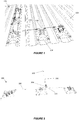
- a static line height safety system 100 is shown in Figure 1 .
- the static line system 100 is secured to an elevated worksite, such as a roof 102.
- the static line system 100 includes a plurality of anchors 104 for mounting to the roof 102 and a cable 106 connecting the anchors 104.
- the cable 106 is attached to each anchor 104 via a cable attachment portion 108.
- the cable attachment portion 108 typically includes a sleeve for receiving a portion of the cable 106 therethrough.
- a worker 200 (not shown) is attached to the static line system 100 via a lanyard 202, a carabiner or quicklink 204 and a shuttle device 300.
- the shuttle device 300 is secured to the cable 106.
- the device 300 is movable along the cable 106, and is capable of passing over the cable attachment portions 108 so as to be movable along the cable 106 from end to end.
- the shuttle device 300 thereby connects the worker 200 to the static line system 100 and allows the worker 200 to safely move about the elevated worksite within the confines of the static line system 100. In the event of a fall, the worker 200 will remain safely attached to the static line system 100 via the shuttle device 300, thereby preventing the worker 200 from serious injury.
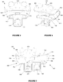
- the shuttle device 300 includes a first member 400 and a second member 500.
- the first member 400 has an elongate body 402 having a generally C-shaped cross section.
- the body 402 has an inner wall 404 defining a recess 406.
- the inner wall 404 terminates at first and second sides 410, 412 of the recess 406 to define an opening 408 of the first member 400.
- the second member 500 also has an elongate body 502 having a generally C-shaped cross section.
- the body 502 also has an inner wall 504 defining a recess 506.
- the inner wall 504 terminates at first and second sides 510, 512 of the recess 506 to define an opening 508 of the second member 500.
- the first side 410 of the first member 400 and the second side 512 of the second member 500 form a mouth (or second opening) 302.
- the mouth 302 is narrower than the opening 408 of the first member 400, as well as the opening 508 of the second member 500.
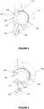
- the shuttle device 300 is movable between a locked condition (see Figures 3 and 4 ) in which the shuttle device 300 is securely attached to the cable 106 of the static line system 100, and an unlocked condition (see Figures 5 and 6 ) in which the shuttle device is attachable to, or removable from, the cable 106 of the static line system 100.
- the second member 500 is slidable relative to the first member 400 so as to move the shuttle device 300 between its locked and unlocked conditions.
- the second member 500 is configured to linearly translate and rotate relative to the first member 400 to vary the size of the mouth 302 to thereby move the shuttle device 300 between locked and unlocked conditions. This will be explained in further detail below.
- the shuttle device 300 further includes a guiding mechanism 304 to guide the relative movement between the first and second members 400, 500.
- the first member 400 includes a guide arm 414 and the second member 500 includes a generally C-shaped guide slot 514.
- the guide arm 414 moves along the generally C-shaped defined path of the guide slot 514 to guide the movement of the second member 500 relative to the first member 400.
- the C-shaped guide slot 514 includes three portions - a first rotation portion 516 in which movement of the guide arm 414 therein causes rotation of the second member 500 about its longitudinal axis relative to the first member 400; a second translation portion 518 in which movement of the guide arm 414 therein causes lateral translation of the second member 500 relative to the first member 400; and a third rotation portion 520 in which movement of the guide arm 414 therein causes rotation of the second member 500 about its longitudinal axis relative to the first member 400 (see Figure 7 ).
- the guide arm 414 When the shuttle device 300 is in the locked condition, the guide arm 414 is located midway in the second translation portion 518.
- a pulling force in a longitudinal direction of the body 502 causes the second member 500 to laterally translate relative to the first member 400 and the guide arm 414 to move along the second translation portion 518 of the guide slot 514 towards either rotation portion 516, 514.
- the second member 500 is rotated about its longitudinal axis relative to the first member 400 until the guide arm 414 reaches an end of the rotation portion 516, 514 ( Figures 6, 7 ).
- the rotation of the second member 500 relative to the first member 400 moves the second side 512 of the opening 508 further away from the first side 410 of the opening 408 of the first member 400, thereby widening the mouth 302 to allow insertion or removal of a height safety system 100 cable 106.
- the guiding mechanism 304 therefore allows the first and second members 400, 500 to move relative to one another according to a defined path.
- the guiding mechanism 304 also prevents the two members 400, 500 from becoming inadvertently separated.
- the shuttle device 300 is capable of carrying out the desired function if the two members 400, 500 were separable.
- the first member 400 includes an internal stepped portion 416 for interaction with an external stepped portion 516 of the second member 500.
- Each stepped portion 416, 516 includes a projection 418, 518.
- the projections 418, 518 abut one another so as to facilitate holding the second member 500 in the correct position relative to the first member 400.
- the projections 418, 518 are disposed adjacent one another (see Figure 6 ) to further facilitate holding the second member 500 in the correct position relative to the first member 400.
- Figure 8 is a side view of the shuttle device 300 in the locked condition.
- the internal projection 418 of the first member 400 abuts the external projection 518 of the second member 500.
- the second side 512 of the second member 500 is positioned relatively close to the first side 410 of the first member 400 such that the mouth 302 of the shuttle device 300 is locked in its narrowed condition.
- the size of the mouth 302 when the shuttle device 300 is locked is configured such that a cable 106 of the height safety system 100 cannot pass through it.
- the recess 506 and the mouth 302 are suitably sized to allow the device 300 to bypass the anchors 104 and cable attachment portions 108.
- Figure 9 is a side view of the shuttle device 300 in an unlocked condition.
- the external projection 518 of the second member 500 is positioned adjacent the internal projection 418 of the first member 400 (hidden).
- the second side 512 of the second member 500 is positioned further away from the first side 410 of the first member 400 such that the mouth 302 of the shuttle device 300 is widened.
- the size of the mouth 302 when the shuttle device 300 is unlocked is configured such that a cable 106 of the height safety system 100 can pass through it.
- the recess 506 and the mouth 302 is suitably sized to allow the cable 106 to pass through it so that the shuttle device 300 can be attached to or removed from the height safety system 100.
- the shuttle device 300 has two unlocked conditions.
- the second member 500 can be moved laterally relative to the first member 400 in either direction to arrive at the unlocked condition. For instance, with reference to Figure 6 , the second member 500 is moved towards the right side of the first member 400. The second member 500 can also be moved towards the left side of the first member 400 to arrive at the unlocked condition.
- each of the first and second members 400, 500 includes a respective attachment portion 422, 522.
- Each attachment portion 422, 522 defines an aperture 424, 524 for attaching a carabiner 204 therethrough.
- the apertures 424, 524 are aligned as shown in Figure 3 to receive a carabiner 204 therethrough ( Figures 3, 4 and 8 ).
- the carabiner 204 When the carabiner 204 is secured through the apertures 424, 524, the carabiner 204 ensures that the two members 400, 500 cannot become dislodged and inadvertently moved to unlock the shuttle device 300 during use.
- the operation of the attachment portions 422, 522 together with the carabiner 204 advantageously provides operational security to ensure safe operation of the shuttle device 300.
- the attachment portions 422, 522 move out of alignment so as to allow rotation of the second member 500 about its longitudinal axis relative to the first member 400 ( Figure 6 and 9 ).
- the first member 400 further includes a weighted portion 424 for biasing the shuttle device 300 in a desired position during operation.
- the weighted portion is shaped like a frog's head for visual appeal.
- the weighted portion 424 can take any suitable shape and form.
- the weighted portion 424 is provided on a side of the first member 400 opposite the attachment portion 422 such that in the locked condition during use, the weighted portion 424 ensures that the mouth 302 typically faces downwardly so as to allow the shuttle device 300 to easily bypass anchors 104 of the height safety system 100.
- a worker 200 can secure himself/herself to a height safety system 100 by using a shuttle device 300 as described herein.
- the shuttle device 300 is moved from a locked to an unlocked condition by sliding the second member 500 relative to the first member 400.
- the second member 500 can be moved in either lateral direction relative to the first member 400.
- the second member 500 translates laterally relative to the first member 400 so that guide arm 414 moves from a central location in the guide slot 514 to one side of the translation portion 516 of the guide slot.
- the second member 400 is rotated about its longitudinal axis relative to first member 500 so that the guide arm 414 moves from one end of a rotation portion 414, 514 to an opposite end ( Figure 7 ).
- the projections 418, 518 move from an abutting position in the locked condition ( Figure 8 ) to a side-by-side position in the unlocked condition ( Figure 6 , 9 ).
- the size of the mouth 302 is enlarged as the second side 512 is moved further away from the first side 410 ( Figure 9 ) to allow the cable 106 of the height safety system 100 to pass through.
- the shuttle device 300 can be locked by reversing the relative rotation and translation movement described above. Once in the locked condition, the second side 512 is moved closer to the first side 410 so as to reduce the side of mouth 302 to prevent the cable 106 from passing through the mouth 302 ( Figure 8 ).
- the attachment portions 522, 422 and respective apertures 424, 524 become aligned ( Figures 3, 4 , 8 ).
- the worker 200 can then attach a carabiner 204 through the apertures 424, 524.
- the carabiner 204 is attached to a lanyard 202 which can be tied or otherwise connected via a connecting device to a harness (not shown) worn by the worker 200.
- the carabiner 204 attached through the apertures 424, 524 ensures that the shuttle device 300 remains in the locked condition until the shuttle device 300 is unlocked.
- the carabiner 204 is simply removed from the apertures 424, 524.
- the shuttle device 300 can also optionally be removed from the system 100 by unlocking the device 300 in the manner previously described.
- the simple construction of the shuttle device 300 makes the device 300 cost effective and simple to manufacture.
- the operating simplicity also avoids errors in the manufacturing and assembly process.
- the simple operation of the device 300 reduces the risk of misuse.
- the first and second members 400, 500 can be moved between a locked and unlocked condition by lateral translation alone.
- the two members 400, 500 may be separable to unlock and combined to lock.
- the cable 106 may be passed through the opening 508 of the second member 500.
- the second member 500 can be inserted in the recess 406 of the first member 400 by lateral translation such that the first member 400 covers a portion of the opening 508 to thereby create a smaller mouth 302 to prevent the cable 106 from escaping the recess 406.
- no relative rotation between the first and second members 400, 500 is required.
Landscapes
- Engineering & Computer Science (AREA)
- Architecture (AREA)
- Health & Medical Sciences (AREA)
- General Health & Medical Sciences (AREA)
- Business, Economics & Management (AREA)
- Emergency Management (AREA)
- Mechanical Engineering (AREA)
- Civil Engineering (AREA)
- Structural Engineering (AREA)
- Emergency Lowering Means (AREA)
- Jib Cranes (AREA)
- Auxiliary Devices For Machine Tools (AREA)
- Mechanical Control Devices (AREA)
- Seats For Vehicles (AREA)
Claims (12)
- Dispositif de navette (300) pour un système de sécurité en hauteur (100) comportant un câble (106), le dispositif (300) comportant
un premier élément (400) et un second élément (500), chacun ayant un élément de corps (402, 502) ayant une section transversale généralement en forme de C et un axe longitudinal, dans lequel chaque élément de corps (402, 502) définit un évidement (406, 506) et une ouverture (408, 508) à travers laquelle l'évidement (406, 506) est accessible, chaque ouverture (406, 506) ayant un premier côté (410, 510) et un second côté (412, 512) ;
dans lequel ledit second élément (500) est reçu dans l'évidement (406) du premier élément (400), le second élément (500) pouvant coulisser par rapport au premier élément (400) pour faciliter le mouvement du dispositif (300) entre un état verrouillé pour empêcher le câble (106) de passer par une embouchure (302) du dispositif de navette (300) et un état déverrouillé dans lequel le câble (106) peut passer par l'embouchure (302) du dispositif de navette (300),
dans lequel, à l'état verrouillé, l'embouchure (302) est définie par le second élément (500) et le premier côté (410) d'une paroi intérieure (404) du premier élément (400), état verrouillé dans lequel ladite embouchure (302) est plus petite que l'ouverture du premier élément ;
le second élément (500) peut coulisser par rapport au premier élément (400) dans une première direction pour faciliter le mouvement du dispositif de navette (300) de l'état verrouillé à un premier état déverrouillé ;
caractérisé en ce que le second élément (500) peut coulisser par rapport au premier élément (400) dans une seconde direction opposée à la première direction pour faciliter le déplacement du dispositif de navette (300) de l'état verrouillé à un second état déverrouillé ;
le second élément (500) se déplace et tourne autour de son axe longitudinal de sorte que le second côté (512) du second élément (500) est éloigné du premier côté (410) du premier élément (400) pour élargir ainsi l'embouchure (302) de manière à passer de l'état verrouillé à l'un desdits premier ou second états déverrouillés, et dans lequel
le second élément (500) tourne autour de son axe longitudinal et se déplace par rapport au premier élément (400) de sorte que le second côté (512) du second élément (500) est déplacé plus près du premier côté (410) du premier élément (400) pour rétrécir ainsi l'embouchure (302) de manière à passer de l'un desdits premier ou second états déverrouillés à l'état verrouillé. - Dispositif de navette selon la revendication 1, dans lequel le second élément (500) peut tourner par rapport au premier élément (400) pour faciliter le mouvement du dispositif (300) entre des états verrouillé et déverrouillé.
- Dispositif de navette selon l'une quelconque des revendications précédentes, dans lequel le second élément (500) est conçu pour se déplacer et tourner par rapport au premier élément (400) pour déplacer le dispositif (300) entre des états verrouillé et déverrouillé.
- Dispositif de navette selon l'une quelconque des revendications précédentes, comportant en outre un mécanisme de guidage (304) pour guider le mouvement relatif entre les premier et second éléments (400, 500).
- Dispositif de navette selon la revendication 4, dans lequel le premier élément (400) comporte un bras de guidage (414) pour se déplacer à l'intérieur d'une fente de guidage (514) du second élément (500), le bras de guidage (414) et la fente de guidage (514) formant le mécanisme de guidage (304).
- Dispositif de navette selon la revendication 5, dans lequel la fente de guidage (514) est généralement en forme de C de manière à guider le second élément (500) à travers une combinaison de mouvement de rotation et de déplacement par rapport au premier élément (400).
- Dispositif de navette selon la revendication 4, dans lequel le mécanisme de guidage (304) comporte en outre des parties étagées opposées (416, 516) pour guider le mouvement relatif entre les premier et second éléments (400, 500).
- Dispositif de navette selon la revendication 7, dans lequel le premier élément (400) comporte une première partie en gradins (416) pour une mise en prise avec une seconde partie en gradins (516) du second élément (500).
- Dispositif de navette selon la revendication 8, dans lequel chaque partie en gradins (416, 516) comporte une saillie (418, 518), et dans lequel
à l'état verrouillé, les saillies (418, 518) de chaque partie en gradins (416, 516) viennent en butée l'une contre l'autre, et
dans un état déverrouillé, les saillies (418, 518) sont disposées les unes à côté des autres. - Dispositif de navette selon l'une quelconque des revendications précédentes, dans lequel chacun des premier et second éléments (400, 500) comporte une partie de fixation (422, 522) pour fixer un dispositif de connexion tel qu'un mousqueton (204) ou un dispositif de liaison rapide à celle-ci.
- Dispositif de navette selon la revendication 10, dans lequel chaque partie de fixation (422, 522) définit une ouverture (424, 524) pour recevoir le dispositif de connexion à travers celle-ci, et dans lequel, lorsque le dispositif de navette (300) est dans un état verrouillé, les ouvertures (424, 524) sont alignées pour recevoir le dispositif de connexion, de sorte que le dispositif de connexion peut empêcher le dispositif de navette (300) d'être délogé par inadvertance dans une position déverrouillée lorsque le dispositif de connexion est reçu dans les ouvertures (424, 524).
- Dispositif de navette selon l'une quelconque des revendications précédentes, dans lequel le premier élément (400) peut comporter une partie lestée (424) pour solliciter le dispositif de navette (300) dans une position souhaitée dans laquelle l'embouchure (302) est orientée vers le bas de manière à permettre au dispositif de navette (300) de contourner les ancrages (104) du système de sécurité en hauteur (100).
Applications Claiming Priority (2)
| Application Number | Priority Date | Filing Date | Title |
|---|---|---|---|
| AU2015903497A AU2015903497A0 (en) | 2015-08-28 | Shuttle Device | |
| PCT/AU2016/050790 WO2017035574A1 (fr) | 2015-08-28 | 2016-08-26 | Dispositif de navette |
Publications (3)
| Publication Number | Publication Date |
|---|---|
| EP3341085A1 EP3341085A1 (fr) | 2018-07-04 |
| EP3341085A4 EP3341085A4 (fr) | 2019-04-17 |
| EP3341085B1 true EP3341085B1 (fr) | 2020-12-09 |
Family
ID=58186344
Family Applications (1)
| Application Number | Title | Priority Date | Filing Date |
|---|---|---|---|
| EP16840403.6A Not-in-force EP3341085B1 (fr) | 2015-08-28 | 2016-08-26 | Dispositif de navette |
Country Status (7)
| Country | Link |
|---|---|
| US (1) | US10420967B2 (fr) |
| EP (1) | EP3341085B1 (fr) |
| AU (1) | AU2016314035B2 (fr) |
| CA (1) | CA2997168A1 (fr) |
| MY (1) | MY186904A (fr) |
| NZ (1) | NZ740378A (fr) |
| WO (1) | WO2017035574A1 (fr) |
Families Citing this family (6)
| Publication number | Priority date | Publication date | Assignee | Title |
|---|---|---|---|---|
| DE102017004948A1 (de) * | 2017-05-23 | 2018-11-29 | Spanset Inter Ag | Seilhalterung und Laufelement |
| US11660478B1 (en) * | 2018-07-24 | 2023-05-30 | Kreger Innovations LLC | Wireline traversal device |
| US12611559B1 (en) * | 2018-07-24 | 2026-04-28 | Kreger Innovations LLC | Wireline traversal device |
| GB2580674B (en) * | 2019-01-22 | 2022-12-07 | Checkmate Lifting & Safety Ltd | Coupler for a fall protection device |
| US11833376B2 (en) | 2019-11-01 | 2023-12-05 | Honeywell International Inc. | Horizontal lifeline shuttle apparatus |
| US11833375B2 (en) * | 2020-02-21 | 2023-12-05 | Engineered Supply | Lifeline bypass shuttle |
Family Cites Families (10)
| Publication number | Priority date | Publication date | Assignee | Title |
|---|---|---|---|---|
| GB8630787D0 (en) * | 1986-12-23 | 1987-02-04 | Barrow Hepburn Equip Ltd | Fall-arrest cable attachments |
| GB2291846A (en) * | 1994-07-19 | 1996-02-07 | Latchways Ltd | Removable load transfer device |
| US6488118B1 (en) * | 2000-04-27 | 2002-12-03 | John A. Corriveau | Fall arrest bypass device and method for using same |
| ES2256534T3 (es) * | 2001-05-11 | 2006-07-16 | Latchways Plc | Corredera y soporte para cable de seguridad. |
| GB2388148B (en) * | 2002-04-26 | 2005-04-20 | Safeline Uk Ltd | Safety anchor device |
| EP2155338B9 (fr) * | 2007-06-13 | 2012-06-13 | Exponent Challenge Technology, coöperatieve vennootschap met beperkte aansprakelijkheid | Ensemble antichute |
| GB2459654B (en) | 2008-04-28 | 2012-08-08 | Latchways Plc | Safety line traveller |
| US8869934B2 (en) | 2009-05-20 | 2014-10-28 | Mine Safety Appliances Company, Llc | Method, apparatus, and arrangement for a lifeline system |
| GB0915277D0 (en) * | 2009-09-02 | 2009-10-07 | Latchways Plc | Safety line traveller |
| NL1039209C2 (nl) * | 2011-12-02 | 2013-06-06 | Xsplatforms B V | Loper voor geleiding langs een geleidingskabel van een verankeringsinrichting. |
-
2016
- 2016-08-26 US US15/756,499 patent/US10420967B2/en active Active
- 2016-08-26 AU AU2016314035A patent/AU2016314035B2/en active Active
- 2016-08-26 EP EP16840403.6A patent/EP3341085B1/fr not_active Not-in-force
- 2016-08-26 CA CA2997168A patent/CA2997168A1/fr not_active Abandoned
- 2016-08-26 NZ NZ740378A patent/NZ740378A/en unknown
- 2016-08-26 MY MYPI2018700811A patent/MY186904A/en unknown
- 2016-08-26 WO PCT/AU2016/050790 patent/WO2017035574A1/fr not_active Ceased
Non-Patent Citations (1)
| Title |
|---|
| None * |
Also Published As
| Publication number | Publication date |
|---|---|
| EP3341085A4 (fr) | 2019-04-17 |
| AU2016314035A1 (en) | 2018-03-22 |
| US20180243594A1 (en) | 2018-08-30 |
| US10420967B2 (en) | 2019-09-24 |
| MY186904A (en) | 2021-08-26 |
| NZ740378A (en) | 2023-05-26 |
| CA2997168A1 (fr) | 2017-03-09 |
| EP3341085A1 (fr) | 2018-07-04 |
| WO2017035574A1 (fr) | 2017-03-09 |
| AU2016314035B2 (en) | 2021-03-11 |
| HK1249070A1 (en) | 2018-10-26 |
Similar Documents
| Publication | Publication Date | Title |
|---|---|---|
| EP3341085B1 (fr) | Dispositif de navette | |
| US10173085B2 (en) | Carabiner and securing assembly for a safe securing system | |
| US12565908B2 (en) | Carabiner divider and fall arrest system | |
| AU2018300342B2 (en) | Fall arresting device connector | |
| US20110047764A1 (en) | Safety Device | |
| US10004926B2 (en) | Remote overhead anchor | |
| US9662518B1 (en) | Remotely operable personal fall arrestment device and apparatus | |
| EP2796172B1 (fr) | Dispositif antichute | |
| CN108159585B (zh) | 自锁下降器 | |
| EP2826947A1 (fr) | Ligne de vie verticale pour travaux en hauteur | |
| US6530454B1 (en) | Two-way locking device for height safety apparatus | |
| JP6764934B2 (ja) | クライミング用途向けのセルフビレイ装置 | |
| US10286232B2 (en) | Remote overhead anchor system | |
| HK1249070B (en) | Shuttle device | |
| US11524185B2 (en) | Closure system | |
| EP3368164B1 (fr) | Dispositif anti-chute | |
| CA2930998C (fr) | Dispositif de protection anti-chute destine a une cage de sauvetage d'une echelle aerienne, en particulier une echelle de vehicules de lutte contre l'incendie | |
| CN115957457A (zh) | 一种自动收缩式输电线路攀爬防坠保护装置 | |
| KR20100111920A (ko) | 가이드레일에 착탈이 용이한 추락방지기 | |
| EP2021574B1 (fr) | Système de protection antichute pour les utilisateurs d'échelles | |
| CN214971319U (zh) | 无阻滑行器、安全带组件以及高处作业设备 | |
| KR102955912B1 (ko) | 잠금수단이 구비된 안전 난간대 | |
| DE102016108566A1 (de) | Absturzsicherung |
Legal Events
| Date | Code | Title | Description |
|---|---|---|---|
| STAA | Information on the status of an ep patent application or granted ep patent |
Free format text: STATUS: THE INTERNATIONAL PUBLICATION HAS BEEN MADE |
|
| PUAI | Public reference made under article 153(3) epc to a published international application that has entered the european phase |
Free format text: ORIGINAL CODE: 0009012 |
|
| STAA | Information on the status of an ep patent application or granted ep patent |
Free format text: STATUS: REQUEST FOR EXAMINATION WAS MADE |
|
| 17P | Request for examination filed |
Effective date: 20180327 |
|
| AK | Designated contracting states |
Kind code of ref document: A1 Designated state(s): AL AT BE BG CH CY CZ DE DK EE ES FI FR GB GR HR HU IE IS IT LI LT LU LV MC MK MT NL NO PL PT RO RS SE SI SK SM TR |
|
| AX | Request for extension of the european patent |
Extension state: BA ME |
|
| REG | Reference to a national code |
Ref country code: HK Ref legal event code: DE Ref document number: 1249070 Country of ref document: HK |
|
| DAV | Request for validation of the european patent (deleted) | ||
| DAX | Request for extension of the european patent (deleted) | ||
| A4 | Supplementary search report drawn up and despatched |
Effective date: 20190314 |
|
| RIC1 | Information provided on ipc code assigned before grant |
Ipc: E04G 21/32 20060101ALI20190308BHEP Ipc: A62B 35/00 20060101AFI20190308BHEP |
|
| STAA | Information on the status of an ep patent application or granted ep patent |
Free format text: STATUS: EXAMINATION IS IN PROGRESS |
|
| 17Q | First examination report despatched |
Effective date: 20200103 |
|
| GRAP | Despatch of communication of intention to grant a patent |
Free format text: ORIGINAL CODE: EPIDOSNIGR1 |
|
| STAA | Information on the status of an ep patent application or granted ep patent |
Free format text: STATUS: GRANT OF PATENT IS INTENDED |
|
| INTG | Intention to grant announced |
Effective date: 20200803 |
|
| GRAS | Grant fee paid |
Free format text: ORIGINAL CODE: EPIDOSNIGR3 |
|
| GRAA | (expected) grant |
Free format text: ORIGINAL CODE: 0009210 |
|
| STAA | Information on the status of an ep patent application or granted ep patent |
Free format text: STATUS: THE PATENT HAS BEEN GRANTED |
|
| AK | Designated contracting states |
Kind code of ref document: B1 Designated state(s): AL AT BE BG CH CY CZ DE DK EE ES FI FR GB GR HR HU IE IS IT LI LT LU LV MC MK MT NL NO PL PT RO RS SE SI SK SM TR |
|
| REG | Reference to a national code |
Ref country code: GB Ref legal event code: FG4D |
|
| REG | Reference to a national code |
Ref country code: AT Ref legal event code: REF Ref document number: 1342789 Country of ref document: AT Kind code of ref document: T Effective date: 20201215 Ref country code: CH Ref legal event code: EP |
|
| REG | Reference to a national code |
Ref country code: DE Ref legal event code: R096 Ref document number: 602016049591 Country of ref document: DE |
|
| REG | Reference to a national code |
Ref country code: IE Ref legal event code: FG4D |
|
| PG25 | Lapsed in a contracting state [announced via postgrant information from national office to epo] |
Ref country code: FI Free format text: LAPSE BECAUSE OF FAILURE TO SUBMIT A TRANSLATION OF THE DESCRIPTION OR TO PAY THE FEE WITHIN THE PRESCRIBED TIME-LIMIT Effective date: 20201209 Ref country code: GR Free format text: LAPSE BECAUSE OF FAILURE TO SUBMIT A TRANSLATION OF THE DESCRIPTION OR TO PAY THE FEE WITHIN THE PRESCRIBED TIME-LIMIT Effective date: 20210310 Ref country code: NO Free format text: LAPSE BECAUSE OF FAILURE TO SUBMIT A TRANSLATION OF THE DESCRIPTION OR TO PAY THE FEE WITHIN THE PRESCRIBED TIME-LIMIT Effective date: 20210309 Ref country code: RS Free format text: LAPSE BECAUSE OF FAILURE TO SUBMIT A TRANSLATION OF THE DESCRIPTION OR TO PAY THE FEE WITHIN THE PRESCRIBED TIME-LIMIT Effective date: 20201209 |
|
| REG | Reference to a national code |
Ref country code: AT Ref legal event code: MK05 Ref document number: 1342789 Country of ref document: AT Kind code of ref document: T Effective date: 20201209 |
|
| PG25 | Lapsed in a contracting state [announced via postgrant information from national office to epo] |
Ref country code: LV Free format text: LAPSE BECAUSE OF FAILURE TO SUBMIT A TRANSLATION OF THE DESCRIPTION OR TO PAY THE FEE WITHIN THE PRESCRIBED TIME-LIMIT Effective date: 20201209 Ref country code: BG Free format text: LAPSE BECAUSE OF FAILURE TO SUBMIT A TRANSLATION OF THE DESCRIPTION OR TO PAY THE FEE WITHIN THE PRESCRIBED TIME-LIMIT Effective date: 20210309 Ref country code: SE Free format text: LAPSE BECAUSE OF FAILURE TO SUBMIT A TRANSLATION OF THE DESCRIPTION OR TO PAY THE FEE WITHIN THE PRESCRIBED TIME-LIMIT Effective date: 20201209 |
|
| REG | Reference to a national code |
Ref country code: NL Ref legal event code: MP Effective date: 20201209 |
|
| PG25 | Lapsed in a contracting state [announced via postgrant information from national office to epo] |
Ref country code: HR Free format text: LAPSE BECAUSE OF FAILURE TO SUBMIT A TRANSLATION OF THE DESCRIPTION OR TO PAY THE FEE WITHIN THE PRESCRIBED TIME-LIMIT Effective date: 20201209 Ref country code: NL Free format text: LAPSE BECAUSE OF FAILURE TO SUBMIT A TRANSLATION OF THE DESCRIPTION OR TO PAY THE FEE WITHIN THE PRESCRIBED TIME-LIMIT Effective date: 20201209 |
|
| REG | Reference to a national code |
Ref country code: LT Ref legal event code: MG9D |
|
| PG25 | Lapsed in a contracting state [announced via postgrant information from national office to epo] |
Ref country code: EE Free format text: LAPSE BECAUSE OF FAILURE TO SUBMIT A TRANSLATION OF THE DESCRIPTION OR TO PAY THE FEE WITHIN THE PRESCRIBED TIME-LIMIT Effective date: 20201209 Ref country code: CZ Free format text: LAPSE BECAUSE OF FAILURE TO SUBMIT A TRANSLATION OF THE DESCRIPTION OR TO PAY THE FEE WITHIN THE PRESCRIBED TIME-LIMIT Effective date: 20201209 Ref country code: LT Free format text: LAPSE BECAUSE OF FAILURE TO SUBMIT A TRANSLATION OF THE DESCRIPTION OR TO PAY THE FEE WITHIN THE PRESCRIBED TIME-LIMIT Effective date: 20201209 Ref country code: SM Free format text: LAPSE BECAUSE OF FAILURE TO SUBMIT A TRANSLATION OF THE DESCRIPTION OR TO PAY THE FEE WITHIN THE PRESCRIBED TIME-LIMIT Effective date: 20201209 Ref country code: RO Free format text: LAPSE BECAUSE OF FAILURE TO SUBMIT A TRANSLATION OF THE DESCRIPTION OR TO PAY THE FEE WITHIN THE PRESCRIBED TIME-LIMIT Effective date: 20201209 Ref country code: SK Free format text: LAPSE BECAUSE OF FAILURE TO SUBMIT A TRANSLATION OF THE DESCRIPTION OR TO PAY THE FEE WITHIN THE PRESCRIBED TIME-LIMIT Effective date: 20201209 Ref country code: PT Free format text: LAPSE BECAUSE OF FAILURE TO SUBMIT A TRANSLATION OF THE DESCRIPTION OR TO PAY THE FEE WITHIN THE PRESCRIBED TIME-LIMIT Effective date: 20210409 |
|
| PG25 | Lapsed in a contracting state [announced via postgrant information from national office to epo] |
Ref country code: PL Free format text: LAPSE BECAUSE OF FAILURE TO SUBMIT A TRANSLATION OF THE DESCRIPTION OR TO PAY THE FEE WITHIN THE PRESCRIBED TIME-LIMIT Effective date: 20201209 Ref country code: AT Free format text: LAPSE BECAUSE OF FAILURE TO SUBMIT A TRANSLATION OF THE DESCRIPTION OR TO PAY THE FEE WITHIN THE PRESCRIBED TIME-LIMIT Effective date: 20201209 |
|
| REG | Reference to a national code |
Ref country code: DE Ref legal event code: R097 Ref document number: 602016049591 Country of ref document: DE |
|
| PG25 | Lapsed in a contracting state [announced via postgrant information from national office to epo] |
Ref country code: IS Free format text: LAPSE BECAUSE OF FAILURE TO SUBMIT A TRANSLATION OF THE DESCRIPTION OR TO PAY THE FEE WITHIN THE PRESCRIBED TIME-LIMIT Effective date: 20210409 |
|
| PLBE | No opposition filed within time limit |
Free format text: ORIGINAL CODE: 0009261 |
|
| STAA | Information on the status of an ep patent application or granted ep patent |
Free format text: STATUS: NO OPPOSITION FILED WITHIN TIME LIMIT |
|
| PG25 | Lapsed in a contracting state [announced via postgrant information from national office to epo] |
Ref country code: IT Free format text: LAPSE BECAUSE OF FAILURE TO SUBMIT A TRANSLATION OF THE DESCRIPTION OR TO PAY THE FEE WITHIN THE PRESCRIBED TIME-LIMIT Effective date: 20201209 Ref country code: AL Free format text: LAPSE BECAUSE OF FAILURE TO SUBMIT A TRANSLATION OF THE DESCRIPTION OR TO PAY THE FEE WITHIN THE PRESCRIBED TIME-LIMIT Effective date: 20201209 |
|
| 26N | No opposition filed |
Effective date: 20210910 |
|
| PG25 | Lapsed in a contracting state [announced via postgrant information from national office to epo] |
Ref country code: DK Free format text: LAPSE BECAUSE OF FAILURE TO SUBMIT A TRANSLATION OF THE DESCRIPTION OR TO PAY THE FEE WITHIN THE PRESCRIBED TIME-LIMIT Effective date: 20201209 Ref country code: SI Free format text: LAPSE BECAUSE OF FAILURE TO SUBMIT A TRANSLATION OF THE DESCRIPTION OR TO PAY THE FEE WITHIN THE PRESCRIBED TIME-LIMIT Effective date: 20201209 |
|
| PG25 | Lapsed in a contracting state [announced via postgrant information from national office to epo] |
Ref country code: ES Free format text: LAPSE BECAUSE OF FAILURE TO SUBMIT A TRANSLATION OF THE DESCRIPTION OR TO PAY THE FEE WITHIN THE PRESCRIBED TIME-LIMIT Effective date: 20201209 |
|
| REG | Reference to a national code |
Ref country code: DE Ref legal event code: R119 Ref document number: 602016049591 Country of ref document: DE |
|
| REG | Reference to a national code |
Ref country code: CH Ref legal event code: PL |
|
| PG25 | Lapsed in a contracting state [announced via postgrant information from national office to epo] |
Ref country code: MC Free format text: LAPSE BECAUSE OF FAILURE TO SUBMIT A TRANSLATION OF THE DESCRIPTION OR TO PAY THE FEE WITHIN THE PRESCRIBED TIME-LIMIT Effective date: 20201209 |
|
| REG | Reference to a national code |
Ref country code: BE Ref legal event code: MM Effective date: 20210831 |
|
| PG25 | Lapsed in a contracting state [announced via postgrant information from national office to epo] |
Ref country code: LI Free format text: LAPSE BECAUSE OF NON-PAYMENT OF DUE FEES Effective date: 20210831 Ref country code: CH Free format text: LAPSE BECAUSE OF NON-PAYMENT OF DUE FEES Effective date: 20210831 |
|
| PG25 | Lapsed in a contracting state [announced via postgrant information from national office to epo] |
Ref country code: IS Free format text: LAPSE BECAUSE OF FAILURE TO SUBMIT A TRANSLATION OF THE DESCRIPTION OR TO PAY THE FEE WITHIN THE PRESCRIBED TIME-LIMIT Effective date: 20210409 Ref country code: LU Free format text: LAPSE BECAUSE OF NON-PAYMENT OF DUE FEES Effective date: 20210826 |
|
| PG25 | Lapsed in a contracting state [announced via postgrant information from national office to epo] |
Ref country code: IE Free format text: LAPSE BECAUSE OF NON-PAYMENT OF DUE FEES Effective date: 20210826 Ref country code: DE Free format text: LAPSE BECAUSE OF NON-PAYMENT OF DUE FEES Effective date: 20220301 Ref country code: BE Free format text: LAPSE BECAUSE OF NON-PAYMENT OF DUE FEES Effective date: 20210831 |
|
| PGFP | Annual fee paid to national office [announced via postgrant information from national office to epo] |
Ref country code: GB Payment date: 20220818 Year of fee payment: 7 |
|
| PGFP | Annual fee paid to national office [announced via postgrant information from national office to epo] |
Ref country code: FR Payment date: 20220818 Year of fee payment: 7 |
|
| PG25 | Lapsed in a contracting state [announced via postgrant information from national office to epo] |
Ref country code: HU Free format text: LAPSE BECAUSE OF FAILURE TO SUBMIT A TRANSLATION OF THE DESCRIPTION OR TO PAY THE FEE WITHIN THE PRESCRIBED TIME-LIMIT; INVALID AB INITIO Effective date: 20160826 |
|
| PG25 | Lapsed in a contracting state [announced via postgrant information from national office to epo] |
Ref country code: CY Free format text: LAPSE BECAUSE OF FAILURE TO SUBMIT A TRANSLATION OF THE DESCRIPTION OR TO PAY THE FEE WITHIN THE PRESCRIBED TIME-LIMIT Effective date: 20201209 |
|
| GBPC | Gb: european patent ceased through non-payment of renewal fee |
Effective date: 20230826 |
|
| PG25 | Lapsed in a contracting state [announced via postgrant information from national office to epo] |
Ref country code: MK Free format text: LAPSE BECAUSE OF FAILURE TO SUBMIT A TRANSLATION OF THE DESCRIPTION OR TO PAY THE FEE WITHIN THE PRESCRIBED TIME-LIMIT Effective date: 20201209 |
|
| PG25 | Lapsed in a contracting state [announced via postgrant information from national office to epo] |
Ref country code: TR Free format text: LAPSE BECAUSE OF FAILURE TO SUBMIT A TRANSLATION OF THE DESCRIPTION OR TO PAY THE FEE WITHIN THE PRESCRIBED TIME-LIMIT Effective date: 20201209 |
|
| PG25 | Lapsed in a contracting state [announced via postgrant information from national office to epo] |
Ref country code: GB Free format text: LAPSE BECAUSE OF NON-PAYMENT OF DUE FEES Effective date: 20230826 |
|
| PG25 | Lapsed in a contracting state [announced via postgrant information from national office to epo] |
Ref country code: GB Free format text: LAPSE BECAUSE OF NON-PAYMENT OF DUE FEES Effective date: 20230826 Ref country code: FR Free format text: LAPSE BECAUSE OF NON-PAYMENT OF DUE FEES Effective date: 20230831 |
|
| PG25 | Lapsed in a contracting state [announced via postgrant information from national office to epo] |
Ref country code: MT Free format text: LAPSE BECAUSE OF FAILURE TO SUBMIT A TRANSLATION OF THE DESCRIPTION OR TO PAY THE FEE WITHIN THE PRESCRIBED TIME-LIMIT Effective date: 20201209 |