EP3341978B1 - Kontrollverfahren für eine verlagerung eines abrikosov wirbels - Google Patents
Kontrollverfahren für eine verlagerung eines abrikosov wirbels Download PDFInfo
- Publication number
- EP3341978B1 EP3341978B1 EP16766996.9A EP16766996A EP3341978B1 EP 3341978 B1 EP3341978 B1 EP 3341978B1 EP 16766996 A EP16766996 A EP 16766996A EP 3341978 B1 EP3341978 B1 EP 3341978B1
- Authority
- EP
- European Patent Office
- Prior art keywords
- vortex
- control method
- abrikosov
- laser beam
- superconducting element
- Prior art date
- Legal status (The legal status is an assumption and is not a legal conclusion. Google has not performed a legal analysis and makes no representation as to the accuracy of the status listed.)
- Active
Links
Images


Classifications
-
- H—ELECTRICITY
- H10—SEMICONDUCTOR DEVICES; ELECTRIC SOLID-STATE DEVICES NOT OTHERWISE PROVIDED FOR
- H10N—ELECTRIC SOLID-STATE DEVICES NOT OTHERWISE PROVIDED FOR
- H10N60/00—Superconducting devices
- H10N60/20—Permanent superconducting devices
- H10N60/208—Permanent superconducting devices based on Abrikosov vortices
-
- H—ELECTRICITY
- H10—SEMICONDUCTOR DEVICES; ELECTRIC SOLID-STATE DEVICES NOT OTHERWISE PROVIDED FOR
- H10N—ELECTRIC SOLID-STATE DEVICES NOT OTHERWISE PROVIDED FOR
- H10N60/00—Superconducting devices
- H10N60/10—Junction-based devices
- H10N60/12—Josephson-effect devices
Definitions
- the invention relates to a method for controlling the displacement of an Abrikosov vortex of an element made of a superconductive material, called a superconductive element.
- a type II superconducting element lets in a magnetic field of value between a first critical field and a second critical field in the form of Abrikosov vortex.
- An Abrikosov vortex is a magnetic flux tube around which a current flows.
- a superconducting element has specific physical properties, particularly when it is included in a Josephson junction.
- a Josephson junction is made for example by a three-layer stack of two thin layers of the superconducting element and separated by a weak link.
- the weak bond consists in particular of a thin layer of an insulating material or a metal.
- critical current The maximum current that can flow through the junction is called critical current.
- Josephson junctions have enabled significant technological advances, such as the development of SQUID-type magnetic field detectors.
- Josephson junctions Another important application of Josephson junctions is the storage of information and moreover makes it possible to generate a quantum bit, or qubit.
- this method has the drawback of allowing only a slow displacement of the vortex and, moreover, only on a very small scale.
- DANIEL GOLUBCHIK ET AL "Mass of a vortex in a superconducting film measured via magneto-optical imaging plus ultrafast heating and cooling", PHYSICAL REVIEW.
- B CONDENSED MATTER AND MATERIALS PHYSICS, vol. 85, no. February 6, 13, 2012 (2012-02-13), pages 060504 / 1-4,, US ISSN: 1098-0121, DOI: 10.1103 / PhysRevB.85.060504
- the object of the invention is to at least partially remedy these drawbacks.
- the subject of the invention is a method according to the independent claim of method 1.
- the heating is inhomogeneous, a temperature gradient is generated and the vortex is attracted towards the hottest zone, that is to say the heating zone, towards which it moves.
- the heating zone is heated by application of a laser beam.
- the method comprises a step of focusing the laser beam in the heating zone.
- the Abrikosov vortex moves towards the heating zone if the attraction force generated by the laser beam is greater than a trapping force of the Abrikosov vortex in the superconducting element.
- a power of the laser is between 1 ⁇ W and 1000 ⁇ W.
- a wavelength of the laser is included in the visible electromagnetic spectrum.
- the method comprises a step of determining the value of the trapping force by a minimum force to be applied by the laser beam for the vortex of Abrikosov to move.
- the invention also relates to a use of the control method as described above to form a vortex distribution in a superconducting element, in which the method as described above is applied to at least one of the vortexes of an initial vortex distribution.
- the method as described above is applied successively to each vortex of the vortex distribution.
- a collision avoidance step is provided between the vortex displaced by the method as described above and the other vortices of the vortex distribution.
- the invention also relates to a control method as described above at a Josephson junction provided with an Abrikosov vortex for controlling a value of a critical current of said Josephson junction.
- the invention also relates to a use of the method as described above for storing information in which writing of information is carried out by moving the Abrikosov vortex.
- the invention also relates to a computer program comprising a series of instructions implementing the steps of the method as described above when they are executed by a processor.
- the invention also relates to a computer-readable non-transient storage medium comprising a computer program as described above.
- a system 1 for implementing a method for controlling the displacement 2 of an Abrikosov vortex according to the present invention comprises a thermal source 3 applied to a sample 4 of a superconductive element.
- the heat source 3 is configured to heat the sample 4 inhomogeneously, as will be detailed later.
- the heat source 3 for inhomogeneous heating is a laser 5 capable of emitting a laser beam F.
- the system 1 comprises means for shaping the laser beam 6 comprising a collimating lens 7 of the laser 5 and a telecentric optic 8.
- the shaping means also include a beam splitter 9.
- the shaping means 6 make it possible to focus the laser beam on a determined area of the sample 4, called the heating area 10, as will be explained.
- the system 1 also includes imaging means 11 for visualizing a monitoring of the movements of the Abrikosov vortex.
- the imaging means 11 preferably of the magneto-optical type, comprise an incident light source 12, for example a white light source, directed on an external face of the sample 4.
- incident light source 12 for example a white light source
- the incident light 13 emitted by the incident light source 12 has a rectilinear polarization P in a direction called X.
- the imaging means 11 also include a display element 14, such as a CCD camera, oriented to receive a light beam 15 emitted by the source 12 and reflected by the sample 4, as will be explained.
- a display element 14 such as a CCD camera
- the system 1 also includes a device for cooling the sample 4, not shown.
- the system 1 also includes a device for applying a magnetic field to the sample 4, not shown.
- the implementation system is in the form of a wire comprising a microswitch for heating the sample 4 at a sufficient distance from the vortex.
- Sample 4 comprises a thin layer, hereinafter called film, of the superconducting element S.
- the superconductive element S is of type II, that is to say that, when the temperature applied to the sample 4 by the cooling device is lower than a superconductive transition temperature, denoted T c , a magnetic field applied by the device for applying a magnetic field penetrates in the form of an Abrikosov vortex if the applied magnetic field is between a first critical magnetic field H c 1 and a second critical magnetic field H c 2 .
- an Abrikosov vortex is a magnetic flux tube around which a current flows.
- the superconductive film is a niobium (Nb) film having a thickness d S.
- the niobium film is deposited on a substrate, for example of SiO 2 / Si, not illustrated.
- the deposition of niobium on the substrate is carried out by a magnetron sputtering technique, known to those skilled in the art.
- the sample 4 also includes a visual indication layer 16.
- the visual indication layer 16 is configured to modify the polarization of the incident light 13, as will be explained, which allows visual monitoring of the movement of the vortex V by the imaging means 11.
- the indicator layer 16 is formed on the basis of a Bi: LuIG crystal with planar magnetization.
- the Bi: LuIG layer forms an external face 17 of the sample 4.
- the incident light 13 of the magneto-optical imaging means 11 is directed onto the layer of Bi: LuIG 16 where the polarization of the beam is modified due to a Faraday effect of interaction between the light source and a magnetic field of the vortex V.
- the method for controlling the displacement of the single vortex V according to the present invention comprises a step of inhomogeneous heating of the superconductive element S in the heating zone 10 so as to move the vortex V towards the heating zone 10.
- method 2 makes it possible to control the individual movement of each vortex of a vortex distribution.
- the laser beam F is directed onto the sample, which creates the heating zone 10.
- the laser is advantageously focused on the heating zone 10.
- the gradient ⁇ T generated by the laser beam F depends on a distance between the heating zone 10 and the vortex V and on the laser power P according to the Fourier laws of the propagation of heat in the sample 4 .
- f T ⁇ 0 4 ⁇ 0 2 ln ⁇ + 0.5 ⁇ T T vs .
- the vortex V moves towards the heating zone 10 if the attraction force generated by the laser beam F is greater than a trapping force of the Abrikosov vortex in the superconducting element by trapping centers.
- T T vs min 4 ⁇ 2 ln ⁇ + 0.5 j vs ⁇ 0 2 ⁇ 0 .
- a maximum power of the laser beam is determined by a condition according to which a size of the beam, in particular a beam radius, is less than a distance between vortices, when several V vortices are generated in the superconducting film.
- a first experiment was carried out according to method 2, implemented by system 1 on sample 4.
- the film of Nb of sample 4 has a thickness d S of the order of 450 nm.
- the vortexes V are positioned in the sample 4 as a function of the trapping centers of the superconductive film S.
- the laser 5 has a power P and a radius r 0 of the order of 0.4 ⁇ m.
- the laser beam F is directed towards the external face 12 of the sample 4.
- the laser beam F preferably extends transversely to a plane of the external face 12.
- the laser has a visible wavelength, of the order of 630 nm.
- the laser beam locally heats the sample 4, which creates the hot zone 11.
- the laser heating lasts for 1 second.
- sample 4 is identical to that of the first experiment.
- the laser is identical to that of the first experiment.
- the laser is identical to that of the second experiment.
- the maximum power measured is of the order of 15 ⁇ W so as not to exceed the superconductive transition temperature.
- the trapping force is evaluated according to the equation of the order of 9 pN / ⁇ m.
- the invention also relates to a computer program comprising a series of instructions implementing the steps of method 2 when they are executed by a processor.
- the invention also relates to a computer-readable non-transient storage medium comprising a computer program as described above.
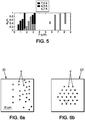
- the computer program based on method 2 allows a rearrangement of the initial distribution 20 into a desired, triangular distribution 20 ′.
- the method also comprises a step of avoiding collision between the vortex displaced by method 2 and the other vortices of the vortex distribution 20.
- the Nb film of sample 4 has a thickness d S of the order of 5 nm.
- the vortex moves over a distance of 300 nm with a time constant of 10 ps.
- Such a displacement frequency ensures the use of method 2 for storing information.
- Method 2 is particularly applicable to a Josephson junction provided with an Abrikosov vortex to control a value of the critical current of the Josephson junction.
- a Josephson junction a multilayer, preferably three-layer stacking of two thin layers of the superconducting element separated by a weak link.
- the weak link is constituted in particular by a thin layer of a insulating material or metal.
- the critical current is the maximum current which can pass through the Josephson junction.
- the method according to the present invention makes it possible to control the movement of each vortex of a set of vortexes in a reliable and rapid manner and advantageously applies to the uses described above (distribution of vortexes, storage of information, Josephson junction).
Landscapes
- Superconductor Devices And Manufacturing Methods Thereof (AREA)
Claims (16)
- Verfahren zur Kontrolle der einzelnen Verlagerung jedes Abrikossow-Vortex einer Wirbelverteilung eines Elements (4) ("Supraleiterelement"), das aus einem Supraleitermaterial und einer Sichtanzeigeschicht (11) besteht, wobei die Sichtanzeigeschicht (11) derart konfiguriert ist, dass sie die Polarisation des Auflichtes (13) ändert,
umfassend inhomogenes Heizen des Supraleiterelements mit dem Abrikossow-Vortex in einem Heizbereich, so dass der Abrikossow-Vortex in Richtung des Heizbereichs verlagert wird. - Verfahren nach Anspruch 1, wobei im Schritt des inhomogenen Heizens des Supraleiterelements der Heizbereich durch die Anwendung eines Laserstrahls geheizt wird.
- Verfahren nach Anspruch 2, umfassend Fokussieren des Laserstrahls im Heizbereich.
- Verfahren nach einem der Ansprüche 2 oder 3, wobei im Heizschritt der Laserstrahl eine auf den Vortex gerichtete Anziehungskraft mit folgendem Wert erzeugt:

- Verfahren nach vorstehendem Anspruch, wobei sich der Abrikossow-Vortex hin zum Heizereich verlagert, wenn die vom Laserstrahl erzeugte Anziehungskraft größer ist als eine Pinning-Kraft des Abrikossow-Vortex im Supraleiterelement.
- Verfahren nach vorstehendem Anspruch, wobei die Pinning-Kraft gleich Fp = jc Φ0 , ist, wobei Φ0 ein magnetisches Flussquantum ist und jc ein kritischer Strom des Supraleiterelements ist.
- Verfahren nach einem der Ansprüche 2 - 6, wobei eine Leistung des Lasers zwischen 1 und 1000 µW liegt.
- Verfahren nach einem der Ansprüche 2 - 7, wobei eine Wellenlänge des Lasers im sichtbaren elektromagnetischen Spektrum liegt.
- Verfahren nach einem der Ansprüche 5 - 8, umfassend Ermitteln des Werts der Pinning-Kraft für eine vom Laserstrahl zur Verlagerung des Abrikossow-Vortex anzuwendende minimale Kraft.
- Verwendung des Verfahrens nach einem der vorstehenden Ansprüche zur Bildung einer Wirbelverteilung in einem Supraleiterelement, wobei das Verfahren nach einem der vorstehenden Ansprüche auf mindestens einen Vortex einer anfänglichen Wirbelverteilung angewendet wird.
- Verwendung nach vorstehendem Anspruch, wobei das Verfahren nach einem der Ansprüche 1 - 9 sukzessiv auf jeden Vortex der Wirbelverteilung angewendet wird.
- Verwendung nach einem der Ansprüche 10 oder 11, umfassend Vermeiden einer Kollision zwischen dem durch das Verfahren nach einem der Ansprüche 1 - 9 verlagerten Vortex und den übrigen Vortizes der Wirbelverteilung.
- Verwendung des Verfahrens nach einem der Ansprüche 1 - 9 auf einen Josephson-Übergang mit Abrikossow-Vortex, um einen Wert eines kritischen Stroms des Josephson-Übergangs zu kontrollieren.
- Verwendung des Verfahrens nach einem der Ansprüche 1 - 9 zur Speicherung von Informationen, wobei die Informationen durch die Verlagerung des Abrikossow-Vortex geschrieben werden.
- Computerprogramm, umfassend eine Befehlsfolge, die bei Ausführung durch einen Prozessor die Schritte des Verfahrens nach einem der Ansprüche 1 - 9 ausführt.
- Nicht flüchtiger computerlesbarer Datenträger, umfassend ein Computerprogramm nach vorstehendem Anspruch.
Applications Claiming Priority (2)
| Application Number | Priority Date | Filing Date | Title |
|---|---|---|---|
| FR1558027A FR3040544B1 (fr) | 2015-08-28 | 2015-08-28 | Procede de controle de deplacement d'un vortex d'abrikosov |
| PCT/FR2016/052105 WO2017037361A1 (fr) | 2015-08-28 | 2016-08-23 | Procédé de contrôle de déplacement d'un vortex d'abrikosov |
Publications (2)
| Publication Number | Publication Date |
|---|---|
| EP3341978A1 EP3341978A1 (de) | 2018-07-04 |
| EP3341978B1 true EP3341978B1 (de) | 2020-04-29 |
Family
ID=55299552
Family Applications (1)
| Application Number | Title | Priority Date | Filing Date |
|---|---|---|---|
| EP16766996.9A Active EP3341978B1 (de) | 2015-08-28 | 2016-08-23 | Kontrollverfahren für eine verlagerung eines abrikosov wirbels |
Country Status (4)
| Country | Link |
|---|---|
| US (1) | US20180248104A1 (de) |
| EP (1) | EP3341978B1 (de) |
| FR (1) | FR3040544B1 (de) |
| WO (1) | WO2017037361A1 (de) |
Families Citing this family (2)
| Publication number | Priority date | Publication date | Assignee | Title |
|---|---|---|---|---|
| US11121302B2 (en) | 2018-10-11 | 2021-09-14 | SeeQC, Inc. | System and method for superconducting multi-chip module |
| JP2024526085A (ja) | 2021-06-11 | 2024-07-17 | シーク, インコーポレイテッド | 超伝導量子回路のための磁束バイアスのシステム及び方法 |
-
2015
- 2015-08-28 FR FR1558027A patent/FR3040544B1/fr not_active Expired - Fee Related
-
2016
- 2016-08-23 US US15/754,346 patent/US20180248104A1/en not_active Abandoned
- 2016-08-23 WO PCT/FR2016/052105 patent/WO2017037361A1/fr not_active Ceased
- 2016-08-23 EP EP16766996.9A patent/EP3341978B1/de active Active
Non-Patent Citations (1)
| Title |
|---|
| None * |
Also Published As
| Publication number | Publication date |
|---|---|
| FR3040544B1 (fr) | 2018-08-10 |
| US20180248104A1 (en) | 2018-08-30 |
| WO2017037361A1 (fr) | 2017-03-09 |
| FR3040544A1 (fr) | 2017-03-03 |
| EP3341978A1 (de) | 2018-07-04 |
Similar Documents
| Publication | Publication Date | Title |
|---|---|---|
| EP1506581B1 (de) | Supraleitende quanten-bit-einrichtung mit josephson-übergängen | |
| Pflug et al. | Case study on the dynamics of ultrafast laser heating and ablation of gold thin films by ultrafast pump-probe reflectometry and ellipsometry | |
| EP3341978B1 (de) | Kontrollverfahren für eine verlagerung eines abrikosov wirbels | |
| US3851174A (en) | Light detector for the nanosecond-dc pulse width range | |
| Satoh et al. | Ultrafast pump-probe microscopic imaging of femtosecond laser-induced melting and ablation in single-crystalline silicon carbide | |
| Strohauer et al. | Site‐selective enhancement of superconducting nanowire single‐photon detectors via local helium ion irradiation | |
| CA1317097C (fr) | Procede de detection de fin de polissage d'une tete magnetique couches minces | |
| Bananej et al. | The effect of porosity on the laser induced damage threshold of TiO2 and ZrO2 single layer films | |
| EP2525200B1 (de) | Thermoelektrische Komponente mit plasmonischer Führung, die eine Messvorrichtung der gekoppelten Leistung im geführten Modus umfasst | |
| Rütten et al. | Localised states and their capture characteristics in amorphous phase-change materials | |
| Huang et al. | Thermal detection of single photons using Dirac fermions | |
| Ivanov et al. | Imitating the effect of amplified spontaneous emission pedestal at relativistically intense laser interaction with nanostructured solid targets | |
| CN113030016A (zh) | 基于弱测量的外尔半金属类型识别及外尔锥倾斜度测量方法 | |
| WO2020239957A1 (fr) | Procédé de conception d'un composant supraconducteur et dispositifs associés | |
| Ganser et al. | Time-resolved optical measurement of thermal transport by surface plasmon polaritons in thin metal stripes | |
| EP3143390B1 (de) | Verfahren zur herstellung eines prüfkopfes eines zerstörungsfreien wirbelstromprüfsensors | |
| Xu et al. | Comparison of defects responsible for nanosecond laser-induced damage and ablation in common high index optical coatings | |
| WO1994012857A1 (fr) | Procede et appareil pour mesurer par ellipsometrie la temperature d'un objet, notamment semi-conducteur | |
| Yang et al. | Proximitized Josephson junctions in highly-doped InAs nanowires robust to optical illumination | |
| Harrabi et al. | Characterization of the current-induced resistive spots in superconducting YBa 2 Cu 3 O 7 strips | |
| Huynh et al. | In situ probing of pulsed laser melting and laser-induced periodic surface structures formation by dynamic reflectivity | |
| Berezhinskiĭ et al. | Size effects in the internal reflection in gold cluster films in polarization modulation experiments | |
| Liu et al. | Revealing Nanoscale Inhomogeneities in a Superconducting Nanowire through Self-Heating Hotspot Scanning and Mapping | |
| Wong et al. | Thermoelectric effects at a Germanium-electrolyte interface: measuring 100 nK temperature oscillations at room temperature | |
| EP3627103B1 (de) | Messvorrichtung, die einen aufgehängten halbleiterdraht umfasst |
Legal Events
| Date | Code | Title | Description |
|---|---|---|---|
| STAA | Information on the status of an ep patent application or granted ep patent |
Free format text: STATUS: THE INTERNATIONAL PUBLICATION HAS BEEN MADE |
|
| PUAI | Public reference made under article 153(3) epc to a published international application that has entered the european phase |
Free format text: ORIGINAL CODE: 0009012 |
|
| STAA | Information on the status of an ep patent application or granted ep patent |
Free format text: STATUS: REQUEST FOR EXAMINATION WAS MADE |
|
| 17P | Request for examination filed |
Effective date: 20180221 |
|
| AK | Designated contracting states |
Kind code of ref document: A1 Designated state(s): AL AT BE BG CH CY CZ DE DK EE ES FI FR GB GR HR HU IE IS IT LI LT LU LV MC MK MT NL NO PL PT RO RS SE SI SK SM TR |
|
| AX | Request for extension of the european patent |
Extension state: BA ME |
|
| DAV | Request for validation of the european patent (deleted) | ||
| DAX | Request for extension of the european patent (deleted) | ||
| GRAP | Despatch of communication of intention to grant a patent |
Free format text: ORIGINAL CODE: EPIDOSNIGR1 |
|
| STAA | Information on the status of an ep patent application or granted ep patent |
Free format text: STATUS: GRANT OF PATENT IS INTENDED |
|
| INTG | Intention to grant announced |
Effective date: 20191216 |
|
| GRAS | Grant fee paid |
Free format text: ORIGINAL CODE: EPIDOSNIGR3 |
|
| GRAA | (expected) grant |
Free format text: ORIGINAL CODE: 0009210 |
|
| STAA | Information on the status of an ep patent application or granted ep patent |
Free format text: STATUS: THE PATENT HAS BEEN GRANTED |
|
| AK | Designated contracting states |
Kind code of ref document: B1 Designated state(s): AL AT BE BG CH CY CZ DE DK EE ES FI FR GB GR HR HU IE IS IT LI LT LU LV MC MK MT NL NO PL PT RO RS SE SI SK SM TR |
|
| REG | Reference to a national code |
Ref country code: GB Ref legal event code: FG4D Free format text: NOT ENGLISH |
|
| REG | Reference to a national code |
Ref country code: CH Ref legal event code: EP |
|
| REG | Reference to a national code |
Ref country code: AT Ref legal event code: REF Ref document number: 1264614 Country of ref document: AT Kind code of ref document: T Effective date: 20200515 |
|
| REG | Reference to a national code |
Ref country code: DE Ref legal event code: R096 Ref document number: 602016035166 Country of ref document: DE |
|
| REG | Reference to a national code |
Ref country code: IE Ref legal event code: FG4D Free format text: LANGUAGE OF EP DOCUMENT: FRENCH |
|
| REG | Reference to a national code |
Ref country code: NL Ref legal event code: MP Effective date: 20200429 |
|
| REG | Reference to a national code |
Ref country code: LT Ref legal event code: MG4D |
|
| PG25 | Lapsed in a contracting state [announced via postgrant information from national office to epo] |
Ref country code: GR Free format text: LAPSE BECAUSE OF FAILURE TO SUBMIT A TRANSLATION OF THE DESCRIPTION OR TO PAY THE FEE WITHIN THE PRESCRIBED TIME-LIMIT Effective date: 20200730 Ref country code: LT Free format text: LAPSE BECAUSE OF FAILURE TO SUBMIT A TRANSLATION OF THE DESCRIPTION OR TO PAY THE FEE WITHIN THE PRESCRIBED TIME-LIMIT Effective date: 20200429 Ref country code: FI Free format text: LAPSE BECAUSE OF FAILURE TO SUBMIT A TRANSLATION OF THE DESCRIPTION OR TO PAY THE FEE WITHIN THE PRESCRIBED TIME-LIMIT Effective date: 20200429 Ref country code: IS Free format text: LAPSE BECAUSE OF FAILURE TO SUBMIT A TRANSLATION OF THE DESCRIPTION OR TO PAY THE FEE WITHIN THE PRESCRIBED TIME-LIMIT Effective date: 20200829 Ref country code: SE Free format text: LAPSE BECAUSE OF FAILURE TO SUBMIT A TRANSLATION OF THE DESCRIPTION OR TO PAY THE FEE WITHIN THE PRESCRIBED TIME-LIMIT Effective date: 20200429 Ref country code: NO Free format text: LAPSE BECAUSE OF FAILURE TO SUBMIT A TRANSLATION OF THE DESCRIPTION OR TO PAY THE FEE WITHIN THE PRESCRIBED TIME-LIMIT Effective date: 20200729 Ref country code: PT Free format text: LAPSE BECAUSE OF FAILURE TO SUBMIT A TRANSLATION OF THE DESCRIPTION OR TO PAY THE FEE WITHIN THE PRESCRIBED TIME-LIMIT Effective date: 20200831 |
|
| REG | Reference to a national code |
Ref country code: AT Ref legal event code: MK05 Ref document number: 1264614 Country of ref document: AT Kind code of ref document: T Effective date: 20200429 |
|
| PG25 | Lapsed in a contracting state [announced via postgrant information from national office to epo] |
Ref country code: BG Free format text: LAPSE BECAUSE OF FAILURE TO SUBMIT A TRANSLATION OF THE DESCRIPTION OR TO PAY THE FEE WITHIN THE PRESCRIBED TIME-LIMIT Effective date: 20200729 Ref country code: HR Free format text: LAPSE BECAUSE OF FAILURE TO SUBMIT A TRANSLATION OF THE DESCRIPTION OR TO PAY THE FEE WITHIN THE PRESCRIBED TIME-LIMIT Effective date: 20200429 Ref country code: RS Free format text: LAPSE BECAUSE OF FAILURE TO SUBMIT A TRANSLATION OF THE DESCRIPTION OR TO PAY THE FEE WITHIN THE PRESCRIBED TIME-LIMIT Effective date: 20200429 Ref country code: LV Free format text: LAPSE BECAUSE OF FAILURE TO SUBMIT A TRANSLATION OF THE DESCRIPTION OR TO PAY THE FEE WITHIN THE PRESCRIBED TIME-LIMIT Effective date: 20200429 |
|
| PG25 | Lapsed in a contracting state [announced via postgrant information from national office to epo] |
Ref country code: AL Free format text: LAPSE BECAUSE OF FAILURE TO SUBMIT A TRANSLATION OF THE DESCRIPTION OR TO PAY THE FEE WITHIN THE PRESCRIBED TIME-LIMIT Effective date: 20200429 Ref country code: NL Free format text: LAPSE BECAUSE OF FAILURE TO SUBMIT A TRANSLATION OF THE DESCRIPTION OR TO PAY THE FEE WITHIN THE PRESCRIBED TIME-LIMIT Effective date: 20200429 |
|
| PG25 | Lapsed in a contracting state [announced via postgrant information from national office to epo] |
Ref country code: EE Free format text: LAPSE BECAUSE OF FAILURE TO SUBMIT A TRANSLATION OF THE DESCRIPTION OR TO PAY THE FEE WITHIN THE PRESCRIBED TIME-LIMIT Effective date: 20200429 Ref country code: DK Free format text: LAPSE BECAUSE OF FAILURE TO SUBMIT A TRANSLATION OF THE DESCRIPTION OR TO PAY THE FEE WITHIN THE PRESCRIBED TIME-LIMIT Effective date: 20200429 Ref country code: AT Free format text: LAPSE BECAUSE OF FAILURE TO SUBMIT A TRANSLATION OF THE DESCRIPTION OR TO PAY THE FEE WITHIN THE PRESCRIBED TIME-LIMIT Effective date: 20200429 Ref country code: SM Free format text: LAPSE BECAUSE OF FAILURE TO SUBMIT A TRANSLATION OF THE DESCRIPTION OR TO PAY THE FEE WITHIN THE PRESCRIBED TIME-LIMIT Effective date: 20200429 Ref country code: ES Free format text: LAPSE BECAUSE OF FAILURE TO SUBMIT A TRANSLATION OF THE DESCRIPTION OR TO PAY THE FEE WITHIN THE PRESCRIBED TIME-LIMIT Effective date: 20200429 Ref country code: CZ Free format text: LAPSE BECAUSE OF FAILURE TO SUBMIT A TRANSLATION OF THE DESCRIPTION OR TO PAY THE FEE WITHIN THE PRESCRIBED TIME-LIMIT Effective date: 20200429 Ref country code: RO Free format text: LAPSE BECAUSE OF FAILURE TO SUBMIT A TRANSLATION OF THE DESCRIPTION OR TO PAY THE FEE WITHIN THE PRESCRIBED TIME-LIMIT Effective date: 20200429 Ref country code: IT Free format text: LAPSE BECAUSE OF FAILURE TO SUBMIT A TRANSLATION OF THE DESCRIPTION OR TO PAY THE FEE WITHIN THE PRESCRIBED TIME-LIMIT Effective date: 20200429 |
|
| REG | Reference to a national code |
Ref country code: DE Ref legal event code: R097 Ref document number: 602016035166 Country of ref document: DE |
|
| PG25 | Lapsed in a contracting state [announced via postgrant information from national office to epo] |
Ref country code: PL Free format text: LAPSE BECAUSE OF FAILURE TO SUBMIT A TRANSLATION OF THE DESCRIPTION OR TO PAY THE FEE WITHIN THE PRESCRIBED TIME-LIMIT Effective date: 20200429 Ref country code: SK Free format text: LAPSE BECAUSE OF FAILURE TO SUBMIT A TRANSLATION OF THE DESCRIPTION OR TO PAY THE FEE WITHIN THE PRESCRIBED TIME-LIMIT Effective date: 20200429 |
|
| PLBE | No opposition filed within time limit |
Free format text: ORIGINAL CODE: 0009261 |
|
| STAA | Information on the status of an ep patent application or granted ep patent |
Free format text: STATUS: NO OPPOSITION FILED WITHIN TIME LIMIT |
|
| PG25 | Lapsed in a contracting state [announced via postgrant information from national office to epo] |
Ref country code: MC Free format text: LAPSE BECAUSE OF FAILURE TO SUBMIT A TRANSLATION OF THE DESCRIPTION OR TO PAY THE FEE WITHIN THE PRESCRIBED TIME-LIMIT Effective date: 20200429 |
|
| REG | Reference to a national code |
Ref country code: CH Ref legal event code: PL |
|
| 26N | No opposition filed |
Effective date: 20210201 |
|
| PG25 | Lapsed in a contracting state [announced via postgrant information from national office to epo] |
Ref country code: LU Free format text: LAPSE BECAUSE OF NON-PAYMENT OF DUE FEES Effective date: 20200823 Ref country code: CH Free format text: LAPSE BECAUSE OF NON-PAYMENT OF DUE FEES Effective date: 20200831 Ref country code: LI Free format text: LAPSE BECAUSE OF NON-PAYMENT OF DUE FEES Effective date: 20200831 |
|
| REG | Reference to a national code |
Ref country code: BE Ref legal event code: MM Effective date: 20200831 |
|
| PG25 | Lapsed in a contracting state [announced via postgrant information from national office to epo] |
Ref country code: SI Free format text: LAPSE BECAUSE OF FAILURE TO SUBMIT A TRANSLATION OF THE DESCRIPTION OR TO PAY THE FEE WITHIN THE PRESCRIBED TIME-LIMIT Effective date: 20200429 |
|
| PG25 | Lapsed in a contracting state [announced via postgrant information from national office to epo] |
Ref country code: BE Free format text: LAPSE BECAUSE OF NON-PAYMENT OF DUE FEES Effective date: 20200831 Ref country code: IE Free format text: LAPSE BECAUSE OF NON-PAYMENT OF DUE FEES Effective date: 20200823 |
|
| PG25 | Lapsed in a contracting state [announced via postgrant information from national office to epo] |
Ref country code: TR Free format text: LAPSE BECAUSE OF FAILURE TO SUBMIT A TRANSLATION OF THE DESCRIPTION OR TO PAY THE FEE WITHIN THE PRESCRIBED TIME-LIMIT Effective date: 20200429 Ref country code: MT Free format text: LAPSE BECAUSE OF FAILURE TO SUBMIT A TRANSLATION OF THE DESCRIPTION OR TO PAY THE FEE WITHIN THE PRESCRIBED TIME-LIMIT Effective date: 20200429 Ref country code: CY Free format text: LAPSE BECAUSE OF FAILURE TO SUBMIT A TRANSLATION OF THE DESCRIPTION OR TO PAY THE FEE WITHIN THE PRESCRIBED TIME-LIMIT Effective date: 20200429 |
|
| PG25 | Lapsed in a contracting state [announced via postgrant information from national office to epo] |
Ref country code: MK Free format text: LAPSE BECAUSE OF FAILURE TO SUBMIT A TRANSLATION OF THE DESCRIPTION OR TO PAY THE FEE WITHIN THE PRESCRIBED TIME-LIMIT Effective date: 20200429 |
|
| REG | Reference to a national code |
Ref country code: DE Ref legal event code: R079 Ref document number: 602016035166 Country of ref document: DE Free format text: PREVIOUS MAIN CLASS: H01L0039140000 Ipc: H10N0060200000 |
|
| REG | Reference to a national code |
Ref country code: DE Ref legal event code: R082 Ref document number: 602016035166 Country of ref document: DE Representative=s name: BSB PATENTANWAELTE SCHUETTE & ENGELEN PARTNERS, DE |
|
| PGFP | Annual fee paid to national office [announced via postgrant information from national office to epo] |
Ref country code: DE Payment date: 20250929 Year of fee payment: 10 |
|
| PGFP | Annual fee paid to national office [announced via postgrant information from national office to epo] |
Ref country code: GB Payment date: 20250827 Year of fee payment: 10 |
|
| PGFP | Annual fee paid to national office [announced via postgrant information from national office to epo] |
Ref country code: FR Payment date: 20250827 Year of fee payment: 10 |