EP3342005B1 - Bloc de jonction électrique - Google Patents
Bloc de jonction électrique Download PDFInfo
- Publication number
- EP3342005B1 EP3342005B1 EP16757612.3A EP16757612A EP3342005B1 EP 3342005 B1 EP3342005 B1 EP 3342005B1 EP 16757612 A EP16757612 A EP 16757612A EP 3342005 B1 EP3342005 B1 EP 3342005B1
- Authority
- EP
- European Patent Office
- Prior art keywords
- plug
- terminal
- contact
- terminal block
- another
- Prior art date
- Legal status (The legal status is an assumption and is not a legal conclusion. Google has not performed a legal analysis and makes no representation as to the accuracy of the status listed.)
- Active
Links
Images


Classifications
-
- H—ELECTRICITY
- H01—ELECTRIC ELEMENTS
- H01R—ELECTRICALLY-CONDUCTIVE CONNECTIONS; STRUCTURAL ASSOCIATIONS OF A PLURALITY OF MUTUALLY-INSULATED ELECTRICAL CONNECTING ELEMENTS; COUPLING DEVICES; CURRENT COLLECTORS
- H01R9/00—Structural associations of a plurality of mutually-insulated electrical connecting elements, e.g. terminal strips or terminal blocks; Terminals or binding posts mounted upon a base or in a case; Bases therefor
- H01R9/22—Bases, e.g. strip, block, panel
- H01R9/24—Terminal blocks
- H01R9/26—Clip-on terminal blocks for side-by-side rail- or strip-mounting
- H01R9/2625—Clip-on terminal blocks for side-by-side rail- or strip-mounting with built-in electrical component
- H01R9/2666—Clip-on terminal blocks for side-by-side rail- or strip-mounting with built-in electrical component with built-in test-points
-
- H—ELECTRICITY
- H01—ELECTRIC ELEMENTS
- H01R—ELECTRICALLY-CONDUCTIVE CONNECTIONS; STRUCTURAL ASSOCIATIONS OF A PLURALITY OF MUTUALLY-INSULATED ELECTRICAL CONNECTING ELEMENTS; COUPLING DEVICES; CURRENT COLLECTORS
- H01R13/00—Details of coupling devices of the kinds covered by groups H01R12/70 or H01R24/00 - H01R33/00
- H01R13/66—Structural association with built-in electrical component
- H01R13/70—Structural association with built-in electrical component with built-in switch
- H01R13/703—Structural association with built-in electrical component with built-in switch operated by engagement or disengagement of coupling parts, e.g. dual-continuity coupling part
- H01R13/7031—Shorting, shunting or bussing of different terminals interrupted or effected on engagement of coupling part, e.g. for ESD protection, line continuity
- H01R13/7033—Shorting, shunting or bussing of different terminals interrupted or effected on engagement of coupling part, e.g. for ESD protection, line continuity making use of elastic extensions of the terminals
-
- H—ELECTRICITY
- H01—ELECTRIC ELEMENTS
- H01R—ELECTRICALLY-CONDUCTIVE CONNECTIONS; STRUCTURAL ASSOCIATIONS OF A PLURALITY OF MUTUALLY-INSULATED ELECTRICAL CONNECTING ELEMENTS; COUPLING DEVICES; CURRENT COLLECTORS
- H01R9/00—Structural associations of a plurality of mutually-insulated electrical connecting elements, e.g. terminal strips or terminal blocks; Terminals or binding posts mounted upon a base or in a case; Bases therefor
- H01R9/22—Bases, e.g. strip, block, panel
- H01R9/223—Insulating enclosures for terminals
-
- H—ELECTRICITY
- H01—ELECTRIC ELEMENTS
- H01R—ELECTRICALLY-CONDUCTIVE CONNECTIONS; STRUCTURAL ASSOCIATIONS OF A PLURALITY OF MUTUALLY-INSULATED ELECTRICAL CONNECTING ELEMENTS; COUPLING DEVICES; CURRENT COLLECTORS
- H01R9/00—Structural associations of a plurality of mutually-insulated electrical connecting elements, e.g. terminal strips or terminal blocks; Terminals or binding posts mounted upon a base or in a case; Bases therefor
- H01R9/22—Bases, e.g. strip, block, panel
- H01R9/24—Terminal blocks
- H01R9/2491—Terminal blocks structurally associated with plugs or sockets
-
- H—ELECTRICITY
- H01—ELECTRIC ELEMENTS
- H01R—ELECTRICALLY-CONDUCTIVE CONNECTIONS; STRUCTURAL ASSOCIATIONS OF A PLURALITY OF MUTUALLY-INSULATED ELECTRICAL CONNECTING ELEMENTS; COUPLING DEVICES; CURRENT COLLECTORS
- H01R2201/00—Connectors or connections adapted for particular applications
- H01R2201/20—Connectors or connections adapted for particular applications for testing or measuring purposes
-
- H—ELECTRICITY
- H01—ELECTRIC ELEMENTS
- H01R—ELECTRICALLY-CONDUCTIVE CONNECTIONS; STRUCTURAL ASSOCIATIONS OF A PLURALITY OF MUTUALLY-INSULATED ELECTRICAL CONNECTING ELEMENTS; COUPLING DEVICES; CURRENT COLLECTORS
- H01R24/00—Two-part coupling devices, or either of their cooperating parts, characterised by their overall structure
- H01R24/58—Contacts spaced along longitudinal axis of engagement
-
- H—ELECTRICITY
- H01—ELECTRIC ELEMENTS
- H01R—ELECTRICALLY-CONDUCTIVE CONNECTIONS; STRUCTURAL ASSOCIATIONS OF A PLURALITY OF MUTUALLY-INSULATED ELECTRICAL CONNECTING ELEMENTS; COUPLING DEVICES; CURRENT COLLECTORS
- H01R9/00—Structural associations of a plurality of mutually-insulated electrical connecting elements, e.g. terminal strips or terminal blocks; Terminals or binding posts mounted upon a base or in a case; Bases therefor
- H01R9/22—Bases, e.g. strip, block, panel
- H01R9/24—Terminal blocks
- H01R9/26—Clip-on terminal blocks for side-by-side rail- or strip-mounting
- H01R9/2625—Clip-on terminal blocks for side-by-side rail- or strip-mounting with built-in electrical component
- H01R9/2633—Clip-on terminal blocks for side-by-side rail- or strip-mounting with built-in electrical component with built-in switch
Definitions
- the invention relates to an electrical terminal block, with a terminal housing, with at least two conductor connection elements arranged therein and with two current bars, each having a connection section and at least one resilient contact section, according to claim 1. 1.
- the invention relates to a terminal block consisting of at least two juxtaposed terminal blocks and at least one jumper, which has at least two legs.
- Electric terminal blocks have been used millions of times for the wiring of electrical systems and devices for decades.
- the terminals are often snapped onto mounting rails, which in turn can be arranged in a plurality in a switch cabinet.
- multiple terminal blocks can be fastened as a terminal block in a wall opening, in particular in an opening in a switch cabinet door. This has the advantage that one side of the terminals, the operator side, is accessible from outside the control cabinet without having to open the control cabinet, while the other side of the terminal, the connection side, is only accessible when the control cabinet is open.
- Screw terminals or spring-cage terminals are often used as conductor connection elements in terminal blocks.
- the clamping principle of tension spring terminals is similar to that of screw technology. While with screw terminals a tension sleeve pulls the conductor against the current bar by actuating the clamping screw, with the tension spring terminal this task is taken over by the tension spring.
- insulation displacement terminals and leg spring terminals are increasingly being used, which, compared to tension spring terminals, have the advantage that the terminal does not have to be opened with the aid of a tool to insert a conductor.
- Electrical terminal blocks are often connecting terminals, so that they have at least two conductor connection elements that are electrically connected to one another via an electrically conductive connecting rail, the current bar are.
- this basic type of terminal block which is often referred to as a through terminal
- disconnect terminals In switching, measuring, testing and control technology, through-type terminals with disconnection options are often used, which are therefore sometimes also referred to as disconnect terminals.
- the separation possibility realized with such a terminal block i. H.
- the separation point provided in the current bar enables different plugs with different functions to be plugged into the terminal block, which then contact the current bar at the separation point.
- test plugs can also be used as plugs, which can have special components and enable checking of the proper function of the circuit connected to the terminal block.
- the electrical terminal blocks are generally disc-shaped, they are usually plugged together with several other electrical terminal blocks to form a terminal block. A number of test plugs corresponding to the number of series terminals can then be plugged into such a terminal block.
- Terminal blocks with isolating points are used in particular to connect current transformers.
- An important functional feature is that a connected current transformer is short-circuited when the secondary circuit is disconnected from the load.
- a terminal block is known from which the present invention is based.
- This document also discloses a test plug and a test terminal block consisting of a plurality of series terminals arranged next to one another and a corresponding number of test plugs.
- the individual terminal blocks each have two current bars, the contact sections of which contact one another when the plug of a test plug is not inserted into the contact area formed by the contact sections. If the plug of a test plug is completely inserted into the contact area, the two contact sections separated from each other by the plug, the current flow then being passed through the plug so that a test process can be carried out.
- the terminal block and the associated test plug thus work according to the normally closed principle, since the connection between the two current bars of the terminal block is opened when the plug, which has two metal sections isolated from one another, is plugged into the contact area.
- the current bars in the known electrical terminal block are designed so that they form two contact areas that are arranged one behind the other in the direction of insertion of the plug.
- the formation of a defined second contact area, which is arranged in front of the first contact area in the insertion direction of the plug, ensures that when the plug is inserted, a secure electrical connection is first made between the metal sections of the plug of the test plug and the two current bars before the first contact area is opened upon further insertion of the plug and thereby the two current bars are electrically isolated from one another.
- cross-bridging to an adjacent terminal block is made by inserting the test terminal block into the terminal block, whereby a jumper must be plugged into two neighboring test terminals of the test terminal block.
- an electrical terminal block in the form of a test terminal is known.
- this series terminal two conductor connection elements and two current bars are also arranged in the housing.
- the two current bars each have a second contact section.
- the first contact sections are spaced from one another and are only connected to one another in an electrically conductive manner via the plug when the plug is inserted, so that this series terminal works according to the make contact principle.
- two further current bar pieces are arranged in the housing, with a recess in at least one of the current bar pieces is designed for plugging in one leg of a jumper.
- one of the current bar pieces is assigned to one of the current bars in such a way that the second contact section of a current bar contacts the assigned current bar piece due to the spring force of the current bar when no plug is inserted.
- the current bars of the terminal block are then each connected in an electrically conductive manner with their connection section to the conductor connection element and with their second contact section to the respective current bar piece. If a plug of a test plug is inserted into the contact area, the two current bars are deflected in such a way that the second contact section of a current bar is at a distance from the associated current bar piece.
- the electrical connection between a conductor connection element and the associated current bar piece is then interrupted.
- the present invention is based on the object of providing an electrical terminal block described at the beginning, which is particularly well suited for connecting current transformers, whereby it should be ensured that a cross connection between two conductor connection elements of two adjacent terminal blocks occurs automatically when a test or Isolating plug is plugged onto the terminal blocks.
- two leading spring elements are arranged in the terminal housing in the terminal block, so that when the plug of a test or isolating plug is inserted, this is first contacted by the contact sections of the spring elements before the plug meets the contact sections of the current bar and also contacts them. Before the plug of a test or isolating plug thus separates the contact between the contact sections of the two current bars, electrical contact is established between the plug and the additional spring elements. An electrically conductive connection is then established between each spring element and the associated current bar via the plug of a test or isolating plug inserted into the terminal block.
- the resilient contact sections of the two spring elements are each approximately C-shaped or V-shaped.
- the two mutually facing contact sections of the two spring elements serve as a kind of insertion funnel for the plug of the test or disconnect plug to be inserted, so that the risk of tilting is minimized and the plug is simultaneously guided into the contact area. Due to the design and bending of the contact sections of the spring elements, the contact force acting by the spring elements on an inserted plug can be easily adapted to the respective requirements.
- the two spring elements preferably also have a connection section in which the receptacle is designed for inserting a leg of a plug-in bridge.
- the spring elements can overall be approximately S-shaped, the connecting sections can also be used to securely fix and hold the spring elements in the terminal housing.
- the manufacture of the spring elements can be further simplified if a recess is punched out of the corresponding spring element, in particular its connecting section, as a receptacle for inserting a leg of a plug-in bridge.
- the spring elements can then be manufactured particularly easily as stamped and bent parts.
- the two current bars each have a second resilient contact section, the two second contact sections being slightly spaced from one another and together forming a second contact area for a plug of a test or isolating plug.
- the current bars are designed such that the second contact area of the current bars is arranged between the first contact area of the current bars and the contact area of the two spring elements. In the plug-in direction of the plug, the second contact area of the current bars is therefore located in front of the first contact area and behind the contact area of the two spring elements.
- the formation of the second contact area on the current bar ensures that an inserted plug of a test or isolating plug first connects the spring elements to the respective current bar before the electrical contact of the two current bars in the first contact area is separated by inserting the plug.
- the plug of a test or isolating plug is plugged into the electrical terminal block, this initially leads to the plug contacting the contact sections of the two spring elements with its two mutually insulated plug metals. If the plug is inserted further into the electrical terminal block, the plug metals of the plug also each contact a second resilient contact section of the current bar, so that in each case a spring element is electrically conductively connected to a current bar via a plug metal of the plug. Only when the plug is inserted further into the terminal block is the electrical contact between the first contact sections of the two current bars through the plug separated so that the conductor connection elements are then no longer electrically connected to one another.
- the two current bars can also be made from pieces of metal by punching them out and then bending them over and over.
- the two current bars preferably each consist of two individual metal strips which are connected to one another in an electrically conductive manner, in particular welded, soldered or riveted to one another.
- the connection section of a current bar can then be formed by the first metal strip and the contact section or sections of the current bar can be formed by the second metal strip. This simplifies the production of the current bars and it is also possible to use different materials and / or different cross-sections for the connection section on the one hand and the resilient contact sections on the other hand, which are selected according to the required rigidity and spring properties.
- the first metal strip forming the connection section can be designed to be relatively rigid, while the second metal strip itself is designed as a contact spring.
- the contact spring can be bent approximately in a C-shape, the first end of the contact spring forming the first contact section and the second end of the contact spring forming the second contact section.
- the object on which the invention is based is achieved in that one leg of the jumper is plugged into at least one spring element of the first terminal block and the corresponding spring element of the second terminal block.
- two conductor connection elements of the two terminal blocks are connected to one another in an electrically conductive manner when a plug of a test or isolating plug is inserted into each of the two terminal blocks, via which a spring element is electrically connected to the associated current bar.
- the cross-bridging takes place via the plug-in bridge plugged into the two terminal blocks, the legs of which are each inserted into a corresponding recess in a spring element Terminal blocks are plugged in, the spring elements being connected to the associated current bar and thus also to the associated conductor connection element in an electrically conductive manner when the test or isolating plug is plugged in via the plug of the test or isolating plug.
- the electrical terminal blocks which together form the terminal block, are each disk-shaped. So that a plurality of terminal blocks can together form a terminal block, the individual terminal blocks are preferably mechanically connected to one another, for which purpose the terminal blocks are locked together via corresponding latching elements formed in the terminal housing.
- the locking elements preferably consist of locking pins arranged on one side of the terminal housing and corresponding locking recesses which are formed in the other side of the terminal housing.
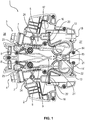
- the electrical terminal block 1 has a terminal housing 2 made of plastic which, in the illustrated embodiment, can be inserted and fastened in an opening in a wall, in particular a switch cabinet wall.
- connection elements for example tension spring terminals, leg spring terminals or insulation displacement terminals, can also be used as conductor connection elements.
- two current bars 5, 6 are also arranged, which are identical and are arranged mirror-symmetrically to one another.
- the current bars 5, 6 each have at one end a connection section 7, 7 'which is assigned to one of the two conductor connection elements 3, 4, ie is inserted into the screw terminals.
- the two conductor connection elements 3, 4 each have a first contact section 8, 8 ', which together have a resilient first contact area 9 for receiving the plug 10 of an in Fig. 2 test plug 11 shown or one in Fig. 5 Forming connector 29 shown. How out Fig.
- the electrical terminal block 1 also has two spring elements 12, 13 arranged in the terminal housing 2, which in the basic state of the terminal block 1 according to FIG Fig. 1 , ie when the test plug 11 is not inserted, they are not connected to the current bars 5, 6 in an electrically conductive manner.
- the two spring elements 12, 13 each have a resilient contact section 14, 14 ', the spring elements 12, 13 being arranged mirror-symmetrically to one another in such a way that the contact sections 14, 14' have a further contact area 15 for a plug 10 of a test plug 11 or a disconnecting plug 29 form.
- the contact sections 14, 14 'can as shown in the figures, have a spacing from one another so that they do not contact one another. In principle, however, the contact sections 14, 14 'can also be designed and arranged in such a way that the contact sections 14, 14' make contact when no plug 10 is inserted.
- the spring elements 12, 13 serve to create a transverse bridge between two terminal blocks 1, 1 'in a simple manner.
- a recess 16 is formed in at least one of the two spring elements 12, 13 as a receptacle for a leg 17 of a plug-in bridge 18.
- two spring elements 12 or 13 are then electrically connected to one another via the two legs 17 of a plug-in bridge 18.
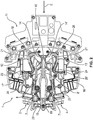
- the plug 10 of a test plug 11 is plugged into a terminal block 1, this results in a respective spring element 12, 13 being connected in an electrically conductive manner to the associated current bar 5, 6 via a plug metal 19, 19 '.
- the two current bars 5, 6 in the first contact area 9 are separated from one another by the plug 10, so that the two conductor connection elements 3, 4 are no longer electrically connected to one another via the current bars 5, 6.
- the spring elements 12, 13, which can be easily produced from a metal strip by punching and then bending, each have a substantially straight connecting section in addition to the approximately C-shaped contact sections 14, 14 ' 20, 20 ', in which the recess 16 for inserting the leg 10 of a jumper 11 is punched out.
- the spring elements 12, 13 thus have an approximately S-shaped shape, the spring elements 12, 13 preferably being fastened in the terminal housing 2 via appropriately designed projections.
- the current bars 5, 6 each have a second resilient contact section 21, 21 '.
- the second contact sections 21, 21 ' which are spaced apart from one another, together form a second contact area 22, which is arranged in the insertion direction E of the plug 10 in front of the first contact area 9 of the current bars 5, 6 and behind the contact area 15 of the spring elements 12, 13 .
- the two current bars 5, 6 each consist of two individual elongated metal strips 23, 24 which are soldered, welded or riveted to one another in the transition area.
- the two connection sections 7, 7 ' are each formed by the first angled metal strip 23, whose ends facing away from the second metal strips 24 each protrude into the clamping body of a screw terminal 3, 4. While the first metal strips 23 are relatively rigid, the overall approximately C-shaped second metal strips 24 are designed as contact springs, whereby the contact forces required in the first contact area 9 and in the second contact area 22 can be implemented in a simple manner.
- the current bars 5, 6 can be optimally adapted to the different requirements in the connection section 7, 7 'on the one hand and in the contact areas 9, 22 on the other hand.
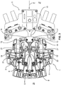
- a modular terminal block consisting of two terminal blocks 1, 1 'is shown, the two terminal blocks 1, 1' being connected to one another via a jumper 18, the two plugs 17 of which are each inserted into a recess 16 in a spring element 12 of the two terminal blocks 1, 1 ' are.
- an opening 25 for inserting the plug 10 of a test plug 11 into the contact areas 9, 15 and 22 is formed in the center.
- a further opening 26 for inserting the leg 17 of a plug-in bridge 18 into the recess 16 in a connecting section 20, 21 of a spring element 12, 13 is formed on both sides of the opening 25.
- the openings 25, 26 are accessible from the first side 27, the operator side of the terminal block 1.
- This has the advantage that, when the terminal block 1 or a corresponding terminal block is arranged in an opening in a switch cabinet door, both a test plug 11 and a jumper 18 can be inserted into the terminal blocks 1, 1 'without having to open the switch cabinet door .
- Another advantage is that the jumpers 18 can be easily recognized by an operator from the front, which also clearly shows the terminal blocks to which current transformers are connected.
- the connection of the electrical lines, for example a current transformer takes place from the second side 28, the connection side of the terminal block 1, which is then located within the switch cabinet.
- an isolating plug 29 can also be inserted into the opening 25 in the terminal housing 2.
- Fig. 5 two such disconnecting plugs 29, which are arranged next to one another, are shown which, for example, are inserted into the two in Fig. 4 Terminal blocks 1, 1 'shown can be inserted.
- the isolating plug 29 also has a plug 10 with two plug-in metals 19, 19 'that are insulated from one another.
- a grip area 20 is also formed on the isolating plug 29, in which a license plate 31 can be attached.
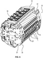
- a terminal block consisting of several terminal blocks 1 is shown.
- a fastening clamp 32 is arranged in each case, which are used for simple and secure fastening of the terminal block in an opening of a control cabinet door.
- a fixing element 34 is arranged displaceably in the terminal housing 33 of the fastening clamp 32 and can be brought into a clamping position with the aid of an actuating element, for example a screwdriver.
Landscapes
- Connections Arranged To Contact A Plurality Of Conductors (AREA)
- Connector Housings Or Holding Contact Members (AREA)
Claims (10)
- Borne sur rail électrique (1), comprenant un boîtier de borne (2) doté d'au moins deux éléments de connexion de conducteur (3, 4) disposés dans celui-ci et de deux rails de courant (5, 6), les rails de courant (5, 6) présentant respectivement une partie de connexion (7, 7') et au moins une partie de contact élastique (8, 8'),
les parties de connexion (7, 7') étant associées à un élément de connexion de conducteur (3, 4) respectivement, et les parties de contact (8, 8') formant ensemble une zone de contact (9) pour recevoir et contacter la fiche (10) d'une fiche de test (11) ou d'une fiche de sectionnement (29), et
les parties de contact (8, 8') entrant en contact l'une avec l'autre si aucune fiche (10) n'est enfichée de sorte que les deux éléments de connexion de conducteur (3, 4) sont reliés électriquement l'un à l'autre par l'intermédiaire des deux rails de courant (5, 6),
caractérisée en ce que
deux éléments de ressort (12, 13) sont disposés dans le boîtier de borne (2) et présentent respectivement une partie de contact élastique (14, 14'),
les parties de contact (14, 14') des deux éléments de ressort (12, 13) constituent ensemble une zone de contact supplémentaire (15) pour la fiche (10) qui est disposée dans la direction d'enfichage (E) de la fiche (10) avant la zone de contact (9) des rails de courant (5, 6),
et au moins l'un des éléments de ressort (12, 13) présente un logement (16) pour une branche (17) d'un cavalier (18),
dans laquelle respectivement un élément de ressort (12, 13) est relié de manière électriquement conductrice par la fiche (10) à l'un des rails de courant (5, 6) si la fiche (10) d'une fiche de test (11) ou d'une fiche de sectionnement (29) est enfichée dans la borne sur rail (1). - Borne sur rail électrique (1) selon la revendication 1, caractérisée en ce que les parties de contact élastiques (14, 14') des deux éléments de ressort (12, 13) sont réalisées approximativement en forme de C ou de V, respectivement.
- Borne sur rail électrique (1) selon la revendication 1 ou 2, caractérisée en ce que les deux éléments de ressort (12, 13) présentent une partie de liaison (20, 20'), respectivement, dans laquelle est réalisé le logement (16) pour l'enfichage d'une branche (17) d'un cavalier (18).
- Borne sur rail électrique (1) selon l'une quelconque des revendications 1 à 3, caractérisée en ce qu'un évidement en tant que logement (16) pour l'enfichage d'une branche (17) d'un cavalier (18) est réalisé dans au moins l'un des éléments de ressort (12, 13).
- Borne sur rail électrique (1) selon l'une quelconque des revendications 1 à 4, caractérisée en ce que les deux rails de courant (5, 6) présentent une deuxième partie de contact élastique (21, 21'), respectivement, qui sont espacées l'une de l'autre et constituent ensemble une deuxième zone de contact (22) pour une fiche (10), la deuxième zone de contact (22) des rails de courant (5, 6) étant disposée dans la direction d'enfichage (E) de la fiche (10) entre la première zone de contact (9) des rails de courant (5, 6) et la zone de contact (15) des deux éléments de ressort (12, 13).
- Borne sur rail électrique (1) selon l'une quelconque des revendications 1 à 5, caractérisée en ce que les deux rails de courant (5, 6) sont composées respectivement de deux bandes métalliques individuelles (23, 24) qui sont reliées l'une à l'autre de manière électriquement conductrice, en particulier soudés, brasés ou rivetés ensemble, les deux parties de connexion (7, 7') étant formées respectivement par une première bande métallique (23) et les parties de contact (8, 8', 21, 21') étant formées respectivement par une deuxième bande métallique (24).
- Borne sur rail électrique (1) selon l'une quelconque des revendications 1 à 6, caractérisée en ce que dans le boîtier de borne (2), une ouverture (25) pour l'enfichage de la fiche (10) d'une fiche de test (11) ou d'une fiche de sectionnement (29) dans les zones de contact (9, 15, 22) est réalisée et au moins une ouverture (26) pour l'enfichage de la branche (17) d'un cavalier (18) dans le logement (16) d'un élément de ressort (12, 13) est réalisée, les deux ouvertures (25, 26) étant accessibles à partir d'un premier côté (27), du côté utilisateur.
- Bloc de raccordement composé d'au moins deux bornes sur rail (1, 1') disposées l'une à côté de l'autre selon l'une quelconque des revendications 1 à 7, et d'au moins un cavalier (18) présentant au moins deux branches (17), caractérisé en ce que dans au moins un élément de ressort (12, 13) de la première borne sur rail (1) et dans l'élément de ressort (12, 13) correspondant de la deuxième borne sur rail (1'), respectivement une branche (17) du cavalier (18) est enfichée de sorte que deux éléments de connexion de conducteur (4) des deux bornes sur rail électriques (1, 1') sont reliés l'un à l'autre de manière électriquement conductrice si une fiche (10) d'une fiche de test (11) ou d'une fiche de sectionnement (29) est enfichée dans les deux bornes sur rail (1, 1').
- Bloc de raccordement selon la revendication 8, caractérisé en ce que les bornes sur rail (1, 1') sont reliées mécaniquement l'une à l'autre par des éléments d'enclenchement correspondants réalisés dans le boîtier de borne (2).
- Bloc de raccordement selon la revendication 8 ou 9, caractérisé en ce que sur les deux côtés de la pluralité de bornes sur rail (1, 1') disposées les unes à côté des autres, respectivement une borne de fixation (32) est disposée qui présente un boîtier de borne (33) avec un élément de fixation (34) disposé mobile à l'intérieur de celui-ci.
Applications Claiming Priority (2)
| Application Number | Priority Date | Filing Date | Title |
|---|---|---|---|
| DE102015114186.8A DE102015114186A1 (de) | 2015-08-26 | 2015-08-26 | Elektrische Reihenklemme |
| PCT/EP2016/069682 WO2017032703A1 (fr) | 2015-08-26 | 2016-08-19 | Bloc de jonction électrique |
Publications (2)
| Publication Number | Publication Date |
|---|---|
| EP3342005A1 EP3342005A1 (fr) | 2018-07-04 |
| EP3342005B1 true EP3342005B1 (fr) | 2020-11-18 |
Family
ID=56802473
Family Applications (1)
| Application Number | Title | Priority Date | Filing Date |
|---|---|---|---|
| EP16757612.3A Active EP3342005B1 (fr) | 2015-08-26 | 2016-08-19 | Bloc de jonction électrique |
Country Status (7)
| Country | Link |
|---|---|
| US (1) | US10361497B2 (fr) |
| EP (1) | EP3342005B1 (fr) |
| CN (1) | CN107925174B (fr) |
| DE (1) | DE102015114186A1 (fr) |
| EA (1) | EA034283B1 (fr) |
| ES (1) | ES2835902T3 (fr) |
| WO (1) | WO2017032703A1 (fr) |
Families Citing this family (10)
| Publication number | Priority date | Publication date | Assignee | Title |
|---|---|---|---|---|
| DE102017124143A1 (de) * | 2017-10-17 | 2019-04-18 | Phoenix Contact Gmbh & Co. Kg | Befestigungsklemme |
| DE102018109377A1 (de) * | 2018-04-19 | 2019-10-24 | Phoenix Contact Gmbh & Co. Kg | Anschlusseinrichtung mit einer Trennbrücke |
| BE1026735B1 (de) * | 2018-10-30 | 2020-06-02 | Phoenix Contact Gmbh & Co | Elektrische Reihenklemme |
| DE102018127087B4 (de) * | 2018-10-30 | 2020-12-17 | Phoenix Contact Gmbh & Co. Kg | Elektrische Reihenklemme |
| US10594059B1 (en) | 2019-01-11 | 2020-03-17 | Phoenix Contact Development and Manufacturing, Inc. | Feed-through terminal block module |
| DE202019103271U1 (de) * | 2019-06-11 | 2020-09-16 | Wago Verwaltungsgesellschaft Mbh | Leiteranschlussklemme, Sortiment aus wenigstens einem Basismodul und unterschiedlich ausgebildeten Leiteranschlussmodulen einer Leiteranschlussklemme und Leiteranschlussklemmenblock |
| CN110474199B (zh) * | 2019-09-17 | 2024-05-28 | 常州博瑞电力自动化设备有限公司 | 一种电连接端子及电连接器插头 |
| DE102019125746A1 (de) * | 2019-09-25 | 2021-03-25 | Phoenix Contact Gmbh & Co. Kg | Reihenklemmenanordnung mit Abgriffklemme |
| EP4088347A1 (fr) * | 2020-01-09 | 2022-11-16 | Phoenix Contact GmbH & Co. KG | Dispositif électrique doté d'un dispositif de mise en contact pour une liaison libérable de sections de bus |
| CN112531442A (zh) * | 2020-11-25 | 2021-03-19 | 云南电网有限责任公司电力科学研究院 | 一种端子的安全装置的制造方法 |
Family Cites Families (6)
| Publication number | Priority date | Publication date | Assignee | Title |
|---|---|---|---|---|
| DE102006052894B4 (de) | 2006-11-08 | 2013-05-16 | Phoenix Contact Gmbh & Co. Kg | Reihenklemme, Prüfstecker und Prüfklemmenblock |
| DE202010017964U1 (de) * | 2010-08-19 | 2013-05-02 | Phoenix Contact Gmbh & Co. Kg | Elektrische Anschlussklemme |
| DE102011113333B4 (de) | 2011-09-15 | 2014-07-03 | Phoenix Contact Gmbh & Co. Kg | Elektrische Reihenklemme und Reihenklemmenblock |
| DE102012011676B4 (de) | 2012-05-14 | 2022-02-03 | Phoenix Contact Gmbh & Co. Kg | Befestigungsklemme und Baueinheit mit zwei Befestigungsklemmen und mehreren nebeneinander angeordneten Reihenklemmen |
| DE102012017429B4 (de) | 2012-09-04 | 2018-11-22 | Phoenix Contact Gmbh & Co. Kg | Prüfklemmenblock und Baugruppe aus einer Befestigungsklemme und einem Befestigungsteil |
| DE102015102257B4 (de) | 2015-02-17 | 2017-08-24 | Phoenix Contact Gmbh & Co. Kg | Elektrische Reihenklemme und Steckersystem für Reihenklemmen mit einem Betriebs- oder Prüfstecker |
-
2015
- 2015-08-26 DE DE102015114186.8A patent/DE102015114186A1/de not_active Withdrawn
-
2016
- 2016-08-19 ES ES16757612T patent/ES2835902T3/es active Active
- 2016-08-19 EP EP16757612.3A patent/EP3342005B1/fr active Active
- 2016-08-19 WO PCT/EP2016/069682 patent/WO2017032703A1/fr not_active Ceased
- 2016-08-19 US US15/755,119 patent/US10361497B2/en active Active
- 2016-08-19 EA EA201890580A patent/EA034283B1/ru unknown
- 2016-08-19 CN CN201680049484.6A patent/CN107925174B/zh active Active
Non-Patent Citations (1)
| Title |
|---|
| None * |
Also Published As
| Publication number | Publication date |
|---|---|
| ES2835902T3 (es) | 2021-06-23 |
| WO2017032703A1 (fr) | 2017-03-02 |
| DE102015114186A1 (de) | 2017-03-02 |
| CN107925174B (zh) | 2020-02-18 |
| US20180261934A1 (en) | 2018-09-13 |
| EA201890580A1 (ru) | 2018-08-31 |
| EP3342005A1 (fr) | 2018-07-04 |
| CN107925174A (zh) | 2018-04-17 |
| US10361497B2 (en) | 2019-07-23 |
| EA034283B1 (ru) | 2020-01-24 |
Similar Documents
| Publication | Publication Date | Title |
|---|---|---|
| EP3342005B1 (fr) | Bloc de jonction électrique | |
| DE102006052894B4 (de) | Reihenklemme, Prüfstecker und Prüfklemmenblock | |
| EP2756554B1 (fr) | Borne serre-fils électrique et bloc de bornes serre-fils électriques | |
| DE102011115637B4 (de) | Elektrische Anschlussklemme | |
| EP1811604B1 (fr) | Barette à bornes électriques | |
| DE102007017571B4 (de) | Elektrisches Übergabemodul | |
| EP2965389B1 (fr) | Bloc de fixation | |
| EP3375046B1 (fr) | Borne de branchement électrique | |
| DE10351289B4 (de) | Steckbrücke für elektrische Anschluß- und/oder Verbindungsklemmen | |
| DE102006014646A1 (de) | Anschlussklemme für Leiterplatten | |
| DE102010034863A1 (de) | Elektrische Anschlussklemme | |
| EP3259807B1 (fr) | Bloc de jonction électrique | |
| DE20315898U1 (de) | Anschlußklemme zum Aufsetzen auf ein Trägerelement | |
| DE102018127087B4 (de) | Elektrische Reihenklemme | |
| DE102015103113B4 (de) | Trennklemme mit konkavem Trennmesser | |
| WO2023180170A1 (fr) | Unité fonctionnelle comprenant un bornier électrique et une fiche | |
| EP3874563B1 (fr) | Bloc de jonction électrique | |
| DE202016101269U1 (de) | Klemmanschluss | |
| DE102019120150A1 (de) | Leiteranschlussklemme | |
| DE102023127484A1 (de) | Reihenklemme | |
| DE202016101387U1 (de) | Federkraftanschluss | |
| DE102019125746A1 (de) | Reihenklemmenanordnung mit Abgriffklemme | |
| EP3168934A1 (fr) | Borne de prise électrique | |
| EP2943998A1 (fr) | Dispositif de raccordement de câbles et dispositif de contact |
Legal Events
| Date | Code | Title | Description |
|---|---|---|---|
| STAA | Information on the status of an ep patent application or granted ep patent |
Free format text: STATUS: THE INTERNATIONAL PUBLICATION HAS BEEN MADE |
|
| PUAI | Public reference made under article 153(3) epc to a published international application that has entered the european phase |
Free format text: ORIGINAL CODE: 0009012 |
|
| STAA | Information on the status of an ep patent application or granted ep patent |
Free format text: STATUS: REQUEST FOR EXAMINATION WAS MADE |
|
| 17P | Request for examination filed |
Effective date: 20180227 |
|
| AK | Designated contracting states |
Kind code of ref document: A1 Designated state(s): AL AT BE BG CH CY CZ DE DK EE ES FI FR GB GR HR HU IE IS IT LI LT LU LV MC MK MT NL NO PL PT RO RS SE SI SK SM TR |
|
| AX | Request for extension of the european patent |
Extension state: BA ME |
|
| DAV | Request for validation of the european patent (deleted) | ||
| DAX | Request for extension of the european patent (deleted) | ||
| GRAP | Despatch of communication of intention to grant a patent |
Free format text: ORIGINAL CODE: EPIDOSNIGR1 |
|
| STAA | Information on the status of an ep patent application or granted ep patent |
Free format text: STATUS: GRANT OF PATENT IS INTENDED |
|
| INTG | Intention to grant announced |
Effective date: 20200603 |
|
| GRAS | Grant fee paid |
Free format text: ORIGINAL CODE: EPIDOSNIGR3 |
|
| GRAA | (expected) grant |
Free format text: ORIGINAL CODE: 0009210 |
|
| STAA | Information on the status of an ep patent application or granted ep patent |
Free format text: STATUS: THE PATENT HAS BEEN GRANTED |
|
| AK | Designated contracting states |
Kind code of ref document: B1 Designated state(s): AL AT BE BG CH CY CZ DE DK EE ES FI FR GB GR HR HU IE IS IT LI LT LU LV MC MK MT NL NO PL PT RO RS SE SI SK SM TR |
|
| REG | Reference to a national code |
Ref country code: GB Ref legal event code: FG4D Free format text: NOT ENGLISH |
|
| REG | Reference to a national code |
Ref country code: CH Ref legal event code: EP |
|
| REG | Reference to a national code |
Ref country code: IE Ref legal event code: FG4D Free format text: LANGUAGE OF EP DOCUMENT: GERMAN |
|
| REG | Reference to a national code |
Ref country code: DE Ref legal event code: R096 Ref document number: 502016011749 Country of ref document: DE |
|
| REG | Reference to a national code |
Ref country code: AT Ref legal event code: REF Ref document number: 1336779 Country of ref document: AT Kind code of ref document: T Effective date: 20201215 |
|
| REG | Reference to a national code |
Ref country code: NL Ref legal event code: MP Effective date: 20201118 |
|
| PG25 | Lapsed in a contracting state [announced via postgrant information from national office to epo] |
Ref country code: FI Free format text: LAPSE BECAUSE OF FAILURE TO SUBMIT A TRANSLATION OF THE DESCRIPTION OR TO PAY THE FEE WITHIN THE PRESCRIBED TIME-LIMIT Effective date: 20201118 Ref country code: GR Free format text: LAPSE BECAUSE OF FAILURE TO SUBMIT A TRANSLATION OF THE DESCRIPTION OR TO PAY THE FEE WITHIN THE PRESCRIBED TIME-LIMIT Effective date: 20210219 Ref country code: RS Free format text: LAPSE BECAUSE OF FAILURE TO SUBMIT A TRANSLATION OF THE DESCRIPTION OR TO PAY THE FEE WITHIN THE PRESCRIBED TIME-LIMIT Effective date: 20201118 Ref country code: PT Free format text: LAPSE BECAUSE OF FAILURE TO SUBMIT A TRANSLATION OF THE DESCRIPTION OR TO PAY THE FEE WITHIN THE PRESCRIBED TIME-LIMIT Effective date: 20210318 Ref country code: NO Free format text: LAPSE BECAUSE OF FAILURE TO SUBMIT A TRANSLATION OF THE DESCRIPTION OR TO PAY THE FEE WITHIN THE PRESCRIBED TIME-LIMIT Effective date: 20210218 |
|
| PG25 | Lapsed in a contracting state [announced via postgrant information from national office to epo] |
Ref country code: LV Free format text: LAPSE BECAUSE OF FAILURE TO SUBMIT A TRANSLATION OF THE DESCRIPTION OR TO PAY THE FEE WITHIN THE PRESCRIBED TIME-LIMIT Effective date: 20201118 Ref country code: PL Free format text: LAPSE BECAUSE OF FAILURE TO SUBMIT A TRANSLATION OF THE DESCRIPTION OR TO PAY THE FEE WITHIN THE PRESCRIBED TIME-LIMIT Effective date: 20201118 Ref country code: IS Free format text: LAPSE BECAUSE OF FAILURE TO SUBMIT A TRANSLATION OF THE DESCRIPTION OR TO PAY THE FEE WITHIN THE PRESCRIBED TIME-LIMIT Effective date: 20210318 Ref country code: BG Free format text: LAPSE BECAUSE OF FAILURE TO SUBMIT A TRANSLATION OF THE DESCRIPTION OR TO PAY THE FEE WITHIN THE PRESCRIBED TIME-LIMIT Effective date: 20210218 Ref country code: SE Free format text: LAPSE BECAUSE OF FAILURE TO SUBMIT A TRANSLATION OF THE DESCRIPTION OR TO PAY THE FEE WITHIN THE PRESCRIBED TIME-LIMIT Effective date: 20201118 |
|
| REG | Reference to a national code |
Ref country code: ES Ref legal event code: FG2A Ref document number: 2835902 Country of ref document: ES Kind code of ref document: T3 Effective date: 20210623 |
|
| REG | Reference to a national code |
Ref country code: LT Ref legal event code: MG9D |
|
| PG25 | Lapsed in a contracting state [announced via postgrant information from national office to epo] |
Ref country code: HR Free format text: LAPSE BECAUSE OF FAILURE TO SUBMIT A TRANSLATION OF THE DESCRIPTION OR TO PAY THE FEE WITHIN THE PRESCRIBED TIME-LIMIT Effective date: 20201118 |
|
| PG25 | Lapsed in a contracting state [announced via postgrant information from national office to epo] |
Ref country code: EE Free format text: LAPSE BECAUSE OF FAILURE TO SUBMIT A TRANSLATION OF THE DESCRIPTION OR TO PAY THE FEE WITHIN THE PRESCRIBED TIME-LIMIT Effective date: 20201118 Ref country code: CZ Free format text: LAPSE BECAUSE OF FAILURE TO SUBMIT A TRANSLATION OF THE DESCRIPTION OR TO PAY THE FEE WITHIN THE PRESCRIBED TIME-LIMIT Effective date: 20201118 Ref country code: LT Free format text: LAPSE BECAUSE OF FAILURE TO SUBMIT A TRANSLATION OF THE DESCRIPTION OR TO PAY THE FEE WITHIN THE PRESCRIBED TIME-LIMIT Effective date: 20201118 Ref country code: SM Free format text: LAPSE BECAUSE OF FAILURE TO SUBMIT A TRANSLATION OF THE DESCRIPTION OR TO PAY THE FEE WITHIN THE PRESCRIBED TIME-LIMIT Effective date: 20201118 Ref country code: SK Free format text: LAPSE BECAUSE OF FAILURE TO SUBMIT A TRANSLATION OF THE DESCRIPTION OR TO PAY THE FEE WITHIN THE PRESCRIBED TIME-LIMIT Effective date: 20201118 Ref country code: RO Free format text: LAPSE BECAUSE OF FAILURE TO SUBMIT A TRANSLATION OF THE DESCRIPTION OR TO PAY THE FEE WITHIN THE PRESCRIBED TIME-LIMIT Effective date: 20201118 |
|
| REG | Reference to a national code |
Ref country code: DE Ref legal event code: R097 Ref document number: 502016011749 Country of ref document: DE |
|
| PG25 | Lapsed in a contracting state [announced via postgrant information from national office to epo] |
Ref country code: DK Free format text: LAPSE BECAUSE OF FAILURE TO SUBMIT A TRANSLATION OF THE DESCRIPTION OR TO PAY THE FEE WITHIN THE PRESCRIBED TIME-LIMIT Effective date: 20201118 |
|
| PLBE | No opposition filed within time limit |
Free format text: ORIGINAL CODE: 0009261 |
|
| STAA | Information on the status of an ep patent application or granted ep patent |
Free format text: STATUS: NO OPPOSITION FILED WITHIN TIME LIMIT |
|
| 26N | No opposition filed |
Effective date: 20210819 |
|
| PG25 | Lapsed in a contracting state [announced via postgrant information from national office to epo] |
Ref country code: AL Free format text: LAPSE BECAUSE OF FAILURE TO SUBMIT A TRANSLATION OF THE DESCRIPTION OR TO PAY THE FEE WITHIN THE PRESCRIBED TIME-LIMIT Effective date: 20201118 Ref country code: NL Free format text: LAPSE BECAUSE OF FAILURE TO SUBMIT A TRANSLATION OF THE DESCRIPTION OR TO PAY THE FEE WITHIN THE PRESCRIBED TIME-LIMIT Effective date: 20201118 |
|
| PG25 | Lapsed in a contracting state [announced via postgrant information from national office to epo] |
Ref country code: SI Free format text: LAPSE BECAUSE OF FAILURE TO SUBMIT A TRANSLATION OF THE DESCRIPTION OR TO PAY THE FEE WITHIN THE PRESCRIBED TIME-LIMIT Effective date: 20201118 |
|
| REG | Reference to a national code |
Ref country code: CH Ref legal event code: PL |
|
| PG25 | Lapsed in a contracting state [announced via postgrant information from national office to epo] |
Ref country code: MC Free format text: LAPSE BECAUSE OF FAILURE TO SUBMIT A TRANSLATION OF THE DESCRIPTION OR TO PAY THE FEE WITHIN THE PRESCRIBED TIME-LIMIT Effective date: 20201118 |
|
| REG | Reference to a national code |
Ref country code: BE Ref legal event code: MM Effective date: 20210831 |
|
| GBPC | Gb: european patent ceased through non-payment of renewal fee |
Effective date: 20210819 |
|
| PG25 | Lapsed in a contracting state [announced via postgrant information from national office to epo] |
Ref country code: LI Free format text: LAPSE BECAUSE OF NON-PAYMENT OF DUE FEES Effective date: 20210831 Ref country code: CH Free format text: LAPSE BECAUSE OF NON-PAYMENT OF DUE FEES Effective date: 20210831 |
|
| PG25 | Lapsed in a contracting state [announced via postgrant information from national office to epo] |
Ref country code: IS Free format text: LAPSE BECAUSE OF FAILURE TO SUBMIT A TRANSLATION OF THE DESCRIPTION OR TO PAY THE FEE WITHIN THE PRESCRIBED TIME-LIMIT Effective date: 20210318 Ref country code: LU Free format text: LAPSE BECAUSE OF NON-PAYMENT OF DUE FEES Effective date: 20210819 |
|
| PG25 | Lapsed in a contracting state [announced via postgrant information from national office to epo] |
Ref country code: IE Free format text: LAPSE BECAUSE OF NON-PAYMENT OF DUE FEES Effective date: 20210819 Ref country code: GB Free format text: LAPSE BECAUSE OF NON-PAYMENT OF DUE FEES Effective date: 20210819 Ref country code: BE Free format text: LAPSE BECAUSE OF NON-PAYMENT OF DUE FEES Effective date: 20210831 |
|
| REG | Reference to a national code |
Ref country code: AT Ref legal event code: MM01 Ref document number: 1336779 Country of ref document: AT Kind code of ref document: T Effective date: 20210819 |
|
| PG25 | Lapsed in a contracting state [announced via postgrant information from national office to epo] |
Ref country code: AT Free format text: LAPSE BECAUSE OF NON-PAYMENT OF DUE FEES Effective date: 20210819 |
|
| PG25 | Lapsed in a contracting state [announced via postgrant information from national office to epo] |
Ref country code: HU Free format text: LAPSE BECAUSE OF FAILURE TO SUBMIT A TRANSLATION OF THE DESCRIPTION OR TO PAY THE FEE WITHIN THE PRESCRIBED TIME-LIMIT; INVALID AB INITIO Effective date: 20160819 |
|
| P01 | Opt-out of the competence of the unified patent court (upc) registered |
Effective date: 20230424 |
|
| PG25 | Lapsed in a contracting state [announced via postgrant information from national office to epo] |
Ref country code: CY Free format text: LAPSE BECAUSE OF FAILURE TO SUBMIT A TRANSLATION OF THE DESCRIPTION OR TO PAY THE FEE WITHIN THE PRESCRIBED TIME-LIMIT Effective date: 20201118 |
|
| PG25 | Lapsed in a contracting state [announced via postgrant information from national office to epo] |
Ref country code: MK Free format text: LAPSE BECAUSE OF FAILURE TO SUBMIT A TRANSLATION OF THE DESCRIPTION OR TO PAY THE FEE WITHIN THE PRESCRIBED TIME-LIMIT Effective date: 20201118 |
|
| PG25 | Lapsed in a contracting state [announced via postgrant information from national office to epo] |
Ref country code: TR Free format text: LAPSE BECAUSE OF FAILURE TO SUBMIT A TRANSLATION OF THE DESCRIPTION OR TO PAY THE FEE WITHIN THE PRESCRIBED TIME-LIMIT Effective date: 20201118 |
|
| PG25 | Lapsed in a contracting state [announced via postgrant information from national office to epo] |
Ref country code: MT Free format text: LAPSE BECAUSE OF FAILURE TO SUBMIT A TRANSLATION OF THE DESCRIPTION OR TO PAY THE FEE WITHIN THE PRESCRIBED TIME-LIMIT Effective date: 20201118 |
|
| PGFP | Annual fee paid to national office [announced via postgrant information from national office to epo] |
Ref country code: ES Payment date: 20250916 Year of fee payment: 10 |
|
| PGFP | Annual fee paid to national office [announced via postgrant information from national office to epo] |
Ref country code: IT Payment date: 20250825 Year of fee payment: 10 |
|
| PGFP | Annual fee paid to national office [announced via postgrant information from national office to epo] |
Ref country code: FR Payment date: 20250825 Year of fee payment: 10 |
|
| PGFP | Annual fee paid to national office [announced via postgrant information from national office to epo] |
Ref country code: DE Payment date: 20251028 Year of fee payment: 10 |