EP3342060B1 - Verfahren und vorrichtung zur kanalbestimmung für zeitduplexsysteme mit gekoppelten antennen - Google Patents
Verfahren und vorrichtung zur kanalbestimmung für zeitduplexsysteme mit gekoppelten antennen Download PDFInfo
- Publication number
- EP3342060B1 EP3342060B1 EP16788400.6A EP16788400A EP3342060B1 EP 3342060 B1 EP3342060 B1 EP 3342060B1 EP 16788400 A EP16788400 A EP 16788400A EP 3342060 B1 EP3342060 B1 EP 3342060B1
- Authority
- EP
- European Patent Office
- Prior art keywords
- enb
- thev
- channel
- matrix
- array
- Prior art date
- Legal status (The legal status is an assumption and is not a legal conclusion. Google has not performed a legal analysis and makes no representation as to the accuracy of the status listed.)
- Active
Links
Images





Classifications
-
- H—ELECTRICITY
- H04—ELECTRIC COMMUNICATION TECHNIQUE
- H04B—TRANSMISSION
- H04B7/00—Radio transmission systems, i.e. using radiation field
- H04B7/02—Diversity systems; Multi-antenna system, i.e. transmission or reception using multiple antennas
- H04B7/04—Diversity systems; Multi-antenna system, i.e. transmission or reception using multiple antennas using two or more spaced independent antennas
- H04B7/0413—MIMO systems
- H04B7/0456—Selection of precoding matrices or codebooks, e.g. using matrices antenna weighting
-
- H—ELECTRICITY
- H04—ELECTRIC COMMUNICATION TECHNIQUE
- H04B—TRANSMISSION
- H04B17/00—Monitoring; Testing
- H04B17/10—Monitoring; Testing of transmitters
- H04B17/11—Monitoring; Testing of transmitters for calibration
-
- H—ELECTRICITY
- H04—ELECTRIC COMMUNICATION TECHNIQUE
- H04B—TRANSMISSION
- H04B17/00—Monitoring; Testing
- H04B17/10—Monitoring; Testing of transmitters
- H04B17/11—Monitoring; Testing of transmitters for calibration
- H04B17/14—Monitoring; Testing of transmitters for calibration of the whole transmission and reception path, e.g. self-test loop-back
-
- H—ELECTRICITY
- H04—ELECTRIC COMMUNICATION TECHNIQUE
- H04B—TRANSMISSION
- H04B7/00—Radio transmission systems, i.e. using radiation field
- H04B7/02—Diversity systems; Multi-antenna system, i.e. transmission or reception using multiple antennas
- H04B7/04—Diversity systems; Multi-antenna system, i.e. transmission or reception using multiple antennas using two or more spaced independent antennas
- H04B7/0413—MIMO systems
- H04B7/0417—Feedback systems
-
- H—ELECTRICITY
- H04—ELECTRIC COMMUNICATION TECHNIQUE
- H04B—TRANSMISSION
- H04B7/00—Radio transmission systems, i.e. using radiation field
- H04B7/02—Diversity systems; Multi-antenna system, i.e. transmission or reception using multiple antennas
- H04B7/04—Diversity systems; Multi-antenna system, i.e. transmission or reception using multiple antennas using two or more spaced independent antennas
- H04B7/0413—MIMO systems
- H04B7/0426—Power distribution
-
- H—ELECTRICITY
- H04—ELECTRIC COMMUNICATION TECHNIQUE
- H04B—TRANSMISSION
- H04B7/00—Radio transmission systems, i.e. using radiation field
- H04B7/02—Diversity systems; Multi-antenna system, i.e. transmission or reception using multiple antennas
- H04B7/04—Diversity systems; Multi-antenna system, i.e. transmission or reception using multiple antennas using two or more spaced independent antennas
- H04B7/0413—MIMO systems
- H04B7/0456—Selection of precoding matrices or codebooks, e.g. using matrices antenna weighting
- H04B7/046—Selection of precoding matrices or codebooks, e.g. using matrices antenna weighting taking physical layer constraints into account
- H04B7/0465—Selection of precoding matrices or codebooks, e.g. using matrices antenna weighting taking physical layer constraints into account taking power constraints at power amplifier or emission constraints, e.g. constant modulus, into account
-
- H—ELECTRICITY
- H04—ELECTRIC COMMUNICATION TECHNIQUE
- H04B—TRANSMISSION
- H04B7/00—Radio transmission systems, i.e. using radiation field
- H04B7/02—Diversity systems; Multi-antenna system, i.e. transmission or reception using multiple antennas
- H04B7/04—Diversity systems; Multi-antenna system, i.e. transmission or reception using multiple antennas using two or more spaced independent antennas
- H04B7/0413—MIMO systems
- H04B7/0456—Selection of precoding matrices or codebooks, e.g. using matrices antenna weighting
- H04B7/046—Selection of precoding matrices or codebooks, e.g. using matrices antenna weighting taking physical layer constraints into account
- H04B7/0469—Selection of precoding matrices or codebooks, e.g. using matrices antenna weighting taking physical layer constraints into account taking special antenna structures, e.g. cross polarized antennas into account
-
- H—ELECTRICITY
- H04—ELECTRIC COMMUNICATION TECHNIQUE
- H04B—TRANSMISSION
- H04B7/00—Radio transmission systems, i.e. using radiation field
- H04B7/02—Diversity systems; Multi-antenna system, i.e. transmission or reception using multiple antennas
- H04B7/04—Diversity systems; Multi-antenna system, i.e. transmission or reception using multiple antennas using two or more spaced independent antennas
- H04B7/0413—MIMO systems
- H04B7/0456—Selection of precoding matrices or codebooks, e.g. using matrices antenna weighting
- H04B7/046—Selection of precoding matrices or codebooks, e.g. using matrices antenna weighting taking physical layer constraints into account
- H04B7/0473—Selection of precoding matrices or codebooks, e.g. using matrices antenna weighting taking physical layer constraints into account taking constraints in layer or codeword to antenna mapping into account
-
- H—ELECTRICITY
- H04—ELECTRIC COMMUNICATION TECHNIQUE
- H04B—TRANSMISSION
- H04B7/00—Radio transmission systems, i.e. using radiation field
- H04B7/02—Diversity systems; Multi-antenna system, i.e. transmission or reception using multiple antennas
- H04B7/04—Diversity systems; Multi-antenna system, i.e. transmission or reception using multiple antennas using two or more spaced independent antennas
- H04B7/06—Diversity systems; Multi-antenna system, i.e. transmission or reception using multiple antennas using two or more spaced independent antennas at the transmitting station
- H04B7/0613—Diversity systems; Multi-antenna system, i.e. transmission or reception using multiple antennas using two or more spaced independent antennas at the transmitting station using simultaneous transmission
- H04B7/0615—Diversity systems; Multi-antenna system, i.e. transmission or reception using multiple antennas using two or more spaced independent antennas at the transmitting station using simultaneous transmission of weighted versions of same signal
- H04B7/0617—Diversity systems; Multi-antenna system, i.e. transmission or reception using multiple antennas using two or more spaced independent antennas at the transmitting station using simultaneous transmission of weighted versions of same signal for beam forming
-
- H—ELECTRICITY
- H04—ELECTRIC COMMUNICATION TECHNIQUE
- H04B—TRANSMISSION
- H04B7/00—Radio transmission systems, i.e. using radiation field
- H04B7/02—Diversity systems; Multi-antenna system, i.e. transmission or reception using multiple antennas
- H04B7/04—Diversity systems; Multi-antenna system, i.e. transmission or reception using multiple antennas using two or more spaced independent antennas
- H04B7/06—Diversity systems; Multi-antenna system, i.e. transmission or reception using multiple antennas using two or more spaced independent antennas at the transmitting station
- H04B7/0613—Diversity systems; Multi-antenna system, i.e. transmission or reception using multiple antennas using two or more spaced independent antennas at the transmitting station using simultaneous transmission
- H04B7/0615—Diversity systems; Multi-antenna system, i.e. transmission or reception using multiple antennas using two or more spaced independent antennas at the transmitting station using simultaneous transmission of weighted versions of same signal
- H04B7/0619—Diversity systems; Multi-antenna system, i.e. transmission or reception using multiple antennas using two or more spaced independent antennas at the transmitting station using simultaneous transmission of weighted versions of same signal using feedback from receiving side
- H04B7/0621—Feedback content
- H04B7/0626—Channel coefficients, e.g. channel state information [CSI]
-
- H—ELECTRICITY
- H04—ELECTRIC COMMUNICATION TECHNIQUE
- H04L—TRANSMISSION OF DIGITAL INFORMATION, e.g. TELEGRAPHIC COMMUNICATION
- H04L5/00—Arrangements affording multiple use of the transmission path
- H04L5/003—Arrangements for allocating sub-channels of the transmission path
- H04L5/0048—Allocation of pilot signals, i.e. of signals known to the receiver
-
- H—ELECTRICITY
- H04—ELECTRIC COMMUNICATION TECHNIQUE
- H04L—TRANSMISSION OF DIGITAL INFORMATION, e.g. TELEGRAPHIC COMMUNICATION
- H04L5/00—Arrangements affording multiple use of the transmission path
- H04L5/14—Two-way operation using the same type of signal, i.e. duplex
-
- H—ELECTRICITY
- H04—ELECTRIC COMMUNICATION TECHNIQUE
- H04B—TRANSMISSION
- H04B7/00—Radio transmission systems, i.e. using radiation field
- H04B7/02—Diversity systems; Multi-antenna system, i.e. transmission or reception using multiple antennas
- H04B7/04—Diversity systems; Multi-antenna system, i.e. transmission or reception using multiple antennas using two or more spaced independent antennas
- H04B7/0413—MIMO systems
-
- H—ELECTRICITY
- H04—ELECTRIC COMMUNICATION TECHNIQUE
- H04B—TRANSMISSION
- H04B7/00—Radio transmission systems, i.e. using radiation field
- H04B7/02—Diversity systems; Multi-antenna system, i.e. transmission or reception using multiple antennas
- H04B7/04—Diversity systems; Multi-antenna system, i.e. transmission or reception using multiple antennas using two or more spaced independent antennas
- H04B7/08—Diversity systems; Multi-antenna system, i.e. transmission or reception using multiple antennas using two or more spaced independent antennas at the receiving station
- H04B7/0868—Hybrid systems, i.e. switching and combining
- H04B7/088—Hybrid systems, i.e. switching and combining using beam selection
Definitions
- the present disclosure is directed to a method and apparatus for channel determination for time division duplex systems with coupled antennas.
- wireless communication devices communicate with other communication devices using wireless signals.
- Many wireless communication devices have multiple antennas that can transmit more focused signals to a receiving device using antenna beamforming.
- TDD Time Division Duplex
- FDD Frequency Division Duplex
- adaptive transmit beamforming can be implemented without feedback from the receiver by exploiting channel reciprocity.
- channel reciprocity holds, then the channel observed at the j -th User Equipment (UE) antenna when transmitting from the i-th base station, such as an enhanced NodeB (eNB), antenna is the same as the channel observed at the i -th eNB antenna when transmitting from the j -th UE antenna.
- UE User Equipment
- eNB enhanced NodeB
- EP2448137 is concerned with reciprocity errors in a TDMA system, specifically with resource-efficient estimation of errors in channel reciprocity without saturating the network with test symbols and feedback information.
- CN103249080A is concerned with coordinated multipoint (CoMP) transmission i.e. transmission to a UE from a number of different base stations (eNBs).
- CoMP coordinated multipoint
- FIG. 1 is an example block diagram of a system 100 according to a possible embodiment.
- the system 100 can include a receiving device 110 and a transmitting device 120.
- the receiving device 110 can be a User Equipment (UE), a base station, an access point, or any other device that can transmit wireless signals.
- the transmitting device 120 can be a UE, a base station, an access point, or any other device that can receive wireless signals.
- a UE can be a wireless terminal, a portable wireless communication device, a smartphone, a cellular telephone, a flip phone, a personal digital assistant, a device having a subscriber identity module, a personal computer, a selective call receiver, a tablet computer, a laptop computer, or any other device that is capable of sending and receiving wireless communication signals.
- the receiving device 110 can include a controller 112, a transceiver 114, and an antenna array 116, such as a plurality of antennas, as well as other operational elements.
- the controller 112 can be one element or can be distributed between different elements.
- the controller 112 can be part of a processor, can be part of a transceiver, can be part of a precoder, can be part of other elements in a transmitting device, and/or can be distributed between combinations of elements in a transmitting device and/or over cloud computing.
- the transmitting device 120 can include a transceiver 122 and an antenna array 124, as well as other operational elements.
- the transceivers 114 and 122 can each include a transmitter, a receiver, and/or more than one transceiver including transmitters and receivers.
- the transceiver 114 can receive a signal based on a first product of an inverse transpose of a transmit coupling matrix of the transmitting device 120 and a transpose of a receive coupling matrix of the transmitting device 120.
- the controller 112 can calculate a second product of a transmit coupling matrix of the receiving device 110 and an inverse of a receive coupling matrix of the receiving device 110.
- the controller 112 can measure a receive channel from the transmitting device 120 to the receiving device 110 using reference symbols transmitted by the transmitting device 120.
- the controller 112 can determine a reverse channel based on the signal and based on a third product of the second product and the measurement of the receive channel.
- the controller 112 can receive a signal 118 for transmission and the transceiver 114 can transmit a precoded signal based on the reverse channel and based on the signal 118.
- D Tx_UE denote a diagonal matrix of dimension N ⁇ N with diagonal elements equal to the gain and phase of the signal path from each UE baseband transmitter to its corresponding antenna
- D Rx_UE denote a diagonal matrix of dimension N ⁇ N with diagonal elements equal to the gain and phase of the signal path from each UE receive antenna element to the UE baseband receiver.
- the matrices D Tx_eNB and D Rx_eNB are similarly defined for the transmitting device 122, such as an eNB, and have dimension M ⁇ M.
- the impairments from the antenna to the baseband receiver can be the same as from the baseband transmitter to the antenna.
- D Tx_eNB exp j ⁇ eNB ⁇ D Rx_eNB
- D Tx_UE exp j ⁇ UE ⁇ D Rx_UE
- a first calibration method can use active calibration internal to the device. Generally, this can be implemented in two steps. In the first step, the signal received at each antenna element from its transceiver can be coupled (with a known coupling coefficient) into a single common return path (with known gain and phase) to a receiver which can then determine the gain and phase of each transmit signal path. These gains and phases can be compensated in the baseband transmitter. In the second step, the signal from a single common transmitter (with known gain and phase) can be coupled (with a known coupling coefficient) into the signal path from each array element down to its corresponding transceiver. Given the common signal source, the gain and phase of the signal paths from the antenna elements down to the transceivers can be measured and compensated when measuring the channel.
- the calibration process can begin when the uncalibrated UE sends a full rank reference symbol transmission to the eNB.
- the calibrated eNB signals the matrix Y 2 to the UE.
- the UE can calibrate the transmitter to match its receiver by multiplication of the transmitter baseband vector input by Z 1 ⁇ 1 .
- a reverse channel can be determined in several ways.
- the requirement which should be satisfied can be that D Tx_eNB H eNB ⁇ UE
- D Rx_UE D Tx_UE H UE ⁇ eNB
- D Rx_eNB T D Rx_eNB T H UE ⁇ eNB T
- D Tx_UE T D Rx_eNB H eNB ⁇ UE D Tx_UE . This can be achieved in any one of three ways.
- transmit calibration can be implemented at baseband by multiplying the transmit baseband vector input by D Tx _ eNB ⁇ 1
- receive calibration can be implemented by multiplying the received baseband signal by D Rx _ eNB ⁇ 1 .
- this approach reduces the capacity of the channel from the UE to the eNB since multiplication of the receive signal by D Rx _ eNB ⁇ 1 will cause the receiver noise power to be unequal across the M receive paths (unless the impairments are phase only).
- the eNB can implement both transmit and receive calibration by multiplying the transmit baseband vector input by D Rx _ eNB D Tx _ eNB ⁇ 1 so that the transmit impairment becomes D Rx_eNB .
- the transmit power per antenna will vary even if the power of the baseband inputs is equal.
- the eNB precoder can take this variation into account when choosing the precoder to optimize capacity.
- the eNB can multiply the transmit baseband vector input by D Rx _ eNB D Tx _ eNB ⁇ 1 only when reference symbols are transmitted, and otherwise leave the baseband input unchanged.
- the UE uses the measurements Y 1 and Y 2 to compute D Tx _ UE D Rx _ UE ⁇ 1 , as indicated above.
- the transmit and receive impairments are equal both at the UE and the eNB, the condition for channel reciprocity is now satisfied, so that the channel from the eNB to the UE is the transpose of the channel from the UE to the eNB.
- the eNB can measure both D Tx_eNB and D Rx_eNB .
- the UE can measure both D Tx_UE and D Rx_UE .
- the eNB signals D Tx_eNB ⁇ 1 D Rx_eNB to the UE.
- the UE signals D Tx_UE ⁇ 1 D Rx_UE to the eNB.
- equalizing the transmit and receive impairments may have the effect of degrading both links by application of equalizing attenuations.
- a full-rank N ⁇ M matrix should be signaled from the eNB to the UE, which requires signaling M ⁇ N coefficients.
- the two matrices which should be signaled are diagonal, so the matrix signaled from the eNB to the UE has M coefficients, while the matrix signaled from the UE to the eNB has N coefficients.
- the channel between the eNB and the UE can be a function of both the circuits used to drive the transmit array and the impedances used to load the receive array.
- the channel observed between the i-th element of the eNB array and the j -th element of the UE array can depend on all of the following: (i) the propagation channel between the i-th element of the eNB array and the j -th element of the UE antenna array; (ii) the antenna pattern of i-th element of the eNB array; and (iii) the antenna pattern of the j -th element of the UE array.
- the problem of defining the channel between the i -th transmit antenna and the j -th receive antenna becomes much more complicated.
- a reference symbol sent from the i-th transmit antenna will couple into, and thus be transmitted from, the adjacent antennas.
- the reference symbol received at the j-th receive antenna will couple into the adjacent antennas and contribute to the reference symbol measurement at the adjacent antennas.
- the degree of coupling will depend not only on the mutual coupling between the antenna elements, but also on the circuits used to drive the transmitter and the impedances used to load the receiver.
- H eNB ⁇ UE ; i , j to denote the channel from the i-th eNB antenna to the j -th UE antenna, with the restriction that this is the channel observed at the UE when all antennas other than the i -th eNB antenna are open circuit and the elements of the UE antenna array are open circuit.
- the channel is measured by transmitting a known reference symbol from the i -th eNB antenna and measuring the reference symbol at the j -th antenna of the UE array.
- the channel is only a function of (i), (ii), and (iii) above.
- H eNB ⁇ UE ; i,j is only a function of the propagation channel between the i -th element of the eNB and the j -th element of the UE, and of the antenna patterns of these two antenna elements.
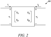
- FIG. 2 is an example illustration of a two-port model 200 for a two-element array according to a possible embodiment.
- the two ports can correspond to two antennas in an antenna array.
- i 1 and v 1 denote the current and voltage for the first antenna
- i 2 and v 2 denote the current and voltage for the second antenna.
- FIG. 3 is an example illustration of a Thevenin source model 300 according to a possible embodiment.
- FIG. 4 is an example illustration of a Norton source model 400 according to a possible embodiment.
- the two linear source models 300 and 400 can be considered for driving an antenna array.
- Thevenin source model 300 can include ideal voltage sources v s in combination with series impedances Z S_Thev
- the Norton source model 400 can include an ideal current source i s in combination with a parallel shunt impedance Z S_Nor .
- the degree of coupling will depend on the circuits used to drive the array. For example, the coupling of the transmitted symbol into adjacent elements will depend both on the mutual coupling of the antenna elements and on the source impedance associated with the Norton or Thevenin source used to drive each element of the array. Similarly, for a symbol arriving at the j-th element of the receive array, the degree to which the symbol couples into the other elements of the receive array is a function of both the mutual coupling of the antenna elements and of the impedances used to load the receive antenna array elements.
- the vector p ( ⁇ , ⁇ ) denotes the vector of antenna patterns for the M antenna elements of the eNB array when each element is measured when the other elements are open circuit.
- p i ( ⁇ , ⁇ ) is the antenna pattern for the i-th element of the eNB array when all of the other antenna elements in the eNB array are open circuit.
- the far field antenna pattern can be shown to be given by ⁇ S T Z eNB _ Thev + Z eNB ⁇ 1 p ⁇ ⁇ .
- the far-field antenna pattern is given by i S T Z eNB _ Nor ⁇ 1 + Z eNB ⁇ 1 ⁇ 1 Z eNB ⁇ 1 p ⁇ ⁇ .
- the signal observed at the j-th element of the UE array also depends on the source model used.
- An interesting question to consider is whether or not the channel observed at the j-th element of the UE array with one source model used to drive the eNB array can be determined from the channel observed with a different source model, and furthermore, whether this transformation can be determined using only the impedance parameters for the array and without knowledge of the antenna element patterns.
- Thev also depends on the impedance matrix of the of the eNB antenna array, Z eNB , this dependence has been suppressed in the notation, as Z eNB is a function of the eNB antenna array only, and is assumed to be fixed.
- H eNB ⁇ UE ; i,j From the definition of H eNB ⁇ UE ; i,j , it follows that the antenna pattern p i ⁇ ⁇ of the i -th element of the eNB array yields the channel observation H eNB ⁇ UE ; i,j at the j -th UE antenna.
- the antenna pattern corresponding to the precoder v k is given by ⁇ k T Z eNB_Thev + Z eNB ⁇ 1 p ⁇ ⁇ .
- Thev is used to denote the vector channel observed at at the UE antenna array when the elements of the UE antenna array are open circuit and when the eNB transmit array is driven by a Thevenin source with voltage source vector v k , it follows that ⁇ k T Z eNB_Thev + Z eNB ⁇ 1 p ⁇ ⁇ ⁇ F eNB ⁇ UE ; k , ⁇ Thev Z eNB_Thev .
- H eNB ⁇ UE such that p ⁇ ⁇ ⁇ H eNB ⁇ UE
- H Nor Z S_Nor
- F eNB ⁇ UE Nor Z eNB _ Nor Z eNB _ Nor ⁇ 1 + Z eNB ⁇ 1 ⁇ 1 Z eNB ⁇ 1 H eNB ⁇ UE .
- the channel observed at the UE antenna array for a given precoder depends on both: (i) whether the precoder is implemented as a Thevenin source driven by a voltage vector or a Norton source driven by a current vector; and (ii) the source impedance used.
- FIG. 5 is an example illustration of a circuit model 500 for a single receive antenna according to a possible embodiment.
- the circuit can be represented as the circuit model 500.
- v i denotes the open-circuit voltage induced on the UE receive antenna by the signal arriving from the i-th eNB antenna
- Z A denotes the self-impedance of the antenna
- the voltage across the load impedance is given by ⁇ i Z L Z A .
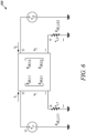
- FIG. 6 is an example illustration of a circuit model 600 for a two-element receive array according to a possible embodiment.
- the channel vector measured by an array of coupled antennas at the UE when the UE antenna array load impedance is Z UE_L As before, we consider the case of a two element array with impedance matrix Z UE as shown in the circuit model 600.
- F UE ⁇ eNB Thev Z UE_Thev and F UE ⁇ eNB Nor Z UE_Nor as the matrix channel observed at the eNB antenna array when the eNB antenna array is open circuit and when the UE transmit array is driven by a Thevenin and Norton sources, respectively
- G UE ⁇ eNB Thev Z UE_Thev Z eNB_L and G UE ⁇ eNB Nor Z UE_Nor Z eNB_L as the matrix channel measured across the load impedances at the eNB when the UE is driven by a Thevenin and Norton source, respectively.
- H UE ⁇ eNB H eNB ⁇ UE T
- the channel measurement reflects the antenna patterns of both the transmit and receive antennas.
- the matrices Z eNB and Z eNB are diagonal. Since the matrices Z eNB_Thev and Z UE_Thev are diagonal, it follows in this case the matrices needed to compute the reverse channel, Z eNB_Thev + Z eNB T Z eNB + Z eNB_L ⁇ T Z eNB_L T and Z UE_Thev + Z UE T Z UE + Z UE_L ⁇ T Z UE_L T are also diagonal, and it is only necessary to signal M values from the eNB to the UE and N values from the UE to the eNB in order for each to compute the reverse channel.
- the UE In order for the eNB to compute channel from the eNB to the UE from the measurement of the channel from the UE to the eNB, the UE should signal the diagonal N ⁇ N matrix Z UE_L to the eNB. Similarly, in order for the UE to compute the channel from the UE to the eNB from the measurement of the channel from the eNB to the UE, the eNB should signal the diagonal N ⁇ N matrix Z eNB_L to the UE. Because the matrices Z UE_L and Z eNB_L are diagonal, it is only necessary to signal N and M values should be signaled to the eNB and UE, respectively, in order for each to compute the reverse channel.
- G eNB ⁇ UE Thev Z eNB_Thev Z UE_L Z UE_L Z eNB_L ⁇ 1 G UE ⁇ eNB Thev Z UE_Thev Z eNB_L T , so that the forward and reverse channels are reciprocal within the scalar constant Z UE_L Z eNB_L ⁇ 1 .
- the scale factor is due to the fact that for the model used here, the radiated power is inversely proportional to the source impedance when the source impedance and the antenna self-impedance are matched.
- the UE In assessing the quality of the link from the UE to the eNB from measurements of the link from the eNB to the UE, the UE should account for this difference in transmit power between the two links.
- the UE in order for the eNB to compute the forward channel from the reverse channel measurement, the UE should signal the N ⁇ N matrix Z UE ⁇ 1 + Z UE_L ⁇ 1 ⁇ T to the eNB.
- the eNb in order for the UE to compute the reverse channel from the forward channel measurement, the eNb should signal the M ⁇ M matrix Z eNB ⁇ 1 + Z eNB_L ⁇ 1 ⁇ T to the UE.
- the impedance matrices Z eNB and Z UE are diagonal (no coupling in the eNB and UE arrays)
- the matrices Z UE ⁇ 1 + Z UE_L ⁇ 1 ⁇ T and Z eNB ⁇ 1 + Z eNB_L ⁇ 1 ⁇ T are diagonal.
- the measured channels are reciprocal within a multiplicative constant so long as there is no mutual coupling of the antennas at the eNB array or the UE array.
- the multiplicative constant is the ratio of the harmonic mean of the load impedance and the antenna self-impedance for the UE to that of the harmonic mean of the load impedance and antenna self-impedance for the eNB.
- H UE ⁇ eNB H eNB ⁇ UE T
- G eNB ⁇ UE Nor Z eNB_Nor Z UE_L Z eNB_Nor ⁇ 1 Z eNB ⁇ 1 ⁇ 1 Z eNB ⁇ 1 H eNB ⁇ UE Z UE + Z UE_L ⁇ T Z UE_L T
- G UE ⁇ eNB Nor Z UE_Nor Z eNB_L Z UE_Nor ⁇ 1 + Z UE ⁇ 1 ⁇ 1 Z UE ⁇ 1 H eNB ⁇ UE T Z eNB + Z eNB_L ⁇ T Z eNB_L T
- the UE has knowledge of its own impedance matrix Z UE , transmit source impedance Z UE_Nor , and receive load impedance Z UE_L , and can compute Z UE_Nor ⁇ 1 + Z UE ⁇ 1 ⁇ 1 Z UE ⁇ 1 Z UE + Z UE_L Z UE_L ⁇ 1 .
- the eNB measures G UE ⁇ eNB Nor Z UE_Nor Z eNB_L using reference symbols transmitted from the UE.
- the matrices Z eNB and Z UE are diagonal. Since the matrices Z eNB_Nor and Z UE_Nor are diagonal, it follows in this case the matrices needed to calculate the reverse channel, Z eNB_Nor ⁇ 1 + Z eNB ⁇ 1 T Z eNB T Z eNB + Z eNB_L ⁇ T Z eNB_L T and Z UE_Nor ⁇ 1 + Z UE ⁇ 1 T Z UE T Z UE + Z UE_L ⁇ T Z UE_L T are also diagonal and it is only necessary to signal M values from the eNB to the UE and N values from the UE to the eNB.
- the UE in order for the eNB to compute the forward channel from the reverse channel measurement, the UE should signal the N ⁇ N matrix Z UE + Z UE_L ⁇ T Z UE_L T to the eNB.
- the eNB in order for the UE to compute the reverse channel from the forward channel measurement, the eNB should signal the M ⁇ M matrix Z eNB + Z eNB_L ⁇ T Z eNB_L T to the UE.
- the impedance matrices Z eNB and Z UE are diagonal (no coupling in the eNB and UE arrays)
- the matrices Z UE + Z UE_L ⁇ T Z UE_L T and Z eNB + Z eNB_L ⁇ T Z eNB_L T are diagonal so that the number of coefficients which should be signaled is N and M , respectively.
- G eNB ⁇ UE Nor Z eNB _ Nor ⁇ ⁇ ⁇ I M ⁇ M , Z UE _ L Z eNB _ L Z eNB + Z eNB _ L ⁇ 1 Z UE _ L Z UE + Z UE _ L G UE ⁇ eNB Nor Z UE _ Nor ⁇ ⁇ ⁇ I N ⁇ N , Z eNB _ L T .
- the measured channels are reciprocal within a multiplicative constant so long as there is no mutual coupling of the antennas at the eNB array or the UE array.
- Thevenin source at the eNB and a Norton source at the UE as well as for a Norton source at the UE and a Thevenin source at the eNB, the analysis can be similar to that described above.
- the forward and reverse channels have the relationship G UE ⁇ eNB
- the eNB In order for the UE to compute the UE to eNB channel from its measurement of G eNB ⁇ UE Thev Z eNB _ Thev Z UE _ L , and its presumed knowledge of Z UE _ Thev + Z UE ⁇ 1 Z UE + Z UE _ L Z UE _ L ⁇ 1 , the eNB should signal the M ⁇ M matrix Z eNB _ Thev + Z eNB T Z eNB + Z eNB _ L ⁇ T Z eNB _ L T to the UE.
- the UE should signal the N ⁇ N matrix Z UE_Thev + Z UE T Z UE + Z UE_L ⁇ T Z UE_L T to the eNB.
- the channel from the UE to the eNB can be expressed as G UE ⁇ eNB
- Thev Z UE_Thev Z eNB_L Z UE_Thev + Z UE ⁇ 1 Z UE + Z UE_L Z UE_L ⁇ 1 ⁇ Z eNB_L Z eNB + Z eNB_L ⁇ 1 Z eNB_Thev + Z eNB G eNB ⁇ UE Thev Z eNB_Thev Z UE_L T .
- the UE measurement will be Z eNB_L Z eNB + Z eNB_L ⁇ 1 Z eNB_Thev + Z eNB G eNB ⁇ UE Thev Z eNB_Thev Z UE_L , so that the UE no longer needs explicit knowledge of the eNB coupling in order to compute the UE to eNB channel since it is no longer necessary to correct the measured channel for the difference between the eNB transmitter and the eNB receiver.
- the UE measurement will be Z UE_L Z UE + Z UE_L ⁇ 1 Z UE_Thev + Z UE G UE ⁇ eNB Thev Z UE_Thev Z eNB_L , so that the eNB no longer needs explicit knowledge of the UE coupling in order to compute the eNB to UE channel since it is no longer necessary to correct the measured channel for the difference between the UE transmitter and the UE receiver.
- the eNB should signal the M ⁇ M matrix Z eNB_Nor ⁇ 1 + Z eNB ⁇ 1 T Z eNB T Z eNB + Z eNB_L ⁇ T Z eNB_L T to the UE.
- the UE should signal the N ⁇ N matrix Z UE_Nor ⁇ 1 + Z UE ⁇ 1 T Z UE T Z UE + Z UE_L ⁇ T Z UE_L T to the eNB.
- the UE measurement will be Z eNB_L Z eNB + Z eNB_L ⁇ 1 Z eNB Z eNB_Nor ⁇ 1 + Z eNB ⁇ 1 G eNB ⁇ UE Nor Z eNB_Nor Z UE_L , so that the UE no longer needs explicit knowledge of the eNB coupling in order to compute the UE to eNB channel since it is no longer necessary to correct the measured channel for the difference between the eNB transmitter and the eNB receiver.
- the UE measurement will be Z UE _ L Z UE + Z UE _ L ⁇ 1 Z UE Z UE _ Nor ⁇ 1 + Z UE ⁇ 1 G UE ⁇ eNB Nor Z UE _ Nor Z eNB _ L , so that the eNB no longer needs explicit knowledge of the UE coupling in order to compute the eNB to UE channel since it is no longer necessary to correct the measured channel for the difference between the UE transmitter and the UE receiver.
- G eNB ⁇ UE general denote the end-to-end channel, including antenna coupling, as measured at the UE
- G UE ⁇ eNB general denote the end-to-end channel, including antenna coupling, measured at the eNB.
- eNB the has knowledge of the transmit and receive coupling for the eNB, given by A TX and A RX , respectively.
- the UE has knowledge of the transmit and receive coupling for the UE, given by B TX and B RX , respectively.
- a Thevenin and Norton source were used at both the eNB and the UE, there are essentially two methods that can be used to enable the UE to learn G UE ⁇ eNB general .
- the eNB signals the M ⁇ M matrix ( A TX ) -T ( A RX ) T to the UE.
- the vector input to the eNB array is multiplied by A RX ( A TX ) - 1 when reference symbols are transmitted.
- the UE measures the channel A RX A TX ⁇ 1 G eNB ⁇ UE general and thus there is no need to explicitly signal ( A TX ) - T ( A RX ) T to the UE as this is incorporated in the channel measurement.
- the UE signals the N ⁇ N matrix ( B TX ) - T ( B RX ) T to the eNB.
- the vector input to the UE array is multiplied by B RX ( B TX ) -1 when reference symbols are transmitted.
- the eNB then measures the channel B RX B TX ⁇ 1 G UE ⁇ eNB general and thus there is no need to explicitly signal B RX ( B TX ) -1 to the eNB as this is incorporated in the channel measurement.
- FIG. 7 is an example flowchart 700 illustrating the operation of a receiving device, such as the receiving device 110, according to a possible embodiment. At 710, the flowchart 700 can begin.
- a signal based on a first product of an inverse transpose of a transmit coupling matrix of a transmitting device and a transpose of a receive coupling matrix of the transmitting device can be received at the receiving device.
- the transmit coupling matrix of the transmitting device can be based on a source impedance matrix of a transmitter at the transmitting device and an impedance matrix of an array of antennas at the transmitting device.
- the receive coupling matrix of the transmitting device can be based on a load impedance of a receiver at the transmitting device and an impedance matrix of an array of antennas at the transmitting device.
- the first product of a transpose inverse of a transmit coupling matrix of the transmitting device and a transpose receive coupling matrix of the transmitting device can be based on: Z UE_Thev + Z UE T Z UE + Z UE_L ⁇ T Z UE_L T or Z UE_Nor ⁇ 1 + Z UE ⁇ 1 T Z UE T Z UE + Z UE_L ⁇ T Z UE_L T .
- These examples reference a UE as the transmitting device, but can also apply to an eNB or other transmitting device.
- the signal based on the first product can include data comprising the first product of the inverse transpose of the transmit coupling matrix of the transmitting device and a transpose of the receive coupling matrix of the transmitting device.
- the transmitting device can send the first product as data.
- the signal based on the first product can include reference symbols multiplied by a transpose of the first product of the transpose inverse of the transmit coupling matrix of the transmitting device and the transpose of the receive coupling matrix of the transmitting device.
- a second product of a transmit coupling matrix of the receiving device and an inverse of a receive coupling matrix of the receiving device can be calculated.
- the transmit coupling matrix of the receiving device can be based on a source impedance matrix of a transmitter at the receiving device and an impedance matrix of an array of antennas at the receiving device.
- the receive coupling matrix of the receiving device can be based on a load impedance of a receiver at the receiving device and an impedance matrix of an array of antennas at the receiving device.
- a receive channel from the transmitting device to the receiving device using reference symbols transmitted by the transmitting device can be measured.
- a reverse channel can be determined based on the signal and based on a third product of the second product and the measurement of the receive channel.
- the reverse channel can be determined based on a third product of the second product, the measurement of the receive channel, and the first product of the transpose inverse of the transmit coupling matrix of the transmitting device and the transpose of the receive coupling matrix of the transmitting device.
- the transpose inverse of the first product of the transmit coupling matrix of the transmitting device and the transpose of the receive coupling matrix of the transmitting device can be determined at the transmitting device and sent as data to save bandwidth by not requiring data for both matrices.
- the both matrices can be sent as data and the first product of the transpose inverse of the transmit coupling matrix of the transmitting device and the transpose of the receive coupling matrix of the transmitting device can be determined at the receiving device.
- a precoding matrix can be generated based on the reverse channel.
- a signal can be received for transmission.
- the signal can be received from other elements in the receiving device.
- the precoding matrix can be applied to the signal to generate a precoded signal for transmission over a physical channel.
- the precoded signal based on the reverse channel can be transmitted.
- the flowchart 700 can end.
- FIG. 8 is an example block diagram of an apparatus 800, such as the device 110 or the device 120, according to a possible embodiment.
- the apparatus 800 can include a housing 810, a controller 820 within the housing 810, audio input and output circuitry 830 coupled to the controller 820, a display 840 coupled to the controller 820, a transceiver 850 coupled to the controller 820, a plurality of antennas 855 and 857, such as an array of antennas, coupled to the transceiver 850, a user interface 860 coupled to the controller 820, a memory 870 coupled to the controller 820, and a network interface 880 coupled to the controller 820.
- the apparatus 800 can also include additional elements or less elements depending on the device in which it is implemented.
- the apparatus 800 can perform the methods described in all the embodiments.
- the display 840 can be a viewfinder, a liquid crystal display (LCD), a light emitting diode (LED) display, a plasma display, a projection display, a touch screen, or any other device that displays information.
- the transceiver 850 can include a transmitter and/or a receiver.
- the transceiver 850 can also include a plurality of transceivers with each transceiver coupled a corresponding antenna of the plurality of antennas 855 and 857.
- the audio input and output circuitry 830 can include a microphone, a speaker, a transducer, or any other audio input and output circuitry.
- the user interface 860 can include a keypad, a keyboard, buttons, a touch pad, a joystick, a touch screen display, another additional display, or any other device useful for providing an interface between a user and an electronic device.
- the network interface 880 can be a Universal Serial Bus (USB) port, an Ethernet port, an infrared transmitter/receiver, an IEEE 1398 port, a WLAN transceiver, or any other interface that can connect an apparatus to a network, device, or computer and that can transmit and receive data communication signals.
- the memory 870 can include a random access memory, a read only memory, an optical memory, a flash memory, a removable memory, a hard drive, a cache, or any other memory that can be coupled to a wireless communication device.
- the plurality of antennas 855 and 857 can be considered a transmitter array of antennas when the transceiver 850 is transmitting signals.
- the transmitter array of antennas 855 and 857 can include two or more antennas.
- the transmitter array of antennas 855 and 857 can be mutually coupled in that one of a voltage and current applied to one antenna element induces a voltage or current on another antenna element in the transmitter array of antennas 855 and 857.
- the apparatus 800 or the controller 820 may implement any operating system, such as Microsoft Windows ® , UNIX ® , or LINUXOO , Android TM , or any other operating system.
- Apparatus operation software may be written in any programming language, such as C, C++, Java or Visual Basic, for example.
- Apparatus software may also run on an application framework, such as, for example, a Java ® framework, a .NET ® framework, or any other application framework.
- the software and/or the operating system may be stored in the memory 870 or elsewhere on the apparatus 800.
- the apparatus 800 or the controller 820 may also use hardware to implement disclosed operations.
- the controller 820 may be any programmable processor.
- Disclosed embodiments may also be implemented on a general-purpose or a special purpose computer, a programmed microprocessor or microprocessor, peripheral integrated circuit elements, an application-specific integrated circuit or other integrated circuits, hardware/electronic logic circuits, such as a discrete element circuit, a programmable logic device, such as a programmable logic array, field programmable gate-array, or the like.
- the controller 820 may be any controller or processor device or devices capable of operating a communication device and implementing the disclosed embodiments.
- the transceiver 850 can receive a signal based on a first product of an inverse transpose of a transmit coupling matrix of a transmitting device and a transpose of a receive coupling matrix of the transmitting device.
- the transmit coupling matrix of the transmitting device can be based on a source impedance matrix of a transmitter at the transmitting device and an impedance matrix of an array of antennas at the transmitting device.
- the receive coupling matrix of the transmitting device can be based on a load impedance of a receiver at the transmitting device and an impedance matrix of an array of antennas at the transmitting device.
- the signal can include data comprising the first product of the inverse transpose of the transmit coupling matrix of the transmitting device and a transpose of the receive coupling matrix of the transmitting device.
- the controller 820 can determine the determined receive channel based on a third product of the second product, the measurement of the receive channel, and the first product of the transpose inverse of the transmit coupling matrix of the transmitting device and the transpose of the receive coupling matrix of the transmitting device.
- the signal can also include reference symbols multiplied by a transpose of the first product of the transpose inverse of the transmit coupling matrix of the transmitting device and the transpose of the receive coupling matrix of the transmitting device.
- the controller 820 can calculate a second product of a transmit coupling matrix of the apparatus 800 and an inverse of a receive coupling matrix of the apparatus 800.
- the transmit coupling matrix of the apparatus 800 and the receive coupling matrix of the apparatus 800 can be based on the plurality of antennas 855 and 857.
- the transmit coupling matrix of the apparatus 800 can be based on a source impedance matrix of a transmitter at the apparatus and an impedance matrix of the plurality of antennas at the apparatus.
- the receive coupling matrix of the apparatus 800 can be based on a load impedance of a receiver at the apparatus and an impedance matrix of the plurality of antennas at the apparatus.
- the controller 820 can measure a receive channel from the transmitting device to the apparatus using reference symbols transmitted by the transmitting device.
- the controller 820 can determine a reverse channel based on the signal and based on a third product of the second product and the measurement of the receive channel.
- the controller 820 can generate a precoding matrix based on the reverse channel, can receive a signal for transmission, and can apply the precoding matrix to the signal to generate a precoded signal for transmission over a physical channel.
- the transceiver 850 can transmit the precoded signal based on the reverse channel.
- the controller 820 can calculate a first product of an inverse of a transmit coupling matrix of the apparatus 800 and a receive coupling matrix of the apparatus 800.
- the first product of the inverse of transmit coupling matrix of the apparatus 800 and the receive coupling matrix of the apparatus 800 can be determined as described in the above embodiments.
- the signal can be based on the first product can include data comprising the first product of the inverse of the transmit coupling matrix of the apparatus 800 and the receive coupling matrix of the apparatus 800.
- the signal based on the first product can also comprise reference symbols multiplied by a first product of the inverse of the transmit coupling matrix of the apparatus 800 and the receive coupling matrix of the apparatus 800.
- the transceiver 850 can then transmit the signal based on the first product of an inverse of the transmit coupling matrix of the apparatus 800 and the receive coupling matrix of the apparatus 800 to a receiving device.
- the method of this disclosure can be implemented on a programmed processor.
- the controllers, flowcharts, and modules may also be implemented on a general purpose or special purpose computer, a programmed microprocessor or microcontroller and peripheral integrated circuit elements, an integrated circuit, a hardware electronic or logic circuit such as a discrete element circuit, a programmable logic device, or the like.
- any device on which resides a finite state machine capable of implementing the flowcharts shown in the figures may be used to implement the processor functions of this disclosure.
Landscapes
- Engineering & Computer Science (AREA)
- Signal Processing (AREA)
- Computer Networks & Wireless Communication (AREA)
- Physics & Mathematics (AREA)
- Electromagnetism (AREA)
- Power Engineering (AREA)
- Variable-Direction Aerials And Aerial Arrays (AREA)
- Radio Transmission System (AREA)
- Transmitters (AREA)
Claims (6)
- Verfahren, umfassend:Empfangen (715), an einer Empfangsvorrichtung, eines Signals, das Daten einschließt, die ein erstes Produkt aus einer inversen Transponierung einer Übertragungskopplungsmatrix einer Übertragungsvorrichtung und einer Transponierung einer Empfangskopplungsmatrix der Übertragungsvorrichtung umfassen, wobei die Übertragungskopplungsmatrix der Übertragungsvorrichtung auf einer Quellenimpedanzmatrix eines Senders an der Übertragungsvorrichtung und einer Impedanzmatrix einer Anordnung von Antennen an der Übertragungsvorrichtung basiert und die Empfangskopplungsmatrix der Übertragungsvorrichtung auf einer Lastimpedanz eines Empfängers an der Übertragungsvorrichtung und einer Impedanzmatrix einer Anordnung von Antennen an der Übertragungsvorrichtung basiert;Berechnen (720) eines zweiten Produkts aus einer Übertragungskopplungsmatrix der Empfangsvorrichtung und einer Invertierung einer Empfangskopplungsmatrix der Empfangsvorrichtung, wobei die Übertragungskopplungsmatrix der Empfangsvorrichtung auf einer Quellenimpedanzmatrix eines Senders an der Empfangsvorrichtung und einer Impedanzmatrix einer Anordnung von Antennen an der Empfangsvorrichtung basiert und die Empfangskopplungsmatrix der Empfangsvorrichtung auf einer Lastimpedanz eines Empfängers an der Empfangsvorrichtung und einer Impedanzmatrix einer Anordnung von Antennen an der Empfangsvorrichtung basiert;Messen (725), an der Empfangsvorrichtung, eines Empfangskanals zwischen der Übertragungsvorrichtung und der Empfangsvorrichtung unter Verwendung von Referenzsymbolen, die von der Übertragungsvorrichtung empfangen werden;Bestimmen (730) eines Rückwärtskanals basierend auf dem Signal, dem zweiten Produkt und der Messung des Empfangskanals; undÜbertragen (750) eines vorcodierten Signals basierend auf dem Rückwärtskanal.
- Verfahren nach Anspruch 1, ferner umfassend:Erzeugen (735) einer Vorcodierungsmatrix basierend auf dem Rückwärtskanal;Empfangen (740) eines Signals zur Übertragung; undAnwenden (745) der Vorcodierungsmatrix auf das Signal, um das vorcodierte Signal zur Übertragung über einen physischen Kanal zu erzeugen.
- Verfahren nach Anspruch 1, wobei das Bestimmen das Bestimmen des Rückwärtskanals basierend auf einem dritten Produkt aus dem zweiten Produkt, der Transponierung der Messung des Empfangskanals und der Transponierung des ersten Produkts umfasst.
- Einrichtung, umfassend Mittel zum Durchführen des Verfahrens nach einem der Ansprüche 1 bis 3.
- Verfahren, umfassend:Berechnen, an einer Übertragungsvorrichtung, eines ersten Produkts aus einer inversen Transponierung einer Übertragungskopplungsmatrix der Übertragungsvorrichtung und einer Transponierung einer Empfangskopplungsmatrix der Übertragungsvorrichtung, wobei die Übertragungskopplungsmatrix der Übertragungsvorrichtung auf einer Quellenimpedanzmatrix eines Senders an der Übertragungsvorrichtung und einer Impedanzmatrix einer Anordnung von Antennen an der Übertragungsvorrichtung basiert und die Empfangskopplungsmatrix der Übertragungsvorrichtung auf einer Lastimpedanz eines Empfängers an der Übertragungsvorrichtung und einer Impedanzmatrix einer Anordnung von Antennen an der Übertragungsvorrichtung basiert;Übertragen, zu einer Empfangsvorrichtung, eines Signals, das Daten einschließt, die das erste Produkt umfassen;Übertragen, zu der Empfangsvorrichtung, von Referenzsymbolen zum Messen eines Empfangskanals zwischen der Übertragungsvorrichtung und der Empfangsvorrichtung durch die Empfangsvorrichtung; undEmpfangen, von der Empfangsvorrichtung, eines vorcodierten Signals basierend auf einem Rückwärtskanal,wobei der Rückwärtskanal durch die Empfangsvorrichtung basierend auf dem Signal, einem zweiten Produkt aus einer Übertragungskopplungsmatrix der Empfangsvorrichtung und einer Inversen einer Empfangskopplungsmatrix der Empfangsvorrichtung und der Messung des Empfangskanals bestimmt wird,wobei die Übertragungskopplungsmatrix der Empfangsvorrichtung auf einer Quellenimpedanzmatrix eines Senders an der Empfangsvorrichtung und einer Impedanzmatrix einer Anordnung von Antennen an der Empfangsvorrichtung basiert und die Empfangskopplungsmatrix der Empfangsvorrichtung auf einer Lastimpedanz eines Empfängers an der Empfangsvorrichtung und einer Impedanzmatrix einer Anordnung von Antennen an der Empfangsvorrichtung basiert undwobei das zweite Produkt durch die Empfangsvorrichtung berechnet wird.
- Einrichtung, umfassend Mittel zum Durchführen des Verfahrens nach Anspruch 5.
Applications Claiming Priority (3)
| Application Number | Priority Date | Filing Date | Title |
|---|---|---|---|
| US201562209405P | 2015-08-25 | 2015-08-25 | |
| US14/933,459 US10148327B2 (en) | 2015-08-25 | 2015-11-05 | Method and apparatus for channel determination for time division duplex systems with coupled antennas |
| PCT/US2016/058488 WO2017078957A1 (en) | 2015-11-05 | 2016-10-24 | Method and apparatus for channel determination for time division duplex systems with coupled antennas |
Publications (3)
| Publication Number | Publication Date |
|---|---|
| EP3342060A1 EP3342060A1 (de) | 2018-07-04 |
| EP3342060B1 true EP3342060B1 (de) | 2023-12-13 |
| EP3342060C0 EP3342060C0 (de) | 2023-12-13 |
Family
ID=58096903
Family Applications (2)
| Application Number | Title | Priority Date | Filing Date |
|---|---|---|---|
| EP16791200.5A Active EP3342062B1 (de) | 2015-08-25 | 2016-10-21 | Verfahren und vorrichtung zur strahlformung mit gekoppelten antennen |
| EP16788400.6A Active EP3342060B1 (de) | 2015-08-25 | 2016-10-24 | Verfahren und vorrichtung zur kanalbestimmung für zeitduplexsysteme mit gekoppelten antennen |
Family Applications Before (1)
| Application Number | Title | Priority Date | Filing Date |
|---|---|---|---|
| EP16791200.5A Active EP3342062B1 (de) | 2015-08-25 | 2016-10-21 | Verfahren und vorrichtung zur strahlformung mit gekoppelten antennen |
Country Status (4)
| Country | Link |
|---|---|
| US (3) | US9590708B1 (de) |
| EP (2) | EP3342062B1 (de) |
| CN (2) | CN108352880B (de) |
| WO (1) | WO2017034851A1 (de) |
Families Citing this family (15)
| Publication number | Priority date | Publication date | Assignee | Title |
|---|---|---|---|---|
| US9590708B1 (en) * | 2015-08-25 | 2017-03-07 | Motorola Mobility Llc | Method and apparatus for equal energy codebooks for antenna arrays with mutual coupling |
| US10218067B2 (en) | 2015-09-04 | 2019-02-26 | Elwha Llc | Tunable metamaterial systems and methods |
| US10236576B2 (en) | 2015-09-04 | 2019-03-19 | Elwha Llc | Wireless power transfer using tunable metamaterial systems and methods |
| US11201647B2 (en) * | 2016-08-11 | 2021-12-14 | Motorola Mobility Llc | Method and apparatus for equal energy codebooks for coupled antennas with transmission lines |
| US10374669B2 (en) | 2016-08-31 | 2019-08-06 | Elwha Llc | Tunable medium linear coder |
| US9941999B1 (en) * | 2017-03-08 | 2018-04-10 | Allegro Microsystems, Llc | Methods and apparatus for communication over an isolation barrier with monitoring |
| US10468776B2 (en) * | 2017-05-04 | 2019-11-05 | Elwha Llc | Medical applications using tunable metamaterial systems and methods |
| US20180368104A1 (en) * | 2017-06-14 | 2018-12-20 | Futurewei Technologies, Inc. | System and Method for Indicating Scheduling Grants |
| KR102373485B1 (ko) * | 2017-08-25 | 2022-03-11 | 삼성전자주식회사 | 무선 통신 시스템에서 채널 피드백을 위한 장치 및 방법 |
| US10249950B1 (en) | 2017-09-16 | 2019-04-02 | Searete Llc | Systems and methods for reduced control inputs in tunable meta-devices |
| US10833381B2 (en) | 2017-11-08 | 2020-11-10 | The Invention Science Fund I Llc | Metamaterial phase shifters |
| US10516452B1 (en) * | 2018-06-08 | 2019-12-24 | University Of South Florida | Using artificial signals to maximize capacity and secrecy of multiple-input multiple-output (MIMO) communication |
| US10644771B2 (en) * | 2018-06-08 | 2020-05-05 | University Of South Florida | Using artificial signals to maximize capacity and secrecy of multiple-input multiple-output (MIMO) communication |
| US11115244B2 (en) | 2019-09-17 | 2021-09-07 | Allegro Microsystems, Llc | Signal isolator with three state data transmission |
| KR102765427B1 (ko) | 2020-11-02 | 2025-02-12 | 삼성전자주식회사 | 무선 통신 시스템에서 빔포머를 제어하기 위한 장치 및 방법 |
Family Cites Families (42)
| Publication number | Priority date | Publication date | Assignee | Title |
|---|---|---|---|---|
| JP2005502250A (ja) * | 2001-08-31 | 2005-01-20 | ザ トラスティーズ オブ コロムビア ユニバーシティ イン ザ シティ オブ ニューヨーク | 相互結合されたパッチに最適パッチアンテナ励振を与えるシステム及び方法 |
| US7181246B2 (en) * | 2002-06-05 | 2007-02-20 | Neocific, Inc. | Adaptive communications system and method |
| US8134976B2 (en) * | 2002-10-25 | 2012-03-13 | Qualcomm Incorporated | Channel calibration for a time division duplexed communication system |
| US7457590B2 (en) | 2003-12-23 | 2008-11-25 | Motorola, Inc. | Method, apparatus and system for use in the transmission of wireless communications using multiple antennas |
| US7206354B2 (en) * | 2004-02-19 | 2007-04-17 | Qualcomm Incorporated | Calibration of downlink and uplink channel responses in a wireless MIMO communication system |
| WO2006052890A1 (en) * | 2004-11-05 | 2006-05-18 | University Of Florida Research Foundation, Inc. | Uniform channel decomposition for mimo communications |
| US8307922B2 (en) * | 2005-05-24 | 2012-11-13 | Rearden, Llc | System and method for powering an aircraft using radio frequency signals and feedback |
| US7551907B2 (en) * | 2005-09-02 | 2009-06-23 | Sigma Designs, Inc. | Digital automatic gain control with parallel/serial interface for multiple antenna ultra wideband OFDM system |
| US7804917B2 (en) * | 2005-11-07 | 2010-09-28 | Sigma Designs, Inc. | Clear channel assessment method and system for ultra wideband OFDM |
| US7995670B2 (en) * | 2006-05-24 | 2011-08-09 | Samsung Electronics Co., Ltd. | Method of transmitting and receiving data using precoding codebook in multi-user MIMO communication system and transmitter and receiver using the method |
| US8396158B2 (en) * | 2006-07-14 | 2013-03-12 | Nokia Corporation | Data processing method, data transmission method, data reception method, apparatus, codebook, computer program product, computer program distribution medium |
| US7702029B2 (en) * | 2006-10-02 | 2010-04-20 | Freescale Semiconductor, Inc. | MIMO precoding enabling spatial multiplexing, power allocation and adaptive modulation and coding |
| FR2909240A1 (fr) * | 2006-11-24 | 2008-05-30 | France Telecom | Procedes et modules d'emission/reception pour un systeme multi-antennes multi-porteuses a sequence d'apprentissage. |
| US7953138B2 (en) * | 2007-01-09 | 2011-05-31 | Broadcom Corporation | Method and system for an efficient channel quantization method for MIMO pre-coding systems |
| WO2009106090A1 (en) * | 2008-02-25 | 2009-09-03 | Telefonaktiebolaget Lm Ericsson (Publ) | A method of and a device for precoding transmit data signals in a wireless mimo communication system |
| US8009598B2 (en) * | 2008-04-08 | 2011-08-30 | Mstar Semiconductor, Inc. | Method and system of radio resource allocation for mobile MIMO-OFDMA |
| US8498358B2 (en) * | 2008-04-25 | 2013-07-30 | Samsung Electronics Co., Ltd. | Multiple antenna communication system including adaptive updating and changing of codebooks |
| US8204470B2 (en) * | 2009-01-06 | 2012-06-19 | Texas Instruments Incorporated | Predecoding for joint processing coordinated multi-point transmission |
| KR101524284B1 (ko) * | 2009-03-27 | 2015-05-29 | 삼성전자주식회사 | 중계 방식의 무선통신 시스템에서 양방향 중계를 위한 장치및 방법 |
| EP2448137A1 (de) | 2009-06-23 | 2012-05-02 | Alcatel Lucent | Verfahren und vorrichtung zur signalübertragung in einem mimo-zeitduplexsystem |
| FR2950760B1 (fr) * | 2009-09-28 | 2012-02-10 | Excem | Procede de transmission utilisant une interconnexion non uniforme |
| KR20110093379A (ko) * | 2010-02-12 | 2011-08-18 | 주식회사 팬택 | 채널상태정보 피드백 장치와 그 방법, 기지국, 그 기지국의 전송방법 |
| US20120314563A1 (en) * | 2010-02-12 | 2012-12-13 | Qinglin Luo | Device and method for calibrating reciprocity errors |
| KR101403154B1 (ko) * | 2010-04-27 | 2014-06-03 | 후지쯔 가부시끼가이샤 | 무선 통신 방법, 무선 기지국, 이동 단말기, 무선 통신 시스템 |
| CN101873203B (zh) * | 2010-06-01 | 2013-05-29 | 北京邮电大学 | Mimo中继系统中基于码书预编码的信号发送方法 |
| KR101754669B1 (ko) * | 2010-07-29 | 2017-07-06 | 엘지전자 주식회사 | 무선 통신 시스템에서 프리코딩된 신호 송수신 방법 및 장치 |
| US8442145B2 (en) * | 2010-12-03 | 2013-05-14 | Industrial Technology Research Institute | Transmitting terminal and transmit antenna selecting method thereof |
| CN103299558B (zh) * | 2011-01-07 | 2016-07-06 | 交互数字专利控股公司 | 无线发射/接收单元和由无线发射/接收单元执行的方法 |
| CN102624496B (zh) * | 2011-01-30 | 2015-03-11 | 华为技术有限公司 | 预编码处理方法、基站和通信系统 |
| CA2826243C (en) * | 2011-02-01 | 2016-06-21 | Research In Motion Limited | Mixed rank downlink compound multi-user interference alignment scheme |
| EP2671332B1 (de) * | 2011-02-01 | 2019-10-23 | BlackBerry Limited | Schema zur ausrichtung von interferenzen für mehrere benutzer einer mischrang-downlink-verbindung |
| CN102651676B (zh) * | 2011-02-24 | 2015-01-21 | 华为技术有限公司 | 预编码矩阵的确定方法及装置 |
| CN103249080B (zh) | 2012-02-03 | 2016-03-30 | 中国移动通信集团公司 | 一种确定基站的天线校准系数的方法、系统以及装置 |
| US9294179B2 (en) * | 2012-02-07 | 2016-03-22 | Google Technology Holdings LLC | Gain normalization correction of PMI and COI feedback for base station with antenna array |
| CN103378886B (zh) * | 2012-04-13 | 2016-10-05 | 中国移动通信集团公司 | 一种rru天线校准方法、装置及系统 |
| CN104025526B (zh) * | 2012-08-31 | 2017-10-10 | 日电(中国)有限公司 | 用于天线校准的方法和装置 |
| CN103812540B (zh) * | 2012-11-12 | 2017-06-27 | 华为技术有限公司 | 阵列天线及发射接收信号方法、装置 |
| CN104871437B (zh) * | 2012-12-31 | 2017-12-15 | 上海贝尔股份有限公司 | Fdd系统中信道互易性补偿方法和装置 |
| CN103152086B (zh) * | 2013-02-05 | 2016-02-10 | 上海交通大学 | 双向多中继系统中继端波束成形的鲁棒性信号处理方法 |
| WO2014146260A1 (zh) * | 2013-03-20 | 2014-09-25 | 华为技术有限公司 | 混合组网中数据的发送方法、装置和系统 |
| WO2017078957A1 (en) * | 2015-11-05 | 2017-05-11 | Motorola Mobility Llc | Method and apparatus for channel determination for time division duplex systems with coupled antennas |
| US9590708B1 (en) * | 2015-08-25 | 2017-03-07 | Motorola Mobility Llc | Method and apparatus for equal energy codebooks for antenna arrays with mutual coupling |
-
2015
- 2015-09-16 US US14/855,693 patent/US9590708B1/en active Active
- 2015-11-05 US US14/933,459 patent/US10148327B2/en active Active
- 2015-11-05 US US14/933,499 patent/US9660708B1/en active Active
-
2016
- 2016-08-16 WO PCT/US2016/047117 patent/WO2017034851A1/en not_active Ceased
- 2016-10-21 EP EP16791200.5A patent/EP3342062B1/de active Active
- 2016-10-21 CN CN201680064297.5A patent/CN108352880B/zh active Active
- 2016-10-24 CN CN201680064621.3A patent/CN108352872B/zh active Active
- 2016-10-24 EP EP16788400.6A patent/EP3342060B1/de active Active
Also Published As
| Publication number | Publication date |
|---|---|
| US10148327B2 (en) | 2018-12-04 |
| CN108352872A (zh) | 2018-07-31 |
| US9660708B1 (en) | 2017-05-23 |
| EP3342062A1 (de) | 2018-07-04 |
| CN108352880A (zh) | 2018-07-31 |
| US9590708B1 (en) | 2017-03-07 |
| EP3342060C0 (de) | 2023-12-13 |
| CN108352872B (zh) | 2022-07-19 |
| CN108352880B (zh) | 2022-05-24 |
| US20170134077A1 (en) | 2017-05-11 |
| US20170134078A1 (en) | 2017-05-11 |
| US20170063439A1 (en) | 2017-03-02 |
| WO2017034851A1 (en) | 2017-03-02 |
| EP3342062B1 (de) | 2019-12-11 |
| EP3342060A1 (de) | 2018-07-04 |
Similar Documents
| Publication | Publication Date | Title |
|---|---|---|
| EP3342060B1 (de) | Verfahren und vorrichtung zur kanalbestimmung für zeitduplexsysteme mit gekoppelten antennen | |
| JP4494462B2 (ja) | Mimo通信システムにおける送信チェーン及び受信チェーンの校正 | |
| EP3284186B1 (de) | Verfahren und vorrichtung zur optimierung der antennenvorcodiererauswahl mit gekoppelten antennen | |
| EP3323206B1 (de) | Verfahren und vorrichtung für gleiche energiecodebücher für antennenarrays mit gegenseitiger kopplung | |
| JP2012531132A (ja) | 時分割多元接続mimoシステムにおいて信号を送信する方法および関連の装置 | |
| WO2017136292A1 (en) | Method and apparatus for optimizing antenna precoder selection with coupled antennas | |
| CN110212952B (zh) | 确定用于视距mimo通信的参数和条件的方法和装置 | |
| US20180152227A1 (en) | Method and apparatus for determining parameters and conditions for line of sight mimo communication | |
| US12184344B2 (en) | UE aided antenna calibration | |
| EP3479496B1 (de) | Verfahren und vorrichtung für codebücher mit gleicher energy für mit einer übertragungsleitung gekoppelten antennen | |
| CN106685623A (zh) | 一种时延补偿方法、用户设备及基站 | |
| KR102437789B1 (ko) | 결합된 안테나들로 안테나 프리코더 선택을 최적화하기 위한 방법 및 장치 | |
| US11705976B2 (en) | Beamforming calibration | |
| WO2017078957A1 (en) | Method and apparatus for channel determination for time division duplex systems with coupled antennas | |
| CN106788639A (zh) | 一种大规模通道的硬件校正方法 | |
| WO2024069312A1 (en) | Apparatus and method of generating an evm for mimo transmission | |
| WO2024069304A1 (en) | Apparatus and method of generating an evm for mimo transmission | |
| CN109565309A (zh) | 用于获得上行链路校准值的方法、校准方法以及对应终端和基站 | |
| Zhu et al. | Interconnection Strategies for Self-Calibration of Large Scale Antenna Arrays |
Legal Events
| Date | Code | Title | Description |
|---|---|---|---|
| STAA | Information on the status of an ep patent application or granted ep patent |
Free format text: STATUS: UNKNOWN |
|
| STAA | Information on the status of an ep patent application or granted ep patent |
Free format text: STATUS: THE INTERNATIONAL PUBLICATION HAS BEEN MADE |
|
| PUAI | Public reference made under article 153(3) epc to a published international application that has entered the european phase |
Free format text: ORIGINAL CODE: 0009012 |
|
| STAA | Information on the status of an ep patent application or granted ep patent |
Free format text: STATUS: REQUEST FOR EXAMINATION WAS MADE |
|
| 17P | Request for examination filed |
Effective date: 20180329 |
|
| AK | Designated contracting states |
Kind code of ref document: A1 Designated state(s): AL AT BE BG CH CY CZ DE DK EE ES FI FR GB GR HR HU IE IS IT LI LT LU LV MC MK MT NL NO PL PT RO RS SE SI SK SM TR |
|
| AX | Request for extension of the european patent |
Extension state: BA ME |
|
| DAV | Request for validation of the european patent (deleted) | ||
| DAX | Request for extension of the european patent (deleted) | ||
| STAA | Information on the status of an ep patent application or granted ep patent |
Free format text: STATUS: EXAMINATION IS IN PROGRESS |
|
| 17Q | First examination report despatched |
Effective date: 20190517 |
|
| REG | Reference to a national code |
Ref country code: DE Free format text: PREVIOUS MAIN CLASS: H04B0007040000 Ipc: H04B0007045600 Ref legal event code: R079 Ref document number: 602016084711 Country of ref document: DE |
|
| RIC1 | Information provided on ipc code assigned before grant |
Ipc: H04B 17/14 20150101ALI20221130BHEP Ipc: H04B 17/11 20150101ALI20221130BHEP Ipc: H04B 7/08 20060101ALI20221130BHEP Ipc: H04B 7/06 20060101ALI20221130BHEP Ipc: H04B 7/0413 20170101ALI20221130BHEP Ipc: H04B 7/0456 20170101AFI20221130BHEP |
|
| GRAP | Despatch of communication of intention to grant a patent |
Free format text: ORIGINAL CODE: EPIDOSNIGR1 |
|
| STAA | Information on the status of an ep patent application or granted ep patent |
Free format text: STATUS: GRANT OF PATENT IS INTENDED |
|
| INTG | Intention to grant announced |
Effective date: 20230109 |
|
| GRAJ | Information related to disapproval of communication of intention to grant by the applicant or resumption of examination proceedings by the epo deleted |
Free format text: ORIGINAL CODE: EPIDOSDIGR1 |
|
| STAA | Information on the status of an ep patent application or granted ep patent |
Free format text: STATUS: EXAMINATION IS IN PROGRESS |
|
| INTC | Intention to grant announced (deleted) | ||
| GRAP | Despatch of communication of intention to grant a patent |
Free format text: ORIGINAL CODE: EPIDOSNIGR1 |
|
| STAA | Information on the status of an ep patent application or granted ep patent |
Free format text: STATUS: GRANT OF PATENT IS INTENDED |
|
| INTG | Intention to grant announced |
Effective date: 20230710 |
|
| GRAS | Grant fee paid |
Free format text: ORIGINAL CODE: EPIDOSNIGR3 |
|
| GRAA | (expected) grant |
Free format text: ORIGINAL CODE: 0009210 |
|
| STAA | Information on the status of an ep patent application or granted ep patent |
Free format text: STATUS: THE PATENT HAS BEEN GRANTED |
|
| AK | Designated contracting states |
Kind code of ref document: B1 Designated state(s): AL AT BE BG CH CY CZ DE DK EE ES FI FR GB GR HR HU IE IS IT LI LT LU LV MC MK MT NL NO PL PT RO RS SE SI SK SM TR |
|
| REG | Reference to a national code |
Ref country code: GB Ref legal event code: FG4D |
|
| REG | Reference to a national code |
Ref country code: CH Ref legal event code: EP |
|
| REG | Reference to a national code |
Ref country code: DE Ref legal event code: R096 Ref document number: 602016084711 Country of ref document: DE |
|
| REG | Reference to a national code |
Ref country code: IE Ref legal event code: FG4D |
|
| U01 | Request for unitary effect filed |
Effective date: 20231229 |
|
| U07 | Unitary effect registered |
Designated state(s): AT BE BG DE DK EE FI FR IT LT LU LV MT NL PT SE SI Effective date: 20240112 |
|
| PG25 | Lapsed in a contracting state [announced via postgrant information from national office to epo] |
Ref country code: GR Free format text: LAPSE BECAUSE OF FAILURE TO SUBMIT A TRANSLATION OF THE DESCRIPTION OR TO PAY THE FEE WITHIN THE PRESCRIBED TIME-LIMIT Effective date: 20240314 |
|
| PG25 | Lapsed in a contracting state [announced via postgrant information from national office to epo] |
Ref country code: ES Free format text: LAPSE BECAUSE OF FAILURE TO SUBMIT A TRANSLATION OF THE DESCRIPTION OR TO PAY THE FEE WITHIN THE PRESCRIBED TIME-LIMIT Effective date: 20231213 |
|
| PG25 | Lapsed in a contracting state [announced via postgrant information from national office to epo] |
Ref country code: GR Free format text: LAPSE BECAUSE OF FAILURE TO SUBMIT A TRANSLATION OF THE DESCRIPTION OR TO PAY THE FEE WITHIN THE PRESCRIBED TIME-LIMIT Effective date: 20240314 Ref country code: ES Free format text: LAPSE BECAUSE OF FAILURE TO SUBMIT A TRANSLATION OF THE DESCRIPTION OR TO PAY THE FEE WITHIN THE PRESCRIBED TIME-LIMIT Effective date: 20231213 |
|
| PG25 | Lapsed in a contracting state [announced via postgrant information from national office to epo] |
Ref country code: RS Free format text: LAPSE BECAUSE OF FAILURE TO SUBMIT A TRANSLATION OF THE DESCRIPTION OR TO PAY THE FEE WITHIN THE PRESCRIBED TIME-LIMIT Effective date: 20231213 Ref country code: NO Free format text: LAPSE BECAUSE OF FAILURE TO SUBMIT A TRANSLATION OF THE DESCRIPTION OR TO PAY THE FEE WITHIN THE PRESCRIBED TIME-LIMIT Effective date: 20240313 Ref country code: HR Free format text: LAPSE BECAUSE OF FAILURE TO SUBMIT A TRANSLATION OF THE DESCRIPTION OR TO PAY THE FEE WITHIN THE PRESCRIBED TIME-LIMIT Effective date: 20231213 |
|
| PG25 | Lapsed in a contracting state [announced via postgrant information from national office to epo] |
Ref country code: IS Free format text: LAPSE BECAUSE OF FAILURE TO SUBMIT A TRANSLATION OF THE DESCRIPTION OR TO PAY THE FEE WITHIN THE PRESCRIBED TIME-LIMIT Effective date: 20240413 |
|
| PG25 | Lapsed in a contracting state [announced via postgrant information from national office to epo] |
Ref country code: CZ Free format text: LAPSE BECAUSE OF FAILURE TO SUBMIT A TRANSLATION OF THE DESCRIPTION OR TO PAY THE FEE WITHIN THE PRESCRIBED TIME-LIMIT Effective date: 20231213 |
|
| PG25 | Lapsed in a contracting state [announced via postgrant information from national office to epo] |
Ref country code: SK Free format text: LAPSE BECAUSE OF FAILURE TO SUBMIT A TRANSLATION OF THE DESCRIPTION OR TO PAY THE FEE WITHIN THE PRESCRIBED TIME-LIMIT Effective date: 20231213 |
|
| PG25 | Lapsed in a contracting state [announced via postgrant information from national office to epo] |
Ref country code: SM Free format text: LAPSE BECAUSE OF FAILURE TO SUBMIT A TRANSLATION OF THE DESCRIPTION OR TO PAY THE FEE WITHIN THE PRESCRIBED TIME-LIMIT Effective date: 20231213 Ref country code: SK Free format text: LAPSE BECAUSE OF FAILURE TO SUBMIT A TRANSLATION OF THE DESCRIPTION OR TO PAY THE FEE WITHIN THE PRESCRIBED TIME-LIMIT Effective date: 20231213 Ref country code: RO Free format text: LAPSE BECAUSE OF FAILURE TO SUBMIT A TRANSLATION OF THE DESCRIPTION OR TO PAY THE FEE WITHIN THE PRESCRIBED TIME-LIMIT Effective date: 20231213 Ref country code: IS Free format text: LAPSE BECAUSE OF FAILURE TO SUBMIT A TRANSLATION OF THE DESCRIPTION OR TO PAY THE FEE WITHIN THE PRESCRIBED TIME-LIMIT Effective date: 20240413 Ref country code: CZ Free format text: LAPSE BECAUSE OF FAILURE TO SUBMIT A TRANSLATION OF THE DESCRIPTION OR TO PAY THE FEE WITHIN THE PRESCRIBED TIME-LIMIT Effective date: 20231213 |
|
| PG25 | Lapsed in a contracting state [announced via postgrant information from national office to epo] |
Ref country code: PL Free format text: LAPSE BECAUSE OF FAILURE TO SUBMIT A TRANSLATION OF THE DESCRIPTION OR TO PAY THE FEE WITHIN THE PRESCRIBED TIME-LIMIT Effective date: 20231213 |
|
| PG25 | Lapsed in a contracting state [announced via postgrant information from national office to epo] |
Ref country code: PL Free format text: LAPSE BECAUSE OF FAILURE TO SUBMIT A TRANSLATION OF THE DESCRIPTION OR TO PAY THE FEE WITHIN THE PRESCRIBED TIME-LIMIT Effective date: 20231213 |
|
| REG | Reference to a national code |
Ref country code: DE Ref legal event code: R097 Ref document number: 602016084711 Country of ref document: DE |
|
| PLBE | No opposition filed within time limit |
Free format text: ORIGINAL CODE: 0009261 |
|
| STAA | Information on the status of an ep patent application or granted ep patent |
Free format text: STATUS: NO OPPOSITION FILED WITHIN TIME LIMIT |
|
| 26N | No opposition filed |
Effective date: 20240916 |
|
| U20 | Renewal fee for the european patent with unitary effect paid |
Year of fee payment: 9 Effective date: 20241025 |
|
| REG | Reference to a national code |
Ref country code: CH Ref legal event code: PL |
|
| PG25 | Lapsed in a contracting state [announced via postgrant information from national office to epo] |
Ref country code: MC Free format text: LAPSE BECAUSE OF FAILURE TO SUBMIT A TRANSLATION OF THE DESCRIPTION OR TO PAY THE FEE WITHIN THE PRESCRIBED TIME-LIMIT Effective date: 20231213 |
|
| PG25 | Lapsed in a contracting state [announced via postgrant information from national office to epo] |
Ref country code: CH Free format text: LAPSE BECAUSE OF NON-PAYMENT OF DUE FEES Effective date: 20241031 |
|
| PG25 | Lapsed in a contracting state [announced via postgrant information from national office to epo] |
Ref country code: IE Free format text: LAPSE BECAUSE OF NON-PAYMENT OF DUE FEES Effective date: 20241024 |
|
| U20 | Renewal fee for the european patent with unitary effect paid |
Year of fee payment: 10 Effective date: 20251027 |
|
| PGFP | Annual fee paid to national office [announced via postgrant information from national office to epo] |
Ref country code: GB Payment date: 20251023 Year of fee payment: 10 |
|
| PG25 | Lapsed in a contracting state [announced via postgrant information from national office to epo] |
Ref country code: CY Free format text: LAPSE BECAUSE OF FAILURE TO SUBMIT A TRANSLATION OF THE DESCRIPTION OR TO PAY THE FEE WITHIN THE PRESCRIBED TIME-LIMIT; INVALID AB INITIO Effective date: 20161024 |
|
| PG25 | Lapsed in a contracting state [announced via postgrant information from national office to epo] |
Ref country code: HU Free format text: LAPSE BECAUSE OF FAILURE TO SUBMIT A TRANSLATION OF THE DESCRIPTION OR TO PAY THE FEE WITHIN THE PRESCRIBED TIME-LIMIT; INVALID AB INITIO Effective date: 20161024 |