EP3342467B1 - Jonction droite simple pour tuyau d'extincteur automatique pour commander automatiquement l'écoulement de l'eau, et système de tuyau d'extincteur le comprenant - Google Patents
Jonction droite simple pour tuyau d'extincteur automatique pour commander automatiquement l'écoulement de l'eau, et système de tuyau d'extincteur le comprenant Download PDFInfo
- Publication number
- EP3342467B1 EP3342467B1 EP16839670.3A EP16839670A EP3342467B1 EP 3342467 B1 EP3342467 B1 EP 3342467B1 EP 16839670 A EP16839670 A EP 16839670A EP 3342467 B1 EP3342467 B1 EP 3342467B1
- Authority
- EP
- European Patent Office
- Prior art keywords
- outlet
- branch tee
- blocking member
- sprinkler
- branch
- Prior art date
- Legal status (The legal status is an assumption and is not a legal conclusion. Google has not performed a legal analysis and makes no representation as to the accuracy of the status listed.)
- Active
Links
Images










Classifications
-
- A—HUMAN NECESSITIES
- A62—LIFE-SAVING; FIRE-FIGHTING
- A62C—FIRE-FIGHTING
- A62C35/00—Permanently-installed equipment
- A62C35/58—Pipe-line systems
- A62C35/68—Details, e.g. of pipes or valve systems
-
- A—HUMAN NECESSITIES
- A62—LIFE-SAVING; FIRE-FIGHTING
- A62C—FIRE-FIGHTING
- A62C35/00—Permanently-installed equipment
- A62C35/58—Pipe-line systems
-
- A—HUMAN NECESSITIES
- A62—LIFE-SAVING; FIRE-FIGHTING
- A62C—FIRE-FIGHTING
- A62C37/00—Control of fire-fighting equipment
- A62C37/08—Control of fire-fighting equipment comprising an outlet device containing a sensor, or itself being the sensor, i.e. self-contained sprinklers
-
- F—MECHANICAL ENGINEERING; LIGHTING; HEATING; WEAPONS; BLASTING
- F16—ENGINEERING ELEMENTS AND UNITS; GENERAL MEASURES FOR PRODUCING AND MAINTAINING EFFECTIVE FUNCTIONING OF MACHINES OR INSTALLATIONS; THERMAL INSULATION IN GENERAL
- F16K—VALVES; TAPS; COCKS; ACTUATING-FLOATS; DEVICES FOR VENTING OR AERATING
- F16K11/00—Multiple-way valves, e.g. mixing valves; Pipe fittings incorporating such valves
- F16K11/02—Multiple-way valves, e.g. mixing valves; Pipe fittings incorporating such valves with all movable sealing faces moving as one unit
-
- F—MECHANICAL ENGINEERING; LIGHTING; HEATING; WEAPONS; BLASTING
- F16—ENGINEERING ELEMENTS AND UNITS; GENERAL MEASURES FOR PRODUCING AND MAINTAINING EFFECTIVE FUNCTIONING OF MACHINES OR INSTALLATIONS; THERMAL INSULATION IN GENERAL
- F16K—VALVES; TAPS; COCKS; ACTUATING-FLOATS; DEVICES FOR VENTING OR AERATING
- F16K11/00—Multiple-way valves, e.g. mixing valves; Pipe fittings incorporating such valves
- F16K11/02—Multiple-way valves, e.g. mixing valves; Pipe fittings incorporating such valves with all movable sealing faces moving as one unit
- F16K11/06—Multiple-way valves, e.g. mixing valves; Pipe fittings incorporating such valves with all movable sealing faces moving as one unit comprising only sliding valves, i.e. sliding closure elements
- F16K11/065—Multiple-way valves, e.g. mixing valves; Pipe fittings incorporating such valves with all movable sealing faces moving as one unit comprising only sliding valves, i.e. sliding closure elements with linearly sliding closure members
- F16K11/07—Multiple-way valves, e.g. mixing valves; Pipe fittings incorporating such valves with all movable sealing faces moving as one unit comprising only sliding valves, i.e. sliding closure elements with linearly sliding closure members with cylindrical slides
-
- F—MECHANICAL ENGINEERING; LIGHTING; HEATING; WEAPONS; BLASTING
- F16—ENGINEERING ELEMENTS AND UNITS; GENERAL MEASURES FOR PRODUCING AND MAINTAINING EFFECTIVE FUNCTIONING OF MACHINES OR INSTALLATIONS; THERMAL INSULATION IN GENERAL
- F16K—VALVES; TAPS; COCKS; ACTUATING-FLOATS; DEVICES FOR VENTING OR AERATING
- F16K15/00—Check valves
- F16K15/02—Check valves with guided rigid valve members
- F16K15/025—Check valves with guided rigid valve members the valve being loaded by a spring
-
- F—MECHANICAL ENGINEERING; LIGHTING; HEATING; WEAPONS; BLASTING
- F16—ENGINEERING ELEMENTS AND UNITS; GENERAL MEASURES FOR PRODUCING AND MAINTAINING EFFECTIVE FUNCTIONING OF MACHINES OR INSTALLATIONS; THERMAL INSULATION IN GENERAL
- F16K—VALVES; TAPS; COCKS; ACTUATING-FLOATS; DEVICES FOR VENTING OR AERATING
- F16K17/00—Safety valves; Equalising valves, e.g. pressure relief valves
- F16K17/02—Safety valves; Equalising valves, e.g. pressure relief valves opening on surplus pressure on one side; closing on insufficient pressure on one side
- F16K17/04—Safety valves; Equalising valves, e.g. pressure relief valves opening on surplus pressure on one side; closing on insufficient pressure on one side spring-loaded
- F16K17/0473—Multiple-way safety valves
-
- F—MECHANICAL ENGINEERING; LIGHTING; HEATING; WEAPONS; BLASTING
- F16—ENGINEERING ELEMENTS AND UNITS; GENERAL MEASURES FOR PRODUCING AND MAINTAINING EFFECTIVE FUNCTIONING OF MACHINES OR INSTALLATIONS; THERMAL INSULATION IN GENERAL
- F16L—PIPES; JOINTS OR FITTINGS FOR PIPES; SUPPORTS FOR PIPES, CABLES OR PROTECTIVE TUBING; MEANS FOR THERMAL INSULATION IN GENERAL
- F16L41/00—Branching pipes; Joining pipes to walls
- F16L41/02—Branch units, e.g. made in one piece, welded, riveted
-
- F—MECHANICAL ENGINEERING; LIGHTING; HEATING; WEAPONS; BLASTING
- F16—ENGINEERING ELEMENTS AND UNITS; GENERAL MEASURES FOR PRODUCING AND MAINTAINING EFFECTIVE FUNCTIONING OF MACHINES OR INSTALLATIONS; THERMAL INSULATION IN GENERAL
- F16L—PIPES; JOINTS OR FITTINGS FOR PIPES; SUPPORTS FOR PIPES, CABLES OR PROTECTIVE TUBING; MEANS FOR THERMAL INSULATION IN GENERAL
- F16L41/00—Branching pipes; Joining pipes to walls
- F16L41/02—Branch units, e.g. made in one piece, welded, riveted
- F16L41/021—T- or cross-pieces
-
- F—MECHANICAL ENGINEERING; LIGHTING; HEATING; WEAPONS; BLASTING
- F16—ENGINEERING ELEMENTS AND UNITS; GENERAL MEASURES FOR PRODUCING AND MAINTAINING EFFECTIVE FUNCTIONING OF MACHINES OR INSTALLATIONS; THERMAL INSULATION IN GENERAL
- F16L—PIPES; JOINTS OR FITTINGS FOR PIPES; SUPPORTS FOR PIPES, CABLES OR PROTECTIVE TUBING; MEANS FOR THERMAL INSULATION IN GENERAL
- F16L41/00—Branching pipes; Joining pipes to walls
- F16L41/02—Branch units, e.g. made in one piece, welded, riveted
- F16L41/03—Branch units, e.g. made in one piece, welded, riveted comprising junction pieces for four or more pipe members
Definitions
- the present invention relates to a branch tee for sprinkler pipes and a sprinkler pipe system including the same, and more particularly, to a branch tee for sprinkler pipes automatically controlling water stream and a sprinkler pipe system including the same.
- a sprinkler is an automatic fire extinguishing device for fire suppression.
- the sprinkler operates in such a manner that, when fire occurs, as a fire extinguishing pump compresses fire extinguishing water, and, as a water flow detection device opens a main valve, the fire extinguish water is sprinkled through a head.
- the sprinkler head is classified into two kinds on the basis of whether heat sensing part for sensing fire occurrence is disposed.
- the sprinkler head is classified into a closed sprinkler head including a heat sensing part sensing hot fire heat to open the head and an open sprinkler head that determines whether water sprinkling is performed according to opening and closing of a valve by a sensor in a state in which a water discharging hole is always opened without an additional heat sensing part.
- JP 2001340485 describes a differential pressure type open valve and openended sprinkler system.
- JP 2010221052 addresses the problem of how to prevent false water discharge by preventing a valve body from being opened even pressurized fire extinguishing water is filled rapidly.
- a water discharge joint with a thermosensitive port of a joint body which is closed by installing a thermosensitive decomposition part thereto, and when the thermosensitive decomposition part is decomposed by receiving a hot air flow to open the thermosensitive port, valve members are moved to open between a primary port and a secondary port 18 to thereby discharge water from an open head.
- a first lift quantity L1 required for the valve members to open between the primary port and the secondary port is set to be larger than a second lift quantity L2 required for the valve members to move by filling of pressurized fire extinguishing water on the primary port side and to stop by abutting on the closed part of the thermosensitive port by the thermosensitive decomposition part.
- CN 203809796 discloses a dry type alarm valve comprising a valve body.
- the valve body comprises an upper valve body and a lower valve body which are correspondingly fastened.
- the upper valve body and the lower valve body are correspondingly provided with a water outlet and a water inlet, the valve body is provided with an intermediate valve chamber inside, the upper end and the lower end of the intermediate valve chamber are respectively communicated with the water outlet and the water inlet, and the upper end and the lower end of the intermediate valve chamber are fittingly and penetratingly provided with a valve clack respectively.
- CA2116587 refers to a sprinkler system control valve for cold areas which is a differential type valve used for dry pipe fire protection as a Sprinkler or Deluge System Control Valve. Internal passageways through the valve are used to connect the pressure from one zone to another.
- the proposed device consists mainly of a housing and a plug, seal rings are used to prevent the water and or air pressure from being transmitted from one area to another. A damper is added to absorb pulses in the water supply line.
- US 6357467 discloses an automatic water supply shutoff valve for use with a fire protection piping system which has a body defining a cavity communicating among a supply inlet connected to a water supply, an ancillary outlet connected to ancillary piping, and a fire protection outlet connected to fire protection piping; and a piston within the cavity defining a piston passageway.
- This valve mechanism is considered to represent the closest prior art, from which the invention distinguishes itself by the construction of the piston valve amongst others.
- US 2005/081928 refers to a valve mechanism to control fluid flow between a fluid pumping device and a system that includes an inlet from the fluid pumping device, a first valve, a second valve, a first outlet fluidly connected to the system, and a second outlet.
- the first valve prevents backflow of fluid when the fluid pumping device discontinues pumping fluid to the system.
- the second valve checks fluid flow through the valve to the first outlet when fluid pressure at the inlet is less than a first predetermined pressure.
- the second valve permits fluid flow from the pump through the valve to the system only when fluid pressure at the inlet is greater than the first predetermined pressure.
- the second valve prevents fluid pressure in the system from substantially exceeding a second predetermined pressure when the pumping device is not pumping fluid to the system.
- the closed sprinkler head is increasingly demanded.
- heat moves upwards to form a ceiling jet flow.
- the closed sprinkler head is required to be installed within about 30 cm from a ceiling to open the head by the hot ceiling jet flow.
- malfunction caused by the skipping effect that disturbs head opening in case of fire occurrence is generated even in the closed sprinkler head.
- the skipping effect is a phenomenon in which water discharged from a sprinkler head that is firstly opened when fire occurs directly wet surrounding heads, or discharged water drops are attached to the surrounding heads to cool the heat sensing part while moving upwards along a plume flow that is generated when fire occurs, thereby disturbing opening of the surrounding heads.
- micro-water drops sprinkled from the firstly opened sprinkler head cools the surrounding hot jet flow, they may interfere with the opening of the surrounding heads.
- NFPA National fire protection association
- ESFR early suppression fast response
- FIG. 1 is a view illustrating a closed sprinkler pipe system according to a prior art.
- FIG. 1A illustrates an upward head
- FIG. IB illustrates a downward head (dry pendent head).
- a sprinkler head In a place such as an underground parking lot, in which there is an obstacle to sprinkling water, e.g., all sorts of pipes and a cable tray, a sprinkler head is necessarily installed on each of upper and lower portions of the obstacle to sprinkling water for equally sprinkling water over an entire region when fire occurs.
- a closed sprinkler head 1 is installed on upper and lower portions of an obstacle to sprinkling water 7. Since a hot ceiling jet flow is generated due to fire heat when fire occurs, an upper head 1 is firstly opened, and then a lower head 1 is expected to be soon opened when the fire is further progressed.
- a baffle plate 2 is installed above the lower head 1 like an umbrella in order to prevent the below lower head 1 from being disturbed to be opened because water drops sprinkled from the firstly opened upper head 1 makes the lower head 1 to be wet.
- the baffle plate 2 may protect the lower head 1 from being directly wet, the skipping effect is still generated because the water drops sprinkled from the upper head 1 cool a ceiling jet flow around the lower head 1.
- reference numeral 3 indicates a water supply pipe
- reference numeral 4 indicates a water drain valve
- reference numeral 6 indicates a ceiling
- reference numeral 7 indicates pipes that are sprinkling obstacles.
- an in-rack sprinkler head to which a baffle plate is originally attached is installed, or an early suppression fast response (ESFR) head sprinkling a big-size water drop that is not flown along the plume flow in case of a warehouse having a ceiling height equal to or less than about 13.7 m.
- ESFR early suppression fast response
- the sprinkler head is necessarily installed only on the ceiling because still the skipping effect is not prevented, fire suppression efficiency is remarkably reduced due to the many obstacles to sprinkling water.
- the present invention provides a branch tee for sprinkler pipes, which is capable of selectively sprinkling fire extinguishing water only on a fire occurrence area and preventing the skipping effect although there are many obstacles to sprinkling water or a distance between sprinkler heads is narrow.
- the present invention also provides a sprinkler pipe system including the above-described branch tee.
- An embodiment of the inventive concept provides a branch tee for sprinkler pipes, which automatically controls water stream according to claim 1. It includes: a branch tee body 9 having a cylindrical shape; a first outlet 11 formed on one end of the branch tee body 9 and connected to a pipe of a closed sprinkler head; an inlet 10 formed on a side wall of the branch tee body 9 and connected to a water supply pipe; a second outlet 12 formed on the other end of the branch tee body 9 and connected to a pipe of an open sprinkler head; a piston valve disposed in the branch tee body 9 and simultaneously controlling opening and closing of each of the first outlet 11 and the second outlet 12 while moving in a longitudinal direction of the branch tee body 9 due to a fluid pressure difference in the branch tee body 9 when fire occurs; and an inner wall groove 18 defined in an inner wall of the branch tee body 9 between the piston valve and the first outlet 11.
- the piston valve includes: a main blocking member 14a covering an inside of the branch tee, which is adjacent to the first outlet 11, when fire does not occur; and a sub-blocking member 14b connected to the main blocking member to cover an inside of the branch tee, which is adjacent to the second outlet 12 when fire does not occur.
- the piston valve When the closed sprinkler head is opened in case of fire occurrence, the piston valve may moves towards the first outlet 11 due to the fluid pressure difference in the branch tee body 9, the main blocking member 14a may overlap the inner wall groove 18 to define a flow path along an edge of the main blocking member 14a, and the sub-blocking member 14b may open the second outlet 12.
- the branch tee further includes a spring 20 disposed between the first outlet 11 and the main blocking member 14a.
- the branch tee further includes a micro through-hole 16 passing through the main blocking member 14a for pressure balance in the branch tee body 9.
- the piston valve has a shape of a mini-cylinder, composed of the disk of the main blocking member 14a and a side wall contacting an inner circumferential surface of the branch tee body 9 and projecting from the side of the disk facing the first outlet 11.
- An opening defining a flow path above and below the main blocking member is defined in the sidewall of the mini-cylinder.
- the main blocking member includes a disk covering the first outlet
- the sub-blocking member includes a disk covering between the inlet and the second outlet.
- a sprinkler pipe system includes: the branch tee; a water supply pipe connected to the inlet of the branch tee; a closed sprinkler head connected to the first outlet of the branch tee through a pipe; and an open sprinkler head connected to the second outlet of the branch tee through a pipe.
- the closed sprinkler head is opened in case of fire occurrence, the first outlet and the second outlet are opened at the same time due to a fluid pressure difference in the branch tee.
- the present invention uses the closed sprinkler head as the main head, the water sprinkling may be locally performed only on the fire occurrence area, and thus, flood damage on a fire non-occurrence area may be minimized.
- the present invention may effectively suppress fire in a place requiring high water sprinkling density due to many obstacles to sprinkling water or many combustible products without the skipping effect.
- the present invention has a structure using the closed sprinkler head and the open sprinkler head as the main head and the sub-head, respectively, with the branch tee capable of controlling water stream therebetween, so that the sub-head automatically sprinkles water when the main head is opened to sprinkle water. Accordingly, as the main head is installed around a ceiling, and the sub-head is disposed between the racks in the rack-type warehouse having the rack structure, the obstacles to sprinkling water may be effectively overcome.
- the closed sprinkler heads (main heads) are spaced a predetermined distance
- the open sprinkler heads (sub-heads) operating with the main head to automatically sprinkle water are installed between the main heads
- the sprinkler heads may be densely disposed to enhance the water sprinkling density.
- the present invention may prevent combustion from expanding to the upper floor due to flame erupted through windows when fire occurs in a high-rise building or fire from expanding to the adjacent room through an opening of a wall, through which a conveyor belt passes in a working place.
- the ceiling height of a building may be maximally lowered within a range under the provision of the law, the total construction costs may be saved.
- the minimum height from the parking lot ground to the ceiling facilities (typically, sprinkler pipes or sprinkler heads) in an underground parking lot of a building is defined in Korean law.
- a passage has a minimum height equal to or greater than about 2.3 m
- a parking area has a minimum height equal to or greater than about 2.1 m.
- an additional drain valve or baffle plate is unnecessary.
- the ceiling height may be lowered, the construction costs may be reduced, and aesthetic appearance may be achieved.
- a branch tee disclosed in embodiment of the present invention refers to a pipe joint for connecting at least three pipes to each other.
- a T-type branch tee is exemplarily described in embodiments of the present invention, the embodiment of the present invention is not limited to the shape of the branch tee.
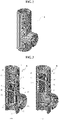
- FIG. 2 is a perspective view illustrating the branch tee for sprinkler pipes according to the first embodiment of the present invention
- FIG. 3 is a longitudinal cut-away view illustrating the branch tee in FIG. 2
- FIG. 4 is a longitudinal cross-sectional view of the branch tee in FIG. 2
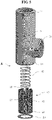
- FIG. 5 is an exploded perspective view of the branch tee in FIG. 2
- FIG. 6 is a piping diagram illustrating a sprinkler pipe system in which the branch tee in FIG.2 is installed
- FIGS. 3A , 4A , and 6A illustrate a state in which a sprinkler head is closed at normal times
- FIGS. 3B , 4B , and 6B illustrate a state in which the sprinkler head is opened when fire occurs.
- a branch tee A for sprinkler pipes includes a branch tee body 9, a first outlet 11, an inlet 10, a second outlet 12, a piston valve 13, and an inner wall groove 18.
- the branch tee body 9 has an overall shape of a cylinder, and the first outlet 11 is disposed on one end of the branch tee body 9.
- the first outlet 11 is connected to a pipe of a closed sprinkler head, and fire extinguishing water is transferred to the closed sprinkler head through the first outlet 11.
- the closed sprinkler head (refer to reference numeral 1 in FIG. 6 ) includes a heat sensing part capable of sensing hot fire heat and sprinkles fire extinguishing water by opening the head when fire occurs.
- the inlet 10 is disposed on the other end of the branch tee body 9.
- the inlet 10 is connected to the water supply pipe (refer to reference numeral 3 in FIG. 6 ) and receives the fire extinguishing water.
- the water supply pipe 3 is connected to a fire extinguishing pump or a pipe of waterworks.
- the second outlet 12 is disposed on a sidewall of the branch tee body 9.
- the first outlet 12 is connected to a pipe of a closed-type sprinkler head, and fire extinguishing water is transferred to the closed-type sprinkler head through the first outlet 12.
- the open sprinkler head (refer to reference numeral 25 in FIG. 6 ) does not include a heat sensing part and determines whether water is sprinkled by opening and closing a valve according to fire occurrence while always opening a water sprinkling hole.
- the open sprinkler head has a dry-type pipe.
- the piston valve 13 is disposed in the branch tee body 9 and simultaneously controls opening and closing of the first outlet 11 and the second outlet 12 while moving in a longitudinal direction of the branch tee body 9 due to a fluid pressure difference in the branch tee body 9 when fire occurs.
- the piston valve 13 includes a main blocking member 14a controlling opening and closing of the first outlet 11 and a sub-blocking member 14b controlling opening and closing of the second outlet 12.
- the piston valve 13 has an overall shape of a mini-cylinder so that the piston valve 13 substantially closely contacts an inner circumferential surface of the branch tee body 9.
- the main blocking member 14a includes a disk plate disposed in a transverse direction in the mini-cylinder and block the fire extinguishing water in a direction from the inlet 10 to the first outlet 11 in the branch tee. Accordingly, the main blocking member 14a determines whether the closed sprinkler head sprinkles the fire extinguishing water.
- the sub-blocking member 14b covers the inside of the branch tee adjacent to the second outlet 12 at normal times or when fire does not occur (state (A)). Accordingly, the sub-blocking member 14b determines whether the open sprinkler head sprinkles the fire extinguishing water.
- openings 17 and 19 for defining a flow path in upper and lower portions of the main blocking member 14a are defined in the sidewall of the mini-cylinder constituting the piston valve 13.
- the openings 17 and 19 operate with the inner wall groove 18 to define a flow path that is continuously defined from the inlet 10 to the first outlet 11.
- the inner wall groove 18, which is defined in the inner wall of the branch tee body 9, is disposed between the piston valve 13 and the first outlet 11.
- the inner wall groove 18 may be integrated with the inner wall along a circumference thereof or defined by a combination of a plurality of separated grooves.
- a spring 20 is disposed between the first outlet 11 and the piston valve 13 or between the first outlet 11 and the main blocking member 14a.
- the piston valve 13 moves toward the inlet 10 due to an elastic force of the spring 20, and the sub-blocking member 14b covers the second outlet 12.
- a spring stopper 21 is provided on an inner circumferential surface of the branch tee body 9 between the first outlet 11 and the inner wall groove 18 to fix an upper end of the spring 20.
- the stopper 21 is not separately provided, the substantially same effect may be achieved through a coupling relationship with an external pipe. For example, when the pipe of the closed sprinkler head is screw-coupled to a screw groove defined in the inner circumferential surface of the first outlet 11, the pipe of the closed sprinkler head plays the substantially same role as the spring stopper 21.
- a snap ring 23 is installed on the inner circumferential surface, which is adjacent to the inlet 10, of the branch tee body 9 to prevent the piston valve 13 from moving downward, thereby preventing separation of the piston valve 13.
- the snap ring 23 is not separately provided, the substantially same effect may be achieved through a coupling relationship with an external pipe.
- the water supply pipe when the water supply pipe is screw-coupled to the screw groove defined in the inner circumferential surface of the inlet 10, the water supply pipe may play the substantially same role as the snap ring 23.
- the branch tee A may be easily assembled.
- the spring 20 and the piston valve 13 may be fixed to the inside of the branch tee body 9 by the spring stopper 21 and the snap ring 23.
- the snap ring 23 may be inserted and fixed to the groove defined in the inner wall of the branch tee body 9.
- the sprinkler pipe system includes: the branch tee A; the water supply pipe connected to the inlet of the branch tee A; the closed sprinkler head 1 connected to the first outlet of the branch tee A through a pipe; and the open sprinkler head 25 connected to the second outlet of the branch tee A through a pipe.
- the pipe system according to the present invention uses the closed sprinkler head as a main head for sensing whether fire occurs and the open sprinkler head as a sub-head that operates with the main head to automatically sprinkle the fire extinguishing water.
- the overall inside of the branch tee body 9 has a constant pressure, and the piston valve 13 moves toward the inlet 10 due to the pressure of the spring 20.
- the main blocking member 14a shuts-off the inside, which heads toward the first outlet 11, of the branch tee
- the sub-blocking member 14b shuts-off the inside, which is adjacent to the second outlet 12, of the branch tee.
- the inner pressure of the first outlet 11 decreases, and, due to a fluid pressure difference in the branch tee body 9, the piston valve 13 moves toward the first outlet 11.
- the main blocking member 14a moves upwards and stops at a position overlapping the inner wall groove 18, a flow path is defined along an edge of the main blocking member 14a. Specifically, the flow path is defined in a sequence of the opening 17, the inner wall groove 18, and the opening 19.
- the sub-blocking member 14b moves toward the first outlet 11
- the second outlet 12 is opened.
- fire when the sprinkler pipe system according to the present invention is applied to the rack-type warehouse with high fire load, fire may be effectively distinguished. That is, typically, when a combustible product 27 is stacked on a rack 26 having a plurality of stories, fire may not be effectively distinguished due to the skipping effect and an obstacle to sprinkling water.
- the closed sprinkler head 1 is installed around the ceiling 6 to easily detect the ceiling jet flow caused by fire heat, and, therebelow, the open sprinkler head 25 operating together with the closed sprinkler head 1 is installed by using the branch tee A according to the present invention, fire may be suppressed regardless of the skipping effect and the obstacle to sprinkling water.
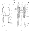
- FIG. 8 which is a modified example of FIG. 4 , is a longitudinal cross-sectional view illustrating the branch tee for sprinkler pipes according to the second embodiment. Different points from the first embodiment (refer to FIGS. 2 to 7 ) will be mainly described for convenience of description.
- a first outlet 11 which is connected to the closed sprinkler head, is disposed on a sidewall of one end of a branch tee body 9.
- the first outlet 11 may overlap an inner wall groove 18.
- the inner wall groove 18 is additionally defined in the inner circumferential surface of the branch tee body 9 in the embodiment, the embodiment is not limited thereto.
- the first outlet 11 or a passage 18' connected to the first outlet 11 may correspond to the inner wall groove 18.
- FIG. 9 is a perspective view illustrating the branch tee for sprinkler pipes according to the third embodiment
- FIG. 10 is a longitudinal cut-away view of the branch tee in FIG. 9
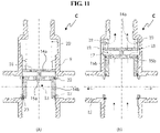
- FIG. 11 is a longitudinal cross-sectional view of the branch tee in FIG. 9
- FIG. 12 is an exploded perspective view of the branch tee in FIG. 9
- FIG. 13 is a piping diagram of a sprinkler pipe system in which the branch tee in FIG. 9 is installed. Different points from the first embodiment (refer to FIGS. 2 to 7 ) will be mainly described for convenience of description.
- a branch tee C for sprinkler pipes includes a plurality of second outlet 12 disposed on the sidewall of a branch tee body 9. Although four second outlets 12 are exemplarily described in the embodiment, the embodiment of the present invention is not limited to the number of the second outlets 12.
- a piston valve 13 has the substantially same function as the previous embodiment, the shape thereof is slightly modified. That is, openings 17 defined in a sidewall of the piston valve 13 are overall connected to each other.
- an additional disk 15a disposed parallel to a main blocking member 14a and coupled to the main blocking member 14a through a connecting member is provided below the main blocking member 14a.
- a sub-blocking member 14b is disposed below the additional disk 15a and coupled to an edge of the additional disk 15a. At least one opening 15b is defined in the additional disk 15a.
- the closed sprinkler heads 1 are arranged while being spaced a predetermined distance from each other in a place having many combustible products therein and thus having high possibility of fire occurrence, e.g., an underground parking lot and a warehouse to prevent the skipping effect.
- the branch tee C is coupled to a lower portion of the pipe of the closed sprinkler head 1.
- a dry-type pipe is connected to the branch tee C in a horizontal direction through four second outlets 12.
- a water supply pipe 3 is connected to the inlet 10 disposed on a lower portion of the branch tee C.
- the four dry-type pipes are gathered through a connecting pipe P.
- the connecting pipe P includes four inlets in a horizontal direction and an outlet in a downward direction.
- An open sprinkler head 25 is installed on the outlet of the connecting pipe P.
- the second outlet 12 of the branch tee C is also opened. Accordingly, since one closed sprinkler head 1 disposed on the ceiling and four open sprinkler head 25 disposed around the closed sprinkler head 1 sprinkle fire extinguishing water together, the skipping effect may be prevented, and the sprinkler heads may be densely arranged to enhance a water sprinkling density.
- FIG. 14 is a perspective view illustrating the branch tee for sprinkler pipes according to the present invention
- FIG. 15 is a longitudinal cut-away view of the branch tee in FIG. 14
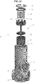
- FIG. 16 is a longitudinal cross-sectional view of the branch tee in FIG. 14
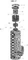
- FIG. 17 is an exploded perspective view of the branch tee in FIG. 14 .
- Different points from the first embodiment (refer to FIGS. 2 to 7 ) will be mainly described for convenience of description.
- an inlet 10 connected to a water supply pipe is formed on a sidewall of the branch tee body 9. Accordingly, when fire extinguishing water is introduced into a branch tee D in a side direction, the fire extinguishing water is sprinkled through a closed sprinkler head disposed thereabove and an open sprinkler head disposed therebelow.
- a piston valve 13 includes a main blocking member 14a covering an inside of the branch tee, which is adjacent to a first outlet 11, and a sub-blocking member 14b covering an inside of the branch tee, which is adjacent to the second outlet 12.
- the main blocking member 14a and the sub-blocking member 14b include disk plates disposed parallel to each other, and the disk plates are coupled to each other through a connecting member 30a such as a stick.
- the main blocking member 14a may have a surface area greater than that of the sub-blocking member 14b.
- the main blocking member 14a is prevented from moving further downwards by a projection 32 protruding from an inner wall of the branch tee body 9.
- the sub-blocking member 14b is inserted through a space defined by the projection 32 to cover the second outlet 12.
- a guide member 30b assisting a smooth repetition movement of the piston valve 13 may be provided on an outer circumferential surface of the connecting member 30a.
- the guide member 30b may have a shape of a plurality of blades.
- a spring stopper 31 is provided as an independent member and inserted through the first outlet 11 instead of being fixed to the branch tee body 9.
- a snap ring 23 for preventing the piston valve 13 and the spring stopper 31 from being separated are disposed above the spring stopper 31. Referring to FIG. 17 , when the piston valve 13, the spring 20, the spring stopper 31, and the snap ring 23 are sequentially inserted through the first outlet 11 of the branch tee body 9 and then assembled, the branch tee D according to the embodiment may be easily assembled.
- FIG. 18 which is a modified example of FIG. 16 , is a longitudinal cross-sectional view illustrating the branch tee for sprinkler pipes according to the fifth embodiment. Different points from the fourth embodiment (refer to FIGS. 14 to 17 ) will be mainly described for convenience of description.
- a first outlet 11 which is connected to the closed sprinkler head, is disposed on a sidewall of one end of a branch tee body 9.
- the first outlet 11 may overlap an inner wall groove 18.
- the inner wall groove is not additionally defined in an inner circumferential surface of the branch tee body 9 in the embodiment, the first outlet 11 or a passage 18' connected to the first outlet 11 may correspond to the inner wall groove 18.
- Reference numeral 34 that is not described in FIG. 18 is a branch tee cap.
- FIG. 19 is a perspective view illustrating the branch tee for sprinkler pipes according to the sixth embodiment
- FIG. 20 is a longitudinal cut-away view illustrating the branch tee in FIG. 19
- FIG. 21 is a longitudinal cross-sectional view illustrating the branch tee in FIG. 19
- FIG. 22 is an exploded perspective view illustrating the branch tee in FIG. 19 .
- Different points from the fourth embodiment (refer to FIGS. 14 to 17 ) will be mainly described for convenience of description.
- a branch tee F for sprinkler pipes includes a plurality of second outlets 12 disposed on a sidewall of a branch tee body 9. Although four second outlets 12 are exemplarily described in the embodiment, the embodiment of the present invention is not limited to the number of the second outlets 12.
- a piston valve 13 has the substantially same function as the third embodiment, the shape thereof is slightly modified. That is, a connecting member 30a extends below a sub-blocking member 14b, and an additional blocking member 40 is coupled to the connecting member 30a below the sub-blocking member 14b.
- the additional blocking member 40 has a cylindrical shape and defines a flow path 15 therein.
- the sub-blocking member 14b serves to cover between the inlet 10 and the second outlet 12
- the additional blocking member 40 serves to directly cover the second outlet 12.
- Reference numeral 33 that is not described in FIGS. 20 and 21 is a micro through-hole for water discharging.
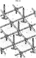
- FIG. 23 is a piping diagram illustrating a sprinkler pipe system according to embodiments of the present invention
- FIG. 24 is a view illustrating a state in which ceiling heights between the sprinkler pipe system in FIG. 23 and pipe system according to a prior art are compared.
- the ceiling height is defined as a height from a ground to ceiling facilities, i.e., the sprinkler pipe or sprinkler head.
- the downward open sprinkler head 25 is installed at the substantially same height as the obstacle to sprinkling water 7, the skipping effect does not occur, and furthermore, water sprinkling is not interfered by the obstacle to sprinkling water 7.
- FIG. 24 when the upward head 1 and the drain valve 4 are installed in consideration of possibility of freezing of a typical sprinkler pipe, a ceiling height h1 is lowest in FIG. 24A . Also, when a typical dry pendent head is used in piping ( FIG. 24B ), although the downward head 5 may be used without possibility of freezing, the baffle plate 5 is used to prevent the skipping effect, and thus, a ceiling height h2 is second lowest. However, since the pipe system according to the present invention ( FIG. 24C ) uses the open sprinkler head 25, the pipe system may not be affected by the skipping effect, and the baffle plate may be unnecessary, to secure a highest ceiling height h3. Furthermore, since the sprinkler head does not protrude from the obstacle to sprinkling water 7, an aesthetic appearance may be provided.
Landscapes
- Engineering & Computer Science (AREA)
- General Engineering & Computer Science (AREA)
- Mechanical Engineering (AREA)
- Health & Medical Sciences (AREA)
- Public Health (AREA)
- Business, Economics & Management (AREA)
- Emergency Management (AREA)
- Fire-Extinguishing By Fire Departments, And Fire-Extinguishing Equipment And Control Thereof (AREA)
- Branch Pipes, Bends, And The Like (AREA)
- Pipe Accessories (AREA)
- Fluid-Driven Valves (AREA)
- Safety Valves (AREA)
Claims (3)
- Manchon de dérivation pour tubes de sprinkler, qui commande l'écoulement d'eau automatiquement, comprenant :un corps de manchon de dérivation (9) ayant une forme cylindrique,une première sortie (11) formée sur une extrémité dudit corps de manchon de dérivation (9) et configurée pour raccordement à un tube d'une tête de sprinkler fermée,une entrée (10) formée sur une paroi latérale dudit corps de manchon de dérivation (9) et configurée pour raccordement à un tube d'alimentation d'eau,une deuxième sortie (12) formée sur l'autre extrémité du corps de manchon de dérivation (9) et configurée pour raccordement à un tube d'une tête de sprinkler ouverte,une vanne à piston en forme de minicylindre située dans le corps de manchon de dérivation (9) et configurée pour commander simultanément l'ouverture et la fermeture de la première sortie (11) et la deuxième sortie (12), pendant qu'elle se déplace dans une direction longitudinale du corps de manchon de dérivation (9) entre une première position et une deuxième position dans le corps de manchon de dérivation (9) en cas d'incendie, etune rainure de paroi intérieure (18) formée sur une paroi intérieure du corps de manchon de dérivation (9) entre la vanne à piston (13) et la première sortie (11),ladite vanne à piston comprenant : un élément de blocage principal (14a) adjacent à la première sortie (11) et configuré pour commander l'ouverture et la fermeture de la première sortie (11) quand il n'y a pas d'incendie, et un sous-élément de blocage (14b) raccordé à l'élément de blocage principal adjacent à la deuxième sortie (12) et configuré pour commander l'ouverture et la fermeture de la deuxième sortie (12) quand il n'y a pas d'incendie, ledit élément de blocage principal (14a) et ledit sous-élément de blocage (14b) étant en forme de disques arrangés parallèles l'un à l'autre et raccordés par un élément de raccordement (30a),une saillie (32) saillant de la paroi intérieure du corps de manchon de dérivation (9), située au-dessus de l'entrée (10) et configurée pour prévenir le blocage de l'entrée (10) par ledit élément de blocage principal (14a),dans lequel la rainure de paroi intérieure (18) est située entre la saillie (32) et la première sortie (11) et espacée de la saillie (32),dans lequel ledit minicylindre est composé du disque de l'élément de blocage principal (14a) et une paroi latérale en contact avec une surface enveloppe intérieure du corps de manchon de dérivation (9), et saillant du côté du disque en face de la première sortie (11), etdans lequel des apertures (17, 19) sont définies dans la paroi latérale du minicylindre constituant la vanne à piston (13),un ressort (20) situé entre la première sortie (11) et l'élément de blocage principal (14a),un bouchon de ressort (31) situé sur une surface enveloppe intérieure du corps de manchon de dérivation (9) entre la première sortie (11) et la rainure de paroi intérieure (18) configuré pour fixer une extrémité supérieure dudit ressort (20), etune bague de retenue (23) située au-dessus du bouchon de ressort (31) configurée pour prévenir la séparation de la vanne de piston (13) du bouchon de ressort (31).
- Manchon de dérivation selon la revendication 1, dans lequel, quand le sprinkler fermé s'ouvre en case d'incendie, la vanne de piston se déplace vers la première sortie (11) en raison de la différence de pression du fluide dans le corps de manchon de dérivation (9), l'élément de blocage principal (14a) se chevauche à la rainure de paroi intérieure (18) pour définir un trajet de courant le long d'un bord de l'élément de blocage principal (14a), et le sous-élément de blocage (14b) ouvre la deuxième sortie (12).
- Système de tubes de sprinkler, comprenant :un manchon de dérivation selon la revendication 1,un tube d'alimentation d'eau raccordé à l'entrée (10) du manchon de dérivation,une tête de sprinkler fermée, raccordée à la première sortie (11) du manchon de dérivation au moyen d'un tube, etune tête de sprinkler ouverte, raccordée à la deuxième sortie (12) du manchon de dérivation au moyen d'un tube.
Applications Claiming Priority (3)
| Application Number | Priority Date | Filing Date | Title |
|---|---|---|---|
| KR20150120877 | 2015-08-27 | ||
| KR1020160105678A KR20170026154A (ko) | 2015-08-27 | 2016-08-19 | 스프링클러 배관의 유수제어기능이 있는 분기용 티 및 그것을 이용한 스키핑 현상의 영향을 받지 않는 스프링클러 배관 시공 방법 |
| PCT/KR2016/009562 WO2017034382A1 (fr) | 2015-08-27 | 2016-08-29 | Jonction droite simple pour tuyau d'extincteur automatique pour commander automatiquement l'écoulement de l'eau, et système de tuyau d'extincteur le comprenant |
Publications (3)
| Publication Number | Publication Date |
|---|---|
| EP3342467A1 EP3342467A1 (fr) | 2018-07-04 |
| EP3342467A4 EP3342467A4 (fr) | 2019-04-03 |
| EP3342467B1 true EP3342467B1 (fr) | 2022-11-02 |
Family
ID=58404724
Family Applications (1)
| Application Number | Title | Priority Date | Filing Date |
|---|---|---|---|
| EP16839670.3A Active EP3342467B1 (fr) | 2015-08-27 | 2016-08-29 | Jonction droite simple pour tuyau d'extincteur automatique pour commander automatiquement l'écoulement de l'eau, et système de tuyau d'extincteur le comprenant |
Country Status (5)
| Country | Link |
|---|---|
| US (1) | US10843019B2 (fr) |
| EP (1) | EP3342467B1 (fr) |
| JP (1) | JP6778751B2 (fr) |
| KR (2) | KR20170026154A (fr) |
| CN (1) | CN108290062B (fr) |
Families Citing this family (16)
| Publication number | Priority date | Publication date | Assignee | Title |
|---|---|---|---|---|
| US10575633B2 (en) * | 2015-12-22 | 2020-03-03 | LDR Global Industries, LLC | Pipe rack system |
| US10722741B2 (en) * | 2017-12-01 | 2020-07-28 | International Business Machines Corporation | Automatically generating fire-fighting foams to combat Li-ion battery failures |
| US10912963B2 (en) * | 2017-12-01 | 2021-02-09 | International Business Machines Corporation | Automatically generating fire-fighting foams to combat Li-ion battery failures |
| US11241599B2 (en) * | 2018-05-09 | 2022-02-08 | William A. Enk | Fire suppression system |
| CA3162713A1 (fr) * | 2019-11-25 | 2021-06-03 | Sprinkler Stop, Llc | Soupape en ligne pour remplacement de tete d'arroseur |
| US12017103B2 (en) | 2020-06-05 | 2024-06-25 | Tyco Fire Products Lp | Adapter for concealed sprinkler |
| KR102603787B1 (ko) | 2020-09-25 | 2023-11-17 | 주식회사 지엠엔지니어링 | 스프링클러 배관용 분기티 |
| CN112431987A (zh) * | 2020-12-29 | 2021-03-02 | 安徽铜都流体科技股份有限公司 | 伸缩式三通换向打球装置及应用 |
| JP7772614B2 (ja) * | 2021-03-22 | 2025-11-18 | 日本ドライケミカル株式会社 | 防災設備、この防災設備を備えた燃料電池車両、水素トレーラ及び定置式設備 |
| KR102605813B1 (ko) * | 2021-05-26 | 2023-11-29 | 엄태평 | 유체 흐름에 따라 개방되는 분기용 티 밸브 및 이를 포함하는 분기용 티 밸브 시스템 |
| US20250043897A1 (en) * | 2021-09-08 | 2025-02-06 | Kim Jin Tai | Branch tee for sprinkler pipes controlling water stream automatically and sprinkler piping system having the same |
| CN118076417A (zh) * | 2021-09-08 | 2024-05-24 | 金镇泰 | 用于自动控制水流的喷水管道的分支三通和具有该分支三通的喷水管道系统 |
| JP2023049179A (ja) * | 2021-09-29 | 2023-04-10 | 積水化学工業株式会社 | 多口継手及び配管システム |
| JP7783767B2 (ja) | 2022-03-24 | 2025-12-10 | 日本ドライケミカル株式会社 | ハウジング形継手の冷却システム |
| USD1078158S1 (en) * | 2022-05-26 | 2025-06-03 | Sean Wayne Wigand | Makeup implement |
| US20260098583A1 (en) * | 2024-08-14 | 2026-04-09 | The Boeing Company | Pneumatic valves, pneumatic apparatuses, and methods for controlling pneumatic flow |
Citations (2)
| Publication number | Priority date | Publication date | Assignee | Title |
|---|---|---|---|---|
| US6357467B1 (en) * | 2000-03-27 | 2002-03-19 | Grinnell Corporation | Automatic water supply shutoff valve |
| US20050081928A1 (en) * | 2003-10-17 | 2005-04-21 | Burke David H. | Flow control valve |
Family Cites Families (14)
| Publication number | Priority date | Publication date | Assignee | Title |
|---|---|---|---|---|
| US4013088A (en) * | 1975-05-19 | 1977-03-22 | Braukmann Armaturen Ag | Valve structure |
| US4243064A (en) * | 1977-06-03 | 1981-01-06 | Tuxhorn Kg | Bypass valve for pumps, heating systems and the like |
| JP2594320Y2 (ja) | 1992-12-22 | 1999-04-26 | 千住スプリンクラー株式会社 | 一斉開放弁 |
| CA2116587A1 (fr) * | 1994-02-28 | 1995-08-29 | Alexandre Karroum | Vanne de commande d'extinction automatique pour secteur froid |
| JP2000279550A (ja) * | 1999-03-31 | 2000-10-10 | Nittan Co Ltd | 消火及び火災抑制用閉鎖型噴霧放水ヘッド及びこれの建造物への設置方法 |
| JP4495832B2 (ja) * | 2000-05-31 | 2010-07-07 | ヤマトプロテック株式会社 | 差圧式開放弁および開放式スプリンクラー設備 |
| KR100498639B1 (ko) | 2002-08-13 | 2005-07-01 | (주)스타코넷 | 스프링클러 설비용 건식밸브 |
| JP2005000508A (ja) | 2003-06-13 | 2005-01-06 | Yamato Protec Co | 減圧開放型一斉開放弁を用いる消火設備 |
| JP4334556B2 (ja) * | 2006-07-31 | 2009-09-30 | 能美防災株式会社 | スプリンクラヘッド取付具 |
| KR101200621B1 (ko) | 2010-04-14 | 2012-11-12 | 서울메트로 | 동파방지용 스프링클러 |
| JP4999211B2 (ja) * | 2010-06-03 | 2012-08-15 | ホーチキ株式会社 | 放水継手 |
| KR101498930B1 (ko) * | 2013-12-20 | 2015-03-04 | 한국에너지기술연구원 | 난방, 급탕용 가정세대유닛 시스템 |
| CN203809796U (zh) * | 2014-05-14 | 2014-09-03 | 福建省三鲸消防器材有限公司 | 一种干式报警阀 |
| CN104288948B (zh) * | 2014-09-22 | 2017-06-06 | 铁道第三勘察设计院集团有限公司 | 多功能自动喷水灭火装置 |
-
2016
- 2016-08-19 KR KR1020160105678A patent/KR20170026154A/ko not_active Withdrawn
- 2016-08-29 JP JP2018530453A patent/JP6778751B2/ja active Active
- 2016-08-29 CN CN201680062866.2A patent/CN108290062B/zh not_active Expired - Fee Related
- 2016-08-29 KR KR1020167034141A patent/KR101782899B1/ko not_active Expired - Fee Related
- 2016-08-29 EP EP16839670.3A patent/EP3342467B1/fr active Active
- 2016-08-29 US US15/756,013 patent/US10843019B2/en not_active Expired - Fee Related
Patent Citations (2)
| Publication number | Priority date | Publication date | Assignee | Title |
|---|---|---|---|---|
| US6357467B1 (en) * | 2000-03-27 | 2002-03-19 | Grinnell Corporation | Automatic water supply shutoff valve |
| US20050081928A1 (en) * | 2003-10-17 | 2005-04-21 | Burke David H. | Flow control valve |
Also Published As
| Publication number | Publication date |
|---|---|
| JP6778751B2 (ja) | 2020-11-04 |
| CN108290062B (zh) | 2021-06-01 |
| EP3342467A4 (fr) | 2019-04-03 |
| US20180243596A1 (en) | 2018-08-30 |
| KR20170035837A (ko) | 2017-03-31 |
| JP2018534088A (ja) | 2018-11-22 |
| KR101782899B1 (ko) | 2017-09-28 |
| EP3342467A1 (fr) | 2018-07-04 |
| KR20170026154A (ko) | 2017-03-08 |
| CN108290062A (zh) | 2018-07-17 |
| US10843019B2 (en) | 2020-11-24 |
Similar Documents
| Publication | Publication Date | Title |
|---|---|---|
| EP3342467B1 (fr) | Jonction droite simple pour tuyau d'extincteur automatique pour commander automatiquement l'écoulement de l'eau, et système de tuyau d'extincteur le comprenant | |
| CA2123707C (fr) | Installation de lutte contre les incendies | |
| KR101662590B1 (ko) | 스프링클러 방식의 건물용 소방장치 | |
| TW201711723A (zh) | 整合之流體控制閥及閥致動器總成 | |
| EP3206759A1 (fr) | Système d'extinction d'incendie | |
| KR102158705B1 (ko) | 나선형 유로가 형성된 디플렉터가 구비된 스프링클러 헤드 | |
| KR102069294B1 (ko) | 건축물의 화재 확산 방지 외벽구조 | |
| KR101267346B1 (ko) | 유체 분사 노즐 및 이를 포함하는 스프링클러 시스템 | |
| JP7735550B2 (ja) | 自動で流水を制御するスプリンクラー配管用ブランチティー及びこれを含むスプリンクラー配管システム | |
| KR20180102392A (ko) | 노즐개폐부를 포함하는 가스계 소화설비 노즐 및 이를 포함하는 소방설비 | |
| KR102721997B1 (ko) | 과압방지기능이 구비된 일체형 복합밸브 | |
| JP3806221B2 (ja) | 消火設備及びその散水ヘッド | |
| KR20120021588A (ko) | 스프링클러 헤드 | |
| KR101040075B1 (ko) | 조기반응형 스프링클러 헤드 | |
| KR200443942Y1 (ko) | 자동식소화기의 방출구 | |
| JP5734227B2 (ja) | スプリンクラヘッド取付具 | |
| KR200431866Y1 (ko) | 스프링클러 헤드 마감링 | |
| US12599794B2 (en) | Upright sprinkler and a sprinkler system | |
| WO2017034382A1 (fr) | Jonction droite simple pour tuyau d'extincteur automatique pour commander automatiquement l'écoulement de l'eau, et système de tuyau d'extincteur le comprenant | |
| CN118076417A (zh) | 用于自动控制水流的喷水管道的分支三通和具有该分支三通的喷水管道系统 | |
| KR102630703B1 (ko) | 수벽 노즐장치 | |
| KR101618864B1 (ko) | 차압조절기능을 갖는 소방용 감압밸브 | |
| KR101291182B1 (ko) | 스프링클러 알람 밸브 및 이를 이용한 소방 시스템 | |
| KR20100082160A (ko) | 스프링클러 헤드 |
Legal Events
| Date | Code | Title | Description |
|---|---|---|---|
| STAA | Information on the status of an ep patent application or granted ep patent |
Free format text: STATUS: THE INTERNATIONAL PUBLICATION HAS BEEN MADE |
|
| PUAI | Public reference made under article 153(3) epc to a published international application that has entered the european phase |
Free format text: ORIGINAL CODE: 0009012 |
|
| STAA | Information on the status of an ep patent application or granted ep patent |
Free format text: STATUS: REQUEST FOR EXAMINATION WAS MADE |
|
| 17P | Request for examination filed |
Effective date: 20180326 |
|
| AK | Designated contracting states |
Kind code of ref document: A1 Designated state(s): AL AT BE BG CH CY CZ DE DK EE ES FI FR GB GR HR HU IE IS IT LI LT LU LV MC MK MT NL NO PL PT RO RS SE SI SK SM TR |
|
| AX | Request for extension of the european patent |
Extension state: BA ME |
|
| DAV | Request for validation of the european patent (deleted) | ||
| DAX | Request for extension of the european patent (deleted) | ||
| RIC1 | Information provided on ipc code assigned before grant |
Ipc: F16K 17/04 20060101ALI20190221BHEP Ipc: A62C 35/68 20060101ALI20190221BHEP Ipc: F16K 11/07 20060101ALI20190221BHEP Ipc: A62C 35/58 20060101ALI20190221BHEP Ipc: F16K 15/02 20060101ALI20190221BHEP Ipc: F16L 41/02 20060101ALI20190221BHEP Ipc: F16L 41/03 20060101ALI20190221BHEP Ipc: F16K 11/02 20060101ALI20190221BHEP Ipc: A62C 37/08 20060101AFI20190221BHEP |
|
| A4 | Supplementary search report drawn up and despatched |
Effective date: 20190228 |
|
| STAA | Information on the status of an ep patent application or granted ep patent |
Free format text: STATUS: EXAMINATION IS IN PROGRESS |
|
| 17Q | First examination report despatched |
Effective date: 20200406 |
|
| GRAP | Despatch of communication of intention to grant a patent |
Free format text: ORIGINAL CODE: EPIDOSNIGR1 |
|
| STAA | Information on the status of an ep patent application or granted ep patent |
Free format text: STATUS: GRANT OF PATENT IS INTENDED |
|
| INTG | Intention to grant announced |
Effective date: 20220519 |
|
| GRAS | Grant fee paid |
Free format text: ORIGINAL CODE: EPIDOSNIGR3 |
|
| GRAA | (expected) grant |
Free format text: ORIGINAL CODE: 0009210 |
|
| STAA | Information on the status of an ep patent application or granted ep patent |
Free format text: STATUS: THE PATENT HAS BEEN GRANTED |
|
| AK | Designated contracting states |
Kind code of ref document: B1 Designated state(s): AL AT BE BG CH CY CZ DE DK EE ES FI FR GB GR HR HU IE IS IT LI LT LU LV MC MK MT NL NO PL PT RO RS SE SI SK SM TR |
|
| REG | Reference to a national code |
Ref country code: GB Ref legal event code: FG4D |
|
| REG | Reference to a national code |
Ref country code: CH Ref legal event code: EP Ref country code: AT Ref legal event code: REF Ref document number: 1528321 Country of ref document: AT Kind code of ref document: T Effective date: 20221115 |
|
| REG | Reference to a national code |
Ref country code: DE Ref legal event code: R096 Ref document number: 602016076109 Country of ref document: DE |
|
| REG | Reference to a national code |
Ref country code: IE Ref legal event code: FG4D |
|
| REG | Reference to a national code |
Ref country code: LT Ref legal event code: MG9D |
|
| REG | Reference to a national code |
Ref country code: NL Ref legal event code: MP Effective date: 20221102 |
|
| REG | Reference to a national code |
Ref country code: AT Ref legal event code: MK05 Ref document number: 1528321 Country of ref document: AT Kind code of ref document: T Effective date: 20221102 |
|
| PG25 | Lapsed in a contracting state [announced via postgrant information from national office to epo] |
Ref country code: SE Free format text: LAPSE BECAUSE OF FAILURE TO SUBMIT A TRANSLATION OF THE DESCRIPTION OR TO PAY THE FEE WITHIN THE PRESCRIBED TIME-LIMIT Effective date: 20221102 Ref country code: PT Free format text: LAPSE BECAUSE OF FAILURE TO SUBMIT A TRANSLATION OF THE DESCRIPTION OR TO PAY THE FEE WITHIN THE PRESCRIBED TIME-LIMIT Effective date: 20230302 Ref country code: NO Free format text: LAPSE BECAUSE OF FAILURE TO SUBMIT A TRANSLATION OF THE DESCRIPTION OR TO PAY THE FEE WITHIN THE PRESCRIBED TIME-LIMIT Effective date: 20230202 Ref country code: LT Free format text: LAPSE BECAUSE OF FAILURE TO SUBMIT A TRANSLATION OF THE DESCRIPTION OR TO PAY THE FEE WITHIN THE PRESCRIBED TIME-LIMIT Effective date: 20221102 Ref country code: FI Free format text: LAPSE BECAUSE OF FAILURE TO SUBMIT A TRANSLATION OF THE DESCRIPTION OR TO PAY THE FEE WITHIN THE PRESCRIBED TIME-LIMIT Effective date: 20221102 Ref country code: ES Free format text: LAPSE BECAUSE OF FAILURE TO SUBMIT A TRANSLATION OF THE DESCRIPTION OR TO PAY THE FEE WITHIN THE PRESCRIBED TIME-LIMIT Effective date: 20221102 Ref country code: AT Free format text: LAPSE BECAUSE OF FAILURE TO SUBMIT A TRANSLATION OF THE DESCRIPTION OR TO PAY THE FEE WITHIN THE PRESCRIBED TIME-LIMIT Effective date: 20221102 |
|
| PG25 | Lapsed in a contracting state [announced via postgrant information from national office to epo] |
Ref country code: RS Free format text: LAPSE BECAUSE OF FAILURE TO SUBMIT A TRANSLATION OF THE DESCRIPTION OR TO PAY THE FEE WITHIN THE PRESCRIBED TIME-LIMIT Effective date: 20221102 Ref country code: PL Free format text: LAPSE BECAUSE OF FAILURE TO SUBMIT A TRANSLATION OF THE DESCRIPTION OR TO PAY THE FEE WITHIN THE PRESCRIBED TIME-LIMIT Effective date: 20221102 Ref country code: LV Free format text: LAPSE BECAUSE OF FAILURE TO SUBMIT A TRANSLATION OF THE DESCRIPTION OR TO PAY THE FEE WITHIN THE PRESCRIBED TIME-LIMIT Effective date: 20221102 Ref country code: IS Free format text: LAPSE BECAUSE OF FAILURE TO SUBMIT A TRANSLATION OF THE DESCRIPTION OR TO PAY THE FEE WITHIN THE PRESCRIBED TIME-LIMIT Effective date: 20230302 Ref country code: HR Free format text: LAPSE BECAUSE OF FAILURE TO SUBMIT A TRANSLATION OF THE DESCRIPTION OR TO PAY THE FEE WITHIN THE PRESCRIBED TIME-LIMIT Effective date: 20221102 Ref country code: GR Free format text: LAPSE BECAUSE OF FAILURE TO SUBMIT A TRANSLATION OF THE DESCRIPTION OR TO PAY THE FEE WITHIN THE PRESCRIBED TIME-LIMIT Effective date: 20230203 |
|
| PG25 | Lapsed in a contracting state [announced via postgrant information from national office to epo] |
Ref country code: NL Free format text: LAPSE BECAUSE OF FAILURE TO SUBMIT A TRANSLATION OF THE DESCRIPTION OR TO PAY THE FEE WITHIN THE PRESCRIBED TIME-LIMIT Effective date: 20221102 |
|
| PG25 | Lapsed in a contracting state [announced via postgrant information from national office to epo] |
Ref country code: SM Free format text: LAPSE BECAUSE OF FAILURE TO SUBMIT A TRANSLATION OF THE DESCRIPTION OR TO PAY THE FEE WITHIN THE PRESCRIBED TIME-LIMIT Effective date: 20221102 Ref country code: RO Free format text: LAPSE BECAUSE OF FAILURE TO SUBMIT A TRANSLATION OF THE DESCRIPTION OR TO PAY THE FEE WITHIN THE PRESCRIBED TIME-LIMIT Effective date: 20221102 Ref country code: EE Free format text: LAPSE BECAUSE OF FAILURE TO SUBMIT A TRANSLATION OF THE DESCRIPTION OR TO PAY THE FEE WITHIN THE PRESCRIBED TIME-LIMIT Effective date: 20221102 Ref country code: DK Free format text: LAPSE BECAUSE OF FAILURE TO SUBMIT A TRANSLATION OF THE DESCRIPTION OR TO PAY THE FEE WITHIN THE PRESCRIBED TIME-LIMIT Effective date: 20221102 Ref country code: CZ Free format text: LAPSE BECAUSE OF FAILURE TO SUBMIT A TRANSLATION OF THE DESCRIPTION OR TO PAY THE FEE WITHIN THE PRESCRIBED TIME-LIMIT Effective date: 20221102 |
|
| REG | Reference to a national code |
Ref country code: DE Ref legal event code: R097 Ref document number: 602016076109 Country of ref document: DE |
|
| PG25 | Lapsed in a contracting state [announced via postgrant information from national office to epo] |
Ref country code: SK Free format text: LAPSE BECAUSE OF FAILURE TO SUBMIT A TRANSLATION OF THE DESCRIPTION OR TO PAY THE FEE WITHIN THE PRESCRIBED TIME-LIMIT Effective date: 20221102 Ref country code: AL Free format text: LAPSE BECAUSE OF FAILURE TO SUBMIT A TRANSLATION OF THE DESCRIPTION OR TO PAY THE FEE WITHIN THE PRESCRIBED TIME-LIMIT Effective date: 20221102 |
|
| PLBE | No opposition filed within time limit |
Free format text: ORIGINAL CODE: 0009261 |
|
| STAA | Information on the status of an ep patent application or granted ep patent |
Free format text: STATUS: NO OPPOSITION FILED WITHIN TIME LIMIT |
|
| 26N | No opposition filed |
Effective date: 20230803 |
|
| PG25 | Lapsed in a contracting state [announced via postgrant information from national office to epo] |
Ref country code: SI Free format text: LAPSE BECAUSE OF FAILURE TO SUBMIT A TRANSLATION OF THE DESCRIPTION OR TO PAY THE FEE WITHIN THE PRESCRIBED TIME-LIMIT Effective date: 20221102 |
|
| REG | Reference to a national code |
Ref country code: DE Ref legal event code: R119 Ref document number: 602016076109 Country of ref document: DE |
|
| PG25 | Lapsed in a contracting state [announced via postgrant information from national office to epo] |
Ref country code: MC Free format text: LAPSE BECAUSE OF FAILURE TO SUBMIT A TRANSLATION OF THE DESCRIPTION OR TO PAY THE FEE WITHIN THE PRESCRIBED TIME-LIMIT Effective date: 20221102 |
|
| REG | Reference to a national code |
Ref country code: CH Ref legal event code: PL |
|
| PG25 | Lapsed in a contracting state [announced via postgrant information from national office to epo] |
Ref country code: MC Free format text: LAPSE BECAUSE OF FAILURE TO SUBMIT A TRANSLATION OF THE DESCRIPTION OR TO PAY THE FEE WITHIN THE PRESCRIBED TIME-LIMIT Effective date: 20221102 |
|
| PG25 | Lapsed in a contracting state [announced via postgrant information from national office to epo] |
Ref country code: LU Free format text: LAPSE BECAUSE OF NON-PAYMENT OF DUE FEES Effective date: 20230829 |
|
| GBPC | Gb: european patent ceased through non-payment of renewal fee |
Effective date: 20230829 |
|
| PG25 | Lapsed in a contracting state [announced via postgrant information from national office to epo] |
Ref country code: LU Free format text: LAPSE BECAUSE OF NON-PAYMENT OF DUE FEES Effective date: 20230829 Ref country code: CH Free format text: LAPSE BECAUSE OF NON-PAYMENT OF DUE FEES Effective date: 20230831 |
|
| REG | Reference to a national code |
Ref country code: BE Ref legal event code: MM Effective date: 20230831 |
|
| REG | Reference to a national code |
Ref country code: IE Ref legal event code: MM4A |
|
| PG25 | Lapsed in a contracting state [announced via postgrant information from national office to epo] |
Ref country code: IT Free format text: LAPSE BECAUSE OF FAILURE TO SUBMIT A TRANSLATION OF THE DESCRIPTION OR TO PAY THE FEE WITHIN THE PRESCRIBED TIME-LIMIT Effective date: 20221102 |
|
| PG25 | Lapsed in a contracting state [announced via postgrant information from national office to epo] |
Ref country code: IE Free format text: LAPSE BECAUSE OF NON-PAYMENT OF DUE FEES Effective date: 20230829 |
|
| PG25 | Lapsed in a contracting state [announced via postgrant information from national office to epo] |
Ref country code: GB Free format text: LAPSE BECAUSE OF NON-PAYMENT OF DUE FEES Effective date: 20230829 |
|
| PG25 | Lapsed in a contracting state [announced via postgrant information from national office to epo] |
Ref country code: IE Free format text: LAPSE BECAUSE OF NON-PAYMENT OF DUE FEES Effective date: 20230829 Ref country code: GB Free format text: LAPSE BECAUSE OF NON-PAYMENT OF DUE FEES Effective date: 20230829 Ref country code: FR Free format text: LAPSE BECAUSE OF NON-PAYMENT OF DUE FEES Effective date: 20230831 Ref country code: DE Free format text: LAPSE BECAUSE OF NON-PAYMENT OF DUE FEES Effective date: 20240301 |
|
| PG25 | Lapsed in a contracting state [announced via postgrant information from national office to epo] |
Ref country code: BE Free format text: LAPSE BECAUSE OF NON-PAYMENT OF DUE FEES Effective date: 20230831 |
|
| PG25 | Lapsed in a contracting state [announced via postgrant information from national office to epo] |
Ref country code: BG Free format text: LAPSE BECAUSE OF FAILURE TO SUBMIT A TRANSLATION OF THE DESCRIPTION OR TO PAY THE FEE WITHIN THE PRESCRIBED TIME-LIMIT Effective date: 20221102 |
|
| PG25 | Lapsed in a contracting state [announced via postgrant information from national office to epo] |
Ref country code: BG Free format text: LAPSE BECAUSE OF FAILURE TO SUBMIT A TRANSLATION OF THE DESCRIPTION OR TO PAY THE FEE WITHIN THE PRESCRIBED TIME-LIMIT Effective date: 20221102 |
|
| PG25 | Lapsed in a contracting state [announced via postgrant information from national office to epo] |
Ref country code: CY Free format text: LAPSE BECAUSE OF FAILURE TO SUBMIT A TRANSLATION OF THE DESCRIPTION OR TO PAY THE FEE WITHIN THE PRESCRIBED TIME-LIMIT; INVALID AB INITIO Effective date: 20160829 |
|
| PG25 | Lapsed in a contracting state [announced via postgrant information from national office to epo] |
Ref country code: HU Free format text: LAPSE BECAUSE OF FAILURE TO SUBMIT A TRANSLATION OF THE DESCRIPTION OR TO PAY THE FEE WITHIN THE PRESCRIBED TIME-LIMIT; INVALID AB INITIO Effective date: 20160829 |
|
| PG25 | Lapsed in a contracting state [announced via postgrant information from national office to epo] |
Ref country code: TR Free format text: LAPSE BECAUSE OF FAILURE TO SUBMIT A TRANSLATION OF THE DESCRIPTION OR TO PAY THE FEE WITHIN THE PRESCRIBED TIME-LIMIT Effective date: 20221102 |