EP3342490A1 - Kompakte reinigungsvorrichtung und verfahren zum betreiben der reinigungsvorrichtung - Google Patents
Kompakte reinigungsvorrichtung und verfahren zum betreiben der reinigungsvorrichtung Download PDFInfo
- Publication number
- EP3342490A1 EP3342490A1 EP17200606.6A EP17200606A EP3342490A1 EP 3342490 A1 EP3342490 A1 EP 3342490A1 EP 17200606 A EP17200606 A EP 17200606A EP 3342490 A1 EP3342490 A1 EP 3342490A1
- Authority
- EP
- European Patent Office
- Prior art keywords
- injector
- valve
- cleaning
- mixing unit
- cleaning agent
- Prior art date
- Legal status (The legal status is an assumption and is not a legal conclusion. Google has not performed a legal analysis and makes no representation as to the accuracy of the status listed.)
- Withdrawn
Links
- 238000004140 cleaning Methods 0.000 title claims abstract description 185
- 238000000034 method Methods 0.000 title claims description 14
- 239000012459 cleaning agent Substances 0.000 claims abstract description 194
- 239000007788 liquid Substances 0.000 claims abstract description 129
- XLYOFNOQVPJJNP-UHFFFAOYSA-N water Substances O XLYOFNOQVPJJNP-UHFFFAOYSA-N 0.000 claims description 141
- 238000005507 spraying Methods 0.000 claims description 50
- 239000012530 fluid Substances 0.000 claims description 37
- 239000006260 foam Substances 0.000 claims description 22
- 239000000203 mixture Substances 0.000 claims description 22
- 230000001276 controlling effect Effects 0.000 claims description 9
- 230000003247 decreasing effect Effects 0.000 claims description 6
- 230000001105 regulatory effect Effects 0.000 claims description 6
- 239000000463 material Substances 0.000 claims description 5
- 239000007787 solid Substances 0.000 claims description 4
- 238000005187 foaming Methods 0.000 abstract description 7
- 230000013011 mating Effects 0.000 abstract description 3
- 239000007789 gas Substances 0.000 description 87
- 238000009826 distribution Methods 0.000 description 12
- 235000013305 food Nutrition 0.000 description 11
- 238000012545 processing Methods 0.000 description 10
- MHAJPDPJQMAIIY-UHFFFAOYSA-N Hydrogen peroxide Chemical compound OO MHAJPDPJQMAIIY-UHFFFAOYSA-N 0.000 description 8
- 238000004891 communication Methods 0.000 description 6
- 238000003466 welding Methods 0.000 description 4
- 150000001875 compounds Chemical class 0.000 description 3
- 238000011010 flushing procedure Methods 0.000 description 3
- 229960002163 hydrogen peroxide Drugs 0.000 description 3
- 230000007246 mechanism Effects 0.000 description 3
- 230000008569 process Effects 0.000 description 3
- 230000008901 benefit Effects 0.000 description 2
- 238000010276 construction Methods 0.000 description 2
- 230000000694 effects Effects 0.000 description 2
- 239000004519 grease Substances 0.000 description 2
- 208000015181 infectious disease Diseases 0.000 description 2
- 238000002347 injection Methods 0.000 description 2
- 239000007924 injection Substances 0.000 description 2
- 238000012423 maintenance Methods 0.000 description 2
- 238000012856 packing Methods 0.000 description 2
- 230000035939 shock Effects 0.000 description 2
- 238000004659 sterilization and disinfection Methods 0.000 description 2
- 239000000126 substance Substances 0.000 description 2
- 238000011144 upstream manufacturing Methods 0.000 description 2
- 241000251468 Actinopterygii Species 0.000 description 1
- ZAMOUSCENKQFHK-UHFFFAOYSA-N Chlorine atom Chemical compound [Cl] ZAMOUSCENKQFHK-UHFFFAOYSA-N 0.000 description 1
- 229920002472 Starch Polymers 0.000 description 1
- 239000003570 air Substances 0.000 description 1
- 230000008859 change Effects 0.000 description 1
- 239000013043 chemical agent Substances 0.000 description 1
- 239000003795 chemical substances by application Substances 0.000 description 1
- 239000000460 chlorine Substances 0.000 description 1
- 229910052801 chlorine Inorganic materials 0.000 description 1
- 238000013461 design Methods 0.000 description 1
- 238000010586 diagram Methods 0.000 description 1
- 238000005553 drilling Methods 0.000 description 1
- 238000002474 experimental method Methods 0.000 description 1
- 239000004088 foaming agent Substances 0.000 description 1
- 239000010437 gem Substances 0.000 description 1
- 230000036541 health Effects 0.000 description 1
- 231100000206 health hazard Toxicity 0.000 description 1
- 230000002458 infectious effect Effects 0.000 description 1
- 238000003780 insertion Methods 0.000 description 1
- 230000037431 insertion Effects 0.000 description 1
- 230000007257 malfunction Effects 0.000 description 1
- 238000004519 manufacturing process Methods 0.000 description 1
- 235000013372 meat Nutrition 0.000 description 1
- 229910001092 metal group alloy Inorganic materials 0.000 description 1
- 238000000465 moulding Methods 0.000 description 1
- 239000004033 plastic Substances 0.000 description 1
- 230000002035 prolonged effect Effects 0.000 description 1
- 102000004169 proteins and genes Human genes 0.000 description 1
- 108090000623 proteins and genes Proteins 0.000 description 1
- -1 pump Substances 0.000 description 1
- 230000009467 reduction Effects 0.000 description 1
- 230000008439 repair process Effects 0.000 description 1
- 239000008237 rinsing water Substances 0.000 description 1
- 239000000243 solution Substances 0.000 description 1
- 239000010935 stainless steel Substances 0.000 description 1
- 229910001220 stainless steel Inorganic materials 0.000 description 1
- 235000019698 starch Nutrition 0.000 description 1
- 239000008107 starch Substances 0.000 description 1
- 239000008399 tap water Substances 0.000 description 1
- 235000020679 tap water Nutrition 0.000 description 1
- 238000011282 treatment Methods 0.000 description 1
Images






Classifications
-
- B—PERFORMING OPERATIONS; TRANSPORTING
- B08—CLEANING
- B08B—CLEANING IN GENERAL; PREVENTION OF FOULING IN GENERAL
- B08B3/00—Cleaning by methods involving the use or presence of liquid or steam
- B08B3/003—Cleaning involving contact with foam
-
- B—PERFORMING OPERATIONS; TRANSPORTING
- B01—PHYSICAL OR CHEMICAL PROCESSES OR APPARATUS IN GENERAL
- B01F—MIXING, e.g. DISSOLVING, EMULSIFYING OR DISPERSING
- B01F25/00—Flow mixers; Mixers for falling materials, e.g. solid particles
- B01F25/10—Mixing by creating a vortex flow, e.g. by tangential introduction of flow components
-
- B—PERFORMING OPERATIONS; TRANSPORTING
- B01—PHYSICAL OR CHEMICAL PROCESSES OR APPARATUS IN GENERAL
- B01F—MIXING, e.g. DISSOLVING, EMULSIFYING OR DISPERSING
- B01F25/00—Flow mixers; Mixers for falling materials, e.g. solid particles
- B01F25/30—Injector mixers
- B01F25/31—Injector mixers in conduits or tubes through which the main component flows
- B01F25/311—Injector mixers in conduits or tubes through which the main component flows for mixing more than two components; Devices specially adapted for generating foam
-
- B—PERFORMING OPERATIONS; TRANSPORTING
- B05—SPRAYING OR ATOMISING IN GENERAL; APPLYING FLUENT MATERIALS TO SURFACES, IN GENERAL
- B05B—SPRAYING APPARATUS; ATOMISING APPARATUS; NOZZLES
- B05B7/00—Spraying apparatus for discharge of liquids or other fluent materials from two or more sources, e.g. of liquid and air, of powder and gas
- B05B7/0018—Spraying apparatus for discharge of liquids or other fluent materials from two or more sources, e.g. of liquid and air, of powder and gas with devices for making foam
- B05B7/0025—Spraying apparatus for discharge of liquids or other fluent materials from two or more sources, e.g. of liquid and air, of powder and gas with devices for making foam with a compressed gas supply
-
- B—PERFORMING OPERATIONS; TRANSPORTING
- B05—SPRAYING OR ATOMISING IN GENERAL; APPLYING FLUENT MATERIALS TO SURFACES, IN GENERAL
- B05B—SPRAYING APPARATUS; ATOMISING APPARATUS; NOZZLES
- B05B7/00—Spraying apparatus for discharge of liquids or other fluent materials from two or more sources, e.g. of liquid and air, of powder and gas
- B05B7/24—Spraying apparatus for discharge of liquids or other fluent materials from two or more sources, e.g. of liquid and air, of powder and gas with means, e.g. a container, for supplying liquid or other fluent material to a discharge device
- B05B7/26—Apparatus in which liquids or other fluent materials from different sources are brought together before entering the discharge device
- B05B7/262—Apparatus in which liquids or other fluent materials from different sources are brought together before entering the discharge device a liquid and a gas being brought together before entering the discharge device
- B05B7/267—Apparatus in which liquids or other fluent materials from different sources are brought together before entering the discharge device a liquid and a gas being brought together before entering the discharge device the liquid and the gas being both under pressure
-
- B—PERFORMING OPERATIONS; TRANSPORTING
- B05—SPRAYING OR ATOMISING IN GENERAL; APPLYING FLUENT MATERIALS TO SURFACES, IN GENERAL
- B05B—SPRAYING APPARATUS; ATOMISING APPARATUS; NOZZLES
- B05B7/00—Spraying apparatus for discharge of liquids or other fluent materials from two or more sources, e.g. of liquid and air, of powder and gas
- B05B7/24—Spraying apparatus for discharge of liquids or other fluent materials from two or more sources, e.g. of liquid and air, of powder and gas with means, e.g. a container, for supplying liquid or other fluent material to a discharge device
- B05B7/26—Apparatus in which liquids or other fluent materials from different sources are brought together before entering the discharge device
- B05B7/28—Apparatus in which liquids or other fluent materials from different sources are brought together before entering the discharge device in which one liquid or other fluent material is fed or drawn through an orifice into a stream of a carrying fluid
- B05B7/30—Apparatus in which liquids or other fluent materials from different sources are brought together before entering the discharge device in which one liquid or other fluent material is fed or drawn through an orifice into a stream of a carrying fluid the first liquid or other fluent material being fed by gravity, or sucked into the carrying fluid
-
- B—PERFORMING OPERATIONS; TRANSPORTING
- B01—PHYSICAL OR CHEMICAL PROCESSES OR APPARATUS IN GENERAL
- B01F—MIXING, e.g. DISSOLVING, EMULSIFYING OR DISPERSING
- B01F25/00—Flow mixers; Mixers for falling materials, e.g. solid particles
- B01F2025/91—Direction of flow or arrangement of feed and discharge openings
- B01F2025/913—Vortex flow, i.e. flow spiraling in a tangential direction and moving in an axial direction
-
- B—PERFORMING OPERATIONS; TRANSPORTING
- B05—SPRAYING OR ATOMISING IN GENERAL; APPLYING FLUENT MATERIALS TO SURFACES, IN GENERAL
- B05B—SPRAYING APPARATUS; ATOMISING APPARATUS; NOZZLES
- B05B12/00—Arrangements for controlling delivery; Arrangements for controlling the spray area
- B05B12/14—Arrangements for controlling delivery; Arrangements for controlling the spray area for supplying a selected one of a plurality of liquids or other fluent materials or several in selected proportions to a spray apparatus, e.g. to a single spray outlet
-
- B—PERFORMING OPERATIONS; TRANSPORTING
- B05—SPRAYING OR ATOMISING IN GENERAL; APPLYING FLUENT MATERIALS TO SURFACES, IN GENERAL
- B05B—SPRAYING APPARATUS; ATOMISING APPARATUS; NOZZLES
- B05B12/00—Arrangements for controlling delivery; Arrangements for controlling the spray area
- B05B12/14—Arrangements for controlling delivery; Arrangements for controlling the spray area for supplying a selected one of a plurality of liquids or other fluent materials or several in selected proportions to a spray apparatus, e.g. to a single spray outlet
- B05B12/1418—Arrangements for controlling delivery; Arrangements for controlling the spray area for supplying a selected one of a plurality of liquids or other fluent materials or several in selected proportions to a spray apparatus, e.g. to a single spray outlet for supplying several liquids or other fluent materials in selected proportions to a single spray outlet
-
- B—PERFORMING OPERATIONS; TRANSPORTING
- B08—CLEANING
- B08B—CLEANING IN GENERAL; PREVENTION OF FOULING IN GENERAL
- B08B3/00—Cleaning by methods involving the use or presence of liquid or steam
- B08B3/02—Cleaning by the force of jets or sprays
- B08B3/026—Cleaning by making use of hand-held spray guns; Fluid preparations therefor
Definitions
- the present invention relates to a cleaning system and a cleaning device, wherein at least an injector valve and an injector are located within and integrated into a mixing unit. Thereby it is possible to obtain a very compact cleaning device. This is further achieved by an injector having a lateral liquid inlet, whereby i207 s becomes possible to remove and replace the injector very easily. This is supported by a dimensioning of the portions of the injector and of a mating injector receiving bay/port of the mixing unit.
- the invention also concerns a functionality for rinsing the injector from residue cleaning agents, a functionality for minimizing hammering, and an improved foaming by providing a swirling air stream surrounding an injector outlet.
- US 5,855,217 discloses a device for cleaning surfaces in the food industry.
- the device comprises a housing body having a first inlet for feeding pressurized water.
- a propulsion jet is positioned after the inlet in a direction of flow.
- a collection jet is positioned after the propulsion jet, which is flow-connected with a second inlet for feeding a chlorine-free alkaline foam cleaning agent, and a third inlet for feeding a hydrogen peroxide solution.
- An elongated jet body of the collection jet extends into a turbulence chamber.
- the turbulence chamber has a chamber inlet for feeding compressed air into the turbulence chamber, in order to form a hydrogen peroxide foam.
- the foam is formed from a solution formed upon dosing an effective amount of the hydrogen per- oxide solution into the chlorine-free alkaline foam cleaner at a maximum of 80 seconds prior to contact of the hydrogen peroxide foam with a surface to be cleaned.
- the turbulence chamber further has a chamber outlet, through which the hydrogen peroxide foam leaves the chamber to contact the surface.
- the chamber inlet and the chamber outlet are fitted in a direction of flow ahead of an outlet orifice of the jet body.
- WO 2015/067989 A1 discloses a mixing device with an injector for a cleaning device and cleaning system.
- the devices disclosed in the above-mentioned documents are typically combined into cleaning devices and into cleaning systems, the cleaning devices comprising one or more injectors, equipment for flushing/rinsing the injectors, valves for supplying air, water and chemical compounds for each of the injectors, valves for supplying clean water to the surfaces of the food processing facility, etc.
- cleaning devices are typically very large and complex structures.
- the injectors for mixing the chemical compounds with water and air are typically formed inside a housing, which is in practice a pipe.
- the prior art systems are made up by an intricate web of tube.
- An example of a prior art system is shown in Fig. 1 .
- a disadvantage of the prior art cleaning devices is that they take up very much space.
- Another disadvantage is that it is very difficult to access the injectors for maintenance, cleaning or replacement.
- the cleaning devices may form part of cleaning systems, where the cleaning device is connected to sources of water under pressure, pressurized air, sources of cleaning chemicals.
- the cleaning device On the output side, the cleaning device may be connected via suitable piping to points of delivery, e.g. cleaning nozzles, single or arranged on booms. These may be fixed installments in one or more rooms, in or on packing/filling machines, etc., or they may be connected via flexible hoses.
- this object is achieved by providing a cleaning device comprising:
- the pressurized gas is air.
- the injector has an injector liquid/water inlet formed/arranged in a direction transverse to a longitudinal axis of the injector. This ensures that the injector may be accessible through a wall of the mixing device rather than as in the prior art devices, where the outer components such as piping needed to be separated from each other before access to the injector could be obtained.
- the injector has an elongate injector body with a first end and an outlet end opposite to the first end;
- the mixing unit housing is formed as a solid block of material
- an actuator for the injector valve is connected directly to an outer surface of the block, and communicating with the injector valve via a bore in the block.
- the cleaning device may further comprises a spraying liquid valve formed/arranged in a fluid connection between a liquid inlet of the mixing unit and the liquid outlet of the mixing unit, the fluid connection being formed/arranged within the housing, and the spraying liquid valve being arranged in a spraying liquid valve receiving bay/port in mixing unit.
- the objects may be achieved by cleaning device according to any one of the previously mentioned embodiments, and further comprising a control system, the control system configured for controlling
- a cleaning device may be obtained, in which an improved foaming functionality may be allowed. This is provided by helical grooves formed/arranged in the outer surface of a portion of the injector body in order to provide a swirling gas (air) flow surrounding an outlet for a mixture of liquid/water and one or more cleaning agents exiting an injector outlet.
- a further aspect of the invention concerns the reduction of hammering.
- a cleaning system may comprising a cleaning device as described above and wherein the cleaning system further comprises a external cleaning system and a control system,
- the present invention concerns a new cleaning system 1 and a cleaning device 2 within the field of automated hygienic systems for cleaning of process-systems/apparatuses in the food processing industry.
- the invention further concerns an integrated mixing unit or module 10 for handling liquid (preferably water), gas (preferably air), and different chemical cleaning compounds, hereinafter called cleaning agents.
- the mixing unit 10 comprises a suction vacuum chamber, preferably in the form of a so-called injector 100 for mixing liquid/water, gas/air and one or more cleaning agents.
- the mixing unit 9 of the cleaning device 2 may further include a function for integrated flushing or rinsing of the mixing chamber(s), i.e. the injector(s).
- the mixing unit 10 varies from the mixing units of existing cleaning devices, in that all functions may be integrated in one and the same compact module/unit. This contrasts the cleaning systems available in the market for the food processing industry today.
- These prior art cleaning devices are typically constructed from different and independent standard components, which via tubes, weldings, fittings and valves (see e.g. Fig. 1 ) are connected into a cleaning manifold.
- Fig. 1 shows a prior art cleaning device for room surfaces cleaning in the food processing industry.
- the cleaning device shown is representative of the prior art cleaning devices for surface cleaning in the food processing industry.
- Other types of apparatuses are used in connection with CIP cleaning.
- the encircled device indicated by the reference AA is a cleaning agent valve with tubing.
- the cleaning agent valve AA includes an injector, which is encircled by the smaller circle inside circle AA, and with the reference "aa".
- the injector aa is mounted inside the shown tubing by matching threading inside the tube and on the injector.
- An example of such an injector can be seen in WO 2015/067989 .
- the injector housing, i.e. the tubing is welded together, making it difficult to access the injector for maintenance or repair.
- the encircled devices indicated by the references BB and CC are further cleaning agent valves with tubing, similar to AA described above.
- the encircled device indicated by the reference DD is a valve for supplying spraying water directly to a surface to be cleaned, without being mixed with a cleaning agent, i.e. the valve circumvents the cleaning agent valves AA, BB, CC.
- the arrow marked with the reference Wl indicates the incoming water from a pump, delivering water under pressure.
- the arrow marked with the reference OU indicates the outlet for water, water/cleaning agent mix, or water/cleaning agent/air-mix.
- the encircled device indicated by the reference EE is a valve for supplying air to water/cleaning agent mix in order to provide a foam.
- the structure encircled and named FF is a valve and tubing for supplying water for rinsing the injectors, aa, in the cleaning agent valves AA, BB, CC. In connection with an aspect of the present invention, such an additional valve may be completely spared, due to the new setup.
- the cleaning device and the cleaning system according to the present invention integrates some or all the functionalities of the prior art devices in one compact module for automated surface cleaning, in order reduce the space requirements, the production time, and to improve the overall hygiene in the cleaning device 2 and system 1, based on a hygienic design without weldings and with a minimum of connections.
- Fig. 5 shows a first exemplary embodiment of cleaning device 2 and a cleaning system 1, which is particular suitable for performing cleaning in the food processing industry, in particular surface cleaning (as opposed to e.g. CIP).
- the cleaning system 1 comprises a cleaning device 2, and an external cleaning system 300, and a control system 200.
- the external cleaning system 300 may comprise a tubing 310, 311, 312, 313, in order to deliver water, foam and cleaning agents/water mix from the cleaning device 2 to the locations to be cleaned, e.g. surfaces of rooms and/or machinery of a food processing facility.
- the illustrated cleaning device 2 comprises a source of liquid 49.
- the source of liquid 49 may include a liquid pump 41.
- the liquid is preferably water.
- the liquid pump 41 has a pump inlet 41' to be connected to a liquid (water) supply (not shown), such as regular municipal tap water, and an outlet 41" for the provision of pressurized water.
- the cleaning device 2 also comprises a source 51 of pressurized gas, preferably comprising a compressor 51, having a gas (air) inlet (not shown), and a gas outlet 51' for the provision of pressurized gas, such as air.
- a source 51 of pressurized gas preferably comprising a compressor 51, having a gas (air) inlet (not shown), and a gas outlet 51' for the provision of pressurized gas, such as air.
- a source 51 of pressurized gas preferably comprising a compressor 51, having a gas (air) inlet (not shown), and a gas outlet 51' for the provision of pressurized gas, such as air.
- a source 51 of pressurized gas preferably comprising a compressor 51, having a gas (air) inlet (not shown), and a gas outlet 51' for the provision of pressurized gas, such as air.
- other pressurized gasses may be used, e.g. O 2 .
- the cleaning device 2 also comprises one or more sources 33, 34 of cleaning agents. In Fig. 5 two such sources are shown. However, in other embodiments there may be another number of cleaning agent sources, such as one or three or more.
- the cleaning device 2 could be embodied without a compressor 51 or a liquid pump/water pump 41 or sources 33, 34 of cleaning agents, or without either.
- either the compressor 51 or the water pump 41 or the sources 33, 34 of cleaning agents could form part of the device 2, but be placed at a different location.
- the cleaning device 2 comprises a mixing unit 9.
- the mixing unit 9 allows mixing of liquid, e.g. water, with a cleaning agent, and a gas, e.g. air, to provide a foam for cleaning purposes.
- the mixing unit 9, according to the invention may also allow spraying with water only, or spraying with a mixture of cleaning agent and water (i.e. without gas/air).
- the mixing unit 9 has a liquid inlet 43, which is fluidly connectable to the outlet 41" of the water pump 41 via suitable liquid supply tubing 42.
- the mixing unit 9 further comprises a fluid outlet 44.
- the liquid/water flow through the mixing unit 9 may be controlled by an injector valve 40, which is a flow control valve, i.e. a valve for controlling the magnitude or volume of water flowing there through per unit of time.
- the valve may be a ball valve, or a seat valve, or any other suitable valve.
- the injector valve 40 is located in the mixing unit 9 in a liquid supply channel 64', 64 forming a fluid connection between the liquid inlet 43 and an injector 100 of the mixing unit 9.
- a spraying liquid valve 80 is shown inside the mixing unit 9 in Fig. 5 .
- the valve may be of the same type as the injector valve 40.
- the spraying liquid valve 80 is arranged in a fluid connection 81, 82 between the liquid inlet 43 and the liquid outlet 44 of the mixing unit 9. This spraying liquid valve 80 may be used for providing clean water for spraying in the external cleaning system 300.
- the mixing unit 9 has a gas inlet 53, which is fluidly connected the gas outlet 51' of the source of pressurized gas/compressor 51 via suitable gas piping 52.
- the flow of gas (air) to the mixing unit may be controlled by a gas supply valve 50, which in the embodiment shown in Fig. 5 is provided in the fluid connection piping 52 between the source of pressurized gas/compressor 51 and the gas inlet 53 of the mixing unit 9.
- the gas supply valve 50 may be arranged inside the mixing unit 9.
- the mixing unit 9 has a number of cleaning agent inlets 37, 38, 39, which are fluidly connected with the cleaning agent sources 33, 34, via cleaning agent input lines 35, 36, which as formed by suitable tubes or pipes.
- the flow of cleaning agents to the mixing device 9 may be controlled by cleaning agent valves 30, 31 arranged in the respective cleaning agent input lines 35, 36.
- cleaning agent valves may instead be located inside the mixing unit 9.
- the cleaning device 2 may further be connected to an electrical power supply (not shown) via a suitable cable (not shown) in order to supply electrical power to the water pump 41 and the compressor 51, and/or any further valves, actuators as described below, and the control system 200 for the cleaning device 2 and cleaning system 1.
- the water pump 41, the compressor 50, the mixing unit 9, and further components of the cleaning device 2 may placed inside a housing, not shown. However, they may also be distributed in different locations and connected via suitable tubing.
- the illustrated mixing unit 9 may be a wall or floor mountable device, but it could in alternative embodiments be placed on a wheeled chassis, whereby a mobile cleaning device 2 could be provided.
- the pressurized water provided by the water pump 41 may have has a pressure of between 3 bar and 60 bar, preferably between 10 bar and 60 bar, even more preferably between 20 bar and 60 bar.
- a pressure of between 3 bar and 60 bar preferably between 10 bar and 60 bar, even more preferably between 20 bar and 60 bar.
- sufficient pressure is provided by the water pump 41 in order to suck (see explanation of injector function below) a first cleaning agent and/or a second cleaning agent, even when an gas/air pressure provided by the compressor 51 (for foaming) is supplied to an injector 100 of the mixing unit 9.
- the air pressure provided by the compressor 51 is preferably around 5-10 bar.
- Water vapor can carry contagious/infectious gems, which can pose a real health hazard to the operators performing cleaning work in for example the food industry.
- the liquid/water pressure below 60 bar or below 40 bar, it is assured that the health risk associated with water vapor carried infections is minimized, while at the same time providing sufficient pressure in order to suck up the first or second cleaning agent for cleaning or disinfection purposes.
- the water provided by the water supply to the inlet 41' of the water pump 41 has a pressure of less than 10 bar, preferably less than 8 bar.
- the cleaning system 1 and the cleaning device 2 comprises a control system 200, for controlling the operation of the cleaning device 2 and in some embodiments the external cleaning system 300, which may form part of the cleaning system 1 of the invention.
- the control system 200 controls at least the cleaning device 2.
- the control system 200 comprises a control unit 201.
- the control unit 201 may be any suitable electronic processing unit available.
- the control unit 201 may be connected to various sensors and actuators via suitable cables or wirelessly.
- control unit 201 may control the operation of the pump 41, which forms part of the source of liquid/water for the cleaning device 2.
- the pump 41 may preferably be a variable pump driven by a motor 210, connected to and controlled by the control unit 201, via a control connection 211.
- control connection may be a cable or a wireless connection.
- the control unit 201 also may control the operation of the injector valve 40.
- the injector valve 40 may be controlled by an actuator 240, connected to and controlled by the control unit 201, via a control connection 241.
- the control connection 241 may be a cable or a wireless connection.
- the actuator 241 is represented by the symbol of a magnetic actuator, and is illustrated within the mixing unit 9.
- the actuator 240 may in other embodiments, see e.g. Figs. 4A , 4B , physically be located outside of and adjacent to the mixing unit 9 housing 10, and connected to the injector valve 40 via e.g. a shaft extending through a wall of the housing 10.
- the actuator 240 may be of a different type than a magnetic actuator.
- the actuator may e.g. be a pneumatic actuator (which may be supplied by the compressor 51 (not shown) or by an additional source of pressurized gas or fluid (not shown)), which in itself may be controlled by an electrical actuator such as a magnetic actuator.
- control unit 201 also may control the operation of the spraying liquid valve 80.
- the spraying liquid valve 80 may be controlled by an actuator 280, connected to and controlled by the control unit 201, via a control connection 281.
- the control connection 281 may be a cable or a wireless connection.
- the actuator 280 is represented by the symbol of a magnetic actuator, and is illustrated within the mixing unit 9.
- the actuator 280 may in other embodiments, see e.g. Figs. 4A , 4B , physically be located outside of and adjacent to the mixing unit 9 housing 10, and connected to the spraying liquid valve 80 via e.g. a shaft extending through a wall of the housing 10.
- the actuator 280 may be of a different type than a magnetic actuator.
- the actuator may e.g. be a pneumatic actuator (which may be supplied by the compressor 51 (not shown) or by an additional source of pressurized gas or fluid (not shown)), which in itself may be controlled by an electrical actuator such as a magnetic actuator.
- control unit 201 may control the operation of the gas supply valve 50.
- the gas supply valve 50 may be controlled by an actuator 250, connected to and controlled by the control unit 201, via a control connection 251.
- control connection 251 may be a cable or a wireless connection.
- the actuator 250 is represented by the symbol of a magnetic actuator, and is illustrated outside the housing 10 of the mixing unit 9, along with the gas supply valve 50.
- the actuator 250 and the gas supply valve may in other embodiments (not shown), physically be located inside the mixing unit 9 housing 10.
- the gas supply valve 50 may be located inside the housing 10 of the mixing unit 9, and the actuator 250 may be located externally of and adjacent to housing 10 of the mixing unit 9, and connected to the gas supply valve 50 via e.g. a shaft extending through a wall of the housing 10.
- the actuator 250 may be of a different type than a magnetic actuator.
- control unit 201 may control the operation of the each of the cleaning agent valves 30, 31.
- the cleaning agent valves 30, 31 may be controlled by actuators 230, 232 connected to and controlled by the control unit 201, via control connections 231, 233, respectively.
- control connections 231, 233 may be cables or wireless connections.
- the actuators 230, 232 are represented by the symbol of a magnetic actuator, and are illustrated as located outside the housing 10 of the mixing unit 9, along with the cleaning agent valves 30, 31.
- the actuators 230, 232 and the cleaning agent valves 30, 31 may in other embodiments (not shown), physically be located inside the mixing unit 9 housing 10.
- on or more of the cleaning agent valves 30, 31 may be located inside the housing 10 of the mixing unit 9, and one or more of the actuators 230, 232 may be located externally of and adjacent to housing 10 of the mixing unit 9, and be connected to the cleaning agent valve 30, 31 via e.g. a shaft extending through a wall of the housing 10.
- the actuators 230, 232 may be of a different type than a magnetic actuator.
- Fig. 5 further shows that the cleaning device 2 according to the invention may be connected to an extended cleaning system 300.
- a suitable piping 310 of the extended cleaning system 300 may be connected to the liquid outlet 44 of the mixing unit 9.
- the piping 310 may extend to a plurality of locations where cleaning is expected to be necessary, e.g. different rooms or machines, such as food packing machines, etc.
- the piping may thus have several branches 311, 312, 313 supplying water, mixture of water and a cleaning agent or foam to cleaning outlets 331, 332, 333. In Fig. 5 three branches 311, 312, 313 are shown. It will however be appreciated that alternatively the tubing 310 may branch into only two, or several more branches, or not branch of at all.
- each cleaning outlet 331, 332, 333 may comprise delivery nozzles 340.
- Each cleaning outlet 331, 332, 333 may comprise a number of delivery nozzles 340.
- Fig. 5 it has been shown that cleaning outlet 331 has five delivery nozzles 340, cleaning outlet 334 has three delivery nozzles 340, and cleaning outlet 333 has one delivery nozzles. It is however evident, that the number of delivery nozzles 340 may be adapted to the purpose.
- the supply of water, water/cleaning agent mixture or foam to the cleaning outlet may be controlled by outlet control valves 321, 322, 323.
- the outlet control valves 321, 322, 323 may in turn be controlled by the control system 200.
- the control unit 201 may control the operation of the each of the outlet control valves 321, 322, 323.
- the outlet control valves 321, 322, 323 may be controlled by actuators 261, 262, 263 connected to and controlled by the control unit 201, via control connections 270, 271, 272, 273.
- the control connections 270, 271, 272, 273 may be cables or wireless connections.
- the actuators 261, 262, 263 are represented by the symbol of a magnetic actuator. It must be emphasized that the actuators 261, 262, 263 may be of a different type than a magnetic actuator.
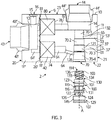
- Fig. 2 shows an embodiment of a mixing unit 9, which forms part of a cleaning device 2 according to one aspect of the invention.
- the mixing unit 9 comprises a housing 10. Inside the housing 10, the mixing unit 9 has a mixing chamber located inside an injector 100. The injector 100 is arranged inside the housing 10.
- the mixing unit utilizes the injector principle for mixing a water and one or more cleaning agent.
- the injector principle utilizes that when water is under pressure is led through a channel with a decreasing and increasing cross-sectional area (in the direction of the flow of the water) and a channel is formed to intersect the water flow chamber, then a vacuum is formed in the intersecting channel. This vacuum sucks a cleaning agent into the chamber where the water flows. There, the cleaning agent starts to mix with the water. Thus, the cleaning agent may be transported into the flowing water without the use of pumps.
- This principle is well known and will not be discussed further. Also, known in the art, is to subsequently add gas/air under pressure to the water/cleaning agent mixture in order to provide a foam.
- Fig. 2 shows a cross section of an embodiment of a mixing unit 9 for supplying foam and/or water/cleaning agent mixture and/or pure water for cleaning.
- the illustrated mixing unit 9 comprises a housing 10 having a liquid/water inlet 43 for receiving pressurized liquid/water.
- the water is supplied to the water inlet 43 via a suitable pipe, liquid supply tubing 42, as described above.
- the liquid supply tubing 42 may be connected to the mixing unit via a connector 43', which may secured to the mixing unit 9, e.g. by cooperating threading (not shown) on the mixing unit 9 and connector 43', or by other fastening means. Further, the connection may be water tight by application of a suitable gasket 43" such as an O-ring.
- the housing 10 also has a gas inlet 53 for receiving pressurized gas, preferably air from compressor 51 as described above.
- the gas inlet 53 may comprise a connector 53', allowing easy connection to the hose, tube, or pipe forming the gas piping 52 described in connection with Fig. 5 above.
- the connector 53' may be connected to the mixing device 9, e.g. by cooperating threading (not shown) on the mixing unit 9 and connector 53', or by other fastening means. Further, the connection may be water tight by application of a suitable gasket (not shown), such as an O-ring.
- the housing 10 also comprises a fluid outlet 44 for said foam and/or water/cleaning agent mixture and/or pure water.
- the fluid outlet 44 may comprise a connector 44', allowing easy connection to the hose, tube, or pipe forming the tubing of external cleaning system 310 described in connection with Fig. 5 above.
- the connector 44' may be connected to the mixing device 9, e.g. by cooperating threading (not shown) on the mixing unit 9 and connector 44', or by other fastening means. Further, the connection may be water tight by application of a suitable gasket 44'" such as an O-ring.
- the housing 10 also comprises at least one cleaning agent inlet 37.
- the cleaning agent inlet 37 may comprise a connector 37', allowing easy connection to the hose, tube, or pipe forming the cleaning agent input line described in connection with Fig. 5 above.
- the connector 37' may be connected to the mixing device 9, e.g. by cooperating threading (not shown) on the mixing unit 9 and connector 37', or by other fastening means. Further, the connection may be water tight by application of a suitable gasket (not shown) such as an O-ring.
- the cleaning agent connector 37' (or connectors) may be one-way valves in order to prevent a back flow of cleaning agent.
- the gas/air is supplied to the housing 10 via a suitable pipe 52, which is preferable connected with a compressor 51, and the first cleaning agent is supplied to the housing 10 via a suitable pipe 35, which is in fluid communication with a reservoir 33.
- the water pipe 42 is fluidly connectable to a water pump 41 for supplying pressurized water to the housing 10 of the mixing unit 9.
- the mixing unit 9 further comprises an injector 100 positioned inside the housing 10.
- the injector is received in an injector receiving bay 70 in the housing 10, as may be appreciated by comparing e.g. Figs 2 and 3 (The injector receiving bay 70 may alternatively be called an injector receiving port 70).
- Fig. 3 shows the injector 100 removed from the injector receiving bay 70
- Fig. 2 shows the injector 100 in place in the injector receiving bay 70.
- the injector 100 is in fluid communication with the fluid outlet 44 via a turbulence chamber 14 formed inside the housing 10 between the injector receiving bay 70 and the fluid outlet 44.
- the injector receiving bay 70 opens into the turbulence chamber 14.
- the turbulence chamber 14 opens into the fluid outlet 44 of the mixing unit 9. In the turbulence chamber 14 the water/cleaning agent mix is mixed with air in order to provide foam.
- the mixing unit further comprises an injector valve 40 formed within the housing 10.
- the flow of liquid (water) through the mixing unit 9 may be controlled by the injector valve 40, which is a flow control valve, i.e. a valve for controlling the magnitude or volume of water flowing there through per unit of time.
- the valve may be a ball valve, a seat valve, or any other suitable valve.
- the injector valve 40 is in fluid connection with the liquid inlet 43 via a channel 64'.
- the injector valve 40 is further in fluid connection with the injector 100 via a liquid supply channel 64, that opens into the above-mentioned injector receiving bay 70.
- the injector valve 40 is located in the mixing unit 9 in a liquid supply channel 64, 64' forming a fluid connection between the liquid inlet 43 and an injector 100 of the mixing unit 9.
- a spraying liquid valve 80 may preferably be arranged inside the housing 10 of the mixing unit 9.
- the valve may be of the same type as the injector valve 40.
- the spraying liquid valve 80 is in fluid communication with the liquid inlet 43 via a channel 81 formed in the housing 10. Further, the spraying liquid valve 80 is in fluid communication with the turbulence chamber 14, and thereby the fluid outlet 44.
- the spraying liquid valve 80 is arranged in a fluid connection 81, 82 between the liquid inlet 43 and the liquid outlet 44 of the mixing unit 9. This spraying liquid valve 80 may be used for providing clean water for spraying in the external cleaning system 300.
- the liquid inlet 43 is preferably in fluid communication with a distribution chamber 13.
- the distribution chamber opens into the liquid inlet 43.
- the channel 64' to the injector valve 40 and the channel 81 to the spraying liquid valve 80 thus extend from the distribution camber 14.
- the injector valve 40 is preferably arranged in an injector valve bay 74 (The injector valve bay 74 may alternatively be called an injector valve port 74).
- the injector valve bay 74 is arranged within the housing 10, and adapted for receiving the injector valve 40.
- the above mentioned channel 64' opens into the injector bay 74 at one (downstream) end and into the distribution chamber 13 at the other (upstream) end.
- the spraying liquid valve 80 is preferably arranged in a spraying liquid valve bay 78 (The spraying liquid valve bay 78 may alternatively be called spraying liquid valve port 78).
- the spraying liquid valve bay 78 is arranged within the housing 10, and adapted for receiving the spraying liquid valve bay 78.
- the above mentioned channel 81 opens into the spraying liquid valve bay 78 at one (downstream) end, and into the distribution chamber 13 at the other (upstream) end.
- an actuator 240 for operating the injector valve may further be arranged inside the housing, and preferably adjacent to the injector valve bay 74.
- the actuator 240 is arranged external to the mixing unit 9 housing 10, but adjacent to a sidewall thereof.
- a shaft extends from the actuator 240 to the injector valve bay 74 via a channel or passage (not shown) from the sidewall, where the actuator 240 is located, to the injector valve bay 74.
- an actuator 280 for operating the spraying liquid valve 80 may further be arranged inside the housing, and preferably adjacent to the spraying liquid valve bay 78.
- the actuator 280 is arranged external to the mixing unit 9 housing 10, but adjacent to a sidewall thereof.
- a shaft extends from the actuator 280 to the spraying liquid valve bay 78 via a channel or passage (not shown) from the sidewall, where the actuator 280 is located, to the spraying liquid valve bay 78.
- a further channel 15 may extend from the distribution chamber 13 an outlet 16 formed in a sidewall of the housing 10.
- the outlet 16 may be formed through a connector 16'.
- the connector 16' may allow easy mounting of a hose for manual cleaning in the vicinity of the mixing unit 9.
- the mixing unit may comprise more than one injector 100, such as two or three or more formed inside the housing.
- each injector may be arranged in injector receiving bay as described above and fluidly connected to a fluid outlet and to the liquid inlet as described above.
- the mixing unit 9 comprises more than one injector 100
- the mixing unit may have one injector valve 40 per injector, each arranged in an injector valve bay 74 as described above.
- a plurality of injectors may be connected to a single injector valve 40 arranged in a single injector valve bay 74, as described above.
- a selector mechanism may be integrated into the housing 10 of the mixing unit 9, the selector mechanism being arranged to switch between liquid supply channel 64 in the mixing unit leading to each of the injectors 100.
- Such a selector mechanism may further be connected to the control system 200 via an actuator, which may be integrated inside the housing 10, or be located externally thereto.
- an advantage of the mixing unit 9, the cleaning device 2 and the cleaning system 1 according to the invention is that one and only one injector is necessary.
- the at least one injector 100 and the injector valve 40 are integrated within the mixing unit housing 10.
- the cleaning agent connection channels 61, 62, 63 for fluidly connecting the at least one injector 100 and the sources of cleaning agent 33, 34 are formed within the mixing unit housing 10.
- the liquid supply channel 64 for fluidly connecting the injector valve 40 with the injector 100 is formed within the mixing unit housing 10.
- the gas supply channel 65, for fluidly connecting the gas supply valve 50 and the at least one injector 100 is formed inside the mixing unit housing 10.
- the injector 100 may be connected to a plurality of sources 33, 34 of cleaning agents.
- Figs. 2 and 3 for the sake of simplicity, only one cleaning agent connection channel 61 is shown, the leaning agent connection channel 61 extending from a cleaning agent inlet 37 of the mixing unit 9 to the injector 100.
- Fig. 5 two sources 33, 34 of cleaning agent are illustrated.
- a cleaning agent connection channel 61, 62, 63 may extend from each cleaning agent inlet 37, 38, 39, at an outer surface of the mixing unit 9 housing 10, to the injector 100.
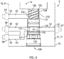
- a cleaning agent connection channel 61 may either extend directly from the cleaning agent outlet 37 to the injector 100 (actually the injector receiving bay 70) or two (or more) inlets 38, 39 may merge via cleaning agent connection channels 62, 63, into a common cleaning agent connection channel 60 formed inside the housing 10 of the mixing unit 9.
- the cleaning agent channels 61, 62, 63 in the mixing unit 9 are shown to extend from openings in different sidewalls of the mixing device. However, they may also all be formed in the same sidewall.
- the cleaning agent channels 61, 62, 63 may be distributed in a three dimensional pattern around the injector receiving bay 70.
- Fig. 2 shows the injector 100 inserted in the mixing unit 9 housing 10.
- Fig 3 shows the injector when separated from the housing. Details of the injector 100 can be appreciated from Fig. 3 . However, Fig. 14 show more details of the injector 100.
- Fig. 14 shows a section through an injector 100 according to an aspect of the invention.
- the injector 100 has an injector body 101.
- the injector body 101 is elongate, generally cylindrical in structure.
- injector 100 has a longitudinal axis A.
- the elongate injector body 101 has first end 102 and a second end 103 opposite to the first end 102.
- An elongate injector chamber 110 is formed centrally within in the injector body 101.
- the injector chamber 110 comprises two sections, a first section 111 and a second section 112 opening into an injector outlet 113.
- the injector outlet 113 is formed in an end wall 114 of the injector body 101, at the second end 103 (the outlet end of the injector 100).
- the first section 111 of the injector chamber 110 has an injector inlet 115.
- the injector inlet 115 also is in fluid connection with one or more cleaning agent bores 116, 117.
- two cleaning agent bores 116, 117 are shown in the injector body 101 extending in a direction perpendicularly to the longitudinal axis A of the injector 100.
- the injector 100 may comprise one or three, or four or more cleaning agent bores 116, 117.
- the cleaning agent bores 116, 117 does not necessarily need to be formed perpendicularly to the longitudinal axis A of the injector 100, but may more generally be formed at an angle with the longitudinal axis A, however such that the cleaning agent bores 116, 117 will intersect with the injector chamber 110 at the injector inlet 115.
- Each of the cleaning agent bores 116, 117 has an inlet 116', 117', respectively, at an outer surface 118 of the injector body 101.
- the inlet 116', 117' of the cleaning agent bores 116, 117 are formed at a place where the outer surface 118 of the injector body 101 has a circumferential groove, cleaning agent groove 119.
- the cleaning agent groove 119 forms an annular cleaning agent channel 120 (see Fig. 2 ) around the injector 100 together with the inner surface of the injector receiving bay 70 of the mixing unit 9 housing 10, when the injector 100 is inserted in the injector receiving bay 70 as shown in Fig. 2 .
- the annular cleaning agent channel 120 serves to distribute the cleaning agent.
- the cleaning agent connection channel 61 of the mixing unit housing 10 opens into the annular cleaning agent channel 120 in an inlet 121 thereto ( Figs 2 and 3 ).
- gaskets such as O-rings may be arranged in annular grooves, gasket grooves 122, 123, which are formed in the outer surface 118 of the injector body 101, and on either side of the cleaning agent groove 119.
- gaskets may instead be provided in grooves formed in the surface of the injector receiving bay 70.
- the injector comprises an injector water inlet 124.
- the injector water inlet 124 is formed as a bore from the outer surface 118 of the injector body 101 and into the injector body 101 in a transverse direction to the longitudinal axis A of the injector 100.
- the injector water inlet 124 communicates with a water inlet connection channel 125 formed in the longitudinal direction of the injector 100 (parallel to longitudinal axis A) that opens into the injector chamber 110 at the injector inlet 115.
- the injector water inlet 124 is formed at a place where the outer surface 118 of the injector body 101 has a circumferential groove, water inlet groove 126 (may also be called liquid inlet groove 126).
- the water inlet groove 126 forms an annular water inlet channel 127 (may also be called annular liquid inlet channel 127) (see Fig. 2 ) around the injector 100 together with a portion of the inner surface of the injector receiving bay 70 of the mixing unit 9 housing 10, when the injector 100 is inserted in the injector receiving bay 70 as shown in Fig. 2 .
- the annular water inlet channel 127 serves to distribute the water.
- the liquid supply channel 64 in the mixing unit housing 10 opens into the annular water inlet channel 127 in an inlet 128 thereto ( Figs 2 and 3 ).
- gaskets such as O-rings may be arranged in annular grooves, gasket grooves 122, 129, which are formed in the outer surface 118 of the injector body 101, and on either side of the water inlet groove 126.
- gaskets may instead be provided in grooves formed in the surface of the injector receiving bay 70.
- pressurized liquid preferably in the form of water
- pressurized liquid may be transported from the pump 141 via the liquid supply channel 64 in the mixing unit housing 10 into the annular water inlet channel 127 and further into the injector water inlet 124, and the water inlet connection channel 125 passing the injector inlet 115, and further into the injector chamber 110 and out the injector outlet 113.
- the pressurized water passes the injector inlet 115, a vacuum is created in the cleaning agent bores 116, 117 and further the in annular cleaning agent channel 120.
- cleaning agent will be sucked from the cleaning agent source 33, 34 into the annular cleaning agent channel 120 via the cleaning agent connection channel 61 of the mixing unit housing 10.
- water and cleaning agent is thereby mixed.
- the injector outlet 113 is fluidly connected to the fluid outlet 44 of the housing 10 via a turbulence chamber 14 formed within the housing 10. As illustrated in e.g. Fig. 14 , the injector inlet 115 has a narrower cross section than the cross section of the injector outlet 113.
- the outer surface 118 of the injector body 101 has a further circumferential groove, gas groove 130.
- the gas groove 130 forms an annular gas inlet channel 131 (see Fig. 2 ) around the injector 100 together with a portion of the inner surface of the injector receiving bay 70 of the housing 10 of the mixing unit 9, when the injector 100 is inserted in the injector receiving bay 70 as shown in Fig. 2 .
- the annular gas inlet channel 131 serves to distribute the gas (air). Further it is clear that gas supply channel 65 in mixing unit housing 10 opens into the annular gas inlet channel 131 in an inlet 132 thereto ( Figs 2 and 3 ).
- the annular gas inlet channel 131 is in fluid communication with the turbulence chamber 14, via one or more helical grooves 133 formed in the outer surface 118 of a portion 134 of the injector body 101, and via a gap 135 between a cylindrical end portion 136 at the second (outlet) end 103 of the injector body and the inner surface of the injector receiving bay 70.
- the one or more helical grooves 133 formed in the outer surface 118 forms a helical channel 137 between the helical groove 133 and the inner surface of the injector receiving bay 70, when the injector is in place in the injector receiving bay 70 as shown in Fig. 2 .
- the helical grooves 133 and the gap 135 forms a swirling stream of gas (air) around the stream of water and cleaning agent mixture exiting from the injector outlet 113.
- this provides an improved foaming effect.
- helical grooves 133 are only used in certain aspects of the invention. In other aspects of the invention an acceptable foaming effect may be obtained using other types of gas (air) injection as mentioned above.
- the helical grooves may alternatively be formed in the surface of the injector receiving bay 70 (not shown).
- the injector 100 When, as described above, the injector 100 has an injector water inlet 124 formed in a direction transverse to a longitudinal axis A of the injector 110 it allows the insertion and retraction of the injector 100 from the housing 10 of the mixing unit 9, through a wall 22 thereof.
- the injector instead of the cleaning device comprising numerous injectors, with various capacities for providing foam and/or water/cleaning agent mixture, the injector may instead easily be exchanged with another injector 100 with a different capacity.
- the maximum dimension d1 and d2 of the injector body 101 at the first end 102 and at the outlet end 103 is the largest cross sectional extent (perpendicular to the longitudinal axis A) of the injector body at those locations.
- the injector body 101 is cylindrical, or formed from generally cylindrical portions 134, 136, 143, 144, 145. In that case the maximum dimensions corresponds to diameters.
- the maximum dimension d1 at the first end 102 is the dimension (diameter) of the portion 145 of the injector body.
- the maximum dimension d2 at the outlet end 103 is the dimension (diameter) of the portion 134 of the injector body 101, wherein the helical grooves 133 are formed.
- the injector body 101 only having a decreasing maximum dimension from the first end 102 to the outlet end 103, is meant that none of the portions 144, 143, in between the two maximum dimension d1 and d2 exceeds that of a previous portion as seen from the first end 102 to the outlet end 103.
- the above-mentioned grooves 119, 126, 130 and the gasket grooves 122. 123, 129 are not counted with.
- the gaskets (O-rings) 138, 139, 140 are not counted either as these are at least partly compressible.
- the injector body 101 comprising means for releaseably connecting the injector 100 to a portion 70 (such as the injector bay/port 70) of the housing 10 of the mixing unit 9 is meant e.g. that one or more of the cylindrical portions 143, 144, or 145 may be provided with means such as a threading (141, not shown in Fig. 14 ), which is configured to cooperate with connection means, such as corresponding threading (142 not shown in Fig. 14 ) in a section of the injector receiving bay 70 in the mixing unit 9.
- connection means such as corresponding threading (142 not shown in Fig. 14 ) in a section of the injector receiving bay 70 in the mixing unit 9.
- other connection means known in the art may be used e.g. latches, bayonet fixtures, etc.
- the injector receiving bay 70 comprises sections 70-1, 70-2, 70-3 and 70-4 of increasing maximum dimensions from the end at the turbulence chamber 14 to the opposite end.
- the mixing unit housing 10 is preferably formed as a solid block 11 of material, and the at least one injector 100 is arranged in an injector receiving bay 70 which is formed as a bore in the block 11. Further, the injector valve 40, is arranged in an injector receiving bay 74 formed as a bore in the block 11). Yet further, the cleaning agent connection channels 61, 62, 63, the water supply channel 64 and the gas supply channel 65 are preferably formed as bores in the block 11.
- the housing 10 is formed from a solid block 11 of a uniform material as an integrated unit.
- the illustrated mixing unit 9 may preferably be manufactured from a metal alloy, e.g. stainless steel.
- a robust mixing unit 9 which can withstand pressures up to 60 bar without malfunction or any noticeable leakage may be obtained. Also, it is obtained that weldings may be omitted or reduced in relation to the fluid connections of the cleaning device 2.
- the bores mentioned above and below are channels, which may be formed in the block 11 by drilling out the bores and/or they may be formed by e.g. a molding process.
- the block 11 may as shown in Figs 4A and B be an elongate box shaped structure, having two end surfaces 20, 21 and four side surfaces 22, 23, 24, 25. However, in not shown embodiments, the block 11 may have other shapes e.g. cylindrical.
- the injector 100 may be arranged in a bore of stepwise decreasing maximum dimension (injector receiving bay 70) in the block 11, this bore being provided in one side surface (a bottom surface) 22 of the block 11.
- the fluid outlet 44 of the mixing unit 9 may be provided through an opposite side surface 23 (top surface).
- the turbulence chamber 14 is preferably provided as a bore through this side surface 23.
- the cleaning agent connection channel 61, 62, 63, and the gas supply channel 65 may preferably be formed as bores through on or both of further sidewalls 24, 25, as are the bores for shafts for connecting the actuators 240, 280 to the injector valve 40 and the spraying liquid valve 80, respectively.
- the injector valve 40 and the spraying liquid valve 80 are, as described above, arranged in an injector valve bay 74 and a spraying liquid valve bay 78, respectively.
- These bays 74, 78 may, in not shown embodiments, be formed as bores through one of the free sidewalls 22, 23, 24, 25.
- the block 11 may preferably comprise a main block portion 11' and a lid block portion 11".
- the lid block portion 11" may be provided in extension of an end wall 20' of the main block portion 11'.
- the lid block portion 11" is preferably formed in the same material as the main block portion 11'.
- the distribution chamber 13, the liquid inlet 43, and the channels 81 and 64' are preferably provide as bores in the lid block portion 11".
- the injector valve bay 74 and a spraying liquid valve bay 78 are then formed as bores in through the main block portion 11', and the lid block portion 11" is then used to secure the injector valve 40 and the spraying liquid valve 80 in the injector valve bay 74 and a spraying liquid valve bay 78.
- the lid block portion 11" may be connected to the main portion 11' by use of suitable fasteners, such as bolts (not shown).
- the injector 100 may preferably comprise a tool receiving lock 146 arranged at the portion 145 of the injector 100 at the first end thereof.
- the tool receiving lock 146 is preferably formed as a depression in the end wall 104 of the injector 100, opposite the injector outlet 113.
- the tool receiving lock 146 has a polygonal cross sectional shape (in a plane perpendicular to the longitudinal axis A), e.g. a hexagonal shape.
- the tool receiving lock 146 may thereby allow rotation of the injector by a tool (not shown) having a correspondingly shaped cross-sectional shape. Thereby, the injector may be secured in the injector receiving bay 70 - or released therefrom.
- Figs. 7A-F shows the injector 100 in various positions relative to the injector receiving bay 70 in mixing unit 9.
- the injector 100 is inserted totally into the injector receiving bay 70 of the mixing unit 9, and is ready for use.
- Fig. 7B the injector 100 has been released from the mating connection means, and has been slightly displaced relative to the housing 10.
- the injector 100 has been further displaced away from is connected location.
- Fig. 7D the injector is seen completely removed from the injector receiving bay 70.
- the corresponding shapes dimension of sections of the injector 100 and the injector receiving bay 70
- FIGs. 7E and 7F the injector 100 and the housing 10 is again seen in a disassembled ( Fig. 7E ) and an assembled state ( Fig. 7F ).
- Fig. 7E the injector 100 and the housing 10 is again seen in a disassembled
- Fig. 7F an assembled state
- the above-mentioned hexagonal shape of a tool receiving lock 146 is clearly visible.
- Fig. 8 in a partly sectional, perspective view, shows an embodiment of the housing 10 of the mixing unit 9 according to a further aspect of the invention, where the cleaning device 2 further comprises means for rinsing the inlet 121 of a cleaning agent connection channel 61, 62, 63 of the mixing unit 9 housing 10, where the cleaning agent connection channel 61, 62, 63 opens into the injector receiving bay 70, or more particularly. where the cleaning agent connection channel 61, 62, 63 opens into the annular cleaning agent channel 120 formed between the injector receiving bay 70 and cleaning agent groove 119, when the injector is inserted in the injector receiving bay 70, as described above.
- Fig. 8 shows that the housing 10 of the mixing unit 9 may be substantially as described above.
- Fig. 8 also shows an injector 100, which is partly released from the injector receiving bay 70.
- Also shown in the figure are three cleaning agent connectors 37', 38', 39' corresponding to those described above and arranged in inlets 37, 38, 39 of cleaning agent connection channels 61, 62, 63, respectively.
- the cleaning agent connection channels 61, 62, 63 converge into a common cleaning agent connection channel 60 as is described above in connection with Fig. 6 .
- the rinsing system may also be applied to embodiments, where the cleaning agent connection channels 61, 62, 63 are individual channels.
- a rinsing channel 66 for providing rinsing water to the area around the connection 121.
- the water is provided via a source of water 49, which is preferably the same pump 41 as described above.
- the pump 41 has a fluid connection to a rinsing valve (not shown in Fig. 8 ), which may be provided inside the housing 10, or externally.
- This rinsing valve is operated by an actuator 290, which may be connected to the control unit 201 of the control system either by suitable cable or wirelessly (not shown in Fig. 5 ).
- an actuator 290 which may be connected to the control unit 201 of the control system either by suitable cable or wirelessly (not shown in Fig. 5 ).
- Fig. 9 illustrates a more preferred embodiment of a rinsing function for a cleaning device according to this aspect of the invention.
- Fig. 9 shows a section through a mixing device 9 with an injector 100, basically as described above in connection to Figs. 2-7F and Fig. 14 .
- a cleaning agent connector 37' is arranged in a cleaning agent inlet 37 of the mixing unit 9.
- the cleaning agent connector 37' is preferably connected to a cleaning agent valve 30 as described in connection with Fig. 5 above, and via a suitable tubing, such as a rubber or plastic tubing.
- a suitable tubing such as a rubber or plastic tubing.
- the rinsing function is provided by the cleaning device 2 having the function build into a control system 200 as described above, wherein the control system 200 is connected to the actuators 230, 232 of the cleaning agent valve 30, 31, and wherein the control unit 201 is connected to the actuator 240 of the injector valve 40, and where the control system 200 is configured to shut of the cleaning agent valve 30, 31, while - at the same time - controlling the actuator 240 of the injector valve 40 to pulse the water flow through the injector 100, i.e. to turn on and off the water flow through the injector 100.
- This provides a flow back and forth in the cleaning agent connection channels 61, 62, 63.
- the one or more cleaning agent valves 30, 31 are closed. Consequently, the cleaning agent(s) is prevented from flowing to the injector 100, while water is still allowed to flow through the injector 100 (in pulses). Thereby, a pulsing suction is provided in the cleaning agent connection channels 61, 62, 63 inside the mixing unit 9, but possibly also in the tubing 35, 36, and a part of the cleaning agent residues in the cleaning agent connection channels 61, 62, 63 and/or in the tubing 35, 36, will be sucked into and through the injector 100, and into the tubing 310 of external cleaning system 300.
- the previously described rinsing function may be implemented in a method for operating a cleaning device 2 as described above, and where the method comprises the steps of closing a cleaning agent valve 30, 31, while controlling the actuator 240 of the injector valve 40 to pulse the water flow through the injector 100.
- FIG. 10 a generalization of the cleaning system 1 of Fig. 5 is shown.
- the figure illustrates a function for preventing so-called water hammering.
- hammering may be reduced by shutting down valves such as the injector valve 40 slowly.
- valves such as the injector valve 40
- users of a cleaning system 1 may freely exchange valves as they see fit, a manufacturer of a cleaning system 1 may not control the closing rate of all valves. Consequently, the water hammering may be significant in practical systems.
- the injector valves 40 and outlet valves 321, 322, 323, described in connection with the cleaning system 1 above, may be adapted to minimize water hammering when leaving the factory. But, if the valves are replaced at the customer side, water hammering may again become a problem. Therefore, there is a need to build-in a function that may reduce water-hammering in cleaning systems 1, such as described above.
- the problem may be solved by a suitable control implemented in the control system 200 of the cleaning system 1 described above.
- this control system 200 knowledge of the times at which the individual valves are to be opened and closed is built-in. As a consequence, it will be possible to regulate the pressure a short interval of time before a scheduled or intended closing of a particular valve.
- the control involves regulating the pressure provided by pump 41, alternatively stopping the pump 41 all-together, a number of seconds, such as 1-10 seconds, preferably such as 1-5 seconds, before a valve is to be closed.
- a number of seconds such as 1-10 seconds, preferably such as 1-5 seconds
- By this regulation it will be possible to reduce the velocity of the water flow in a branch 310, 311, 312, 313 of a fluid distribution system, such as the system 300, shown in Fig. 10 , or the extended cleaning system 300 of Fig. 5 . Thereby, the water hammering is minimized, and a prolonged life of the components of the cleaning system may be obtained.
- FIG. 11 is a partly sectional, perspective view through a housing 10 of a mixing unit and an injector.
- the housing 10 is sectioned at the injector receiving bay 70, and the injector 100 is shown un-sectioned and in perspective.
- the swirling air is represented by the arrows 400, 401, 402, 403.
- Gas (air) is injected via the gas supply channel 65 in the mixing unit 9, as indicated by the arrow 404, and entered into the annular gas inlet channel 131 formed between the inner surface of injector receiving bay 70 and the gas groove 130 in outer surface 118 of injector body 101, as explained above in connection with Fig. 14 .
- Cleaning agent is sucked into the injector 100 via the first cleaning agent connection channel 61 as indicated by arrow 405.
- water is injected into the injector 100 via liquid supply channel 64, as indicated by the arrow 406 in Fig.11 .
- the water and cleaning agent will mix in the injector chamber 110 and exit mixed through the injector outlet 113 as indicated by the arrow 407 in Fig. 10 .
- a threading 141 on the portion 145 of the injector 100 is clearly illustrated, the threading 141 cooperating with a corresponding threading 142 on the inside surface of the injector receiving bay 70 of the housing 10.
- Fig 13 this figure shows details of the portion 134, in which the helical grooves 133 are located. From the figure, it may appreciated that a helical channel 137 is formed between the helical groove 133 and the inner surface of the injector receiving bay 70. At least one such channel 137 is formed, but preferably a plurality of channels 137 are formed. In the shown embodiment, and as most clearly visible in Fig. 12 , four channels 137 are formed. Also, clearly visible in Fig. 13 is the inlet 132 from the gas supply channel 65 of the mixing unit 9. Also, Fig.
- outlet 113 in the end wall 114 of the injector body 101 at outlet/second end 103 of injector body 101 is formed on a platform provided by the cylindrical portion 136, which extends further in the direction of the second end 103, than the portion 134 with the helical groove 133.
- a small gap 135 is provided between injector receiving bay 70 and the outer surface 118 of the injector body 101 of the cylindrical portion 136. This gap 135 allows to format the swirling air flow around the injector outlet 113, before the air flow enters the turbulence chamber 14.
- the portion 136 of the body 101 of the injector 100 is shown and described as a cylindrical object.
- a sidewall 105 may show an outward taper in the direction from the first end 102 towards the second end 103 of the portion 136 of the body 101 of the injector 100.
- the portion 136 would appear to have a conical section. This may aid in dimensioning the airflow.
- the diameter d4 of the portion 136 at the end wall 114 may thereby be increased to minimize the gap 135. This may limit/control the air-flow through the gap 135, while still allowing the swirl to create and develop in the space of the gap 135.
- FIG. 12 the figure shows a front view of an injector 100 inserted in the injector receiving bay 70 of a mixing unit. 9.
- the turbulence chamber 14 is the outmost facing surface.
- the inner circle of the figure shows the injector inlet 115.
- the next circle outward indicates the injector outlet 113.
- the area between this circle and the next is the top surface 114 of the cylindrical portion 136, which forms the aforementioned extension ahead of the portion 134 where the helical grooves 133 are formed.
- the helical grooves 133 and thereby the helical channels 137 are shown with their exit into the gap135.
- the injector 100 is positioned within the mixing unit 9 for providing a gap 135 around the injector outlet 132.
- This gap 135 is fluidly connected to the gas inlet 53 of the housing 10 for allowing gas (air) to pass between the injector outlet 132 and a portion of the injector receiving bay 70 of the housing 10 and mix with the first cleaning agent and water mixture at the turbulence chamber 14 and/or the fluid outlet 44 of the housing 10 to form foam.
- the ratio between the cross sectional area of the injector outlet and the cross sectional area of the helical channels 137 must remain constant, in order to obtain the same quality of foam, at different quantities.
Landscapes
- Chemical & Material Sciences (AREA)
- Chemical Kinetics & Catalysis (AREA)
- Cleaning By Liquid Or Steam (AREA)
- Nozzles (AREA)
Applications Claiming Priority (1)
| Application Number | Priority Date | Filing Date | Title |
|---|---|---|---|
| DKPA201600689A DK179376B1 (en) | 2016-11-08 | 2016-11-08 | Compact cleaning device |
Publications (1)
| Publication Number | Publication Date |
|---|---|
| EP3342490A1 true EP3342490A1 (de) | 2018-07-04 |
Family
ID=62144909
Family Applications (1)
| Application Number | Title | Priority Date | Filing Date |
|---|---|---|---|
| EP17200606.6A Withdrawn EP3342490A1 (de) | 2016-11-08 | 2017-11-08 | Kompakte reinigungsvorrichtung und verfahren zum betreiben der reinigungsvorrichtung |
Country Status (2)
| Country | Link |
|---|---|
| EP (1) | EP3342490A1 (de) |
| DK (1) | DK179376B1 (de) |
Cited By (2)
| Publication number | Priority date | Publication date | Assignee | Title |
|---|---|---|---|---|
| CN112438663A (zh) * | 2019-08-29 | 2021-03-05 | 添可智能科技有限公司 | 清洁设备 |
| WO2025219933A1 (en) * | 2024-04-17 | 2025-10-23 | Fraga Pedro | An automatic and modular spraying system |
Citations (6)
| Publication number | Priority date | Publication date | Assignee | Title |
|---|---|---|---|---|
| DE3938981C1 (de) * | 1989-11-23 | 1991-04-11 | Grace Service Chemicals Gmbh, 6900 Heidelberg, De | |
| US20040040102A1 (en) * | 2001-07-30 | 2004-03-04 | Tennant Company | Foamed cleaning liquid dispensing system |
| US20100024842A1 (en) * | 2008-08-04 | 2010-02-04 | Arnold Kholodenko | Generator for foam to clean substrate |
| AT11728U1 (de) * | 2010-04-16 | 2011-04-15 | Abdula Kurkayev | Mischvorrichtung |
| CA2713643A1 (en) * | 2010-08-24 | 2012-02-24 | Basf Corporation | Two component foam dispensing apparatus |
| WO2014091275A1 (en) * | 2012-12-10 | 2014-06-19 | Nilfisk-Advance A/S | Cleaning device |
Family Cites Families (2)
| Publication number | Priority date | Publication date | Assignee | Title |
|---|---|---|---|---|
| DE2445689A1 (de) * | 1974-09-25 | 1976-04-01 | Fink Chemie | Geraet zum aufschaeumen von fluessigkeiten, insbesondere von wasser mit chemikalien zu reinigungszwecken |
| DE10342000A1 (de) * | 2003-09-08 | 2005-04-07 | Alfred Kärcher Gmbh & Co. Kg | Verfahren zum Erzeugen eines Reinigungsmittelschaumes sowie Schaumerzeugungssystem zur Durchführung des Verfahrens |
-
2016
- 2016-11-08 DK DKPA201600689A patent/DK179376B1/en active
-
2017
- 2017-11-08 EP EP17200606.6A patent/EP3342490A1/de not_active Withdrawn
Patent Citations (6)
| Publication number | Priority date | Publication date | Assignee | Title |
|---|---|---|---|---|
| DE3938981C1 (de) * | 1989-11-23 | 1991-04-11 | Grace Service Chemicals Gmbh, 6900 Heidelberg, De | |
| US20040040102A1 (en) * | 2001-07-30 | 2004-03-04 | Tennant Company | Foamed cleaning liquid dispensing system |
| US20100024842A1 (en) * | 2008-08-04 | 2010-02-04 | Arnold Kholodenko | Generator for foam to clean substrate |
| AT11728U1 (de) * | 2010-04-16 | 2011-04-15 | Abdula Kurkayev | Mischvorrichtung |
| CA2713643A1 (en) * | 2010-08-24 | 2012-02-24 | Basf Corporation | Two component foam dispensing apparatus |
| WO2014091275A1 (en) * | 2012-12-10 | 2014-06-19 | Nilfisk-Advance A/S | Cleaning device |
Cited By (3)
| Publication number | Priority date | Publication date | Assignee | Title |
|---|---|---|---|---|
| CN112438663A (zh) * | 2019-08-29 | 2021-03-05 | 添可智能科技有限公司 | 清洁设备 |
| CN112438663B (zh) * | 2019-08-29 | 2022-08-26 | 添可智能科技有限公司 | 清洁设备 |
| WO2025219933A1 (en) * | 2024-04-17 | 2025-10-23 | Fraga Pedro | An automatic and modular spraying system |
Also Published As
| Publication number | Publication date |
|---|---|
| DK179376B1 (en) | 2018-05-28 |
| DK201600689A1 (en) | 2018-05-22 |
Similar Documents
| Publication | Publication Date | Title |
|---|---|---|
| CN102369411B (zh) | 用于清洁管道的清洁系统 | |
| GB2311333A (en) | Dual aspirator | |
| JP4890722B2 (ja) | 放出/濯ぎガン | |
| KR101893809B1 (ko) | 분사노즐 및 필터의 자동 막힘 제거가 가능한 자동 분무시스템 | |
| EP2859820A1 (de) | Selbstreinigende Milchschäumungsvorrichtung | |
| CN109312894B (zh) | 润滑脂更换方法和润滑脂抽吸装置 | |
| EP2928620A1 (de) | Reinigungsvorrichtung | |
| DK201600689A1 (en) | Compact cleaning device | |
| EP3332881A1 (de) | Injektorspülfunktion | |
| JP2018047019A (ja) | 口腔洗浄装置用ノズルおよび口腔洗浄装置 | |
| EP3320965B1 (de) | Mischeinheit mit auswechselbarem injektor | |
| KR101882139B1 (ko) | 덕트청소용 에어 및 액체공급분사제어기 | |
| EP3065851B1 (de) | Reinigungseinheit und verfahren zur verbesserten herstellung von schaum für reinigungszwecke | |
| DK179381B9 (en) | CLEANING SYSTEM WITH PIPE PROTECTION FUNCTION | |
| DK179382B1 (en) | Mixing unit and injector for foam production | |
| JP5085791B1 (ja) | 噴霧装置 | |
| EP0396542B1 (de) | Waschvorrichtung und Spülgerät zur Herstellung von Schaum | |
| US20080191052A1 (en) | Supply System | |
| KR100577351B1 (ko) | 클리닝 장치의 거품 발생기 | |
| CN220371839U (zh) | 基站的污水箱及基站 | |
| US20220046932A1 (en) | Apparatus for Mixing Powdery Baking Ingredients with Water | |
| JP6588780B2 (ja) | 噴射ノズル及びこの噴射ノズルを備えた噴射装置 | |
| CN217723416U (zh) | 一种清洁装置的出水结构及清洁装置 | |
| KR102942514B1 (ko) | 치과용 핸드피스 오일 주입기 | |
| KR102883801B1 (ko) | 튜브 세정 장치 및 이를 이용한 튜브 세정 방법 |
Legal Events
| Date | Code | Title | Description |
|---|---|---|---|
| PUAI | Public reference made under article 153(3) epc to a published international application that has entered the european phase |
Free format text: ORIGINAL CODE: 0009012 |
|
| AK | Designated contracting states |
Kind code of ref document: A1 Designated state(s): AL AT BE BG CH CY CZ DE DK EE ES FI FR GB GR HR HU IE IS IT LI LT LU LV MC MK MT NL NO PL PT RO RS SE SI SK SM TR |
|
| AX | Request for extension of the european patent |
Extension state: BA ME |
|
| STAA | Information on the status of an ep patent application or granted ep patent |
Free format text: STATUS: THE APPLICATION IS DEEMED TO BE WITHDRAWN |
|
| 18D | Application deemed to be withdrawn |
Effective date: 20190105 |