EP3342504A1 - Procédé de fonctionnement d'un dispositif rivetage, dispositif de rivetage et embout pour dispositif de rivetage - Google Patents
Procédé de fonctionnement d'un dispositif rivetage, dispositif de rivetage et embout pour dispositif de rivetage Download PDFInfo
- Publication number
- EP3342504A1 EP3342504A1 EP17202963.9A EP17202963A EP3342504A1 EP 3342504 A1 EP3342504 A1 EP 3342504A1 EP 17202963 A EP17202963 A EP 17202963A EP 3342504 A1 EP3342504 A1 EP 3342504A1
- Authority
- EP
- European Patent Office
- Prior art keywords
- setting unit
- rivet
- mouthpiece
- punch
- storage container
- Prior art date
- Legal status (The legal status is an assumption and is not a legal conclusion. Google has not performed a legal analysis and makes no representation as to the accuracy of the status listed.)
- Withdrawn
Links
- 238000000034 method Methods 0.000 title claims abstract description 24
- 238000005304 joining Methods 0.000 claims abstract description 45
- 238000003860 storage Methods 0.000 claims abstract description 36
- 238000004080 punching Methods 0.000 claims description 3
- 238000003780 insertion Methods 0.000 claims 1
- 230000037431 insertion Effects 0.000 claims 1
- 230000010355 oscillation Effects 0.000 description 2
- 238000003825 pressing Methods 0.000 description 2
- 238000002604 ultrasonography Methods 0.000 description 2
- 230000008878 coupling Effects 0.000 description 1
- 238000010168 coupling process Methods 0.000 description 1
- 238000005859 coupling reaction Methods 0.000 description 1
- 230000001419 dependent effect Effects 0.000 description 1
- 230000000694 effects Effects 0.000 description 1
- 238000002955 isolation Methods 0.000 description 1
- 238000000926 separation method Methods 0.000 description 1
- 230000007704 transition Effects 0.000 description 1
Images


Classifications
-
- B—PERFORMING OPERATIONS; TRANSPORTING
- B21—MECHANICAL METAL-WORKING WITHOUT ESSENTIALLY REMOVING MATERIAL; PUNCHING METAL
- B21J—FORGING; HAMMERING; PRESSING METAL; RIVETING; FORGE FURNACES
- B21J15/00—Riveting
- B21J15/02—Riveting procedures
- B21J15/025—Setting self-piercing rivets
-
- B—PERFORMING OPERATIONS; TRANSPORTING
- B21—MECHANICAL METAL-WORKING WITHOUT ESSENTIALLY REMOVING MATERIAL; PUNCHING METAL
- B21J—FORGING; HAMMERING; PRESSING METAL; RIVETING; FORGE FURNACES
- B21J15/00—Riveting
- B21J15/10—Riveting machines
- B21J15/12—Riveting machines with tools or tool parts having a movement additional to the feed movement, e.g. spin
-
- B—PERFORMING OPERATIONS; TRANSPORTING
- B21—MECHANICAL METAL-WORKING WITHOUT ESSENTIALLY REMOVING MATERIAL; PUNCHING METAL
- B21J—FORGING; HAMMERING; PRESSING METAL; RIVETING; FORGE FURNACES
- B21J15/00—Riveting
- B21J15/10—Riveting machines
- B21J15/30—Particular elements, e.g. supports; Suspension equipment specially adapted for portable riveters
- B21J15/32—Devices for inserting or holding rivets in position with or without feeding arrangements
Definitions
- the present invention relates to a method for operating a punch riveting apparatus, as well as such a punch riveting apparatus and a mouthpiece for such a punch riveting apparatus.
- Joining methods such as riveting methods, are used to join at least two components that are particularly flat in a connection region (joint partner).
- a punch riveting method is characterized, for example, by the fact that pre-punching of the components to be joined together is not required. Rather, a rivet is pressed as a joining element by means of a joining tool, which includes a stamp in the joining direction at least two components in a joining direction, which can be ensured by a correspondingly shaped counter-holder, for example.
- a joining tool which includes a stamp in the joining direction at least two components in a joining direction, which can be ensured by a correspondingly shaped counter-holder, for example.
- the rivet or components deform in a particular manner to produce a positive and positive connection between the components.
- a so-called ultrasonic punch riveting method in which a vibration generator, such as an ultrasonic generator, is used to cause one or more components to vibrate when connecting the components.
- a vibration generator such as an ultrasonic generator
- the expended force is reduced to push the rivet.
- the invention is based on a method for operating a punch rivet device, which has a setting unit, by means of which a rivet can be held, and which has a ram, by means of which the rivet can be acted upon with force and introduced into at least one component in the joining direction in a riveting operation, having.
- rivets can be performed in a predefined orientation.
- the profile hose can then be connected at a suitable location in the joining tool, so that in each case a rivet can be supplied in the desired position or inserted into the joining tool for a riveting operation.
- the rivets can be introduced after a separation, for example by means of compressed air in the joining tool.
- the joining tool has in addition to the stamp usually a so-called. Hold-down, which surrounds the punch and serves to guide the rivet during the riveting process.
- the hold-down device acts on the component while the punch is moved relative to the hold-down in order to press the rivet into the component (or the components).
- the setting unit in particular also the punch, a correspondingly long and thin portion on the component side end (or the joining tool can be formed accordingly), so that in the mentioned possibilities for feeding and receiving the rivet in the setting unit in addition to the connection the corresponding components, so for example, the belt or the profile hose, in the area between the point of connection and the component sufficient space remains to ensure sufficient accessibility for a variety of activities.
- the setting unit for introducing the rivet is placed in the setting unit in a basic position in which one of the at least one Component facing mouthpiece of the setting unit of a region in which the at least one component is to be positioned during the riveting process, is spaced.
- a storage container structurally separate from the setting unit, in which the rivet is located, is moved to the setting unit and the rivet is automated from the storage container into the mouthpiece, in particular by a movement of the storage container or a handling component (eg slide, Plunger or similar) introduced.
- the rivet can then be held in the mouthpiece, for example, by magnetic force and / or negative pressure and / or suitable holding elements.
- the storage container can be removed from the setting unit.
- the setting unit for introducing the rivet is brought into the at least one component by means of a linear movement from the basic position in a joining position in which the mouthpiece rests against one of the components.
- the proposed solution thus no longer requires connection of a belt, a profile hose or the like to the setting unit, which means that accessibility remains ensured both when the rivet is received or inserted and during the riveting operation, even if the setting unit is shorter and / or shorter. or wider than conventional punch riveting devices.
- the rivet in the storage container which may in particular be a magazine, held by means of a holding or guiding device in a predetermined position when the rivet is introduced into the setting unit.
- a rail may be used which has a contour adapted to a profile of the rivet.
- the storage container or the handling component for introducing the rivet into the mouthpiece is moved in a direction of movement substantially perpendicular to the joining direction.
- a suitable embodiment of the mouthpiece is advantageous, that is, for example, it may be provided a suitable lateral opening.
- Such a movement is very easy to reproduce, resulting in the most accurate positioning of the rivet in the mouthpiece or an accurate introduction into the mouthpiece.
- the setting unit is brought by a linear movement of the setting unit parallel to the joining direction of the basic position in the joining position (and in particular also back again).
- the movement can be made even more reproducible and performed in particular by means of existing drives and guides or bearings.
- an ultrasonic punch riveting apparatus in which oscillations are generated by means of a vibration generator, which are coupled to the stamp, since here, as already mentioned, the advantages to be achieved are particularly large, in particular in terms of space or accessibility in the joining area.
- the invention furthermore relates to a punch riveting apparatus having a setting unit, in which setting unit a rivet can be held, which has a punch, by means of which the rivet can be acted upon by force and introduced into at least one component in the joining direction in a riveting operation, and with one of the set unit structurally separate storage container in which the rivet is available.
- the setting unit can be brought into a basic position in which a mouthpiece of the setting unit facing the at least one component is spaced from a region in which the at least one component is to be positioned during the riveting operation, wherein in the basic position the storage container is so is movable to the setting unit, that the rivet from the storage container into the mouthpiece can be introduced.
- the storage container is removable from the setting unit, and the setting unit can be brought by means of a linear movement from the basic position in a joining position (and in particular also back), in which the mouthpiece rests against one of the components.
- the invention further relates to a mouthpiece for a setting unit of a punch riveting device.
- the mouthpiece has a lateral opening and is set up such that a rivet can be introduced from the storage container structurally separate from the setting unit through the lateral opening into the mouthpiece.
- FIG. 1 schematically a conventional punch rivet 10 'is shown.
- the punch riveting device 10 ' has a frame 60, which is preferably in the form of a C-frame or C-bracket, on which the individual components are usually arranged in a punch riveting in order to take the desired position to each other.
- the frame 60 By way of the frame 60, the punch riveting device 10 'can be fastened, for example, to an arm for movement in space.
- the punch riveting apparatus 10 ' has a punch 15', by way of example with a round cross section.
- the punch 15 ' is radially surrounded by a (sleeve-shaped) hold-down 16 and arranged movable relative to this in the longitudinal direction.
- the punch 15 'and the hold-down 16' together form a setting unit 70 '.
- the punch 15 ' is coupled to a drive 50 which serves to apply a force F required to press the rivet 20 into the two components 11, 12.
- the drive 50 can be controlled, for example, by means of the arithmetic unit 95.
- the drive 50 can be, for example, a drive with ball, roller or planetary screw drive or the like which is suitable for applying a force F for pressing in a rivet 20 as a joining element into the components 11, 12.
- the hold-down 16 ' is adapted to press against the surface of the die 15 facing the component 11 with a hold-down force.
- a separate drive can be provided.
- the hold-down may also be coupled (as shown here) to the drive of the punch or to the punch itself, for example by means of a spring.
- a counter-holder in the form of a die 18 is arranged on the stamp 15 'and the hold-down 16' opposite side of the two components 11, 12, a counter-holder in the form of a die 18 is arranged.
- the punch 15 'and the die 18 are arranged in the vertical direction, as well as the hold-down 16', movable and relatively movable.
- the hold-down 16 'and the die 18 serve to clamp or compress the two components 11, 12 between the hold-down 16 'and the die 18 during processing by the punch 15'.
- the rivet 20 here by way of example a half-tubular rivet, preferably consists of a material which is harder than the materials of the two components 11, 12, at least in the region of a rivet shank.
- the component 11 facing away from the flat top of the rivet is arranged in operative connection with the punch 15 ', which rests flat against the top of the rivet 20.
- a profile tube 17 is attached to the hold-down 16 ', which serves to supply the rivet. Rivets can be introduced individually into the joining tool 70 via the profile hose, so that a new rivet is available for each new riveting operation.
- both the punch 15' and the blank holder 16 ' are relatively thin and long.
- FIG. 2 schematically a punch rivet 10 according to the invention is shown in a preferred embodiment, here as ultrasonic punch riveting, which can also be used for a method according to the invention.
- the ultrasonic punch riveting apparatus 10 corresponds to the basic structure of FIG FIG. 1 shown conventional punch rivet 10 ', in this regard, reference is also made to the description there.
- a vibrator in the form of a vibration converter 30 is provided with a signal generator 32 which together serve to generate ultrasound.
- the ultrasonic punch riveting apparatus 10 has a punch 15, which here also serves as a sonotrode, by way of example with a round cross section.
- the punch 15 is operatively connected via a so-called.
- Booster 31 with the vibration converter 30, so that the ultrasonic vibrations to the punch 15 and thus the rivet 20 are transferable.
- ultrasonic vibrations with an amplitude (distance between the maximum positive and negative amplitude of a vibration) between 10 microns and 110th ⁇ m (corresponds to an amplitude of 5 ⁇ m to 55 ⁇ m) and a frequency between 15 kHz and 35 kHz or possibly also higher.
- the signal generator 32 is connected to the arithmetic unit 95 and can be controlled by this.
- a frame 35 is attached to which the vibration converter 30, the booster 31 and the punch or the sonotrode 15 are arranged.
- the punch or sonotrode is here only at a lower, i. the components facing portion formed relatively thin.
- the punch 15 is also radially surrounded by a hold-down 16 and arranged to be movable relative to this in the longitudinal direction, wherein the hold-down expands according to the punch 15 upwards.
- the hold-down is here attached by way of example by means of a spring on the frame 35.
- the punch 15 is coupled to a drive 50, which serves to apply a force F required for pressing in the rivet 20 into the two components 11, 12.
- the drive 50 can be controlled, for example, by means of the arithmetic unit 95.
- the punch 15 and the hold-down 16 in this case form a set unit 70, wherein the components 11, 12 facing the end into which the rivet 20 is received, also referred to as mouthpiece 71.
- a storage container 80 is shown in which rivets can be provided, which can also be introduced into the mouthpiece 71.
- the storage container can be moved by means of a suitable actuator.
- the storage container 80 can be arranged on the frame 60, then there, for example, with a suitable actuator, but it can also be positioned elsewhere in the processing space of the punch rivet 10 and then suitably attached to a guide arm or the like. Then, the setting unit can be moved to the storage container and there, the rivet can be recorded.
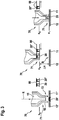
- FIG. 3 is part of the punch riveting device FIG. 2 represented in various positions, with reference to which a sequence of a method according to the invention in a preferred embodiment is to be shown below.
- the setting unit 70 is moved away from the components with the mouthpiece 71, linearly and parallel to a joining direction R and in the direction of one Basic position x 0 , which is set here for the lower end of the mouthpiece 71.
- the storage container 80 with further rivets 20, 20 is spaced from the setting unit 70.
- Reservoir 80 moves to the setting unit 70 and the mouthpiece 71 and that here perpendicular to the joining direction R.
- the rivet 20 is inserted or pressed into the mouthpiece 71.
- a suitable opening may be provided on the mouthpiece 71 or the hold-down 16.
- the introduction of the rivet can be done for example via a blast of compressed air, via a mechanical feed (for example by means of a slider or the like) or via a subsequent pushing of the other rivet elements in a feed rail or a profile hose designed therefor.
- the setting unit 70 can now be brought into the joining position x 1 in the joining direction, in which case the mouthpiece 71 rests against the component 11.
- the joining position x1 can then be introduced by further movement of the punch 15 in the joining direction of the rivet 20 in the components 11, 12.
- a further rivet 20 can be brought to the foremost position in the storage container 80.
- a suitable device conceivable, for example, a spring system, can be provided.
Landscapes
- Engineering & Computer Science (AREA)
- Mechanical Engineering (AREA)
- Insertion Pins And Rivets (AREA)
- Automatic Assembly (AREA)
Applications Claiming Priority (1)
| Application Number | Priority Date | Filing Date | Title |
|---|---|---|---|
| DE102016226244.0A DE102016226244A1 (de) | 2016-12-28 | 2016-12-28 | Verfahren zum Betreiben einer Stanznietvorrichtung, Stanznietvorrichtung und Mundstück für eine Stanznietvorrichtung |
Publications (1)
| Publication Number | Publication Date |
|---|---|
| EP3342504A1 true EP3342504A1 (fr) | 2018-07-04 |
Family
ID=60421700
Family Applications (1)
| Application Number | Title | Priority Date | Filing Date |
|---|---|---|---|
| EP17202963.9A Withdrawn EP3342504A1 (fr) | 2016-12-28 | 2017-11-22 | Procédé de fonctionnement d'un dispositif rivetage, dispositif de rivetage et embout pour dispositif de rivetage |
Country Status (2)
| Country | Link |
|---|---|
| EP (1) | EP3342504A1 (fr) |
| DE (1) | DE102016226244A1 (fr) |
Citations (7)
| Publication number | Priority date | Publication date | Assignee | Title |
|---|---|---|---|---|
| US4609134A (en) * | 1981-06-29 | 1986-09-02 | Gemcor Engineering Corp. | Jet guide rivet injector |
| US5964393A (en) * | 1994-07-04 | 1999-10-12 | Michael Feldpausch | Rivet feed apparatus |
| WO2000007751A1 (fr) * | 1998-08-03 | 2000-02-17 | Henrob Ltd. | Ameliorations concernant les machines de fixation ou se rapportant a celles-ci |
| DE19581624C2 (de) * | 1994-04-14 | 2001-02-01 | Henrob Ltd | Einsetzwerkzeug- und Befestigungselementenbetätigungsanordnung |
| WO2004054738A1 (fr) * | 2002-12-17 | 2004-07-01 | Newfrey Llc | Dispositif d'assemblage orbital |
| EP2318161B1 (fr) | 2008-07-30 | 2014-04-30 | Henrob Limited | Appareil et procédé d'assemblage |
| DE102014224600A1 (de) * | 2014-12-02 | 2016-06-02 | Robert Bosch Gmbh | Stanznietzange mit Stanzniethaltevorrichtung |
Family Cites Families (1)
| Publication number | Priority date | Publication date | Assignee | Title |
|---|---|---|---|---|
| DE102013000388B4 (de) * | 2013-01-11 | 2015-04-23 | Volkswagen Aktiengesellschaft | Setzwerkzeug mit einem magnetisierbaren Setzstempel zum vorlochfreien Fügen von Bauteilen mittels Fügeelement, sowie Fügevorrichtung mit solchem Setzwerkzeug und Verfahren zum Betrieb |
-
2016
- 2016-12-28 DE DE102016226244.0A patent/DE102016226244A1/de active Pending
-
2017
- 2017-11-22 EP EP17202963.9A patent/EP3342504A1/fr not_active Withdrawn
Patent Citations (7)
| Publication number | Priority date | Publication date | Assignee | Title |
|---|---|---|---|---|
| US4609134A (en) * | 1981-06-29 | 1986-09-02 | Gemcor Engineering Corp. | Jet guide rivet injector |
| DE19581624C2 (de) * | 1994-04-14 | 2001-02-01 | Henrob Ltd | Einsetzwerkzeug- und Befestigungselementenbetätigungsanordnung |
| US5964393A (en) * | 1994-07-04 | 1999-10-12 | Michael Feldpausch | Rivet feed apparatus |
| WO2000007751A1 (fr) * | 1998-08-03 | 2000-02-17 | Henrob Ltd. | Ameliorations concernant les machines de fixation ou se rapportant a celles-ci |
| WO2004054738A1 (fr) * | 2002-12-17 | 2004-07-01 | Newfrey Llc | Dispositif d'assemblage orbital |
| EP2318161B1 (fr) | 2008-07-30 | 2014-04-30 | Henrob Limited | Appareil et procédé d'assemblage |
| DE102014224600A1 (de) * | 2014-12-02 | 2016-06-02 | Robert Bosch Gmbh | Stanznietzange mit Stanzniethaltevorrichtung |
Also Published As
| Publication number | Publication date |
|---|---|
| DE102016226244A1 (de) | 2018-06-28 |
Similar Documents
| Publication | Publication Date | Title |
|---|---|---|
| DE102017203943A1 (de) | Setzeinheit und Verfahren zum Setzen eines Verbindungselements an einem Werkstück | |
| DE102017209118A1 (de) | Stanznietvorrichtung zum setzen eines stanzniets mit einer eine stempelkraft unterstützenden schwingung, und verfahren zum stanznieten mit einer solchen stanznietvorrichtung | |
| EP3284548A1 (fr) | Procédé et appareil de pose d'un élément de fixation | |
| WO2019053177A1 (fr) | Dispositif ainsi que procédé pour poser un élément de liaison sur une pièce | |
| DE102015214014A1 (de) | Stanznietvorrichtung und Fertigungsvorrichtung | |
| EP3381581B1 (fr) | Dispositif de poinçonnage et procédé de fonctionnement d'un dispositif de poinçonnage | |
| EP3281721B1 (fr) | Procédé de fixation d'au moins deux composants au moyen d'un dispositif de rivetage auto-poinconnant et dispositif de fabrication | |
| EP3552729A1 (fr) | Dispositif d'installation de rivets auto-poinçonneurs | |
| DE60212359T2 (de) | Stanznietsetzmaschine | |
| WO2004054738A1 (fr) | Dispositif d'assemblage orbital | |
| DE102016226246A1 (de) | Verfahren zum Betreiben einer Fügevorrichtung, Fügevorrichtung und Anordnung mit Fügevorrichtung | |
| EP3552731B1 (fr) | Unité de pose pour un dispositif rivet auto-poinçonneur et dispositif rivet auto-poinçonneur | |
| EP3342504A1 (fr) | Procédé de fonctionnement d'un dispositif rivetage, dispositif de rivetage et embout pour dispositif de rivetage | |
| DE102018222841A1 (de) | Setzeinheit für eine Stanznietvorrichtung, Stanznietvorrichtung und Verfahren zum Verbinden von Bauteilen | |
| DE102018205621A1 (de) | Stanznietvorrichtung mit Zuführeinheit für Niete | |
| DE102015213438A1 (de) | Stanznietvorrichtung und Fertigungsvorrichtung | |
| DE10332124A1 (de) | Vorrichtung zum Verbinden von plattenförmigen Bauteilen mit variabler Fügetechnik | |
| DE102017205659A1 (de) | Stanznietvorrichtung zum setzen eines stanzniets mit einer eine stempelkraft unterstützenden schwingung und verfahren zum stanznieten mit einer solchen stanznietvorrichtung | |
| DE102017208676A1 (de) | Verfahren zum Einbringen eines Lötdepots, Bauteil mit Lötdepot und Fügevorrichtung zum Einbringen eines Lötdepots | |
| CH687366A5 (de) | Vorrichtung zum Ausstanzen eines Fuegeteils und zum Verschweissen desselben mit einem Werkstueck, sowie Sonotrode fuer den Gebrauch in einer solchen Vorrichtung. | |
| DE102019109700B4 (de) | Presse zur Aufnahme einer Werkzeugeinheit und Verfahren zum betriebsbereiten Anordnen der Werkzeugeinheit in der Aufnahme der Presse | |
| EP3342505A2 (fr) | Dispositif et procédé de pose de rivets auto-poinçonnants avec vibration assistant la force du poinçon | |
| DE102017213233A1 (de) | Stanznietvorrichtung und Verfahren zum Verbinden von Bauteilen | |
| DE102006053223B3 (de) | Loch- und Durchzugsstempel | |
| EP3546084A1 (fr) | Procédé de liaison d'au moins deux composants au moyen d'un dispositif de rivetage et dispositif de rivetage |
Legal Events
| Date | Code | Title | Description |
|---|---|---|---|
| PUAI | Public reference made under article 153(3) epc to a published international application that has entered the european phase |
Free format text: ORIGINAL CODE: 0009012 |
|
| STAA | Information on the status of an ep patent application or granted ep patent |
Free format text: STATUS: THE APPLICATION HAS BEEN PUBLISHED |
|
| AK | Designated contracting states |
Kind code of ref document: A1 Designated state(s): AL AT BE BG CH CY CZ DE DK EE ES FI FR GB GR HR HU IE IS IT LI LT LU LV MC MK MT NL NO PL PT RO RS SE SI SK SM TR |
|
| AX | Request for extension of the european patent |
Extension state: BA ME |
|
| STAA | Information on the status of an ep patent application or granted ep patent |
Free format text: STATUS: REQUEST FOR EXAMINATION WAS MADE |
|
| 17P | Request for examination filed |
Effective date: 20190104 |
|
| RBV | Designated contracting states (corrected) |
Designated state(s): AL AT BE BG CH CY CZ DE DK EE ES FI FR GB GR HR HU IE IS IT LI LT LU LV MC MK MT NL NO PL PT RO RS SE SI SK SM TR |
|
| STAA | Information on the status of an ep patent application or granted ep patent |
Free format text: STATUS: THE APPLICATION IS DEEMED TO BE WITHDRAWN |
|
| 18D | Application deemed to be withdrawn |
Effective date: 20190105 |