EP3342629B1 - Technique de connexion variable d'un système d'accumulation d'énergie de traction - Google Patents
Technique de connexion variable d'un système d'accumulation d'énergie de traction Download PDFInfo
- Publication number
- EP3342629B1 EP3342629B1 EP17202948.0A EP17202948A EP3342629B1 EP 3342629 B1 EP3342629 B1 EP 3342629B1 EP 17202948 A EP17202948 A EP 17202948A EP 3342629 B1 EP3342629 B1 EP 3342629B1
- Authority
- EP
- European Patent Office
- Prior art keywords
- energy storage
- energy
- voltage
- vehicle
- cluster
- Prior art date
- Legal status (The legal status is an assumption and is not a legal conclusion. Google has not performed a legal analysis and makes no representation as to the accuracy of the status listed.)
- Active
Links
Images




Classifications
-
- B—PERFORMING OPERATIONS; TRANSPORTING
- B60—VEHICLES IN GENERAL
- B60L—PROPULSION OF ELECTRICALLY-PROPELLED VEHICLES; SUPPLYING ELECTRIC POWER FOR AUXILIARY EQUIPMENT OF ELECTRICALLY-PROPELLED VEHICLES; ELECTRODYNAMIC BRAKE SYSTEMS FOR VEHICLES IN GENERAL; MAGNETIC SUSPENSION OR LEVITATION FOR VEHICLES; MONITORING OPERATING VARIABLES OF ELECTRICALLY-PROPELLED VEHICLES; ELECTRIC SAFETY DEVICES FOR ELECTRICALLY-PROPELLED VEHICLES
- B60L58/00—Methods or circuit arrangements for monitoring or controlling batteries or fuel cells, specially adapted for electric vehicles
- B60L58/10—Methods or circuit arrangements for monitoring or controlling batteries or fuel cells, specially adapted for electric vehicles for monitoring or controlling batteries
- B60L58/18—Methods or circuit arrangements for monitoring or controlling batteries or fuel cells, specially adapted for electric vehicles for monitoring or controlling batteries of two or more battery modules
-
- Y—GENERAL TAGGING OF NEW TECHNOLOGICAL DEVELOPMENTS; GENERAL TAGGING OF CROSS-SECTIONAL TECHNOLOGIES SPANNING OVER SEVERAL SECTIONS OF THE IPC; TECHNICAL SUBJECTS COVERED BY FORMER USPC CROSS-REFERENCE ART COLLECTIONS [XRACs] AND DIGESTS
- Y02—TECHNOLOGIES OR APPLICATIONS FOR MITIGATION OR ADAPTATION AGAINST CLIMATE CHANGE
- Y02T—CLIMATE CHANGE MITIGATION TECHNOLOGIES RELATED TO TRANSPORTATION
- Y02T10/00—Road transport of goods or passengers
- Y02T10/60—Other road transportation technologies with climate change mitigation effect
- Y02T10/70—Energy storage systems for electromobility, e.g. batteries
Definitions
- the invention relates to a traction energy storage system for a vehicle, for example for a commercial vehicle.
- a technique for variable connection, for example for switching on, of energy stores in a traction energy storage system is described.
- the at least partial electrification of a vehicle's powertrain is cost-intensive.
- the development and testing of the energy storage system contribute significantly to the costs. Due to the number of different applications and the associated development and testing effort, the costs multiply.
- On the one hand there is often a desire to electrify as large a number of vehicle derivatives as possible.
- there is a regular need for different degrees of electrification for each vehicle derivative for example a battery electric vehicle (BEV), a plug-in hybrid vehicle (PHEV) and a hybrid electric vehicle (HEV).
- BEV battery electric vehicle
- PHEV plug-in hybrid vehicle
- HEV hybrid electric vehicle
- the document DE 10 2010 002 939 A1 describes a conventional energy storage device.
- the energy store comprises a multiplicity of individual storage cells, with groups of storage cells each being connected to form a storage module and the storage modules being connected up to form the energy store.
- the document U.S. 2007/0080662 A1 describes a further conventional energy store which, in addition to the power interconnection, has a data bus.
- the data bus connects module controls on the individual cell modules with a controller for the energy store.
- the document DE 10 2007 038 532 A1 describes an energy store known as a battery pack with a number of interconnected cells, each of which provides a voltage.
- a monitoring circuit is assigned to one or more cells.
- a coupling arrangement provides a status signal that is galvanically isolated from the cells based on the monitoring circuits.
- the document DE 10 2010 061 025 describes a device for parallel connection of at least two energy units, each having a first energy store, to form an energy unit network in a motor vehicle with at least one electrical consumer unit, the voltage value of each energy unit being able to be determined by a measuring device.
- the contactors used have a certain service life in terms of their switching capability under load. In order to achieve the usual service life in the automotive sector without replacement, the contactors may only be switched up to a component-specific current limit.
- a further or alternative object of the invention is to provide a traction energy storage system for the adaptive storage and release of traction energy, which enables a uniform use of many cells.
- a traction energy storage system for a vehicle comprises a plurality of electrical energy stores, each of the energy stores comprising cell modules electrically connected via busbars, a contactor, an energy store high-voltage interface and an energy store controller controlling the contactor.
- Each of the cell modules includes multiple memory cells and a cell module controller.
- the cell module controllers are designed to output measured values relating to the memory cells in the respective cell module.
- the energy storage controls are designed to determine a storage state depending on the measured values of the cell modules in the respective energy storage.
- the contactor is designed to connect the busbars of the energy storage device to the energy storage high-voltage interface of the respective energy storage device as specified by the energy storage controller when the contactor is in a closed position and to disconnect it when the contactor is in an open position.
- the traction energy storage system includes a connected to the vehicle or Connectable system high-voltage interface that is connected to the energy storage high-voltage interfaces of the energy storage. The energy storage high-voltage interfaces of the energy storage are connected in parallel.
- the traction energy storage system also includes a system controller, which is designed to receive a vehicle instruction to switch on energy storage devices that are currently separate due to the open position, to query the storage states of the energy storage devices that are currently separate, to assign the energy storage devices that are currently separate to one or more clusters on the basis of the queried storage statuses, and to do so Depending on the cluster assignment, switch on the energy storage by closing the contactors using the respective energy storage controls.
- a system controller which is designed to receive a vehicle instruction to switch on energy storage devices that are currently separate due to the open position, to query the storage states of the energy storage devices that are currently separate, to assign the energy storage devices that are currently separate to one or more clusters on the basis of the queried storage statuses, and to do so Depending on the cluster assignment, switch on the energy storage by closing the contactors using the respective energy storage controls.
- An energy storage device can be said to be "disconnected" when its contactor is in the open position.
- Each of the storage states indicates an open circuit voltage of the respective energy store. At least the energy stores that are currently separate are assigned to the clusters depending on their respective open-circuit voltage, preferably by the system controller.
- the energy stores assigned to one of the clusters are switched on when the voltage of the system high-voltage interface matches a range defined by the no-load voltages of the energy stores in the cluster.
- Each of the storage states can also indicate an internal resistance of the respective energy storage device.
- the system controller can also be designed to calculate a compensating current to be expected when switching on, at least for the energy stores that are currently disconnected, on the basis of the respective storage state and a voltage of the system high-voltage interface.
- Each of the storage states can also specify a maximum current (also: current limit) of the respective energy store.
- the energy storage devices that are currently separate can be switched on according to the cluster assignment if the calculated equalizing current is less than the maximum current.
- the maximum current can determine a maximum variance or maximum deviation of the open circuit voltages of the energy storage devices that are assigned to the same cluster.
- the system controller of the traction energy storage system can be designed to only connect energy storage devices in parallel with one another whose difference in open-circuit voltage is less than a specific limit value.
- the system control can determine a maximum deviation of the no-load voltage of the energy storage device to be connected from the voltage of the system high-voltage interface (also: system voltage) of the traction energy storage system. Switching on can take place if (e.g. as soon as) a measured deviation is less than the maximum deviation.
- the system controller can be designed to switch on the energy store of a first cluster (e.g. when the vehicle is started up), with an intermediate circuit store being precharged by means of a first energy store of the first cluster.
- the first energy store of the first cluster can be switched on after the intermediate circuit store has been precharged. All other energy stores of the first cluster can be switched on without pre-charging.
- the energy stores of a cluster (for example the first cluster or a later connected cluster) can be connected one after the other.
- the traction energy storage system can be used both as a range supplement and as a performance supplement, operation can be started by connecting a real subset of the energy stores (e.g. the first cluster), for example to meet a vehicle-side performance requirement.
- the energy stores to extend the range of the vehicle are required at the latest when the charge level of the subset that was initially interconnected is exhausted.
- the system controller can also be designed to switch on the energy storage of a second cluster whose calculated equalizing currents are not (e.g. not all) smaller than the maximum currents by sending a controlling system signal to the vehicle for charging or discharging the traction energy storage system to a setpoint of the system voltage is output.
- the target value e.g. up to the maximum deviation
- the energy store of the second cluster can be switched on.
- the system controller can calculate the setpoint based on the open circuit voltages of the second cluster.
- the system controller can be designed to select as the second cluster the cluster whose no-load voltages have the smallest difference to the voltage of the system high-voltage interface.
- the system controller can be designed to repeat the connection according to the cluster assignment until all energy stores are connected.
- the system controller can also be designed to output a system signal to the vehicle after connection to confirm the connection and/or to indicate a changed connection status.
- the detection of the cell states can include measuring the cell states (e.g. by the respective memory cells), determining the cell states (e.g. by calculation using the cell module controller) and/or obtaining the cell states (e.g. at the cell module controller).
- the functionality of the cell module controller can be integrated in the corresponding energy store controller.
- Each cell module controller can be designed to forward the detected cell statuses in the module status or to determine the module status on the basis of a minimum of the detected cell statuses.
- each energy storage controller can be designed to forward the detected cell states in the storage state or to determine the storage state on the basis of a minimum of the cell states or a minimum of the at least one module state.
- the energy storage controls can each determine the minimum of the cell states in relation to the respective energy storage.
- the system controller can also be designed to determine a discrepancy between the memory states. Depending on the deviation, the cluster assignment can be determined or repeated. The deviation can include a variance in the memory states and/or a difference between the minimum and maximum of the memory states, for example within one or all of the previously determined clusters. The cluster assignment may be updated in response to the deviation exceeding a threshold.
- the memory states can be determined on request from the system controller.
- Each energy storage controller can also be designed to query the at least one module status at the request of the system controller.
- At least one of the cell states, the module states, the memory states and/or the system state can have an open circuit voltage (also referred to as “open-circuit voltage” or OCV) and/or a state of charge (also referred to as “state of charge” or SoC) of the respective Specify cell, the respective module, the respective energy storage and / or the traction energy storage system.
- OCV open-circuit voltage
- SoC state of charge
- Each energy storage controller can determine a cell state of charge of each storage cell (for example by comparison with a stored curve or tabulated relation between open circuit voltage and state of charge) on the basis of the respective cell states (eg cell voltages).
- each cell module controller can determine the cell charge states of its storage cells and output them as cell states. From these cell states of charge, z. B. by averaging, a storage state of charge of the respective energy storage can be determined (as the storage state).
- Each energy storage controller can be designed to output to the system controller a minimum and/or a maximum of the cell voltages of the storage cells in the respective energy storage device and the storage device charge state.
- the system controller can also be configured to receive vehicle instructions from the vehicle.
- a power-on instruction can cause an operational state.
- a shutdown instruction can cause a sleep state.
- the vehicle may be a land vehicle, a watercraft (such as a ship or submarine), or an aircraft.
- the vehicle can be a commercial vehicle (e.g. a truck for goods transport and/or a bus for passenger transport) or a passenger car.
- the cell modules can be electrically connected in each energy store via busbars.
- Each energy store can include at least one contactor.
- the energy storage controller can control the contactor or contactors.
- the contactor or the contactors can be designed to place the busbars of the energy storage device in a closed position with an energy storage high-voltage interface of the respective energy storage device as specified by the energy storage device control of the contactor to connect and to disconnect in an open position of the contactor.
- two contactors can each connect and disconnect one pole of the busbars with the energy storage high-voltage interface.
- the energy storage high-voltage interfaces (individual energy storage or in groups of energy storage connected in series) can be connected in parallel in the traction energy storage system.
- the system controller can be designed to cause the contactors of a controllable subset of the energy storage devices to be in the closed position for the operating state of the traction energy storage system and/or to cause the contactors of all energy storage devices to be in the open position when the traction energy storage system is at rest.
- the energy stores can each be designed for internal charge exchange between the cell modules of the respective energy store, for example via the busbars and/or controlled by the energy store controllers and cell module controllers.
- the cell modules within each energy store can be connected in series or in parallel.
- the contactor can be designed to connect the energy store high-voltage interface of the energy store to the interconnected cell modules in the closed position and to separate it from them in the open position.
- the busbars of each energy store can each include a negative rail and a positive rail with a higher potential than the negative rail.
- the energy storage high-voltage interfaces can each include a negative pole and a positive pole. In the closed position, the busbars can be connected to the energy storage high-voltage interface, in that the positive rail and the negative rail are connected to the positive pole and the negative pole, respectively. In the open position, the busbars can be separated from the energy storage high-voltage interface in that the positive rail is separated from the positive pole, for example when the negative rail is connected to the negative pole.
- the parallel-connected energy storage high-voltage interfaces can also be connected to the vehicle for energy exchange.
- a power network (for example a high-voltage distribution unit) of the vehicle can be connected to the parallel-connected energy storage high-voltage interfaces.
- the energy exchange can be limited to the operating state.
- a current flow between the traction energy storage system and the vehicle (for example an inverter of the vehicle) can be interrupted in the idle state.
- the power network (e.g. the high-voltage distribution unit) of the vehicle and/or a system contactor of the traction energy storage system may interrupt current flow in the idle state.
- the system controller may also be configured to receive signals from the energy storage controllers.
- the signals can each indicate the storage state of the respective energy store.
- the system controller can also be designed to bring about the open position of the contactors of individual energy stores for a measurement phase.
- the measurement phase may include one or more time intervals outside of the operating state.
- the respective energy storage controller can detect an open-circuit voltage (e.g. at the no-load busbars).
- the memory states obtained can be based on an open-circuit voltage of the respective energy store measured in the measurement phase.
- the storage state can indicate the state of charge and/or the no-load voltage of the respective energy store.
- the memory state can depend on a time-related relaxation profile of the open-circuit voltage (for example during the measurement phase).
- the storage state can depend on a temperature and/or a current draw integrated over time.
- the system controller or the respective energy storage controller can be designed to regularly (eg periodically) monitor the storage state.
- the system control or the respective energy storage control can also be designed to cause the contactors of the energy storage to be in the open position if one of the monitored storage states is faulty and/or the monitored current through the energy storage high-voltage interface is greater than the maximum current (also: current limit).
- the system controller can also be designed to receive vehicle instructions (e.g. a data query or a control instruction) from the vehicle. Receipt of a power-on command may initiate the operational state. Receipt of a shutdown command may initiate hibernation. For example, receipt of the switch-off instruction can cause the contactors of all energy stores to be open.
- vehicle instructions e.g. a data query or a control instruction
- the traction energy storage system may further include a system high voltage interface and/or a system contactor.
- the high-voltage system interface is or can be electrically connected to the vehicle, for example to a drive train of the vehicle.
- the system contactor is designed for the energy storage high-voltage interfaces connected in parallel to be connected to the system high-voltage interface as specified by the system controller (in a closed position of the system contactor) and to be disconnected (in an open position of the system contactor).
- the system controller can bring about the closed position of the system contactor in the operating state and/or the open position of the system contactor in the idle state.
- Each of the cell module controllers can be designed to output measured values relating to the memory cells in the respective cell module.
- Each of the energy store controls can be designed to receive the measured values from the cell modules in the respective energy store and to generate a signal depending on the measured values received.
- the system controller may be configured to receive the signals from the energy storage controllers.
- the energy storage control signal can indicate the respective storage state.
- One of the energy storage controllers can perform the function of the system controller. This one energy storage control can also be referred to as a master energy storage control. Each additional energy storage control of the traction energy storage system can also be referred to as a slave energy storage control.
- the system controller function may be implemented in each of the energy storage controllers and enabled for execution in one of the energy storage controllers.
- the system controller function may be enabled for execution in only one of the energy storage controllers. In all other energy storage controls, the function of the system control can be disabled.
- Each of the energy storage controllers may be configured to perform the function in a first energy storage mode and not to perform the function in a second energy storage mode.
- Each of the energy stores can also include a first data interface and a second data interface that is different from the first data interface.
- the data interfaces can each be connected to the energy storage controller within the energy storage device.
- the first data interface outside of the energy store can be unconnected or omitted.
- the second data interface for those energy storage devices to output the signal with the second data interface of the energy store, which performs the function of the system controller.
- the first data interface can be connected to the vehicle outside of the energy storage device in order to output a system signal.
- the second data interface of that energy store can be connected to the second data interfaces of the energy store to receive the signals, which do not perform the function of the system controller.
- the second data interfaces of all energy stores can be connected to a common data bus.
- the system controller can be designed to aggregate the signals received to form the system signal and to output the aggregated system signal, e.g. B. in the operating state of the traction energy storage system.
- the aggregation of the multiple signals into a system signal by the system controller can enable a uniform signal output (or communication) to the vehicle.
- a uniform signal output or communication
- different vehicle derivatives and/or vehicles with different degrees of electrification of the drive train can use a uniform communication interface to the traction energy storage system.
- a structure of the vehicle-side communication interface and a protocol of the vehicle-side communication of the traction energy storage system can be the same for different applications.
- the applications can differ in terms of the number and interconnection of the energy storage devices.
- the number and interconnection of the energy stores can be adapted to an energy and power requirement of the vehicle, for example without adapting the vehicle-side communication.
- the hierarchically structured traction energy storage system with energy storage devices on one hierarchical level and cell modules on a hierarchical level below can enable a charge exchange whose duration does not increase or does not increase linearly with the number of storage cells or cell modules.
- each energy storage controller can be designed to bring about a first charge exchange between the storage cells and/or the cell modules on the basis of the measured values received from the cell module controllers.
- the hierarchical structure can simplify maintenance and/or repair.
- the system signal can be a message contain. The message can be an error message, warning message or diagnostic message.
- the diagnostic message can indicate an individual energy store based on the signals received from the individual energy stores. For example, one of the energy stores can be specified as faulty or aged. Furthermore, the diagnosis report can indicate an individual cell module (for example as faulty or aged) based on cell module-specific measured values. This is advantageous if a usable power of the traction energy storage system depends on the least powerful energy store or cell module. The performance of the traction energy storage system can be restored in a timely and cost-effective manner through a targeted replacement of the specified energy store or cell module.
- the energy storage control of each energy storage can be connected to the respective cell module controls of the same energy storage for data exchange, for example via a serial data bus.
- the measured values can indicate a voltage (e.g. a module voltage of all storage cells) and/or a temperature (e.g. a module temperature, an average temperature or a maximum temperature) of the cell modules.
- Each cell module controller can be designed to record the measured values and/or to output them to the respectively connected energy storage controller.
- the cell module controller can be arranged adjacent to at least one of the respective storage cells. Sensors for recording the measured values can be arranged in the cell module controller.
- Each energy storage controller can be designed to generate the signal on the basis of the measured values obtained from the respective cell modules.
- the energy storage controller can be designed to record further measured values (e.g. the no-load voltage of the energy storage device or a current output by the energy storage device), and on the basis of these to generate the signal (e.g. to indicate the storage state).
- the signals and/or the system signal can indicate a measured value, a status value or a diagnostic value.
- the aggregation of the signals to form the system signal (also: aggregation rule) can include an averaging, a minimum determination and/or a maximum determination.
- the system controller can be designed for bidirectional communication with the vehicle.
- the system controller can be designed to receive a vehicle signal.
- the system controller may analyze the vehicle signal and output a control signal to at least one of the energy storage controllers based on the analysis.
- the vehicle signal may include a control command (e.g., the vehicle command) and/or a status query.
- the system controller can be designed to receive an emergency shutdown signal from the vehicle via the first data interface.
- the system controller may also be configured to send a control signal to disconnect the contactors to the energy storage controllers upon receipt of the emergency shutdown signal.
- the signals can indicate the storage status of the respective energy storage device (which can also be referred to as energy storage status).
- the aggregated system signal may indicate a system state of the traction energy storage system.
- a data format for indicating the status, a physical definition of the data interface used in each case and/or a communication protocol can be consistent for the signals and the aggregated system signal.
- the storage state and the system state can indicate a current state of the respective energy store or the traction energy storage system. Alternatively or additionally, the storage state and the system state can indicate a (eg, predicted) performance of the respective energy store or of the traction energy storage system.
- the signals from the energy storage controls can indicate a current state of charge and/or a maximum current (e.g. that can be drawn in the future) of the respective energy storage.
- the state of charge can be determined from the measured voltage (e.g. the no-load voltage) using a tabulated discharge curve, for example.
- the maximum current (for example for charging and/or discharging) can be determined from the state of charge and/or the measured temperature, for example by means of a tabulated function.
- Each energy storage controller that does not perform the system control function can output its own signal (e.g., with its own data set and/or by means of its own datagram) to the energy storage controller that performs the system control function.
- the energy storage controls can each be designed to determine the storage state of the respective energy storage based on the measured values received from the cell modules and/or the other measured values.
- the energy storage control can also be designed to disconnect the respective contactor or the respective contactors and/or to generate an error message as the signal and to output it to the system controller when an impermissible storage state is detected.
- the signal from the relevant energy storage control can designate the impermissible storage state and/or indicate impermissibility as such.
- Determining the storage state can include measuring the current supplied or consumed by the respective energy store.
- the impermissible memory state can be determined when the maximum current is exceeded (e.g. for charging or discharging).
- the signals can each indicate the maximum current that can be drawn from the respective energy store.
- the aggregated system signal can indicate n times the smallest of the signaled maximum currents that can be drawn off. The factor n can be the number of interconnected energy stores.
- Determining the storage state can include determining the charge state of the respective energy store or a charge that can be drawn from the respective energy store.
- the impermissible storage state can be determined when the charge falls below a minimum.
- the signals generated can each indicate the state of charge or the charge that can be drawn from the respective energy store.
- the system state can indicate the sum of the signaled removable charges.
- the charge that can be drawn can be determined by integrating the current over time. Alternatively or additionally, the charge that can be drawn can be determined on the basis of the measured voltage using a tabulated function.
- Each of the energy stores can be arranged in its own housing. At least one of the following features can be arranged in one or more outer surfaces of the housing: the first data interface, the second data interface and the energy storage high-voltage interface.
- a vehicle for example a commercial vehicle, with such a traction energy storage system and a method for producing a vehicle with the installation of such a traction energy storage system are provided.
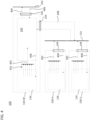
- FIG. 12 shows a schematic block diagram of a traction energy storage system (TES system) for a vehicle, for example a commercial vehicle, which is generally designated by reference number 100 .
- the TES system 100 includes at least two energy stores 110.
- Each energy store 110 includes a plurality of cell modules 120 and an energy store controller 130.
- Each of the cell modules 120 includes a plurality of storage cells 122 and a cell module controller 124.
- Each cell module controller 124 acquires measured values relating to the associated memory cells 122.
- the cell module controller 124 acquires a voltage and/or a temperature of the memory cells 122 in the respective cell module 120.
- Each of the cell module controllers 124 is designed to output the measured values on an internal data bus 126 .
- the internal data bus 126 of the cell module 120 can be a serial bus, for example for a controller area network (CAN).
- Each of the energy storage controllers 130 is designed to receive the measured values from the cell modules 120 in the respective energy storage device 110 .
- each energy storage controller 110 is connected to the respective internal data bus 126 .
- Each of the energy storage controllers 130 is also configured to generate a signal depending on the measured values obtained.
- the energy storage controller 130 is connected to an external data bus 132 in order to output the signal or other signals.
- the external data bus 132 of the TES system 100 can be a serial bus, for example another CAN bus.
- the external data bus 132 can be designed exclusively for communication between the energy stores 110 (or their energy store controls 130).
- the energy stores 110 are each arranged in their own housing 112 .
- the internal data bus 126 runs inside the respective housing 112.
- the external data bus 132 runs outside the housing 112.
- the TES system 100 further includes a system controller 140.
- the system controller 140 may be configured to receive signals from the energy storage controllers 130, generate a system signal based on the received signals, and output the system signal to a functional network 150 of the vehicle.
- the functional network 150 can include a low-voltage vehicle electrical system and/or a bus system for communication between vehicle functions.
- the low-voltage electrical system can provide a supply voltage of 24 volts.
- the external data bus 132 can be designed exclusively for communication between the energy stores 110 (or their energy store controls 130).
- the function network 150 can be connected to the system controller 140 via its own interface and/or its own bus connection 202 . You can do this yourself Bus (for example, a separate CAN bus) can be provided for vehicle communication, which operates independently of the external data bus 132 .
- the external data bus 132 (e.g. instead of the separate bus connection 202 or in addition thereto) can be connected to the functional network 150 (dashed arrow).
- the TES system 100 can include a uniform vehicle interface to the functional network 150 of the vehicle, which is independent of the number of energy stores 110 used and connected to one another.
- the vehicle interface can be on a physical level (e.g. in terms of plug connection and/or signal course) or a bit transmission layer (e.g. in terms of a communication protocol) independently of a variable composition of the energy storage devices 110 included in the TES system 100 be.
- the system controller 140 can be implemented in an energy store 110 , for example in one of the energy store controllers 130 . Alternatively or additionally, the system controller 140 can be implemented outside of the energy store 110, for example as a separate device in a separate housing or as a component of the function network 150.
- An energy store 110, which performs the function of the system controller 140, is also known as a master energy store 110- M denotes.
- the energy store or stores 110 which do not perform the function of the system controller 140 are also referred to as slave energy stores 110-S. Corresponding designations apply to the respective energy storage controls 130-M or 130-S.
- the system controller 140 may be configured to receive the signals from the energy storage controllers 130 -S via the external data bus 132 .
- the system signal can be output from the system controller 140 to the functional network 150 via a direct connection (e.g. the bus 202) of the system controller 140 to the functional network 150 .
- the system signal can be output to the functional network 150 via the external data bus 132 .
- the function network 150 is connected to the external data bus 132 (for example directly or via a gateway).
- the storage cells 122 of a cell module 120 are connected together (for example in series).
- the connection terminals 127 resulting from the interconnection are over Busbars 128 connected.
- the bus bars 128 can be made of aluminum or another conductive material.
- the poles resulting from the combination of the cell modules 120 of each energy store 110 form an energy store high-voltage interface 114 (hereinafter: high-voltage interface).
- the high-voltage interfaces 114 can be connected in parallel or in series and can be connected or can be connected to a power grid 160 of the vehicle.
- the power network 160 can include a high-voltage electrical system of the vehicle.
- a drive train of the vehicle can be connected to the power grid 160 in order to draw off the energy stored in the TES system 100 and/or to charge the TES system 100, for example during a recuperative braking process.
- the drive train can include a crankshaft starter generator or an electric machine as the primary drive (possibly connected via an inverter).
- the power network 160 can also be referred to as a traction network.
- the power grid 160 can provide a voltage of at least 60 volts, for example between 540 volts and 738 volts.
- the power network 160 can be any high-voltage vehicle electrical system within the meaning of vehicle construction.
- a topology of power network 160 and/or its components can delimit power network 160 from a low-voltage network (of, for example, 24 volts, in particular the low-voltage vehicle electrical system).
- the topology can correspond to or be adapted to a known vehicle topology for hybrid, plug-in or electric vehicles.
- the components may include a traction drive converter (e.g., the inverter or inverter), the TES system 100, one or more electric machines, accessories, and/or a wire harness.
- At least one contactor 170 is preferably arranged in each energy store 110 between the cell modules 120 and the power grid 160 .
- the contactor 170 is or the contactors 170 are controlled by the energy storage controller 130 in the same energy storage device 110 via the control line shown with reference number 172 for selectively disconnecting the respective energy storage device 110 from the power grid 160 .
- Contactor 170 may be part of a contactor box that also monitors the electrical isolation of bus bars 128 (e.g., from a reference potential), measures the current flowing through bus bars 128, and/or measures the voltage across bus bars 128 (e.g., at open contactor the no-load voltage).
- the contactors 170 of the connected (and possibly functional) energy stores 110 can be closed (closed position).
- the corresponding energy store 110 can be isolated from the network of the TES system 100 in the operating state of the TES system 100, for example in the event of an impermissible storage state or for measuring the open-circuit voltage.
- the system controller 140 can bring about the open position of the contactors 170 of all energy storage devices 110 when the TES system 100 is in an idle state.
- a pre-charging contactor (or in short: pre-charging contactor) and a pre-charging resistor connected in series with the pre-charging contactor can be installed in each energy store 110 in parallel with one of the contactors 170 (which can also be referred to as main contactors).
- the pre-charging resistor can be a PTC thermistor or PTC resistor.
- the energy storage controller 130 may close the pre-charge contactor. The energy storage controller 130 can bring about the closed position of the contactors 170 as soon as a voltage difference at the pre-charging resistor falls below a threshold value.
- the system controller 140 is also designed for bidirectional communication with the functional network 150 of the vehicle.
- the system signals may be generated and output in response to a vehicle signal (from the vehicle's function network 150).
- the vehicle signal can include a control instruction.
- the system controller 140 analyzes the control instruction to determine those energy stores 110 that are relevant for implementing the control instruction, and outputs a control signal to the energy store controllers 130 of the energy stores 110 in question.
- the TES system 100 can be used in a scalable manner at the energy storage 110 level due to the modular structure.
- the energy stores 110 can be connected multiple times in parallel or in series.
- the TES system 100 can be configured for a vehicle-specific power and energy requirement by interconnection and the number of interconnected energy stores 110 . These requirements may depend on the level of electrification of the vehicle's powertrain. Furthermore, the power requirement can be determined by a transport capacity of the vehicle, for example the commercial vehicle, and the energy requirement can be determined by a range of the vehicle.
- the connection and/or the number of connected energy stores 110 can be changeable in the operating state, for example controllable by the vehicle signal.
- the system controller 140 preferably provides a uniform data interface to the vehicle with regard to a physical interface and a communication protocol, which can be independent of the vehicle-specific configuration of the TES system 100 . Due to the communication via the system controller 140, the plurality of energy stores 110 can behave in relation to the vehicle like a correspondingly large energy store. This minimizes vehicle-specific integration effort.
- figure 2 1 shows a schematic block diagram of a second embodiment of a TES system 100, the features of which are in common with the first embodiment of FIG figure 1 can be combined.
- Reference numerals that correspond to the other exemplary embodiments designate corresponding or identical features.
- the system controller 140 is arranged outside of the housing 112 of the energy store 110 .
- the system controller 140 includes a first data interface 142 for vehicle-side communication.
- the first data interface 142 is connected to the functional network 150 and/or an engine controller.
- the system controller 140 includes a second data interface 143 which is connected to data interfaces 144 of the energy store 110 via the external data bus 132 .
- the system controller 140 receives the signals from the individual energy stores 110 via the second data interface 143.
- the system signal is output via the first data interface 142.
- the high-voltage interfaces 114 of the individual energy stores 110 are connected in parallel and connected to the power grid 160 and/or the inverter.
- a system high-voltage interface 162 can be provided for exchanging energy between the TES system 100 and the vehicle's power grid 160 .
- the current / through the system high voltage interface 162 is referred to as the system current 204 .
- the uniform voltage U of the parallel circuit is present at the system high-voltage interface 162 and is referred to as the system voltage 206 .
- the system current 204 can also be referred to as the total current of the TES system 100 due to the parallel connection.
- a system contactor 164 controlled by the system controller 140 makes it possible to switch the system high-voltage interface 162 free of voltage.
- the system contactor 164 can be arranged in a high-voltage distribution unit of the power grid 160 .
- the system contactor 164 can directly (e.g. via the external data bus 132) or indirectly (for example via a component of the function network 150) by the system controller 140.
- First data interface 142 is connected to a serial bus 202 of vehicle function network 150 , for example a CAN bus that is independent of TES system 100 .
- figure 3 10 shows a schematic block diagram of a third exemplary embodiment of a TES system 100 for a vehicle.
- the third exemplary embodiment differs from the second exemplary embodiment in that the function of the system controller 140 is carried out in an energy store 110 -M of the energy store 110 .
- the energy store 110 -M includes the first data interface 142 .
- the energy store 110 -M receives the signals from the other energy stores 110 - S which do not perform the function of the system controller 140 via a second data interface 144 .
- the first data interface 142 and the second data interface 144 are each connected in the energy store 110 -M to the energy store controller 130 -M, which performs the function of the system controller 140 .
- All energy stores 110-M and 110-S are preferably identical in construction.
- the energy stores 110-S can also include a first data interface 142, which is not connected outside of the energy store 110-S.
- the second data interfaces 144 of all energy stores 110 -M and 110 -S are connected via the external data bus 132 .
- the function of the system controller 140 is also implemented in each energy storage controller 130-S of the energy storage devices 110-S and is not activated for execution (shown as a dashed function block in figure 3 ). By setting one or more energy storage controller 130 parameters, the system controller 140 function may be selectively enabled and disabled for execution.
- the in the figures 2 and 3 The parallel connection of the three high-voltage interfaces 114 shown is an example. Depending on the requirements of the vehicle power network 160 (e.g. in terms of current, voltage, power and/or energy), a larger number of energy stores 110 and/or a different interconnection of the high-voltage interfaces 114 can be used. In particular, the high-voltage interfaces 114 can be connected in series within a group of energy stores 110, and the groups can be connected in parallel with one another.
- figure 4 10 shows a functional block diagram of the TES system 100, the functional features of which are optionally implemented in each of the above exemplary embodiments.
- the functional features may be implemented, at least in part, by an application specific integrated circuit (ASIC) and/or encoded in memory accessed by a processor to execute the functional features.
- ASIC application specific integrated circuit
- the energy storage controller 130 -M which performs the function of the system controller 140 , can be composed of a slave function set 134 and the function set of the system controller 140 .
- the slave functional scope 134 can correspond to the functional scope for the individual operation of a single energy store and/or the operation as a slave energy store 110-S.
- the slave functionality 134 may match the (active) functionality of the other energy storage controllers 130-S.
- the slave functionality 134 may include an existing functionality of a conventional energy store. As a result, the energy store 110 can be downwardly compatible with individual operation.
- the data 401 relating to the memory cells 122 in the energy store 110-M are multiplexed by the energy store controller 130-M into an application format of the system controller 140 and transferred to the system controller 140 at a virtual or physical interface as a signal 402 of the energy store 110-M.
- Corresponding data relating to the memory cells 122 of the other energy storage devices 110-S are multiplexed in the respective energy storage device controls 130-S into the application format of the system controller 140 and as the signal 402 of the energy storage device 110-S at the second data interface 144 of the respective energy storage device 110-S by means of of the external data bus 132 to the system controller 140.
- the system controller 140 outputs the system signal 404 to the first data interface 142 on the basis of the signals 402 from the energy stores 110 .
- the system controller 140 can receive a vehicle signal 406 at the first data interface 142 .
- the system controller 140 processes the vehicle signal 406.
- the system controller 140 selectively forwards the vehicle signal 406 (possibly after signal processing) or transmits a control signal 408 derived from the vehicle signal 406 to the slave functional scope 134 of the respective energy storage controllers 130-M and/or 130-S off.
- each energy storage controller 130 as a master energy storage controller 130-M with an activated function of the system controller 140 or as a slave energy storage system controller 130-S with a deactivated function of the system controller 140 can be achieved in that the function of the system controller 140 implemented in all energy storage controllers 130 in the performs a forwarding function in the disabled state.
- the forwarding function forwards the signals 402 (i.e., the multiplexed data) directly to the second data interface 144 of the respective energy store 110-S for output.
- the control signals 408 received at the second data interface 144 of the respective energy store 110-S are forwarded to the slave functional scope 134 of the energy store controller 130-S.
- an emergency shutdown signal 406 can be received from the vehicle at the first data interface 142 .
- the system controller 140 outputs a control signal 408 to the contactor 170 of its own energy store 110-M and via the external data bus 132 to all other contactors 170 to disconnect (i.e. potential-free) the high-voltage interfaces 114.
- a single communication interface to the vehicle is provided by the first data interface 142 connected to the system controller 140, so that the TES system 100 resembles a single energy storage device with corresponding storage properties in terms of communication with the functional network 150 of the vehicle.
- each individual energy storage device 110 can optionally be configured as an unconnected individual energy storage device, as a master energy storage device 110-M in the network of the TES system 100, or as a slave energy storage device 110-S in the network of the TES system 100 become.
- the system controller 140 uses the system signal 404 to output, for example, an aggregated common state (or status) of all energy stores 110 belonging to the TES system 100 .
- Each signal 402 that is output by one of the slave energy storage controls 130-S is aggregated in the master energy storage control 130-M by the system control 140 with the corresponding signals 402 (if any) of the other energy storage 110 and as a common value as the system signal 404 communicates outwards to the vehicle via the first data interface 142 .
- the aggregation also includes a control function.
- the control function includes checking the connection status of all energy stores 110 on the external Data bus 132.
- the control function includes a plausibility check of the signals received from the slave energy storage controls 130-S. The plausibility check compares the received signal with limit values (eg current limits) stored for the signal type in the system controller 140 for the respective energy store 110-S.
- limit values eg current limits
- the system controller 140 If a received signal is faulty, implausible or not present, the system controller 140 carries out an error response.
- the system controller 140 calculates the aggregated electrotechnical variable depending on the interconnection of the high-voltage interfaces 114 and outputs it as the system signal.
- the wiring used for the high-voltage interfaces 114 is stored in the system controller 140 in the course of the configuration of the master energy store 110 -S.
- aggregation rules are stored in the system controller 140 depending on the interconnection. The aggregation rules can define the aggregation of the storage states of the connected energy stores 110 to the TES system state.
- the signals 402 of the individual energy stores 110 which indicate a measured temperature, are aggregated by finding an extreme value among the signaled temperature values. For example, among all the signaled temperature values that are greater than 0° C., the largest temperature value in the system signal 404 is output. As an alternative or in addition, the lowest temperature value in the system signal 404 is output from among all signaled temperature values that are less than or equal to 0°C.
- the individual energy stores 110 are preferably kept in an operating temperature range by common coolant circulation. Among the coolant temperature values signaled by the individual energy stores 110, the highest temperature value is output as the system signal.
- the signals 402 received from the individual energy stores 110 optionally indicate a charge (eg absolute in coulombs or relative, for example a remaining residual charge).
- a charge eg absolute in coulombs or relative, for example a remaining residual charge.
- the sum of the signaled charges is output in system signal 404.
- the signals 402 indicate a maximum current for each available energy store 110 .
- the smallest maximum current (from the signaled maximum currents of the individual energy stores 110) is multiplied by the number of available energy stores 110 and output in the system signal 404.
- An energy store 110 is available if it has no error message and no error has been detected by the system controller 140 .
- each individual energy store 110 is operated within the limits that are continuously checked for its intrinsic safety. Furthermore, by excluding faulty energy stores 110 due to the parallel connection of the high-voltage interfaces 114 with only some of the energy stores 110 (eg the first cluster), the vehicle can be operated. As a result, redundant operation (eg in the event of an overcapacity of energy stores 110) or emergency operation (eg a so-called “limp home mode”) can be implemented.
- Faulty energy stores 110 are separated from the power grid 160 by means of the respective contactor 170 or the respective contactors 170 .
- Each individual energy store 110 implements its intrinsic safety. As a result, the system controller 140 may not be relevant to security.
- the signals 402 of the individual energy stores 110 optionally indicate an energy content of the respective energy store 110 .
- the system signal 404 indicates a total extractable energy content.
- the system signal 404 can be based on an (optionally weighted) sum of the individual energy contents.
- the contribution of the individual energy content of each energy store 110 to the total energy content that can be drawn off can be determined from a proportionate battery current.
- the total resistance can be calculated according to the interconnection of the high-voltage interfaces 114 and output as a system signal 404 .
- the system controller 140 determines the proportionate battery current on the basis of the signaled internal resistance values.
- the system controller 140 receives signals 402 from each energy store 110 with service life-optimized limit values (for an upper limit and a lower limit) of the state of charge. For the aggregation of the service life-optimized limit values of the state of charge, the system controller 140 selects the service life-optimal limit values of the state of charge, which are as close as possible to the current distribution of all energy stores 110 resulting therefrom optimally traced back to a target aging curve. The resultant current distribution of the individual energy stores 110 is calculated by the system controller 140 from the internal resistance values signaled by the individual energy stores 110 .
- the individual energy stores 110 can also indicate an aging state (also referred to as “State of Health” or SoH) of the respective energy store 110 .
- the aging status of the individual energy storage devices 110 is used by the system controller 140 as an error indicator for the respective energy storage device 110 (e.g. when limit values are exceeded) and/or to calculate a service life-optimized limit value for the current of the respective energy storage device 110 or the TES system 100 used.
- the storage state (e.g. the state of charge and/or the aging state) can be calculated according to the same aggregation rules that are also implemented for the state aggregation of the individual storage cells 122 within the cell module controller 124 .
- the signals 402 of the individual energy stores 110 indicate a voltage value (for example a current and/or a predicted voltage value) for the individual energy stores 110 .
- the system signal 404 for the corresponding voltage value is calculated by the system controller 140 according to the interconnection of the high-voltage interfaces 114 .
- a system state 404 of the TES system 100 can be determined by selecting the safest or most conservative state from among the states 402 signaled as available by the energy stores 110 .
- the TES system 100 can be operated according to the lowest-performing energy storage system 110 .
- the safest state can be the most reliable state for the current operation of all energy stores 110 .
- the most conservative state can maximize a lifetime of all energy storage devices 110 .
- all vehicle signals 406 which the master energy store controller 110 -M receives from the vehicle are distributed to the respective slave functional scope 134 of the individual energy store controllers 130 . If necessary, the vehicle signal is converted into a control signal 408 that is specific to each individual energy storage controller 130 .
- the aggregation and distribution of the signals by the system controller 140 also affects diagnostics of the TES system 100 (e.g., diagnostic requests from the vehicle to the system controller 140 and diagnostic messages from the system controller 140 to the vehicle). Diagnostic messages from the individual energy storage controls 130 are collected by the system controller 140 and output in aggregated form to the vehicle via the first data interface 142 .
- the aggregation can include the formation of a uniform data set in a data packet of the system signal 404, for example. Diagnosis values relating to the individual cell modules 120 are listed in the data set without being grouped in the energy store 110 .
- Diagnostic queries (which are also referred to as diagnostic routines) from the vehicle are received at the first data interface 142 of the system controller 140 and forwarded to the existing range of functions 134 of the individual energy storage controllers 130 .
- each energy store 110 can include electrochemical state variables (for example state of charge, aging state or storage capacity) and/or electrotechnical variables (for example current, open circuit voltage, internal resistance).
- each energy store 110 can describe its storage capability as the charge that can be drawn in the fully charged state (eg the time integral of the discharge current from the initial voltage to the final voltage).
- the state of charge (also referred to as “state of charge” or SoC) of each energy store 110 is the portion of the charge that can still be drawn from the storage capacity.
- the functional relationship between the (eg relaxed) open circuit voltage (OCV) at the high-voltage interface 114 and the state of charge of the energy store 110 is the discharge curve.
- the storage state of each energy store 110 includes at least one of the following variables of the respective energy store 110: the storage capacity, the state of charge, an aging state, the open circuit voltage, an internal resistance, a first time constant (e.g. caused by an electrochemical double layer between electrode and electrolyte) and/or a second time constant (e.g. caused by diffusion of the ions in the electrolyte).
- the first time constant can be a fraction of a second, for example less than 0.1 s or 0.01 s.
- the second time constant can be greater than the first time constant, for example greater than 1 s or 10 s.
- the instantaneous state of charge can be determined on the basis of the measured no-load voltage.
- the discharge curve can be tabulated and/or updated by integrating the current in the operating state.
- the individual energy stores 110 in the TES system 100 can differ in their discharge curves and/or storage states, for example in terms of storage capacity, state of charge, open circuit voltage, internal resistance, first time constant and/or second time constant.
- the cause and local influencing factors of the deviating storage states of the individual energy storage devices 110 are, for example, production variability, aging and temperature.
- the energy stores 110 are therefore in different storage states (for example in or after an operating state of the TES system 100 when the vehicle is switched off and/or a terminal of the vehicle ignition is at a reference potential).
- the state of charge and/or no-load voltage of the individual energy stores 110 can be non-uniform.
- Such deviating storage states can arise in the operating state due to different internal resistances or time constants, even if the storage capacities and discharge curves are essentially the same.
- relaxation effects e.g. with different second time constants
- self-discharge e.g. with different discharge rates
- each energy store 110 monitors the operating limits of its cell modules 120 and/or its storage cells 122.
- the current limit of the cells 122 and thus the current limit of the energy store 110, depend on the operating conditions (e.g. temperature, current, time and/or SoC) off.
- the current limit may be near zero at a cell 122 temperature of -30°C.
- the switch-on function for parallel-connectable energy storage devices 110 must meet these requirements in order to have a functioning TES system 100 make possible.
- a symmetrical subset of the energy stores 110 and further asymmetrical energy stores 110 can be distinguished on the basis of the storage state (for example the no-load voltage) of the energy stores 110 .
- “Balanced” energy storage devices 110 have similar storage states, preferably similar open circuit voltages (as a storage state or as part of the storage state). The compensating currents resulting from the difference in the no-load voltages do not violate the current limits of the interconnected energy stores 110 when symmetrical energy stores 110 are interconnected Energy storage 110 are added (for example, during operation of the vehicle).
- a Function for adapting also: balancing function, for example with regard to OCV or SoC
- balancing function for example with regard to OCV or SoC
- FIG. 14 shows one embodiment of the staging function 500 in the shuntable TES system 100.
- the staging function 500 is preferably implemented in the system controller 140.
- FIG. 5 14 shows one embodiment of the staging function 500 in the shuntable TES system 100.
- the staging function 500 is preferably implemented in the system controller 140.
- FIG. 5 14 shows one embodiment of the staging function 500 in the shuntable TES system 100.
- the staging function 500 is preferably implemented in the system controller 140.
- the master energy store 110-M (in particular the system controller 140) receives a connection request from the vehicle function network 150, the master energy store 110-M (in particular the system controller 140) activates the slave energy store 110-S (in particular the respective functional scope 134) by a corresponding instruction 502 in signal 408.
- instruction 502 sets slave energy store 110-S from an energy-saving mode with functionality 134 into an active mode with functionality 134.
- the storage state of the j -th energy store 110 includes the internal resistance 504- j (symbolic: R j ) and/or the open circuit voltage 506- j (symbolic: OCV j ).
- the term "memory state" may be defined to also include current boundaries 508- j .
- the system controller 140 of the master energy store 110-M calculates the equalizing currents 512 to be expected between the energy stores 110 that are then interconnected if the connection is changed (in particular when a further energy store 110 is connected).
- all symmetrical energy stores 110 are combined in cluster 1 .
- Energy stores 110 that are similar in terms of their storage state and are asymmetrical with respect to cluster 1 are combined in clusters 2 to m .
- connection capability of the clusters, or individual energy stores 110 in the clusters is determined by comparing the calculated equalizing currents 512 with the respective current limits 508- j .
- the vehicle can start z. B. start with full power, but possibly not yet with full range.
- the first cluster e.g., "symmetric" cluster by definition
- the cluster with the highest (e.g., cluster-averaged) memory state e.g. B. with the highest open circuit voltage or the highest state of charge.
- the first energy store 110 is switched on by closing its contactor 170 .
- connection status is output as feedback in signal 404 to vehicle function network 150 .
- the connection status may indicate the proportion connected to the vehicle power grid 160 (e.g., related to the number of energy storage devices 110 or storage capacity) (e.g., "50% of the energy storage devices connected").
- the system controller 140 issues a request in signal 404 to the vehicle function network 150 to move to a specific state.
- the determined state can be output in signal 404 as a target value for the system state.
- a specific voltage level e.g. a target voltage for the system voltage 206
- a specific system state of charge e.g. a target value for the aggregated SoC
- the connected energy stores 110 are specifically brought to a storage state over time that corresponds to the specified value of the system state.
- the No-load voltage of the connected energy stores 110 brought to the specific voltage level by charging or discharging the TES system 100.
- step 524 the system controller 140 monitors the approach of the storage states (of the energy storage devices 110 already connected) or for the (already connected clusters 1, ..., k -1) aggregated states to the determined state (e.g. the open circuit voltage).
- the determined state e.g. the open circuit voltage
- step 526 the system controller 140 sequentially instructs all energy stores 110 of the kth cluster to switch on. A further subpoena is no longer required.
- An updated connection status is output as feedback to the vehicle (e.g. "80% of the energy storage devices connected”).
- Steps 522 to 526 can be repeated until all energy stores 110 are connected.
- the cluster with the highest or lowest memory state e.g. OCV and/or SoC
- the cluster with the highest voltage level can be selected for optimal charging.
- the cluster with the highest voltage level can be selected during discharging for maximum power.
- FIG. 6 schematically shows an example of a time profile 600 of the system voltage 206 or a system open-circuit voltage.
- a cluster 1 ie a symmetrical subset of the energy stores 110
- the high-voltage interface 162 to which the system voltage 206 is present.
- the TES system 100 includes at least one other energy store 110, which is or are assigned to either a cluster 2 or a cluster 3.
- the energy stores 110 of each cluster (for example clusters 2 and 3) can each be symmetrical to one another, for example so that the connection capability only has to be determined once for each cluster connection.
- the energy stores 110 of each cluster are related to another cluster (e.g. the one currently with the high-voltage interface 162 connected clusters 1) asymmetrical.
- the system controller 140 instructs the vehicle to increase the system voltage 206 or the open-circuit voltage of the TES system 100 (ie the open-circuit voltage of the group of energy storage devices 110 that are currently connected together), the open-circuit voltage 602-2 of cluster 2 approach as an example of the state to be approached.
- the system voltage 206 or the system no-load voltage changes depending on the operating state (charging or discharging) according to the curve 600.
- a region 604- k is defined around the open circuit voltage 602-k of the kth cluster. If in step 524 the system voltage 206 or the system no-load voltage reaches the range 604- k (connection capability), the energy stores 110 of the k th cluster are connected in step 526, for example one energy store 110 of the k th cluster after the other.
- a separate range around the no-load voltage of the respective energy store 110 can be defined for each energy store 110 to be switched on.
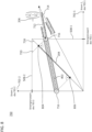
- figure 7 schematically shows a diagram 700 of the currents in the TES system 100.
- the system controller 140 receives from each energy store 110 at least one current limit 508- j for the respective partial flow 702- j of the j -th energy store 110, e.g. B. a maximum current for each of the operating state of charging and the operating state of charging discharging.
- the current limits of the energy storage devices 110 are met in that the voltage drop U at the vehicle (for example at the DC voltage input of the inverter) is so great that the state 716 of the current distribution 710 at the edge or within the rectangle determined by the current limits 508-j (generally: n -dimensional rectangle) lies.
- the inside figure 7 State 716 shown is on the edge of the permissible range, which is determined by limit value 508 - 1 of first energy store 110 .
- the state 716 shown corresponds to a minimum system voltage U , ie the smallest permissible system voltage 206 for the parameters 712 and 714 (calculated, for example, from the memory states 504 and 506 obtained).
- the portion of the vector of the current distribution 710 in the plane 720 that is perpendicular to the bisecting line 718 corresponds to the equalizing currents 512 within the TES system 100.
- figure 8 shows schematically in diagram 700 the states 716 that are permissible during operation and possible for the parameters 712 and 714 (calculated, for example, from the memory states 504 and 506 obtained) on a line 802. Larger system voltages 206 than in figure 7 State 716 shown correspond to smaller system currents 204 having a current distribution vector 710 whose endpoint (ie, state 716) is within the rectangle defined by current limits 508 (according to Equation 2) on line 802 extending reciprocal internal resistance vector 712.
- the system upper limit, I max , for the system current 204 is in figure 8 shown at reference numeral 804.
- the (in the diagram 700 in figure 8 lying on the left edge) State 716 of the smallest system current 204 corresponds to the largest permissible system voltage 206.
- the aggregated current limits 804 and 806 of the energy stores 110 already connected can be determined according to figure 8 , whose aggregate internal resistance (as the reciprocal of the sum of the reciprocal internal resistances R j ) and whose aggregate open-circuit voltage (for example the mean of the open-circuit voltages OCV j weighted with the reciprocal internal resistances R j ) are determined.
- the connection capability can be determined in step 524 by using the aggregated internal resistance or the aggregated no-load voltage in equation (1) for R 1 and OCV 1 , and the internal resistance or the no-load voltage of the energy store 110 to be switched on for R 2 and OCV 2 .
- step 510 and/or 524 based on the storage states 504- j and 506- j , the current distribution 710 of the energy stores 110 can be calculated, which would result after connection.
- These partial currents 702- j of the current distribution 710 are compared (as compensating currents 512) in step 514 or 524 with the respective current limits 508- j .
Landscapes
- Engineering & Computer Science (AREA)
- Life Sciences & Earth Sciences (AREA)
- Sustainable Development (AREA)
- Sustainable Energy (AREA)
- Power Engineering (AREA)
- Transportation (AREA)
- Mechanical Engineering (AREA)
- Electric Propulsion And Braking For Vehicles (AREA)
- Charge And Discharge Circuits For Batteries Or The Like (AREA)
Claims (14)
- Système d'accumulation d'énergie de traction (100) pour un véhicule, comprenant :plusieurs accumulateurs d'énergie (110) électriques, chacun des accumulateurs d'énergie comportant des modules de cellules (120) reliés électriquement par le biais de barres bus (128), un contacteur de commutation (170), une interface à haute tension d'accumulateur d'énergie (114) et une commande d'accumulateur d'énergie (130) qui commande le contacteur de commutation,chacun des modules de cellules comportant plusieurs cellules d'accumulation (122) et une commande de module de cellules (124), et les commandes de module de cellules étant configurés pour délivrer en sortie des valeurs de mesure concernant les cellules d'accumulation dans le module de cellules respectif, les commandes d'accumulateur d'énergie étant configurées pour déterminer un état d'accumulateur en fonction des valeurs de mesure des modules de cellules dans l'accumulateur d'énergie respectif, etdans chaque accumulateur d'énergie (110), le contacteur de commutation (170) étant configuré pour relier les barres bus (128) de l'accumulateur d'énergie à l'interface à haute tension d'accumulateur d'énergie (114) de l'accumulateur d'énergie respectif selon une prescription de la commande d'accumulateur d'énergie (130) dans une position fermée du contacteur de commutation et les déconnecter dans une position ouverte du contacteur de commutation ;une interface à haute tension de système (162), reliée ou pouvant être reliée au véhicule, qui est reliée aux interfaces à haute tension d'accumulateur d'énergie des accumulateurs d'énergie, les interfaces à haute tension d'accumulateur d'énergie des accumulateurs d'énergie étant branchées en parallèle ; etune commande de système (140), qui est configurée pour obtenir une instruction de véhicule (406) servant à mettre en circuit les accumulateurs d'énergie actuellement déconnectés par la position ouverte, interroger les états d'accumulateur (504 ; 506) des accumulateurs d'énergie (110) actuellement déconnectés, associer les accumulateurs d'énergie actuellement déconnectés à une ou plusieurs grappes sur la base des états d'accumulateur interrogés et, selon l'association en grappes, mettre les accumulateurs d'énergie en circuit per fermeture des contacteurs de commutation (170) au moyen des commandes d'accumulateur d'énergie (130) respectives ;chacun des états d'accumulateur indiquant une tension en circuit ouvert (506) de l'accumulateur d'énergie (110) respectif et les accumulateurs d'énergie actuellement déconnectés étant associés aux grappes en fonction des tensions en circuit ouvert ; etles accumulateurs d'énergie (110) associés à une grappe étant mis en circuit lorsque la tension (206) de l'interface à haute tension de système (162) coïncide avec une plage (604) définie par les tensions en circuit ouvert (506) des accumulateurs d'énergie de la grappe.
- Système d'accumulation d'énergie de traction selon la revendication 1, chacun des états d'accumulateur indiquant en outre une résistance interne (504) de l'accumulateur d'énergie (110) respectif.
- Système d'accumulation d'énergie de traction selon la revendication 2, la commande de système (140) étant outre configurée pour calculer un courant de compensation (512 ; 702) à attendre pour les accumulateurs d'énergie (110) actuellement déconnectés lors de la mise en circuit sur la base de l'état d'accumulateur (504, 506) respectif et d'une tension (206) de l'interface à haute tension de système (162).
- Système d'accumulation d'énergie de traction selon la revendication 3, les états d'accumulateur indiquant en outre un courant maximal (508) de l'accumulateur d'énergie (110) respectif et les accumulateurs d'énergie actuellement déconnectés étant mis en circuit en fonction de l'association en grappes dans le cas où le courant de compensation (512 ; 702) calculé est inférieur au courant maximal.
- Système d'accumulation d'énergie de traction selon la revendication 4, le courant maximal déterminant une variance des tension en circuit ouvert (506) des accumulateurs d'énergie (110) qui sont associés à la même grappe.
- Système d'accumulation d'énergie de traction selon la revendication 4 ou 5, la commande de système (140) étant configurée pour mettre en circuit les accumulateurs d'énergie d'une première grappe en préchargeant (516) un accumulateur de circuit intermédiaire au moyen d'un premier accumulateur d'énergie de la première grappe, en mettant en circuit (518) le premier accumulateur d'énergie de la première grappe et en mettant en circuit (520) tous les autres accumulateurs d'énergie de la première grappe sans la précharge.
- Système d'accumulation d'énergie de traction selon l'une des revendications 4 à 6, la commande de système (140) étant en outre configurée pour mettre en circuit (526) les accumulateurs d'énergie (110) d'une deuxième grappe dont les courants de compensation (512 ; 702) calculés ne sont pas tous inférieurs aux courants maximaux (508) en délivrant (522) au véhicule un signal de système (404) commandant destiné à charger ou à décharger le système d'accumulation d'énergie de traction (100) jusqu'à une valeur de consigne (602) de la tension (206) de l'interface à haute tension de système (162) et en mettant en circuit les accumulateurs d'énergie de la deuxième grappe lorsque la valeur de consigne est atteinte.
- Système d'accumulation d'énergie de traction selon la revendication 7, la commande de système (140) calculant la valeur de consigne (602) sur la base des tensions en circuit ouvert de la deuxième grappe.
- Système d'accumulation d'énergie de traction selon la revendication 7 ou 8, la commande de système étant configurée pour sélectionner en tant que deuxième grappe la grappe dont les tensions en circuit ouvert présentent la plus petite différence par rapport à la tension (206)de l'interface à haute tension de système (162).
- Système d'accumulation d'énergie de traction selon l'une des revendications 7 à 9, la commande de système (140) étant configuré pour répéter la mise en circuit (526) en fonction de l'association en grappe jusqu'à ce que tous les accumulateurs d'énergie soient mis en circuit.
- Système d'accumulation d'énergie de traction selon l'une des revendications 1 à 10, la commande de système étant en outre configurée pour, après la mise en circuit (520 ; 526), délivrer un signal de système (404) au véhicule pour la confirmation de la mise en circuit et/ou pour indiquer un état de connexion modifié.
- Système d'accumulation d'énergie de traction selon l'une des revendications 1 à 11, l'une des commandes d'accumulateur d'énergie (130) exécutant la fonction de la commande de système (140).
- Système d'accumulation d'énergie de traction selon la revendication 12, chacun des accumulateurs d'énergie comportant en outre une première interface de données (142) et une deuxième interface de données (144), qui est respectivement connectée à la commande d'accumulateur d'énergie (130) dans l'accumulateur d'énergie (110), sur les accumulateurs d'énergie (110-S) qui n'exécutent pas la fonction de la commande de système, la première interface de données (142) étant non connectée en-dehors de l'accumulateur d'énergie et la deuxième interface de données (144) étant connectée pour délivrer un signal (402) avec l'état d'accumulateur à la deuxième interface de données (144) de l'accumulateur d'énergie (110-M) qui exécute la fonction de la commande de système (140) ; et sur l'accumulateur d'énergie (110-M) qui exécute la fonction de la commande de système (140), la première interface de données (142) étant connectée au véhicule en-dehors de l'accumulateur d'énergie en vue de délivrer le signal de système (404) et la deuxième interface de données (144) étant connectée pour obtenir le signal de la part des deuxièmes interfaces de données (144) des accumulateurs d'énergie (110-S) qui n'exécutent pas la fonction de la commande de système (140).
- Véhicule automobile, notamment véhicule utilitaire, qui comporte un système d'accumulation d'énergie de traction (100) selon l'une des revendications 1 à 13.
Priority Applications (1)
| Application Number | Priority Date | Filing Date | Title |
|---|---|---|---|
| EP23186007.3A EP4286215A1 (fr) | 2016-12-15 | 2017-11-22 | Technique de connexion variable d'un système d'accumulation d'énergie de traction |
Applications Claiming Priority (1)
| Application Number | Priority Date | Filing Date | Title |
|---|---|---|---|
| DE102016014932.9A DE102016014932A1 (de) | 2016-12-15 | 2016-12-15 | Technik zum veränderlichen Verschalten eines Traktionsenergiespeichersystems |
Related Child Applications (2)
| Application Number | Title | Priority Date | Filing Date |
|---|---|---|---|
| EP23186007.3A Division-Into EP4286215A1 (fr) | 2016-12-15 | 2017-11-22 | Technique de connexion variable d'un système d'accumulation d'énergie de traction |
| EP23186007.3A Division EP4286215A1 (fr) | 2016-12-15 | 2017-11-22 | Technique de connexion variable d'un système d'accumulation d'énergie de traction |
Publications (2)
| Publication Number | Publication Date |
|---|---|
| EP3342629A1 EP3342629A1 (fr) | 2018-07-04 |
| EP3342629B1 true EP3342629B1 (fr) | 2023-09-06 |
Family
ID=60450454
Family Applications (2)
| Application Number | Title | Priority Date | Filing Date |
|---|---|---|---|
| EP23186007.3A Pending EP4286215A1 (fr) | 2016-12-15 | 2017-11-22 | Technique de connexion variable d'un système d'accumulation d'énergie de traction |
| EP17202948.0A Active EP3342629B1 (fr) | 2016-12-15 | 2017-11-22 | Technique de connexion variable d'un système d'accumulation d'énergie de traction |
Family Applications Before (1)
| Application Number | Title | Priority Date | Filing Date |
|---|---|---|---|
| EP23186007.3A Pending EP4286215A1 (fr) | 2016-12-15 | 2017-11-22 | Technique de connexion variable d'un système d'accumulation d'énergie de traction |
Country Status (2)
| Country | Link |
|---|---|
| EP (2) | EP4286215A1 (fr) |
| DE (1) | DE102016014932A1 (fr) |
Families Citing this family (7)
| Publication number | Priority date | Publication date | Assignee | Title |
|---|---|---|---|---|
| DE102019113917A1 (de) * | 2019-05-24 | 2020-11-26 | Avl List Gmbh | Batterievorrichtung für ein Fahrzeug |
| DE102020117706B4 (de) * | 2020-07-06 | 2023-04-20 | Man Truck & Bus Se | Technik zur Bestimmung mechanischer Spannungen in einem Traktionsenergiespeicher |
| DE102020211772A1 (de) | 2020-09-21 | 2022-03-24 | Robert Bosch Gesellschaft mit beschränkter Haftung | Verfahren zum Betreiben eines Batteriesystems |
| CN113119794B (zh) * | 2021-04-13 | 2023-09-01 | 湖北亿纬动力有限公司 | 一种车辆模组控制系统及电动车辆 |
| DE102021115277A1 (de) | 2021-06-14 | 2022-12-15 | Man Truck & Bus Se | Elektrisches Antriebssystem für ein Fahrzeug |
| CN115065125A (zh) * | 2022-07-14 | 2022-09-16 | 沃太能源股份有限公司 | 储能系统 |
| EP4654423A1 (fr) * | 2024-05-22 | 2025-11-26 | Volvo Truck Corporation | Commande d'activation de blocs-batteries connectés en parallèle |
Citations (3)
| Publication number | Priority date | Publication date | Assignee | Title |
|---|---|---|---|---|
| US20120074898A1 (en) * | 2010-09-23 | 2012-03-29 | Stmicroelectronics Design And Application Gmbh | Battery comprising circuitry for charge and discharge control, and method of operating a battery |
| EP2738908A1 (fr) * | 2011-07-28 | 2014-06-04 | Sanyo Electric Co., Ltd | Système accumulateur, dispositif de commande d'accumulateur, véhicule électrique, corps mobile et dispositif d'alimentation électrique |
| WO2016158396A1 (fr) * | 2015-03-31 | 2016-10-06 | 日立オートモティブシステムズ株式会社 | Dispositif de commande de batterie et système de véhicule électrique |
Family Cites Families (9)
| Publication number | Priority date | Publication date | Assignee | Title |
|---|---|---|---|---|
| CA2523240C (fr) | 2005-10-11 | 2009-12-08 | Delaware Systems Inc. | Module batterie universel et module de commande connexe |
| DE102007038532A1 (de) | 2007-08-16 | 2009-02-19 | Robert Bosch Gmbh | Akku- bzw. Batteriepack |
| DE102009019531A1 (de) * | 2009-04-30 | 2009-12-24 | Daimler Ag | Elektrisch antreibbares Kraftfahrzeug |
| DE102010002939A1 (de) | 2010-03-17 | 2011-09-22 | Bayerische Motoren Werke Aktiengesellschaft | Elektrischer Energiespeicher für Fahrzeuge |
| DE102010062249A1 (de) * | 2010-12-01 | 2012-06-21 | Zf Friedrichshafen Ag | Vorrichtung zur Verwendung in einem elektrischen Antriebssystem und Verfahren zum Betrieb einer solchen |
| DE102010061025A1 (de) * | 2010-12-03 | 2012-06-06 | Fev Gmbh | Vorrichtung zum Parallelschalten von wenigstens zwei Energieeinheiten |
| JP6119143B2 (ja) * | 2011-11-01 | 2017-04-26 | 日産自動車株式会社 | 電源の制御装置 |
| DE102012202079A1 (de) * | 2012-02-13 | 2013-08-14 | Robert Bosch Gmbh | Verfahren zum Überwachen einer Batterie |
| JP6180982B2 (ja) * | 2014-03-28 | 2017-08-16 | 本田技研工業株式会社 | 車両 |
-
2016
- 2016-12-15 DE DE102016014932.9A patent/DE102016014932A1/de not_active Withdrawn
-
2017
- 2017-11-22 EP EP23186007.3A patent/EP4286215A1/fr active Pending
- 2017-11-22 EP EP17202948.0A patent/EP3342629B1/fr active Active
Patent Citations (3)
| Publication number | Priority date | Publication date | Assignee | Title |
|---|---|---|---|---|
| US20120074898A1 (en) * | 2010-09-23 | 2012-03-29 | Stmicroelectronics Design And Application Gmbh | Battery comprising circuitry for charge and discharge control, and method of operating a battery |
| EP2738908A1 (fr) * | 2011-07-28 | 2014-06-04 | Sanyo Electric Co., Ltd | Système accumulateur, dispositif de commande d'accumulateur, véhicule électrique, corps mobile et dispositif d'alimentation électrique |
| WO2016158396A1 (fr) * | 2015-03-31 | 2016-10-06 | 日立オートモティブシステムズ株式会社 | Dispositif de commande de batterie et système de véhicule électrique |
Also Published As
| Publication number | Publication date |
|---|---|
| DE102016014932A1 (de) | 2018-06-21 |
| EP4286215A1 (fr) | 2023-12-06 |
| EP3342629A1 (fr) | 2018-07-04 |
Similar Documents
| Publication | Publication Date | Title |
|---|---|---|
| EP3323667B1 (fr) | Système de stockage d'énergie de traction à limitation de fonctionnement | |
| EP3342629B1 (fr) | Technique de connexion variable d'un système d'accumulation d'énergie de traction | |
| DE102017100220B4 (de) | Fahrzeug mit einer traktionsbatterie mit mindestens einer zelle | |
| DE102018106489B4 (de) | Duale bus-batterie-vorladeschaltung | |
| DE102017100224A1 (de) | Fahrzeugsteuerung auf der basis einer lithium-beschichtungsdetektion in elektrofahrzeugbatterien | |
| DE102017124054A1 (de) | Systeme und verfahren zum laden einer batterie | |
| DE102016207272A1 (de) | Schaltbares Speichersystem für ein Fahrzeug | |
| DE102012222102A1 (de) | Aktives steuersystem für einen niederspannungs- gleichspannungswandler in einem elektrofahrzeug | |
| DE102016100868A1 (de) | Schätzung des Sammelschienen-Isolationswiderstands für Elektrofahrzeug | |
| DE102019120882A1 (de) | System und verfahren zum auswählen von wandlern, um nichtnullstrom in verteiltem wandlersystem durchzuführen | |
| EP3273507B1 (fr) | Système accumulateur d'énergie de traction pour véhicule | |
| DE102020123570A1 (de) | Steuerung eines gemischten batteriepacks | |
| DE102013114501A1 (de) | Skalierbares Hochvoltlade- und Detektionssystem für Plug-In-Fahrzeuge | |
| DE102017103375A1 (de) | Fehlererkennung in einem mehrfach-hochspannungsbussystem | |
| EP3470259B1 (fr) | Système d'accumulateurs d'énergie doté d'une pluralité d'accumulateurs d'énergie couplés en parallèle et procédé de fonctionnement d'un système d'accumulateurs d'énergie | |
| DE102020130682A1 (de) | Ausgleichen von zellen einer traktionsbatterie unter verwendung einer statistischen analyse | |
| DE102017116573A1 (de) | Schätzung der zellspannungsauslenkung bei vorhandensein von erfassungsfehlern in einem batteriesatz | |
| DE102017204065A1 (de) | Antriebssystem für ein Fahrzeug und Verfahren zum Betrieb eines Antriebssystems | |
| DE102020130681A1 (de) | Detektion und minderung von lithium-plating in batterien für elektrofahrzeuge | |
| EP3309003B1 (fr) | Système accumulateur d'énergie de traction pour véhicule | |
| DE102023129845A1 (de) | Intelligente elektronisch rücksetzbare sicherung mit lastvorladung | |
| EP2840253B1 (fr) | Réseau de bord pour un véhicule automobile et véhicule avec un tel réseau de bord | |
| EP3244477A2 (fr) | Système de stockage d'énergie de traction et son procédé de configuration | |
| DE102018216316A1 (de) | Elektrochemisches Batteriesystem | |
| DE102024107360A1 (de) | Gleichstrom-schnellladeüberwachung und -steuerung |
Legal Events
| Date | Code | Title | Description |
|---|---|---|---|
| PUAI | Public reference made under article 153(3) epc to a published international application that has entered the european phase |
Free format text: ORIGINAL CODE: 0009012 |
|
| STAA | Information on the status of an ep patent application or granted ep patent |
Free format text: STATUS: THE APPLICATION HAS BEEN PUBLISHED |
|
| AK | Designated contracting states |
Kind code of ref document: A1 Designated state(s): AL AT BE BG CH CY CZ DE DK EE ES FI FR GB GR HR HU IE IS IT LI LT LU LV MC MK MT NL NO PL PT RO RS SE SI SK SM TR |
|
| AX | Request for extension of the european patent |
Extension state: BA ME |
|
| STAA | Information on the status of an ep patent application or granted ep patent |
Free format text: STATUS: REQUEST FOR EXAMINATION WAS MADE |
|
| 17P | Request for examination filed |
Effective date: 20190103 |
|
| RBV | Designated contracting states (corrected) |
Designated state(s): AL AT BE BG CH CY CZ DE DK EE ES FI FR GB GR HR HU IE IS IT LI LT LU LV MC MK MT NL NO PL PT RO RS SE SI SK SM TR |
|
| RAP1 | Party data changed (applicant data changed or rights of an application transferred) |
Owner name: MAN TRUCK & BUS SE |
|
| STAA | Information on the status of an ep patent application or granted ep patent |
Free format text: STATUS: EXAMINATION IS IN PROGRESS |
|
| 17Q | First examination report despatched |
Effective date: 20210113 |
|
| REG | Reference to a national code |
Ref country code: DE Ref legal event code: R079 Free format text: PREVIOUS MAIN CLASS: B60L0011180000 Ipc: B60L0058180000 Ref country code: DE Ref legal event code: R079 Ref document number: 502017015326 Country of ref document: DE Free format text: PREVIOUS MAIN CLASS: B60L0011180000 Ipc: B60L0058180000 |
|
| RIC1 | Information provided on ipc code assigned before grant |
Ipc: B60L 58/18 20190101AFI20221201BHEP |
|
| GRAP | Despatch of communication of intention to grant a patent |
Free format text: ORIGINAL CODE: EPIDOSNIGR1 |
|
| STAA | Information on the status of an ep patent application or granted ep patent |
Free format text: STATUS: GRANT OF PATENT IS INTENDED |
|
| INTG | Intention to grant announced |
Effective date: 20230420 |
|
| GRAS | Grant fee paid |
Free format text: ORIGINAL CODE: EPIDOSNIGR3 |
|
| GRAA | (expected) grant |
Free format text: ORIGINAL CODE: 0009210 |
|
| STAA | Information on the status of an ep patent application or granted ep patent |
Free format text: STATUS: THE PATENT HAS BEEN GRANTED |
|
| AK | Designated contracting states |
Kind code of ref document: B1 Designated state(s): AL AT BE BG CH CY CZ DE DK EE ES FI FR GB GR HR HU IE IS IT LI LT LU LV MC MK MT NL NO PL PT RO RS SE SI SK SM TR |
|
| REG | Reference to a national code |
Ref country code: GB Ref legal event code: FG4D Free format text: NOT ENGLISH |
|
| REG | Reference to a national code |
Ref country code: CH Ref legal event code: EP |
|
| REG | Reference to a national code |
Ref country code: IE Ref legal event code: FG4D Free format text: LANGUAGE OF EP DOCUMENT: GERMAN |
|
| REG | Reference to a national code |
Ref country code: DE Ref legal event code: R096 Ref document number: 502017015326 Country of ref document: DE |
|
| REG | Reference to a national code |
Ref country code: NL Ref legal event code: FP |
|
| REG | Reference to a national code |
Ref country code: SE Ref legal event code: TRGR |
|
| REG | Reference to a national code |
Ref country code: LT Ref legal event code: MG9D |
|
| PG25 | Lapsed in a contracting state [announced via postgrant information from national office to epo] |
Ref country code: GR Free format text: LAPSE BECAUSE OF FAILURE TO SUBMIT A TRANSLATION OF THE DESCRIPTION OR TO PAY THE FEE WITHIN THE PRESCRIBED TIME-LIMIT Effective date: 20231207 |
|
| PG25 | Lapsed in a contracting state [announced via postgrant information from national office to epo] |
Ref country code: RS Free format text: LAPSE BECAUSE OF FAILURE TO SUBMIT A TRANSLATION OF THE DESCRIPTION OR TO PAY THE FEE WITHIN THE PRESCRIBED TIME-LIMIT Effective date: 20230906 Ref country code: NO Free format text: LAPSE BECAUSE OF FAILURE TO SUBMIT A TRANSLATION OF THE DESCRIPTION OR TO PAY THE FEE WITHIN THE PRESCRIBED TIME-LIMIT Effective date: 20231206 Ref country code: LV Free format text: LAPSE BECAUSE OF FAILURE TO SUBMIT A TRANSLATION OF THE DESCRIPTION OR TO PAY THE FEE WITHIN THE PRESCRIBED TIME-LIMIT Effective date: 20230906 Ref country code: LT Free format text: LAPSE BECAUSE OF FAILURE TO SUBMIT A TRANSLATION OF THE DESCRIPTION OR TO PAY THE FEE WITHIN THE PRESCRIBED TIME-LIMIT Effective date: 20230906 Ref country code: HR Free format text: LAPSE BECAUSE OF FAILURE TO SUBMIT A TRANSLATION OF THE DESCRIPTION OR TO PAY THE FEE WITHIN THE PRESCRIBED TIME-LIMIT Effective date: 20230906 Ref country code: GR Free format text: LAPSE BECAUSE OF FAILURE TO SUBMIT A TRANSLATION OF THE DESCRIPTION OR TO PAY THE FEE WITHIN THE PRESCRIBED TIME-LIMIT Effective date: 20231207 Ref country code: FI Free format text: LAPSE BECAUSE OF FAILURE TO SUBMIT A TRANSLATION OF THE DESCRIPTION OR TO PAY THE FEE WITHIN THE PRESCRIBED TIME-LIMIT Effective date: 20230906 |
|
| PG25 | Lapsed in a contracting state [announced via postgrant information from national office to epo] |
Ref country code: IS Free format text: LAPSE BECAUSE OF FAILURE TO SUBMIT A TRANSLATION OF THE DESCRIPTION OR TO PAY THE FEE WITHIN THE PRESCRIBED TIME-LIMIT Effective date: 20240106 |
|
| PG25 | Lapsed in a contracting state [announced via postgrant information from national office to epo] |
Ref country code: ES Free format text: LAPSE BECAUSE OF FAILURE TO SUBMIT A TRANSLATION OF THE DESCRIPTION OR TO PAY THE FEE WITHIN THE PRESCRIBED TIME-LIMIT Effective date: 20230906 |
|
| PG25 | Lapsed in a contracting state [announced via postgrant information from national office to epo] |
Ref country code: SM Free format text: LAPSE BECAUSE OF FAILURE TO SUBMIT A TRANSLATION OF THE DESCRIPTION OR TO PAY THE FEE WITHIN THE PRESCRIBED TIME-LIMIT Effective date: 20230906 Ref country code: RO Free format text: LAPSE BECAUSE OF FAILURE TO SUBMIT A TRANSLATION OF THE DESCRIPTION OR TO PAY THE FEE WITHIN THE PRESCRIBED TIME-LIMIT Effective date: 20230906 Ref country code: IS Free format text: LAPSE BECAUSE OF FAILURE TO SUBMIT A TRANSLATION OF THE DESCRIPTION OR TO PAY THE FEE WITHIN THE PRESCRIBED TIME-LIMIT Effective date: 20240106 Ref country code: ES Free format text: LAPSE BECAUSE OF FAILURE TO SUBMIT A TRANSLATION OF THE DESCRIPTION OR TO PAY THE FEE WITHIN THE PRESCRIBED TIME-LIMIT Effective date: 20230906 Ref country code: EE Free format text: LAPSE BECAUSE OF FAILURE TO SUBMIT A TRANSLATION OF THE DESCRIPTION OR TO PAY THE FEE WITHIN THE PRESCRIBED TIME-LIMIT Effective date: 20230906 Ref country code: CZ Free format text: LAPSE BECAUSE OF FAILURE TO SUBMIT A TRANSLATION OF THE DESCRIPTION OR TO PAY THE FEE WITHIN THE PRESCRIBED TIME-LIMIT Effective date: 20230906 Ref country code: PT Free format text: LAPSE BECAUSE OF FAILURE TO SUBMIT A TRANSLATION OF THE DESCRIPTION OR TO PAY THE FEE WITHIN THE PRESCRIBED TIME-LIMIT Effective date: 20240108 Ref country code: SK Free format text: LAPSE BECAUSE OF FAILURE TO SUBMIT A TRANSLATION OF THE DESCRIPTION OR TO PAY THE FEE WITHIN THE PRESCRIBED TIME-LIMIT Effective date: 20230906 |
|
| PG25 | Lapsed in a contracting state [announced via postgrant information from national office to epo] |
Ref country code: PL Free format text: LAPSE BECAUSE OF FAILURE TO SUBMIT A TRANSLATION OF THE DESCRIPTION OR TO PAY THE FEE WITHIN THE PRESCRIBED TIME-LIMIT Effective date: 20230906 |
|
| REG | Reference to a national code |
Ref country code: DE Ref legal event code: R097 Ref document number: 502017015326 Country of ref document: DE |
|
| REG | Reference to a national code |
Ref country code: CH Ref legal event code: PL |
|
| PG25 | Lapsed in a contracting state [announced via postgrant information from national office to epo] |
Ref country code: MC Free format text: LAPSE BECAUSE OF FAILURE TO SUBMIT A TRANSLATION OF THE DESCRIPTION OR TO PAY THE FEE WITHIN THE PRESCRIBED TIME-LIMIT Effective date: 20230906 |
|
| PG25 | Lapsed in a contracting state [announced via postgrant information from national office to epo] |
Ref country code: DK Free format text: LAPSE BECAUSE OF FAILURE TO SUBMIT A TRANSLATION OF THE DESCRIPTION OR TO PAY THE FEE WITHIN THE PRESCRIBED TIME-LIMIT Effective date: 20230906 |
|
| PLBE | No opposition filed within time limit |
Free format text: ORIGINAL CODE: 0009261 |
|
| STAA | Information on the status of an ep patent application or granted ep patent |
Free format text: STATUS: NO OPPOSITION FILED WITHIN TIME LIMIT |
|
| PG25 | Lapsed in a contracting state [announced via postgrant information from national office to epo] |
Ref country code: LU Free format text: LAPSE BECAUSE OF NON-PAYMENT OF DUE FEES Effective date: 20231122 |
|
| PG25 | Lapsed in a contracting state [announced via postgrant information from national office to epo] |
Ref country code: CH Free format text: LAPSE BECAUSE OF NON-PAYMENT OF DUE FEES Effective date: 20231130 |
|
| PG25 | Lapsed in a contracting state [announced via postgrant information from national office to epo] |
Ref country code: MC Free format text: LAPSE BECAUSE OF FAILURE TO SUBMIT A TRANSLATION OF THE DESCRIPTION OR TO PAY THE FEE WITHIN THE PRESCRIBED TIME-LIMIT Effective date: 20230906 Ref country code: LU Free format text: LAPSE BECAUSE OF NON-PAYMENT OF DUE FEES Effective date: 20231122 Ref country code: DK Free format text: LAPSE BECAUSE OF FAILURE TO SUBMIT A TRANSLATION OF THE DESCRIPTION OR TO PAY THE FEE WITHIN THE PRESCRIBED TIME-LIMIT Effective date: 20230906 Ref country code: CH Free format text: LAPSE BECAUSE OF NON-PAYMENT OF DUE FEES Effective date: 20231130 Ref country code: SI Free format text: LAPSE BECAUSE OF FAILURE TO SUBMIT A TRANSLATION OF THE DESCRIPTION OR TO PAY THE FEE WITHIN THE PRESCRIBED TIME-LIMIT Effective date: 20230906 |
|
| REG | Reference to a national code |
Ref country code: BE Ref legal event code: MM Effective date: 20231130 |
|
| 26N | No opposition filed |
Effective date: 20240607 |
|
| GBPC | Gb: european patent ceased through non-payment of renewal fee |
Effective date: 20231206 |
|
| REG | Reference to a national code |
Ref country code: IE Ref legal event code: MM4A |
|
| PG25 | Lapsed in a contracting state [announced via postgrant information from national office to epo] |
Ref country code: IE Free format text: LAPSE BECAUSE OF NON-PAYMENT OF DUE FEES Effective date: 20231122 |
|
| PG25 | Lapsed in a contracting state [announced via postgrant information from national office to epo] |
Ref country code: GB Free format text: LAPSE BECAUSE OF NON-PAYMENT OF DUE FEES Effective date: 20231206 |
|
| PG25 | Lapsed in a contracting state [announced via postgrant information from national office to epo] |
Ref country code: BE Free format text: LAPSE BECAUSE OF NON-PAYMENT OF DUE FEES Effective date: 20231130 |
|
| PG25 | Lapsed in a contracting state [announced via postgrant information from national office to epo] |
Ref country code: IE Free format text: LAPSE BECAUSE OF NON-PAYMENT OF DUE FEES Effective date: 20231122 Ref country code: GB Free format text: LAPSE BECAUSE OF NON-PAYMENT OF DUE FEES Effective date: 20231206 Ref country code: BE Free format text: LAPSE BECAUSE OF NON-PAYMENT OF DUE FEES Effective date: 20231130 |
|
| PG25 | Lapsed in a contracting state [announced via postgrant information from national office to epo] |
Ref country code: BG Free format text: LAPSE BECAUSE OF FAILURE TO SUBMIT A TRANSLATION OF THE DESCRIPTION OR TO PAY THE FEE WITHIN THE PRESCRIBED TIME-LIMIT Effective date: 20230906 |
|
| PG25 | Lapsed in a contracting state [announced via postgrant information from national office to epo] |
Ref country code: BG Free format text: LAPSE BECAUSE OF FAILURE TO SUBMIT A TRANSLATION OF THE DESCRIPTION OR TO PAY THE FEE WITHIN THE PRESCRIBED TIME-LIMIT Effective date: 20230906 |
|
| REG | Reference to a national code |
Ref country code: AT Ref legal event code: MM01 Ref document number: 1608126 Country of ref document: AT Kind code of ref document: T Effective date: 20231122 |
|
| PG25 | Lapsed in a contracting state [announced via postgrant information from national office to epo] |
Ref country code: AT Free format text: LAPSE BECAUSE OF NON-PAYMENT OF DUE FEES Effective date: 20231122 |
|
| PG25 | Lapsed in a contracting state [announced via postgrant information from national office to epo] |
Ref country code: AT Free format text: LAPSE BECAUSE OF NON-PAYMENT OF DUE FEES Effective date: 20231122 |
|
| PG25 | Lapsed in a contracting state [announced via postgrant information from national office to epo] |
Ref country code: CY Free format text: LAPSE BECAUSE OF FAILURE TO SUBMIT A TRANSLATION OF THE DESCRIPTION OR TO PAY THE FEE WITHIN THE PRESCRIBED TIME-LIMIT; INVALID AB INITIO Effective date: 20171122 |
|
| PG25 | Lapsed in a contracting state [announced via postgrant information from national office to epo] |
Ref country code: HU Free format text: LAPSE BECAUSE OF FAILURE TO SUBMIT A TRANSLATION OF THE DESCRIPTION OR TO PAY THE FEE WITHIN THE PRESCRIBED TIME-LIMIT; INVALID AB INITIO Effective date: 20171122 |
|
| PG25 | Lapsed in a contracting state [announced via postgrant information from national office to epo] |
Ref country code: TR Free format text: LAPSE BECAUSE OF FAILURE TO SUBMIT A TRANSLATION OF THE DESCRIPTION OR TO PAY THE FEE WITHIN THE PRESCRIBED TIME-LIMIT Effective date: 20230906 |
|
| PGFP | Annual fee paid to national office [announced via postgrant information from national office to epo] |
Ref country code: NL Payment date: 20251124 Year of fee payment: 9 |
|
| PGFP | Annual fee paid to national office [announced via postgrant information from national office to epo] |
Ref country code: DE Payment date: 20251126 Year of fee payment: 9 |
|
| PGFP | Annual fee paid to national office [announced via postgrant information from national office to epo] |
Ref country code: IT Payment date: 20251121 Year of fee payment: 9 |
|
| PGFP | Annual fee paid to national office [announced via postgrant information from national office to epo] |
Ref country code: FR Payment date: 20251124 Year of fee payment: 9 |
|
| PGFP | Annual fee paid to national office [announced via postgrant information from national office to epo] |
Ref country code: SE Payment date: 20251124 Year of fee payment: 9 |