EP3342643A1 - Dispositif de rétroviseur extérieur avec fonctions d'éclairage - Google Patents
Dispositif de rétroviseur extérieur avec fonctions d'éclairage Download PDFInfo
- Publication number
- EP3342643A1 EP3342643A1 EP17209110.0A EP17209110A EP3342643A1 EP 3342643 A1 EP3342643 A1 EP 3342643A1 EP 17209110 A EP17209110 A EP 17209110A EP 3342643 A1 EP3342643 A1 EP 3342643A1
- Authority
- EP
- European Patent Office
- Prior art keywords
- light
- vehicle
- lighting
- exterior rearview
- sector
- Prior art date
- Legal status (The legal status is an assumption and is not a legal conclusion. Google has not performed a legal analysis and makes no representation as to the accuracy of the status listed.)
- Granted
Links
Images



Classifications
-
- B—PERFORMING OPERATIONS; TRANSPORTING
- B60—VEHICLES IN GENERAL
- B60R—VEHICLES, VEHICLE FITTINGS, OR VEHICLE PARTS, NOT OTHERWISE PROVIDED FOR
- B60R1/00—Optical viewing arrangements; Real-time viewing arrangements for drivers or passengers using optical image capturing systems, e.g. cameras or video systems specially adapted for use in or on vehicles
- B60R1/12—Mirror assemblies combined with other articles, e.g. clocks
- B60R1/1207—Mirror assemblies combined with other articles, e.g. clocks with lamps; with turn indicators
-
- B—PERFORMING OPERATIONS; TRANSPORTING
- B60—VEHICLES IN GENERAL
- B60Q—ARRANGEMENT OF SIGNALLING OR LIGHTING DEVICES, THE MOUNTING OR SUPPORTING THEREOF OR CIRCUITS THEREFOR, FOR VEHICLES IN GENERAL
- B60Q1/00—Arrangement of optical signalling or lighting devices, the mounting or supporting thereof or circuits therefor
- B60Q1/26—Arrangement of optical signalling or lighting devices, the mounting or supporting thereof or circuits therefor the devices being primarily intended to indicate the vehicle, or parts thereof, or to give signals, to other traffic
- B60Q1/2661—Arrangement of optical signalling or lighting devices, the mounting or supporting thereof or circuits therefor the devices being primarily intended to indicate the vehicle, or parts thereof, or to give signals, to other traffic mounted on parts having other functions
- B60Q1/2665—Arrangement of optical signalling or lighting devices, the mounting or supporting thereof or circuits therefor the devices being primarily intended to indicate the vehicle, or parts thereof, or to give signals, to other traffic mounted on parts having other functions on rear-view mirrors
-
- B—PERFORMING OPERATIONS; TRANSPORTING
- B60—VEHICLES IN GENERAL
- B60Q—ARRANGEMENT OF SIGNALLING OR LIGHTING DEVICES, THE MOUNTING OR SUPPORTING THEREOF OR CIRCUITS THEREFOR, FOR VEHICLES IN GENERAL
- B60Q1/00—Arrangement of optical signalling or lighting devices, the mounting or supporting thereof or circuits therefor
- B60Q1/0011—Arrangement of optical signalling or lighting devices, the mounting or supporting thereof or circuits therefor with light guides for distributing the light between several lighting or signalling devices
-
- B—PERFORMING OPERATIONS; TRANSPORTING
- B60—VEHICLES IN GENERAL
- B60Q—ARRANGEMENT OF SIGNALLING OR LIGHTING DEVICES, THE MOUNTING OR SUPPORTING THEREOF OR CIRCUITS THEREFOR, FOR VEHICLES IN GENERAL
- B60Q1/00—Arrangement of optical signalling or lighting devices, the mounting or supporting thereof or circuits therefor
- B60Q1/02—Arrangement of optical signalling or lighting devices, the mounting or supporting thereof or circuits therefor the devices being primarily intended to illuminate the way ahead or to illuminate other areas of way or environments
- B60Q1/04—Arrangement of optical signalling or lighting devices, the mounting or supporting thereof or circuits therefor the devices being primarily intended to illuminate the way ahead or to illuminate other areas of way or environments the devices being headlights
- B60Q1/06—Arrangement of optical signalling or lighting devices, the mounting or supporting thereof or circuits therefor the devices being primarily intended to illuminate the way ahead or to illuminate other areas of way or environments the devices being headlights adjustable, e.g. remotely-controlled from inside vehicle
- B60Q1/08—Arrangement of optical signalling or lighting devices, the mounting or supporting thereof or circuits therefor the devices being primarily intended to illuminate the way ahead or to illuminate other areas of way or environments the devices being headlights adjustable, e.g. remotely-controlled from inside vehicle automatically
- B60Q1/12—Arrangement of optical signalling or lighting devices, the mounting or supporting thereof or circuits therefor the devices being primarily intended to illuminate the way ahead or to illuminate other areas of way or environments the devices being headlights adjustable, e.g. remotely-controlled from inside vehicle automatically due to steering position
-
- B—PERFORMING OPERATIONS; TRANSPORTING
- B60—VEHICLES IN GENERAL
- B60Q—ARRANGEMENT OF SIGNALLING OR LIGHTING DEVICES, THE MOUNTING OR SUPPORTING THEREOF OR CIRCUITS THEREFOR, FOR VEHICLES IN GENERAL
- B60Q1/00—Arrangement of optical signalling or lighting devices, the mounting or supporting thereof or circuits therefor
- B60Q1/02—Arrangement of optical signalling or lighting devices, the mounting or supporting thereof or circuits therefor the devices being primarily intended to illuminate the way ahead or to illuminate other areas of way or environments
- B60Q1/24—Arrangement of optical signalling or lighting devices, the mounting or supporting thereof or circuits therefor the devices being primarily intended to illuminate the way ahead or to illuminate other areas of way or environments for lighting other areas than only the way ahead
-
- B—PERFORMING OPERATIONS; TRANSPORTING
- B60—VEHICLES IN GENERAL
- B60Q—ARRANGEMENT OF SIGNALLING OR LIGHTING DEVICES, THE MOUNTING OR SUPPORTING THEREOF OR CIRCUITS THEREFOR, FOR VEHICLES IN GENERAL
- B60Q1/00—Arrangement of optical signalling or lighting devices, the mounting or supporting thereof or circuits therefor
- B60Q1/02—Arrangement of optical signalling or lighting devices, the mounting or supporting thereof or circuits therefor the devices being primarily intended to illuminate the way ahead or to illuminate other areas of way or environments
- B60Q1/24—Arrangement of optical signalling or lighting devices, the mounting or supporting thereof or circuits therefor the devices being primarily intended to illuminate the way ahead or to illuminate other areas of way or environments for lighting other areas than only the way ahead
- B60Q1/247—Arrangement of optical signalling or lighting devices, the mounting or supporting thereof or circuits therefor the devices being primarily intended to illuminate the way ahead or to illuminate other areas of way or environments for lighting other areas than only the way ahead for illuminating the close surroundings of the vehicle, e.g. to facilitate entry or exit
-
- B—PERFORMING OPERATIONS; TRANSPORTING
- B60—VEHICLES IN GENERAL
- B60Q—ARRANGEMENT OF SIGNALLING OR LIGHTING DEVICES, THE MOUNTING OR SUPPORTING THEREOF OR CIRCUITS THEREFOR, FOR VEHICLES IN GENERAL
- B60Q1/00—Arrangement of optical signalling or lighting devices, the mounting or supporting thereof or circuits therefor
- B60Q1/26—Arrangement of optical signalling or lighting devices, the mounting or supporting thereof or circuits therefor the devices being primarily intended to indicate the vehicle, or parts thereof, or to give signals, to other traffic
- B60Q1/34—Arrangement of optical signalling or lighting devices, the mounting or supporting thereof or circuits therefor the devices being primarily intended to indicate the vehicle, or parts thereof, or to give signals, to other traffic for indicating change of drive direction
-
- B—PERFORMING OPERATIONS; TRANSPORTING
- B60—VEHICLES IN GENERAL
- B60Q—ARRANGEMENT OF SIGNALLING OR LIGHTING DEVICES, THE MOUNTING OR SUPPORTING THEREOF OR CIRCUITS THEREFOR, FOR VEHICLES IN GENERAL
- B60Q1/00—Arrangement of optical signalling or lighting devices, the mounting or supporting thereof or circuits therefor
- B60Q1/26—Arrangement of optical signalling or lighting devices, the mounting or supporting thereof or circuits therefor the devices being primarily intended to indicate the vehicle, or parts thereof, or to give signals, to other traffic
- B60Q1/34—Arrangement of optical signalling or lighting devices, the mounting or supporting thereof or circuits therefor the devices being primarily intended to indicate the vehicle, or parts thereof, or to give signals, to other traffic for indicating change of drive direction
- B60Q1/38—Arrangement of optical signalling or lighting devices, the mounting or supporting thereof or circuits therefor the devices being primarily intended to indicate the vehicle, or parts thereof, or to give signals, to other traffic for indicating change of drive direction using immovably-mounted light sources, e.g. fixed flashing lamps
-
- B—PERFORMING OPERATIONS; TRANSPORTING
- B60—VEHICLES IN GENERAL
- B60Q—ARRANGEMENT OF SIGNALLING OR LIGHTING DEVICES, THE MOUNTING OR SUPPORTING THEREOF OR CIRCUITS THEREFOR, FOR VEHICLES IN GENERAL
- B60Q3/00—Arrangement of lighting devices for vehicle interiors; Lighting devices specially adapted for vehicle interiors
- B60Q3/50—Mounting arrangements
-
- B—PERFORMING OPERATIONS; TRANSPORTING
- B60—VEHICLES IN GENERAL
- B60Q—ARRANGEMENT OF SIGNALLING OR LIGHTING DEVICES, THE MOUNTING OR SUPPORTING THEREOF OR CIRCUITS THEREFOR, FOR VEHICLES IN GENERAL
- B60Q2300/00—Indexing codes for automatically adjustable headlamps or automatically dimmable headlamps
- B60Q2300/10—Indexing codes relating to particular vehicle conditions
- B60Q2300/11—Linear movements of the vehicle
- B60Q2300/112—Vehicle speed
-
- B—PERFORMING OPERATIONS; TRANSPORTING
- B60—VEHICLES IN GENERAL
- B60Q—ARRANGEMENT OF SIGNALLING OR LIGHTING DEVICES, THE MOUNTING OR SUPPORTING THEREOF OR CIRCUITS THEREFOR, FOR VEHICLES IN GENERAL
- B60Q2300/00—Indexing codes for automatically adjustable headlamps or automatically dimmable headlamps
- B60Q2300/10—Indexing codes relating to particular vehicle conditions
- B60Q2300/12—Steering parameters
- B60Q2300/122—Steering angle
-
- B—PERFORMING OPERATIONS; TRANSPORTING
- B60—VEHICLES IN GENERAL
- B60Q—ARRANGEMENT OF SIGNALLING OR LIGHTING DEVICES, THE MOUNTING OR SUPPORTING THEREOF OR CIRCUITS THEREFOR, FOR VEHICLES IN GENERAL
- B60Q2400/00—Special features or arrangements of exterior signal lamps for vehicles
- B60Q2400/30—Daytime running lights [DRL], e.g. circuits or arrangements therefor
-
- B—PERFORMING OPERATIONS; TRANSPORTING
- B60—VEHICLES IN GENERAL
- B60Q—ARRANGEMENT OF SIGNALLING OR LIGHTING DEVICES, THE MOUNTING OR SUPPORTING THEREOF OR CIRCUITS THEREFOR, FOR VEHICLES IN GENERAL
- B60Q2400/00—Special features or arrangements of exterior signal lamps for vehicles
- B60Q2400/40—Welcome lights, i.e. specific or existing exterior lamps to assist leaving or approaching the vehicle
-
- B—PERFORMING OPERATIONS; TRANSPORTING
- B60—VEHICLES IN GENERAL
- B60Q—ARRANGEMENT OF SIGNALLING OR LIGHTING DEVICES, THE MOUNTING OR SUPPORTING THEREOF OR CIRCUITS THEREFOR, FOR VEHICLES IN GENERAL
- B60Q2400/00—Special features or arrangements of exterior signal lamps for vehicles
- B60Q2400/50—Projected symbol or information, e.g. onto the road or car body
Definitions
- This application refers to a vehicle exterior rearview system.
- motors such as stepper motors
- the steps that are currently available typically use mechanical systems to provide the curve lighting functionality.
- motors such as stepper motors
- the stepper motors may rotate a lens, a reflector, a mount, or a light source of a headlamp, or an entire light module.
- the stepper motors may receive signals to steer the light beam in horizontal and/or vertical directions.
- a particular steering angle of the light beam may be defined as a function of vehicle speed and steering wheel angle.
- a typical range of rotation of the light beam may be ⁇ 15 degrees left/right and ⁇ 15 degrees up/down.
- a roadway may be more effectively illuminated by the curve lighting functionality, thereby increasing safety and comfort.
- the Patent Application DE 10 2006 039 182 A1 describes a vehicle having a light radiating device with two or more LED segments, and a control device to vary the emitted radiation intensity of the LED segments.
- PCT International Published Patent Application No. PCT/IB2007/051355 describes a system that places a liquid crystal element in front of a light source in order to steer the light beam.
- a system having at least one semiconductor light source is known from EP 2221219 , said semiconductor light source being integrated in a specified position in a daytime running light module of the vehicle.
- the at least one semiconductor light source is arranged in the daytime running light module in a fixed or stationary position.
- the at least one semiconductor light source is not rotated or pivoted, but remains connected to the vehicle.
- US 2012/0081915 to Foote, et al discloses a vehicle exterior mirror having auxiliary lighting modules used optionally for various lighting functions including, for example, a turn signal indication of intent to turn, additional front and side lighting in the event of a turning steering angle or turn signal activation, reverse lighting in the event of engaging reverse gear, and a security or "puddle” light directed downwardly adjacent the side of the vehicle.
- auxiliary lighting modules used optionally for various lighting functions including, for example, a turn signal indication of intent to turn, additional front and side lighting in the event of a turning steering angle or turn signal activation, reverse lighting in the event of engaging reverse gear, and a security or "puddle” light directed downwardly adjacent the side of the vehicle.
- a user may exert some control over the lighting modules or functions via dashboard controls or by use of a key or remote key fob.
- US 2011/273671 to Chu discloses a projector for lighting a vehicle side or displaying a "sign" adjacent the vehicle.
- the projector is located on a side-view mirror.
- the projector is turned on to project a sign on the ground in an area beside the vehicle 4 and light up the area, with the door closed.
- the sign is determined by the pattern or mask integrated within the projector.
- EP2740632 discloses a lateral rearview mirror system for a vehicle and a corresponding application program product for operating the lateral rearview mirror system.
- the rearview system comprises a projector such as a laser beamer for projecting an image to the environment of the vehicle. This way, an enhanced visual presentation and communication of information is achieved.
- the present invention seeks to overcome problems associated with this and other prior art, by also using additional lighting in the exterior mirror, which may be adaptively controlled.
- an adaptive cornering light system for a motor vehicle of the invention includes an exterior mirror head, housing at least one lighting module that having a plurality of LEDs arranged in sectors to provide different lighting functionalities.
- One LED or light sector is provided for adaptively illuminating a cornering area that extends along the side of the vehicle toward the front of the exterior mirror head.
- This "cornering LED” is adaptively activated if the speed of the vehicle is below a threshold speed, or in response to additional optional parameters such as steering angle, turn-signal blinker activation, and running lights activation.
- Another LED or light sector may be used as a security light to illuminate or display a message on the ground in the door area adjacent the side of the vehicle. Interior lights are also disclosed. User input may also control options for illumination.
- the invention relates to a vehicle exterior rearview system comprising:
- the vehicle exterior rearview system may have a lighting module that contains a plurality of LEDs for providing different lighting functions in several directions, or it may have a single LED or light source that is directed to multiple locations via light guides or optical fibers.
- the lighting sector functions that may be achieved by the various lighting modules may include a turn signal blinker light, and adaptive cornering light, a daytime running light, a security light, a reverse gear indications, side marker lights, an interior light, or any combination of these.
- the exterior rearview system may light functions that are adaptive in nature, and are displayed automatically and passively in response to data input received from environmental or vehicle sensors.
- certain lighting functions including the security light function, may displays illumination or a message responsive to data input received from a user input device.
- Suitable user input devices may include a key, a remote key fob, or a smartphone or tablet device. The user may thus control at least one of color, shape, intensity, and timing of lights activated for the security light function in response to user input.
- the invention includes a light module plus means for illuminating, as defined herein, comprising
- the invention includes a Control system, as defined herein that:
- Fig. 1 shows a schematic top view of a lighting distribution using a system for electronic adaptive front-lighting of a vehicle.
- This figure illustrates a driving situation in which the vehicle 1 is driving along a roadway 2 curving towards the left.
- this figure illustrates an example embodiment of an electronic adaptive front-lighting system LED module in the headlamp with three different light sectors L1, L2, L3.
- "adaptive” lighting or “adaptively controlled” refers to lighting that changes passively in response to a measured parameter or external stimulus, but not in direct response to control by a user.
- the headlamps change their angle in response to a steering angle change, not in direct response to a user's actions, even though the user is responsible for changing the steering angle by turning a steering wheel.
- the primary objective of the user is to steer the vehicle and only by a secondary passive or "adaptive" feature do the headlamps turn as well.
- the low-beam light source projects a standard light distribution 16 having a center axis 17 forward of the vehicle.
- the light sectors L1, L2, L3 project beams of light having illumination distributions 21, 23, 25, respectively, and having center axes 22, 24, 26 of said distributions 21, 23, and 25, respectively, at angles ⁇ 1, ⁇ 2, ⁇ 3, respectively, from the center axis 17 of the standard light distribution 16.
- the light distributions 21, 23, 25 illuminate areas forward and to the left of the vehicle for the driving situation in which the vehicle is driving along a roadway curving towards the left.
- Each of the light sectors L1, L2, L3 may be illuminated by one or more LEDs, based on the LED type and the amount of light required for each sector.
- the light intensity of each of the light sectors may be independently controlled.
- the light distributions 16, 21, 23, 25 may be optimally controlled based on a particular driving situation, such as a vehicle speed, a steering wheel angle, a proximity to other vehicles, a selected driving comfort/behavior pre-programmed, an actuation of an input device such as a switch or any other human-machine interface, or road characteristics such as curvature or width, etc.
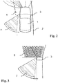
- Figure 2 illustrates the area to the left alongside the vehicle 1.
- Exterior rearview devices 3 are arranged on both sides of the vehicle.
- the rearview devices 3 comprise one or both of a mirror and a display screen.
- the rearview devices 3 further include turn-signal blinkers which illuminate the shaded area 7, which extends in a rearward quadrant between 5 degrees from the longitudinal axis of the vehicle and 55 degrees away from it. This illumination may be achieved with the lights or LEDs for outboard light sector L5 (see Fig 4 ).
- the entire area between the illuminated distributions 16, 21, 23 and 25 of the headlamps is not lit up.
- the adaptive feature of the headlamps is not adaptive enough to light up the area of the roadway immediately adjacent to the vehicle side (e.g. area 6).
- a further light source for light sector L4 is used in the exterior rearview device 3. This light sector L4 illuminates an area 6 which extends at least outwardly from the extension of the exterior mirror or display device 3 to the bodywork contour adjacent the side of the vehicle in front of the rearview device 3.
- Fig. 4 illustrates an example embodiment of an external rearview device 3 for adaptive lighting of a vehicle.
- the rearview device 3 in this example, consists of a mirror head 3a, which comprises a reflecting element on its side which is not visible in the drawing, and a mirror base 3b with which the exterior mirror is mounted on the vehicle 1.
- the vehicle 1 is indicated in the drawing with a sketched contour.
- the exterior mirror 3 contains a lighting module 5 which, in this example, extends along the longitudinal axis of the exterior mirror, which leads away from the vehicle.
- the lighting module 5 may include a turn-signal blinker, a side marker light source, an integrated daytime running light (DRL) and an adaptive cornering light.
- DRL integrated daytime running light
- the integrated daytime running light (DRL), the turn-signal blinker, and the adaptive cornering light include LEDs D1 to D8 arranged to also provide light sectors L4, L5, and L6.
- the light sectors L4, L5, L6 contain LEDs, in order to illuminate areas forward and to the left of the vehicle mirror for the driving situation in which the vehicle is driving along a roadway curving towards the left.
- the functional light sectors L4 to L6 may each share the same LED location (i.e. D1 to D8) as the functional daytime running lights.
- light sector L5 e.g.
- light sector L4 (e.g. which may provide the adaptive cornering light function in some embodiments) shares the same location as daytime running light LED D2; light sector L4 (e.g. which may provide the adaptive cornering light function in some embodiments) shares the same location as daytime running light LED D4, and light sector L6 shares the same location as daytime running light LED D6, and may provide this functionality.
- Fig. 4 schematically illustrates optical elements as semicircular elements.
- the optical elements are utilized to direct the light of each DRL LED and each cornering light LED in a particular direction.
- the optical elements include reflectors, lenses, etc. It should be understood that the lighting module 5 is not limited to the illustrated example embodiment.
- the number of light sectors Lx may be varied, and the arrangement of the light sectors Lx may also be varied, such as horizontally, vertically, diagonally, in a straight line, in a curved line, etc.
- the illumination may be supplied by one or more LEDs or light sources, depending on the complexity desired. If a single light source is used for any given light functionality, the light may be distributed more evenly and broadly by the use of elements such as diffusers, lenses, optical fibers, light guides or wave guides, and/or reflectors. This has a benefit of simpler manufacturing and maintenance of light sources like LEDs, and can still accomplish color and/or intensity variations at the output by means of filters, lenses, or diffusers.
- the lighting module 5 in mirror 3 only contains a turn-signal blinker and an adaptive cornering light.
- a turn-signal blinker and an adaptive cornering light.
- both may, in each case, contain light sources for the other function respectively. Since the blinking function must emit amber-colored light, the LEDs which perform the blinking function are provided only for this specific function.
- the control system for using the adaptive cornering light in the rearview device is important. Since it only makes sense to use the cornering light during sharp turning maneuvers in dim lighting situations, it is expedient to couple the activation of the adaptive cornering light with environmental and vehicle parameters and, in particular, with the daylight levels and vehicle speed. For example, it makes sense to activate the adaptive cornering light in the exterior mirror only below a threshold speed.
- environmental parameters that might be relied upon to activate the adaptive lighting include fog, rain, snow, sleet, cloudy or overcast conditions, and darkness or twilight.
- vehicle parameters that might be relied upon to activate the adaptive lighting include vehicle speed (below a threshold), steering angle (above a threshold), activation of turn indicator signaling an intentions to turn, and activation of daytime running light and/or headlights.
- the lighting module 5 is controlled by means of a control module in the door or a controller in the exterior rearview device, which receives data via a bus system. Input data is fed into the control unit. Said input data includes vehicle data such as, for example, vehicle speed, steering wheel angle, and environmental data, such as road characteristics, illumination levels, weather, etc.
- the control unit then controls each of the adaptive light sectors Lx of the left and right lighting module, independently of each other, to turn on or off each of the LED light sectors and/or to vary their light intensity.
- a useful control system is obtained, if the following vehicle parameters are met:
- This set of parameters defines a sharp turn at low speed in poor visibility and results in the adaptive cornering light being activated.
- a security light function may be provided.
- a security light is also known in the literature as a "puddle light” and generally illuminates one or both sides (70a, 70b) of a vehicle 40 near the doors (see Fig 5 ).
- Security lights have been provided in rearview mirrors 46 and are directed downwards and slight rearwards to illuminate an area 66 and the ground adjacent the side of the vehicle 40.
- Lighting sector L7 (not shown), may be disposed in the bottom side of a rearview device 3 and may be used to illuminate area 66.
- the lighting sector L7 may comprise one or more LEDs or light sources and the illumination may be diffused or directed by optical fibers, lenses, light guides, reflectors, etc. as with any of the other light sectors.
- security lights may be installed in rocker panels, fenders, doors or other exterior locations of the vehicle.
- the security light sector L7 is generally used when the vehicle is stationary, it may also be linked to the turn signal indicator in order to display an arrow or other warning signal along the ground adjacent the vehicle to signal to approaching vehicles or bicycles that the equipped vehicle is about to make a turn procedure.
- US 2005117364 describes a system for displaying arrows along the ground in cooperation with a turn signal to indicate that a turn is intended.
- an interior lighting function may be provided by one or more light sectors L8. While it is possible that light sectors L8 may be housed in the rearview device 3, they may also be housed within the cabin or interior of the vehicle itself. Such interior light may be found in the interior of doors, along flooring or header materials, under the dashboard or under seating, or anywhere else within the interior of a vehicle. Interior lighting, if all associated with one lighting function (such as door opening) may be driven by one light source using optical fibers or light guides to direct the light to each of the output locations. This may have the advantages of reducing light intensity and simplifying maintenance of just a single light source.
- both the security lighting function L7 and the interior lighting function L8 may be "adaptive" to vehicle or environmental conditions. For example, upon sensing an entry remote within a defined proximity at night, a security light may automatically illuminate to direct the user to the vehicle for entry. Interior lighting may operate in a similar manner if desired.
- the illumination may contain a message such as an alert or warning. The message may be selected by a vehicle controller module based on environmental and/or vehicle status conditions. In this case, the message may include an alert such as a weather alert to advise the driver as to fog, snow, sleet, ice or other adverse or dangerous driving conditions.
- the message may be a vehicle status alert such as one warning of low tire pressure or low oil or coolant levels, or a need for service.
- the message may be a logo or graphic design selected by the vehicle manufacturer or by the user.
- the use of images or messages displayed in the illumination area 66 may be accomplished by suitable light sources and patterns or masks that project the message or graphic to the ground area.
- Patent publications US2011/273671 , US2010/253919 , and EP2740632A1 illustrate and describe technology for displaying messages and logos by means of a lighting system such as described above for sector L7.
- the security light and/or the interior lights may be controlled and customized by the user.
- the nature of the illumination may be selected and/or customizable by the user of the vehicle. Some users may prefer red or blue (or any other color) illumination over amber or white.
- the message may be a greeting, such as "Hello” or "Welcome” and may even be customizable to include the user's name if desired. Whether a message is adaptive or user-controlled, it may be the same or different on each side of the vehicle.
- lighting sector L9 may be used to assess the sobriety of a user by means of a reflex test in which the user must, within a predetermined time limit, repeat a displayed pattern of lights, object or numerals, much like the Hasbro game "SIMON.”
- Customization and control of lighting functions may be accomplished by conventional controller electronics such as is currently employed by GM's "Onstar” and Verizon's "HUM” systems. These may use a plug in module or hard wired module having wireless transmitter and receiver functions for communicating with a hand-held user device, such as key fob or smartphone, for example.
- Figure 6 illustrates a simple schematic for a representative control system 30.
- the brain of the control system is a computer controller or processor 32 that receives data inputs from the environmental sensors 34 and the vehicle sensors 36.
- the environmental sensors 34 detect conditions of light or darkness, rain, snow, fog, sleet, road conditions, proximity of a potential driver/user, or proximity an adjacent vehicle, etc. and feed this data to the controller 32.
- the vehicle sensors 36 detect status conditions of the vehicle itself, such as vehicle speed, steering angle, activation of lights (day time running or headlamp), activation of turn signal indicators, activation of hazard flasher lights, engine temperature, engine rpms, engine computer fault detections, oil pressure or life, tire pressure, etc. and feed these to the controller 32.
- status conditions of the vehicle itself such as vehicle speed, steering angle, activation of lights (day time running or headlamp), activation of turn signal indicators, activation of hazard flasher lights, engine temperature, engine rpms, engine computer fault detections, oil pressure or life, tire pressure, etc.
- the processor uses this sensor input to determine which lighting sectors (L4 to L8) to activate, such as the adaptive cornering light sector L4 described above, the turn signal indicator light sector L5, the security light sector L7, or the interior lighting sector L8.
- the controller 32 may receive additional input signals from a remote, hand-held device 38 operated by the user.
- the hand-held user device 38 may be a smartphone having a suitable "app" or a remote key fob adapted to provide special inputs, such as by selecting a mode from a menu and then using up/down or right/left arrows to select the option for each mode, much like a certain camera menus.
- These control signals are shown in dashed lines in Fig. 6 to indicate that they are wirelessly conveyed, such as by a WiFi link or a BluetoothTM technology.
- the user's hand-held device 38 may communicate directly with the receiver of the controller 32, or it may communicate with an application “in the cloud” 39 such as is done with “Onstar” or “Hum,” and the “cloud” application then communicates with the controller 32 to deliver the signals.
- some of the user selected inputs may include any or all of the following:
Landscapes
- Engineering & Computer Science (AREA)
- Mechanical Engineering (AREA)
- Multimedia (AREA)
- Lighting Device Outwards From Vehicle And Optical Signal (AREA)
Applications Claiming Priority (1)
| Application Number | Priority Date | Filing Date | Title |
|---|---|---|---|
| US15/391,026 US10137823B2 (en) | 2011-06-29 | 2016-12-27 | Exterior rearview device with illumination functions |
Publications (2)
| Publication Number | Publication Date |
|---|---|
| EP3342643A1 true EP3342643A1 (fr) | 2018-07-04 |
| EP3342643B1 EP3342643B1 (fr) | 2024-03-27 |
Family
ID=60915273
Family Applications (1)
| Application Number | Title | Priority Date | Filing Date |
|---|---|---|---|
| EP17209110.0A Active EP3342643B1 (fr) | 2016-12-27 | 2017-12-20 | Dispositif de rétroviseur extérieur avec fonctions d'éclairage |
Country Status (2)
| Country | Link |
|---|---|
| EP (1) | EP3342643B1 (fr) |
| CN (1) | CN108237982A (fr) |
Cited By (4)
| Publication number | Priority date | Publication date | Assignee | Title |
|---|---|---|---|---|
| CN112511812A (zh) * | 2020-10-21 | 2021-03-16 | 浙江吉利控股集团有限公司 | 一种车载影音控制系统及方法 |
| CN112644366A (zh) * | 2021-01-07 | 2021-04-13 | 恒大恒驰新能源汽车研究院(上海)有限公司 | 汽车后视镜的照地灯装置 |
| CN113631422A (zh) * | 2019-03-28 | 2021-11-09 | 市光工业株式会社 | 车辆用灯具 |
| CN117440901A (zh) * | 2021-05-31 | 2024-01-23 | 海拉有限双合股份公司 | 用于在至少一个车辆中添加和/或扩展至少一个光源的至少一个光功能的方法 |
Families Citing this family (6)
| Publication number | Priority date | Publication date | Assignee | Title |
|---|---|---|---|---|
| CN109017546B (zh) * | 2018-09-03 | 2019-07-16 | 殷子尧 | 一种用于长轴车转向的激光警示记录装置 |
| FR3087721B1 (fr) * | 2018-10-24 | 2021-07-30 | Valeo Vision | Systeme et procede pour l’eclairage d’une region laterale d’un vehicule |
| CN112389317B (zh) * | 2019-08-02 | 2024-06-28 | 常州星宇车灯股份有限公司 | 一种分段式角灯控制系统及其控制方法 |
| CN113859100B (zh) * | 2020-06-30 | 2023-08-08 | 比亚迪股份有限公司 | 一种车辆的视野辅助系统及其控制方法、车辆 |
| CN117940316B (zh) * | 2021-09-03 | 2024-12-06 | 马格纳电子系统公司 | 具有选择性操作用于dms和oms功能的光发射器的车辆车厢内监测系统 |
| CN116164252A (zh) * | 2021-11-25 | 2023-05-26 | 常州星宇车灯股份有限公司 | 一种车辆侧边辅助照明灯具及工作方法 |
Citations (8)
| Publication number | Priority date | Publication date | Assignee | Title |
|---|---|---|---|---|
| EP1304260A1 (fr) * | 2000-07-12 | 2003-04-23 | Alejandro Rodriguez Barros | Retroviseur modulaire comprenant a signaux multiples interchangeables pour vehicules de 2, 3, 4 roues ou plus |
| US20050117364A1 (en) * | 2003-10-27 | 2005-06-02 | Mark Rennick | Method and apparatus for projecting a turn signal indication |
| EP1564567A1 (fr) * | 2004-02-10 | 2005-08-17 | Murakami Corporation | Dispositif d'éclairage pour véhicules automobiles |
| US20120081915A1 (en) * | 2010-10-01 | 2012-04-05 | Magna Mirrors Of America, Inc. | Vehicle exterior mirror system with light module |
| US20130107557A1 (en) * | 2007-05-03 | 2013-05-02 | Donnelly Corporation | Vehicle exterior door handle with illumination device |
| US20130242586A1 (en) * | 2010-10-01 | 2013-09-19 | Magna Mirrors Of America, Inc. | Vehicle exterior mirror system with light module |
| US20140218946A1 (en) * | 2011-06-29 | 2014-08-07 | SMR Patents S.à.r.I. | Short-Range Cornering Light in an Exterior Mirror |
| WO2016012651A1 (fr) * | 2014-07-24 | 2016-01-28 | Alejandro Rodriguez Barros | Ensemble multifonction à émetteur laser pour la porte d'un véhicule automobile |
Family Cites Families (1)
| Publication number | Priority date | Publication date | Assignee | Title |
|---|---|---|---|---|
| EP2965947B1 (fr) * | 2014-07-11 | 2019-12-25 | SMR Patents S.à.r.l. | Module de clignotant et système de rétroviseur extérieur |
-
2017
- 2017-12-20 EP EP17209110.0A patent/EP3342643B1/fr active Active
- 2017-12-26 CN CN201711436159.8A patent/CN108237982A/zh active Pending
Patent Citations (8)
| Publication number | Priority date | Publication date | Assignee | Title |
|---|---|---|---|---|
| EP1304260A1 (fr) * | 2000-07-12 | 2003-04-23 | Alejandro Rodriguez Barros | Retroviseur modulaire comprenant a signaux multiples interchangeables pour vehicules de 2, 3, 4 roues ou plus |
| US20050117364A1 (en) * | 2003-10-27 | 2005-06-02 | Mark Rennick | Method and apparatus for projecting a turn signal indication |
| EP1564567A1 (fr) * | 2004-02-10 | 2005-08-17 | Murakami Corporation | Dispositif d'éclairage pour véhicules automobiles |
| US20130107557A1 (en) * | 2007-05-03 | 2013-05-02 | Donnelly Corporation | Vehicle exterior door handle with illumination device |
| US20120081915A1 (en) * | 2010-10-01 | 2012-04-05 | Magna Mirrors Of America, Inc. | Vehicle exterior mirror system with light module |
| US20130242586A1 (en) * | 2010-10-01 | 2013-09-19 | Magna Mirrors Of America, Inc. | Vehicle exterior mirror system with light module |
| US20140218946A1 (en) * | 2011-06-29 | 2014-08-07 | SMR Patents S.à.r.I. | Short-Range Cornering Light in an Exterior Mirror |
| WO2016012651A1 (fr) * | 2014-07-24 | 2016-01-28 | Alejandro Rodriguez Barros | Ensemble multifonction à émetteur laser pour la porte d'un véhicule automobile |
Cited By (9)
| Publication number | Priority date | Publication date | Assignee | Title |
|---|---|---|---|---|
| CN113631422A (zh) * | 2019-03-28 | 2021-11-09 | 市光工业株式会社 | 车辆用灯具 |
| EP3950427A4 (fr) * | 2019-03-28 | 2022-12-28 | Ichikoh Industries, Ltd. | Appareil d'éclairage de véhicule |
| US11835191B2 (en) | 2019-03-28 | 2023-12-05 | Ichikoh Industries, Ltd. | Vehicle light fixture |
| CN113631422B (zh) * | 2019-03-28 | 2024-05-07 | 市光工业株式会社 | 车辆用灯具 |
| US12123562B2 (en) | 2019-03-28 | 2024-10-22 | Ichikoh Industries, Ltd. | Vehicle light fixture |
| US12123563B2 (en) | 2019-03-28 | 2024-10-22 | Ichikoh Industries, Ltd. | Vehicle light fixture |
| CN112511812A (zh) * | 2020-10-21 | 2021-03-16 | 浙江吉利控股集团有限公司 | 一种车载影音控制系统及方法 |
| CN112644366A (zh) * | 2021-01-07 | 2021-04-13 | 恒大恒驰新能源汽车研究院(上海)有限公司 | 汽车后视镜的照地灯装置 |
| CN117440901A (zh) * | 2021-05-31 | 2024-01-23 | 海拉有限双合股份公司 | 用于在至少一个车辆中添加和/或扩展至少一个光源的至少一个光功能的方法 |
Also Published As
| Publication number | Publication date |
|---|---|
| CN108237982A (zh) | 2018-07-03 |
| EP3342643B1 (fr) | 2024-03-27 |
Similar Documents
| Publication | Publication Date | Title |
|---|---|---|
| US10137823B2 (en) | Exterior rearview device with illumination functions | |
| US10787177B2 (en) | Exterior rearview device with illumination functions and autonomous vehicles using same | |
| EP3342643B1 (fr) | Dispositif de rétroviseur extérieur avec fonctions d'éclairage | |
| JP7302063B2 (ja) | 画像投射装置および画像投射方法 | |
| JP7389789B2 (ja) | 車両用エンブレムシステム、車両用エンブレムユニット、車両用エンブレム取付ユニット | |
| US10170002B2 (en) | In-vehicle lighting apparatus having a lighting device including a light source in each of the direct and indirect lighting parts thereof | |
| US9527431B2 (en) | Vehicle exterior mirror with adaptively activated forward lighting unit | |
| KR102587258B1 (ko) | 차량의 주행정보 전달 장치 및 방법 | |
| JP2020055374A (ja) | 自動車用照明灯 | |
| CN106794792A (zh) | 车辆用路面绘制系统 | |
| KR20050063726A (ko) | 자동차의 방향 지시 장치 | |
| CN104823122A (zh) | 用于检测明亮的城市条件的成像系统和方法 | |
| US10730427B2 (en) | Lighting device | |
| JP2021154949A (ja) | 車両におけるコミュニケーション支援装置 | |
| US20140153782A1 (en) | Imaging system and method for detecting a winding road | |
| JP2001347881A (ja) | 運転者の顔方向検出装置 | |
| GB2471034A (en) | Self-dimming mirror in a motor vehicle | |
| JP2020185980A (ja) | 車両の旋回警告装置 | |
| CN121822288A (zh) | 远光灯关闭提醒方法及车辆 | |
| CZ308749B6 (cs) | Způsob a systém vizualizace vlnových délek signálů světelného signalizačního zařízení pro vozidla |
Legal Events
| Date | Code | Title | Description |
|---|---|---|---|
| PUAI | Public reference made under article 153(3) epc to a published international application that has entered the european phase |
Free format text: ORIGINAL CODE: 0009012 |
|
| STAA | Information on the status of an ep patent application or granted ep patent |
Free format text: STATUS: THE APPLICATION HAS BEEN PUBLISHED |
|
| AK | Designated contracting states |
Kind code of ref document: A1 Designated state(s): AL AT BE BG CH CY CZ DE DK EE ES FI FR GB GR HR HU IE IS IT LI LT LU LV MC MK MT NL NO PL PT RO RS SE SI SK SM TR |
|
| AX | Request for extension of the european patent |
Extension state: BA ME |
|
| STAA | Information on the status of an ep patent application or granted ep patent |
Free format text: STATUS: REQUEST FOR EXAMINATION WAS MADE |
|
| 17P | Request for examination filed |
Effective date: 20181220 |
|
| RBV | Designated contracting states (corrected) |
Designated state(s): AL AT BE BG CH CY CZ DE DK EE ES FI FR GB GR HR HU IE IS IT LI LT LU LV MC MK MT NL NO PL PT RO RS SE SI SK SM TR |
|
| STAA | Information on the status of an ep patent application or granted ep patent |
Free format text: STATUS: EXAMINATION IS IN PROGRESS |
|
| 17Q | First examination report despatched |
Effective date: 20201026 |
|
| P01 | Opt-out of the competence of the unified patent court (upc) registered |
Effective date: 20230616 |
|
| GRAP | Despatch of communication of intention to grant a patent |
Free format text: ORIGINAL CODE: EPIDOSNIGR1 |
|
| STAA | Information on the status of an ep patent application or granted ep patent |
Free format text: STATUS: GRANT OF PATENT IS INTENDED |
|
| INTG | Intention to grant announced |
Effective date: 20231016 |
|
| GRAS | Grant fee paid |
Free format text: ORIGINAL CODE: EPIDOSNIGR3 |
|
| GRAA | (expected) grant |
Free format text: ORIGINAL CODE: 0009210 |
|
| STAA | Information on the status of an ep patent application or granted ep patent |
Free format text: STATUS: THE PATENT HAS BEEN GRANTED |
|
| AK | Designated contracting states |
Kind code of ref document: B1 Designated state(s): AL AT BE BG CH CY CZ DE DK EE ES FI FR GB GR HR HU IE IS IT LI LT LU LV MC MK MT NL NO PL PT RO RS SE SI SK SM TR |
|
| REG | Reference to a national code |
Ref country code: GB Ref legal event code: FG4D |
|
| REG | Reference to a national code |
Ref country code: CH Ref legal event code: EP |
|
| REG | Reference to a national code |
Ref country code: DE Ref legal event code: R096 Ref document number: 602017080342 Country of ref document: DE |
|
| REG | Reference to a national code |
Ref country code: IE Ref legal event code: FG4D |
|
| PG25 | Lapsed in a contracting state [announced via postgrant information from national office to epo] |
Ref country code: LT Free format text: LAPSE BECAUSE OF FAILURE TO SUBMIT A TRANSLATION OF THE DESCRIPTION OR TO PAY THE FEE WITHIN THE PRESCRIBED TIME-LIMIT Effective date: 20240327 |
|
| REG | Reference to a national code |
Ref country code: LT Ref legal event code: MG9D |
|
| PG25 | Lapsed in a contracting state [announced via postgrant information from national office to epo] |
Ref country code: GR Free format text: LAPSE BECAUSE OF FAILURE TO SUBMIT A TRANSLATION OF THE DESCRIPTION OR TO PAY THE FEE WITHIN THE PRESCRIBED TIME-LIMIT Effective date: 20240628 |
|
| PG25 | Lapsed in a contracting state [announced via postgrant information from national office to epo] |
Ref country code: RS Free format text: LAPSE BECAUSE OF FAILURE TO SUBMIT A TRANSLATION OF THE DESCRIPTION OR TO PAY THE FEE WITHIN THE PRESCRIBED TIME-LIMIT Effective date: 20240627 Ref country code: HR Free format text: LAPSE BECAUSE OF FAILURE TO SUBMIT A TRANSLATION OF THE DESCRIPTION OR TO PAY THE FEE WITHIN THE PRESCRIBED TIME-LIMIT Effective date: 20240327 |
|
| PG25 | Lapsed in a contracting state [announced via postgrant information from national office to epo] |
Ref country code: RS Free format text: LAPSE BECAUSE OF FAILURE TO SUBMIT A TRANSLATION OF THE DESCRIPTION OR TO PAY THE FEE WITHIN THE PRESCRIBED TIME-LIMIT Effective date: 20240627 Ref country code: NO Free format text: LAPSE BECAUSE OF FAILURE TO SUBMIT A TRANSLATION OF THE DESCRIPTION OR TO PAY THE FEE WITHIN THE PRESCRIBED TIME-LIMIT Effective date: 20240627 Ref country code: LT Free format text: LAPSE BECAUSE OF FAILURE TO SUBMIT A TRANSLATION OF THE DESCRIPTION OR TO PAY THE FEE WITHIN THE PRESCRIBED TIME-LIMIT Effective date: 20240327 Ref country code: HR Free format text: LAPSE BECAUSE OF FAILURE TO SUBMIT A TRANSLATION OF THE DESCRIPTION OR TO PAY THE FEE WITHIN THE PRESCRIBED TIME-LIMIT Effective date: 20240327 Ref country code: GR Free format text: LAPSE BECAUSE OF FAILURE TO SUBMIT A TRANSLATION OF THE DESCRIPTION OR TO PAY THE FEE WITHIN THE PRESCRIBED TIME-LIMIT Effective date: 20240628 Ref country code: FI Free format text: LAPSE BECAUSE OF FAILURE TO SUBMIT A TRANSLATION OF THE DESCRIPTION OR TO PAY THE FEE WITHIN THE PRESCRIBED TIME-LIMIT Effective date: 20240327 Ref country code: BG Free format text: LAPSE BECAUSE OF FAILURE TO SUBMIT A TRANSLATION OF THE DESCRIPTION OR TO PAY THE FEE WITHIN THE PRESCRIBED TIME-LIMIT Effective date: 20240327 |
|
| REG | Reference to a national code |
Ref country code: NL Ref legal event code: MP Effective date: 20240327 |
|
| RAP4 | Party data changed (patent owner data changed or rights of a patent transferred) |
Owner name: SMR PATENTS S.A.R.L. |
|
| REG | Reference to a national code |
Ref country code: DE Ref legal event code: R084 Ref document number: 602017080342 Country of ref document: DE |
|
| PG25 | Lapsed in a contracting state [announced via postgrant information from national office to epo] |
Ref country code: SE Free format text: LAPSE BECAUSE OF FAILURE TO SUBMIT A TRANSLATION OF THE DESCRIPTION OR TO PAY THE FEE WITHIN THE PRESCRIBED TIME-LIMIT Effective date: 20240327 Ref country code: LV Free format text: LAPSE BECAUSE OF FAILURE TO SUBMIT A TRANSLATION OF THE DESCRIPTION OR TO PAY THE FEE WITHIN THE PRESCRIBED TIME-LIMIT Effective date: 20240327 |
|
| PG25 | Lapsed in a contracting state [announced via postgrant information from national office to epo] |
Ref country code: NL Free format text: LAPSE BECAUSE OF FAILURE TO SUBMIT A TRANSLATION OF THE DESCRIPTION OR TO PAY THE FEE WITHIN THE PRESCRIBED TIME-LIMIT Effective date: 20240327 |
|
| REG | Reference to a national code |
Ref country code: AT Ref legal event code: MK05 Ref document number: 1669609 Country of ref document: AT Kind code of ref document: T Effective date: 20240327 |
|
| PG25 | Lapsed in a contracting state [announced via postgrant information from national office to epo] |
Ref country code: NL Free format text: LAPSE BECAUSE OF FAILURE TO SUBMIT A TRANSLATION OF THE DESCRIPTION OR TO PAY THE FEE WITHIN THE PRESCRIBED TIME-LIMIT Effective date: 20240327 |
|
| PG25 | Lapsed in a contracting state [announced via postgrant information from national office to epo] |
Ref country code: IS Free format text: LAPSE BECAUSE OF FAILURE TO SUBMIT A TRANSLATION OF THE DESCRIPTION OR TO PAY THE FEE WITHIN THE PRESCRIBED TIME-LIMIT Effective date: 20240727 |
|
| PG25 | Lapsed in a contracting state [announced via postgrant information from national office to epo] |
Ref country code: SM Free format text: LAPSE BECAUSE OF FAILURE TO SUBMIT A TRANSLATION OF THE DESCRIPTION OR TO PAY THE FEE WITHIN THE PRESCRIBED TIME-LIMIT Effective date: 20240327 Ref country code: PT Free format text: LAPSE BECAUSE OF FAILURE TO SUBMIT A TRANSLATION OF THE DESCRIPTION OR TO PAY THE FEE WITHIN THE PRESCRIBED TIME-LIMIT Effective date: 20240729 |
|
| PG25 | Lapsed in a contracting state [announced via postgrant information from national office to epo] |
Ref country code: ES Free format text: LAPSE BECAUSE OF FAILURE TO SUBMIT A TRANSLATION OF THE DESCRIPTION OR TO PAY THE FEE WITHIN THE PRESCRIBED TIME-LIMIT Effective date: 20240327 |
|
| PG25 | Lapsed in a contracting state [announced via postgrant information from national office to epo] |
Ref country code: CZ Free format text: LAPSE BECAUSE OF FAILURE TO SUBMIT A TRANSLATION OF THE DESCRIPTION OR TO PAY THE FEE WITHIN THE PRESCRIBED TIME-LIMIT Effective date: 20240327 Ref country code: EE Free format text: LAPSE BECAUSE OF FAILURE TO SUBMIT A TRANSLATION OF THE DESCRIPTION OR TO PAY THE FEE WITHIN THE PRESCRIBED TIME-LIMIT Effective date: 20240327 |
|
| PG25 | Lapsed in a contracting state [announced via postgrant information from national office to epo] |
Ref country code: AT Free format text: LAPSE BECAUSE OF FAILURE TO SUBMIT A TRANSLATION OF THE DESCRIPTION OR TO PAY THE FEE WITHIN THE PRESCRIBED TIME-LIMIT Effective date: 20240327 |
|
| PG25 | Lapsed in a contracting state [announced via postgrant information from national office to epo] |
Ref country code: PL Free format text: LAPSE BECAUSE OF FAILURE TO SUBMIT A TRANSLATION OF THE DESCRIPTION OR TO PAY THE FEE WITHIN THE PRESCRIBED TIME-LIMIT Effective date: 20240327 |
|
| PG25 | Lapsed in a contracting state [announced via postgrant information from national office to epo] |
Ref country code: SK Free format text: LAPSE BECAUSE OF FAILURE TO SUBMIT A TRANSLATION OF THE DESCRIPTION OR TO PAY THE FEE WITHIN THE PRESCRIBED TIME-LIMIT Effective date: 20240327 |
|
| PG25 | Lapsed in a contracting state [announced via postgrant information from national office to epo] |
Ref country code: SM Free format text: LAPSE BECAUSE OF FAILURE TO SUBMIT A TRANSLATION OF THE DESCRIPTION OR TO PAY THE FEE WITHIN THE PRESCRIBED TIME-LIMIT Effective date: 20240327 Ref country code: SK Free format text: LAPSE BECAUSE OF FAILURE TO SUBMIT A TRANSLATION OF THE DESCRIPTION OR TO PAY THE FEE WITHIN THE PRESCRIBED TIME-LIMIT Effective date: 20240327 Ref country code: RO Free format text: LAPSE BECAUSE OF FAILURE TO SUBMIT A TRANSLATION OF THE DESCRIPTION OR TO PAY THE FEE WITHIN THE PRESCRIBED TIME-LIMIT Effective date: 20240327 Ref country code: PT Free format text: LAPSE BECAUSE OF FAILURE TO SUBMIT A TRANSLATION OF THE DESCRIPTION OR TO PAY THE FEE WITHIN THE PRESCRIBED TIME-LIMIT Effective date: 20240729 Ref country code: PL Free format text: LAPSE BECAUSE OF FAILURE TO SUBMIT A TRANSLATION OF THE DESCRIPTION OR TO PAY THE FEE WITHIN THE PRESCRIBED TIME-LIMIT Effective date: 20240327 Ref country code: IS Free format text: LAPSE BECAUSE OF FAILURE TO SUBMIT A TRANSLATION OF THE DESCRIPTION OR TO PAY THE FEE WITHIN THE PRESCRIBED TIME-LIMIT Effective date: 20240727 Ref country code: ES Free format text: LAPSE BECAUSE OF FAILURE TO SUBMIT A TRANSLATION OF THE DESCRIPTION OR TO PAY THE FEE WITHIN THE PRESCRIBED TIME-LIMIT Effective date: 20240327 Ref country code: EE Free format text: LAPSE BECAUSE OF FAILURE TO SUBMIT A TRANSLATION OF THE DESCRIPTION OR TO PAY THE FEE WITHIN THE PRESCRIBED TIME-LIMIT Effective date: 20240327 Ref country code: CZ Free format text: LAPSE BECAUSE OF FAILURE TO SUBMIT A TRANSLATION OF THE DESCRIPTION OR TO PAY THE FEE WITHIN THE PRESCRIBED TIME-LIMIT Effective date: 20240327 Ref country code: AT Free format text: LAPSE BECAUSE OF FAILURE TO SUBMIT A TRANSLATION OF THE DESCRIPTION OR TO PAY THE FEE WITHIN THE PRESCRIBED TIME-LIMIT Effective date: 20240327 |
|
| PG25 | Lapsed in a contracting state [announced via postgrant information from national office to epo] |
Ref country code: IT Free format text: LAPSE BECAUSE OF FAILURE TO SUBMIT A TRANSLATION OF THE DESCRIPTION OR TO PAY THE FEE WITHIN THE PRESCRIBED TIME-LIMIT Effective date: 20240327 |
|
| PG25 | Lapsed in a contracting state [announced via postgrant information from national office to epo] |
Ref country code: IT Free format text: LAPSE BECAUSE OF FAILURE TO SUBMIT A TRANSLATION OF THE DESCRIPTION OR TO PAY THE FEE WITHIN THE PRESCRIBED TIME-LIMIT Effective date: 20240327 |
|
| REG | Reference to a national code |
Ref country code: DE Ref legal event code: R097 Ref document number: 602017080342 Country of ref document: DE |
|
| PG25 | Lapsed in a contracting state [announced via postgrant information from national office to epo] |
Ref country code: DK Free format text: LAPSE BECAUSE OF FAILURE TO SUBMIT A TRANSLATION OF THE DESCRIPTION OR TO PAY THE FEE WITHIN THE PRESCRIBED TIME-LIMIT Effective date: 20240327 |
|
| PG25 | Lapsed in a contracting state [announced via postgrant information from national office to epo] |
Ref country code: DK Free format text: LAPSE BECAUSE OF FAILURE TO SUBMIT A TRANSLATION OF THE DESCRIPTION OR TO PAY THE FEE WITHIN THE PRESCRIBED TIME-LIMIT Effective date: 20240327 |
|
| PLBE | No opposition filed within time limit |
Free format text: ORIGINAL CODE: 0009261 |
|
| STAA | Information on the status of an ep patent application or granted ep patent |
Free format text: STATUS: NO OPPOSITION FILED WITHIN TIME LIMIT |
|
| 26N | No opposition filed |
Effective date: 20250103 |
|
| PG25 | Lapsed in a contracting state [announced via postgrant information from national office to epo] |
Ref country code: SI Free format text: LAPSE BECAUSE OF FAILURE TO SUBMIT A TRANSLATION OF THE DESCRIPTION OR TO PAY THE FEE WITHIN THE PRESCRIBED TIME-LIMIT Effective date: 20240327 |
|
| PG25 | Lapsed in a contracting state [announced via postgrant information from national office to epo] |
Ref country code: MC Free format text: LAPSE BECAUSE OF FAILURE TO SUBMIT A TRANSLATION OF THE DESCRIPTION OR TO PAY THE FEE WITHIN THE PRESCRIBED TIME-LIMIT Effective date: 20240327 |
|
| REG | Reference to a national code |
Ref country code: CH Ref legal event code: PL |
|
| PG25 | Lapsed in a contracting state [announced via postgrant information from national office to epo] |
Ref country code: LU Free format text: LAPSE BECAUSE OF NON-PAYMENT OF DUE FEES Effective date: 20241220 |
|
| REG | Reference to a national code |
Ref country code: BE Ref legal event code: MM Effective date: 20241231 |
|
| PG25 | Lapsed in a contracting state [announced via postgrant information from national office to epo] |
Ref country code: BE Free format text: LAPSE BECAUSE OF NON-PAYMENT OF DUE FEES Effective date: 20241231 |
|
| PG25 | Lapsed in a contracting state [announced via postgrant information from national office to epo] |
Ref country code: CH Free format text: LAPSE BECAUSE OF NON-PAYMENT OF DUE FEES Effective date: 20241231 |
|
| PG25 | Lapsed in a contracting state [announced via postgrant information from national office to epo] |
Ref country code: IE Free format text: LAPSE BECAUSE OF NON-PAYMENT OF DUE FEES Effective date: 20241220 |
|
| PGFP | Annual fee paid to national office [announced via postgrant information from national office to epo] |
Ref country code: GB Payment date: 20251218 Year of fee payment: 9 |
|
| PGFP | Annual fee paid to national office [announced via postgrant information from national office to epo] |
Ref country code: FR Payment date: 20251218 Year of fee payment: 9 |
|
| PGFP | Annual fee paid to national office [announced via postgrant information from national office to epo] |
Ref country code: DE Payment date: 20251222 Year of fee payment: 9 |