EP3342680A1 - Configuration d'alignement automatique pour des systèmes d'effets mécaniques, hydrauliques et électriques - Google Patents
Configuration d'alignement automatique pour des systèmes d'effets mécaniques, hydrauliques et électriques Download PDFInfo
- Publication number
- EP3342680A1 EP3342680A1 EP17209964.0A EP17209964A EP3342680A1 EP 3342680 A1 EP3342680 A1 EP 3342680A1 EP 17209964 A EP17209964 A EP 17209964A EP 3342680 A1 EP3342680 A1 EP 3342680A1
- Authority
- EP
- European Patent Office
- Prior art keywords
- automatic alignment
- incorporates
- effect system
- connection
- accordance
- Prior art date
- Legal status (The legal status is an assumption and is not a legal conclusion. Google has not performed a legal analysis and makes no representation as to the accuracy of the status listed.)
- Pending
Links
Images
Classifications
-
- B—PERFORMING OPERATIONS; TRANSPORTING
- B62—LAND VEHICLES FOR TRAVELLING OTHERWISE THAN ON RAILS
- B62D—MOTOR VEHICLES; TRAILERS
- B62D13/00—Steering specially adapted for trailers
- B62D13/02—Steering specially adapted for trailers for centrally-pivoted axles
- B62D13/025—Steering specially adapted for trailers for centrally-pivoted axles the pivoted movement being initiated by the coupling means between tractor and trailer
Definitions
- the invention relates to automatic alignment setup of Lowbed, Low Loader and modular vehicle types with hydro-mechanical steering systems and used for heavy load transportation.
- the said invention is characterized in that it is able to perform automatic alignment with any angle between the tractor and trailer and primarily relates to an automatic alignment setup with simpler structure compared to those utilized in existing systems.
- Closed loop steering systems move the wheels of the trailer to an angle proper to that of tractor movement depending on steering angle of the tractor. It performs this in all steering angles of the tractor by means of hydraulic cylinders.
- This proper positioning of trailer wheels according to Ackerman Principle is provided with the dimensions of hydraulic cylinders during design stage. There are 4 hydraulic cylinders in total on a trailer, two being on the fifth wheel and two being on axle part. In a closed loop, the front and rear cylinders operate dependently on each other. However, when trailer wheels are turned manually with electro-hydraulic engine drive, the positions of front and rear cylinders are disrupted per Ackerman Principle. Restoring the positions to their original state is called Alignment.
- Closed loop steering systems have two types of alignment systems, full automatic and semi automatic. Both systems have advantages over each other. However, the biggest disadvantage with both systems is that the tractor is not able to perform alignment in all angles. The tractor performs alignment only in certain angles or when straight.
- the shortcomings and inadequacy of these applications are as follows.
- Full automatic alignment system works as follows. There is an angle sensor (potentiometer) on the fifth wheel calculating the angle between the tractor and trailer. Likewise, there is an angle sensor (potentiometer) on steering hub in order to calculate the angles of trailer wheels. The angle sensor on the fifth wheel is used as input while the angle sensor on the steering hub is used as feedback provider.
- angle sensor potentiometer
- microcontrollers On this system, one or multiple microcontrollers (ECU) are used.
- a transfer function formed previously to ensure Ackerman Principle depending on trailer length and steering angles of wheels on steering axle, is installed on the microcontroller (ECU).
- ECU microcontroller
- a transfer function formed previously to ensure Ackerman Principle depending on trailer length and steering angles of wheels on steering axle, is installed on the microcontroller (ECU).
- ECU microcontroller
- the wheels are turned left or right by means of electro-hydraulic pump according to the value calculated with this calculation. Turning process continues until the wheels achieve the correct angle. The fact that the wheels are at correct angle is verified with the information received from the angle sensor at the axle part.
- Full automatic alignment system also possesses the following technical inadequacies.
- ECU Electronic controller units
- the electronic controller units manufactured to be resistant to the said environmental disruptive factors have high costs.
- Semi automatic alignment system works as follows. There are two lamps on front left and front right of trailer. These lamps indicate, for the driver, whether the trailer is turned towards right or left. This is performed by the two inductive sensors located on the fifth wheel however not turning with fifth wheel. These sensors follow a special bracket welded on the fifth wheel. When tractor turns right, the lamp on the right turns on while the one on the left turns off. Likewise, when the tractor turns left, the lamp on the left turns on while the one on the right turns off. The lamps are turned on at the same time only when the angle between the trailer and tractor is 0°, in other words, they are straight.
- lamps On the wired control box, there are two lamps, one for right and one for left. These lamps show to the operator if the trailer wheels are turned right or left. If the lamps are turned on at the same time, this indicates that the trailer wheels are straight.
- Semi automatic alignment system only performs automatic alignment when the angle between tractor and trailer is 0°. It will not work otherwise. When the angle between trailer and tractor is 0°, two lamps on the left and right of gooseneck will also light up. Driver can only use automatic alignment when these lamps are on at the same time.
- the main purpose of the invention is to make automatic alignment system work at any angle between tractor and trailer.
- An important purpose of the invention is to turn a mechanical guide located at axle part synchronously with steering motion of tractor.
- the movement of mechanical guide is controlled at axle area and automatic alignment is performed.
- the steering motion of tractor can be transfered to axle in 3 different forms. These are: mechanical, hydraulic and electrical methods.
- the purpose of the invention is reduction of material cost through usage of electrical control circuit (electrical logic circuit) consisting of relays used in electric circuits and digital signal output inductive sensors instead of electronic controller unit and analog signal output angle sensors used in full automatic alignment systems.
- electrical control circuit electrical logic circuit
- the purpose of the invention is to present an electrical design that is simpler compared to both full automatic alignment system and semi automatic alignment system.
- the purpose of the invention is to allow much less material usage compared to both systems. This translates into more employment in manufacture and faster production processes through cost reductions.
- the purpose of the invention is to provide more accurate and consistent operation compared to light indicated automatic alignment system, electronic controller system.
- the purpose of the invention is usage more suited to outdoor environment conditions.
- the purpose of the invention is to present an easier and more successful setup in terms of diagnostics and troubleshooting.
- the invention is an automatic alignment setup that is able to perform automatic alignment at any angle between tractor and trailers used in heavy load transportation and that has at least one fifth wheel and a gooseneck with at least two connection points set up on this fifth wheel, and it is characterized in that it incorporates;
- the automatic alignment setup that is able to perform automatic alignment at any angle between tractor and trailers used in heavy load transportation and that has at least one fifth wheel (1.2) and a gooseneck (1.3.1) with at least two connection points set up on this fifth wheel (1.2) is illustrated;
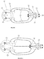
- the said automatic alignment setup (1) incorporates a mechanical effect system (4) with connection wires (4.5) secured at at least two points between the said fifth wheel (1.2) and steering hub (18).
- FIG-3 top general view of the electrical efffect system (3) is illustrated. It consists of the electric effect system (3) with servo motor (3.6), angle sensor (3.1) and securing shaft (3.2) set up between the said fifth wheel (1.2) and steering hub (18). It shows the angle sensor electrical cable, mechanical guide wire connection (3.8) and servo motor electrical cable (3.5) of this electrical effect system (3) and at least one servo driver (3.4) of the said electrical effect system (3). It illustrates connection wire (3.8) and one shaft securing point (3.9) and angle sensor cylinder (3.10) of this electrical effect system (3).
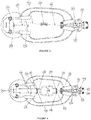
- Figure-4 demonstrates the hydraulic effect system (2). It shows the hydraulic effect system (2) with fifth wheel wire connections (2.1) and connection wires (2.2) secured at at least two points, front cylinder (2.5), rear cylinder (2.6) and inductive sensors (2.10), set up between the said fifth wheel (1.2) and steering hub (18). It has the front movement transfer bracket center (2.3) front movement transfer bracket wire connection (2.4) and front movement transfer bracket wire connection (2.7) of this hydraulic effect system (2). In addition, it shows the guide pin (2.8), mechanical guide wire connection pin (2.9), mechanical guide (2.11) and mechanical guide center of rotation (2.12) of the said hydraulic effect system (2).
- connection wires (4.5) made of steel material.
- connection pins (4.1) secured on fifth wheel (1.2) and rotating with fifth wheel (1.2).
- mechanical guide wire connection pins (4.4) on the mechanical guide (2.11) located at steering center (1.6).
- the wires (4.5) connected to the connection pins (4.1) at the front are guided via gude pins (4.2, 4.3) and connected to the rear mechanical guide wire connection pins (4.4).
- the tension of the wires (2.13) must be same.
- connection wire (2.13) is installed between the front movement transfer bracket wire connections (2.7) on rear movement transfer bracket (2.14) and the mechanical guide wire connection pin (2.9) on mechanical guide (2.11).
- mechanical guide (2.11) will also turn accordingly.
- steering action of tractor will turn the mechanical guide (2.11) through hydraulic front and rear cylinders (2.5, 2.6).
- Steering hub (1.8) turns towards the direction to which the user turns the wheels. Meanwhile, the inductive sensors (2.10) connected to the sensor connection brackets (2.19) will also turn. Inductive sensors (2.10) connected on the connection bracket are passive prior to movement. After movement starts, the sensor at the opposite side of the direction towards which the wheel moves will be activated. Activation of this sensor allows the electrical system to perceive towards which direction does the wheel turn.
- the user wishes to align the wheels, it will be sufficient to only press the automatic alignment button once.
- electrical system will start to turn the wheels towards the opposite direction of the active sensor. This turning action will continue until the active sensor turns passive. When the turning action stops, the vehicle would be aligned.
Landscapes
- Engineering & Computer Science (AREA)
- Chemical & Material Sciences (AREA)
- Combustion & Propulsion (AREA)
- Transportation (AREA)
- Mechanical Engineering (AREA)
- Steering Control In Accordance With Driving Conditions (AREA)
Applications Claiming Priority (1)
| Application Number | Priority Date | Filing Date | Title |
|---|---|---|---|
| TR201620358 | 2016-12-30 |
Publications (1)
| Publication Number | Publication Date |
|---|---|
| EP3342680A1 true EP3342680A1 (fr) | 2018-07-04 |
Family
ID=61002774
Family Applications (1)
| Application Number | Title | Priority Date | Filing Date |
|---|---|---|---|
| EP17209964.0A Pending EP3342680A1 (fr) | 2016-12-30 | 2017-12-22 | Configuration d'alignement automatique pour des systèmes d'effets mécaniques, hydrauliques et électriques |
Country Status (1)
| Country | Link |
|---|---|
| EP (1) | EP3342680A1 (fr) |
Citations (4)
| Publication number | Priority date | Publication date | Assignee | Title |
|---|---|---|---|---|
| US4702488A (en) * | 1984-12-14 | 1987-10-27 | Atlantic Richfield Company | Steering system for tractor-trailer units |
| EP1640247A1 (fr) * | 2004-09-23 | 2006-03-29 | Renders SA | Semi-remorque ou remorque avec contrôle de direction améliorée |
| US20130175785A1 (en) * | 2010-09-21 | 2013-07-11 | Renders S.A. | Steering mechanism for a drawn vehicle to steer one or more turnable steered axles |
| EP3187397A2 (fr) * | 2015-12-31 | 2017-07-05 | Tirsan Treyler Sanayi Ve Ticaret Anonim Sirketi | Système d'alignement automatique au moyen d'une lumière d'avertissement |
-
2017
- 2017-12-22 EP EP17209964.0A patent/EP3342680A1/fr active Pending
Patent Citations (4)
| Publication number | Priority date | Publication date | Assignee | Title |
|---|---|---|---|---|
| US4702488A (en) * | 1984-12-14 | 1987-10-27 | Atlantic Richfield Company | Steering system for tractor-trailer units |
| EP1640247A1 (fr) * | 2004-09-23 | 2006-03-29 | Renders SA | Semi-remorque ou remorque avec contrôle de direction améliorée |
| US20130175785A1 (en) * | 2010-09-21 | 2013-07-11 | Renders S.A. | Steering mechanism for a drawn vehicle to steer one or more turnable steered axles |
| EP3187397A2 (fr) * | 2015-12-31 | 2017-07-05 | Tirsan Treyler Sanayi Ve Ticaret Anonim Sirketi | Système d'alignement automatique au moyen d'une lumière d'avertissement |
Similar Documents
| Publication | Publication Date | Title |
|---|---|---|
| AU2020200847C1 (en) | Alignment of steering controller angle and machine steering angle for transitioning between manual and autonomous operating modes | |
| US10004171B2 (en) | Assembly comprising a chassis for a variable-track machinery equipment such as a sprayer-type agricultural machinery equipment or a straddle machinery equipment | |
| US20160144890A1 (en) | Steering control method and apparatus for steer-by-wire system | |
| US11273861B2 (en) | Hydraulic steering system | |
| CN105313956B (zh) | 一种具有冗余功能的汽车前轮独立控制液压转向系统 | |
| EP3681784A1 (fr) | Synchronisation d'actionneur dans un système de direction à commande électrique | |
| US11318986B2 (en) | Steering device | |
| CN104015788A (zh) | 工程车辆及其电液转向系统 | |
| CN205499046U (zh) | 一种自动驾驶转向控制系统 | |
| AU2011240163A1 (en) | Steering method and steering system for an industrial truck | |
| EP3797059A1 (fr) | Procédé de commande d'un système de direction à commande électrique à mode de fonctionnement de secours | |
| EP3042827A2 (fr) | Système de direction présentant deux rapports de direction | |
| EP3533688B1 (fr) | Système de direction active destiné à être utilisé dans une machine de levage, machine de levage | |
| EP2042407B1 (fr) | Véhicule agricole avec son sytème de direction | |
| CN103625546A (zh) | 辅助助力转向控制方法、装置和车辆 | |
| CN205168619U (zh) | 一种具有冗余功能的汽车前轮独立控制液压转向系统 | |
| CN111055915A (zh) | 一种双控转向装置及起重机 | |
| EP3342680A1 (fr) | Configuration d'alignement automatique pour des systèmes d'effets mécaniques, hydrauliques et électriques | |
| CN112977600A (zh) | 转向系统和车辆 | |
| DE102012112743A1 (de) | Lenkverfahren und Flurförderzeug | |
| DE102006035863A1 (de) | Lenkvorrichtung für ein Flurförderzeug | |
| RU2668771C2 (ru) | Рулевое управление транспортного средства повышенной проходимости | |
| EP1697201B1 (fr) | Procede et produit informatique dans un dispositif de conduite de vehicule | |
| CN114771637B (zh) | 一种可用于远程-本地控制的电液转向系统 | |
| JP3038771B2 (ja) | 四輪操舵制御装置 |
Legal Events
| Date | Code | Title | Description |
|---|---|---|---|
| PUAI | Public reference made under article 153(3) epc to a published international application that has entered the european phase |
Free format text: ORIGINAL CODE: 0009012 |
|
| STAA | Information on the status of an ep patent application or granted ep patent |
Free format text: STATUS: THE APPLICATION HAS BEEN PUBLISHED |
|
| AK | Designated contracting states |
Kind code of ref document: A1 Designated state(s): AL AT BE BG CH CY CZ DE DK EE ES FI FR GB GR HR HU IE IS IT LI LT LU LV MC MK MT NL NO PL PT RO RS SE SI SK SM TR |
|
| AX | Request for extension of the european patent |
Extension state: BA ME |
|
| STAA | Information on the status of an ep patent application or granted ep patent |
Free format text: STATUS: REQUEST FOR EXAMINATION WAS MADE |
|
| 17P | Request for examination filed |
Effective date: 20181001 |
|
| RBV | Designated contracting states (corrected) |
Designated state(s): AL AT BE BG CH CY CZ DE DK EE ES FI FR GB GR HR HU IE IS IT LI LT LU LV MC MK MT NL NO PL PT RO RS SE SI SK SM TR |
|
| STAA | Information on the status of an ep patent application or granted ep patent |
Free format text: STATUS: EXAMINATION IS IN PROGRESS |
|
| 17Q | First examination report despatched |
Effective date: 20190409 |