EP3342747A1 - Zuführungsstruktur für gabelstapler - Google Patents
Zuführungsstruktur für gabelstapler Download PDFInfo
- Publication number
- EP3342747A1 EP3342747A1 EP17209174.6A EP17209174A EP3342747A1 EP 3342747 A1 EP3342747 A1 EP 3342747A1 EP 17209174 A EP17209174 A EP 17209174A EP 3342747 A1 EP3342747 A1 EP 3342747A1
- Authority
- EP
- European Patent Office
- Prior art keywords
- battery
- charger
- power supply
- batteries
- terminal block
- Prior art date
- Legal status (The legal status is an assumption and is not a legal conclusion. Google has not performed a legal analysis and makes no representation as to the accuracy of the status listed.)
- Granted
Links
Images

Classifications
-
- B—PERFORMING OPERATIONS; TRANSPORTING
- B66—HOISTING; LIFTING; HAULING
- B66F—HOISTING, LIFTING, HAULING OR PUSHING, NOT OTHERWISE PROVIDED FOR, e.g. DEVICES WHICH APPLY A LIFTING OR PUSHING FORCE DIRECTLY TO THE SURFACE OF A LOAD
- B66F9/00—Devices for lifting or lowering bulky or heavy goods for loading or unloading purposes
- B66F9/06—Devices for lifting or lowering bulky or heavy goods for loading or unloading purposes movable, with their loads, on wheels or the like, e.g. fork-lift trucks
- B66F9/075—Constructional features or details
- B66F9/20—Means for actuating or controlling masts, platforms, or forks
- B66F9/24—Electrical devices or systems
-
- B—PERFORMING OPERATIONS; TRANSPORTING
- B66—HOISTING; LIFTING; HAULING
- B66F—HOISTING, LIFTING, HAULING OR PUSHING, NOT OTHERWISE PROVIDED FOR, e.g. DEVICES WHICH APPLY A LIFTING OR PUSHING FORCE DIRECTLY TO THE SURFACE OF A LOAD
- B66F9/00—Devices for lifting or lowering bulky or heavy goods for loading or unloading purposes
- B66F9/06—Devices for lifting or lowering bulky or heavy goods for loading or unloading purposes movable, with their loads, on wheels or the like, e.g. fork-lift trucks
- B66F9/075—Constructional features or details
- B66F9/07513—Details concerning the chassis
- B66F9/07531—Battery compartments
-
- B—PERFORMING OPERATIONS; TRANSPORTING
- B66—HOISTING; LIFTING; HAULING
- B66F—HOISTING, LIFTING, HAULING OR PUSHING, NOT OTHERWISE PROVIDED FOR, e.g. DEVICES WHICH APPLY A LIFTING OR PUSHING FORCE DIRECTLY TO THE SURFACE OF A LOAD
- B66F9/00—Devices for lifting or lowering bulky or heavy goods for loading or unloading purposes
- B66F9/06—Devices for lifting or lowering bulky or heavy goods for loading or unloading purposes movable, with their loads, on wheels or the like, e.g. fork-lift trucks
- B66F9/075—Constructional features or details
- B66F9/07513—Details concerning the chassis
- B66F9/0754—Battery removal arrangements
Definitions
- the present description relates generally to the power supply systems and, more particularly, to the production of a power supply structure for a forklift truck.
- a forklift needs a source of energy.
- a first category of trolleys is equipped with thermal engines.
- a second category to which this description applies is equipped with a power supply structure consisting of rechargeable batteries.
- a traditional power supply structure consists of a battery pack comprising lead batteries housed in a handling box and interconnected so as to have only two terminals (positive and negative) for connecting the battery pack or the electric motor of the battery pack.
- trolley either to a battery charger external to the trolley.
- the feeding structure is particularly bulky and heavy.
- EP-A-2,700,611 discloses a forklift battery, in which a plurality of battery modules 17, individually associated with management devices 18, are connected to a controller 20 of the battery.
- the battery is connected to the outside by a cable 24.
- One embodiment provides a power supply structure of a forklift that overcomes all or part of the disadvantages of current structures.
- One embodiment provides a solution compatible with forklifts designed to use lead-acid battery packs.
- said connecting element comprises a connection cable of the charger to the electricity distribution network.
- the charger comprises a galvanic transformer at the frequency of the electrical network, the transformer participating in ballast the forklift.
- the box is filled with oil.
- the structure comprises at least one energy storage module having two connection terminals, each module comprising a battery and a bidirectional converter, the bidirectional converter being connected on the one hand to the associated battery and to the other. on the other hand to the connection terminals of the module.
- the bidirectional converter serves as a DC / DC converter during the load periods to transfer power from the network to the module's battery, and serves as a DC / DC converter during the periods of time. discharge to transfer power from the battery to a power terminal of the truck.
- the discharge of the battery pack is controlled to emulate a discharge of the lead battery (s).
- One embodiment provides a lift truck having a power supply structure.
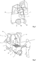
- the figure 1 is a perspective representation of a forklift.
- the figure 2 is a perspective representation of a forklift and a conventional battery pack being installed.
- a forklift 1 consists of a frame 12, carrying the various equipment (engine, transmission, lifting system 14, seat 16, etc.), and mounted on wheels 18.
- the frame 12 also carries a battery pack 2, housed under the seat 16.
- the seat is articulated on a support 17 capable of pivoting to allow the installation of the battery pack 2 (see figure 2 ).
- the set 22 of lead batteries is housed in a palletizable box 3, in which these batteries are interconnected. Recharging the batteries in a conventional trolley requires extracting the crate 3, transporting it to a charging zone and charging the battery pack 2.
- the figure 3 is a schematic perspective view of an embodiment of a lithium battery power supply structure 4 of a forklift.
- the figure 4 is a simplified block diagram of the embodiment of the figure 3 and its connection to the motor of the electric cart.
- the figure 5 illustrates another representation of the equivalent electric diagram of an embodiment of a structure 4 of power supply of a forklift.
- the box 5 is typically a rectangular parallelepipedic enclosure made of steel, preferably provided with a lid.
- the links of the various elements have been illustrated in dashed lines.
- the cable 48 (or alternatively the plug) extends (or is connected) to the charger (link 52), the DC output of the charger 44 is connected (link 54) to the common terminals of the batteries of the set 42 which are also connected to the terminal block 46 (link 56).
- the links comprise, in addition to the son carrying the energy (the power), son (not shown) carrying control signals.
- switches and / or control circuits can be interposed on all or part of the links.
- a control circuit 62 CTRL
- CTRL control circuit 62
- PI inverter 64
- M motor 66
- a positive lead 54-p connects the battery pack 42 to the charger 44 (LOAD).
- Negative conductors 54-n and 56-n connect the battery pack 42 respectively to the inverter 64 and the charger 44.
- the volume available inside the body 5 is used to ballast the structure.
- it preserves the counterweight function of the usual battery packs.
- metal or cast iron ballasts are provided.
- ballast consists of oil (the box is filled with oil), which contributes to improving the cooling, the oil being a good thermal conductor.
- the space is occupied by one or more batteries connected in parallel to form the set of batteries 42.
- the management of modules or set of redundancy batteries is in itself known.
- the charger 44 comprises a galvanic transformer at the mains frequency (50Hz or 60Hz) rather than a switching converter to participate in the ballast.
- the mains frequency 50Hz or 60Hz
- this type of transformer is generally seen as a disadvantage because of the weight and bulk, this disadvantage is transformed into an advantage.
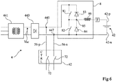
- the figure 6 represents, very schematically, another embodiment of a feed structure 4.
- the chopper function of the charger is used bi-directionally, that is to say, a step-down during the load and an elevator during the discharge or vice versa.
- the chopper 8 is shown schematically in the form of two switches 81 and 82 in series between the output terminals 445 and 447 of the rectifier 443, each switch 81, 82 being in parallel with a diode 83, respectively 84.
- the midpoint 85 of the series linking of the switches 81 and 82 is connected, via an inductive element 86, to a terminal, for example positive 42-p, of the battery assembly 42.
- the terminal 447 is common to the terminal negative 42-n of the battery pack 42.
- the anodes of the diodes 83 and 84 are respectively connected to the terminals 85 and 42-n.
- the output of the rectifier 443 is also connected to the control circuit 62 (the conductors 56-p and 56-n are respectively connected to the terminals 445 and 447).
- the chopper 8 serves not only as a DC / DC converter during the charging phases, but also as a DC / DC converter during the discharge phases.
- MS-i storage consisting of a BAT-i battery and an 8-i converter.
- the bidirectional chopper 8-i is adapted, on the one hand, to the voltage of the associated BAT-i battery, for example 12 or 24 volts and, on the other hand, to the common voltage applied between them. terminals 445 and 447, for example 24V, 48V and 80V.
- This modular embodiment also has the advantage of ensuring redundancy of the batteries and the DC / DC converter part, a faulty module that can easily be compensated by the other non-faulty modules.
- fuse type safety elements (not shown) F can be provided between the chopper 8 and the battery assembly 42 and / or between the chopper and the terminal 445.
- the transformer and the rectifier are elements unlikely to present a failure, they can advantageously be common to all modules.
- Another advantage of using a bidirectional chopper is that the continuous / continuous conversion during use of the lift truck makes it possible to emulate and restore the operation of a lead acid battery. Indeed, we know the evolution of the voltage depending on the state of charge (SoC) for a lead battery and a lithium battery.
- SoC state of charge
- the setpoint of the chopper can be adapted according to the state of charge measured at the terminals of the battery pack 42 (such a measurement is in itself usual) of the module and of a correspondence table between a state of charge. equivalent of a lead-acid battery and that of a lithium battery.
- An advantage of the embodiments that have been described is that it is now possible to maintain a fleet of forklifts while benefiting from lithium batteries.
- Another advantage is that the change from a lead structure to a lithium structure is particularly simple. Simply remove the lead-acid battery case and replace the case 5 of the lithium battery structure instead.
- Another advantage is that the presence of the charger in the supply structure allows to directly connect the structure to the electricity distribution network, the AC-DC conversion being carried out in the structure.
- Another advantage of the presence of the charger in the structure, in particular by using a galvanic transformer, is that it contributes to the weight of the truck.
- the batteries used are lithium batteries. Nevertheless, other types of batteries having similar properties can be used, for example Sodium-Ion-based batteries.
- the batteries In order to be able to present the aforementioned advantages and be interesting in the context of a retrofit process, the batteries must be able to be charged quickly, in one hour or two hours.
- Fast charging means batteries that can be recharged at least twice as fast, or 5 or 10 times faster than so-called slow charge batteries such as lead-acid batteries.
- slow charge batteries such as lead-acid batteries.
- batteries used in the examples described may, in a conventional manner, consist of several elementary electrochemical cells placed in series and / or parallel.
- the charger 44 is in practice controlled by a controller not shown, which will control the start of the charger when the connecting element 48 is connected to the electrical distribution network.
- the start of the charger 44 will be accompanied by an opening of the control circuit (CTRL) 62, in particular to avoid any risk of undesirable start of the carriage causing disconnection or inadvertent damage to the connecting element .
- CTRL control circuit
Landscapes
- Engineering & Computer Science (AREA)
- Transportation (AREA)
- Structural Engineering (AREA)
- Civil Engineering (AREA)
- Life Sciences & Earth Sciences (AREA)
- Geology (AREA)
- Mechanical Engineering (AREA)
- Chemical & Material Sciences (AREA)
- Combustion & Propulsion (AREA)
- Charge And Discharge Circuits For Batteries Or The Like (AREA)
- Electric Propulsion And Braking For Vehicles (AREA)
- Forklifts And Lifting Vehicles (AREA)
Applications Claiming Priority (1)
| Application Number | Priority Date | Filing Date | Title |
|---|---|---|---|
| FR1663511A FR3061489B1 (fr) | 2016-12-29 | 2016-12-29 | Structure d'alimentation pour chariot elevateur |
Publications (2)
| Publication Number | Publication Date |
|---|---|
| EP3342747A1 true EP3342747A1 (de) | 2018-07-04 |
| EP3342747B1 EP3342747B1 (de) | 2019-07-31 |
Family
ID=58547624
Family Applications (1)
| Application Number | Title | Priority Date | Filing Date |
|---|---|---|---|
| EP17209174.6A Active EP3342747B1 (de) | 2016-12-29 | 2017-12-20 | Zuführungsstruktur für gabelstapler |
Country Status (3)
| Country | Link |
|---|---|
| EP (1) | EP3342747B1 (de) |
| DK (1) | DK3342747T3 (de) |
| FR (1) | FR3061489B1 (de) |
Citations (2)
| Publication number | Priority date | Publication date | Assignee | Title |
|---|---|---|---|---|
| US20100279153A1 (en) * | 2009-04-30 | 2010-11-04 | Lg Chem, Ltd. | Battery systems, battery module, and method for cooling the battery module |
| EP2700611A1 (de) * | 2012-08-21 | 2014-02-26 | STILL GmbH | Adapterrahmen für Traktionsbatterie sowie Flurförderzeug mit Traktionsbatterie |
Family Cites Families (4)
| Publication number | Priority date | Publication date | Assignee | Title |
|---|---|---|---|---|
| DE19956623C2 (de) * | 1999-11-25 | 2003-04-17 | Jungheinrich Ag | Batterie und Batterieaufnahme in einem Flurförderzeug, Transportgerät zum Wechseln der Batterie und Ladegerät für die Batterie |
| FR2966111A1 (fr) * | 2010-10-18 | 2012-04-20 | Ba Systemes | Vehicule automobile presentant des moyens de remplacement automatique d'une batterie d'accumulateurs, procede de substitution de batterie, batterie et dispositif de chargement d'un accumulateur de batterie correspondants |
| US20130260195A1 (en) * | 2012-04-02 | 2013-10-03 | Shijin Long | Oil-cooled lithium battery module |
| DE102013114944A1 (de) * | 2013-12-30 | 2015-07-16 | Linde Material Handling Gmbh | Flurförderzeug mit Traktionsbatterie |
-
2016
- 2016-12-29 FR FR1663511A patent/FR3061489B1/fr active Active
-
2017
- 2017-12-20 EP EP17209174.6A patent/EP3342747B1/de active Active
- 2017-12-20 DK DK17209174.6T patent/DK3342747T3/da active
Patent Citations (2)
| Publication number | Priority date | Publication date | Assignee | Title |
|---|---|---|---|---|
| US20100279153A1 (en) * | 2009-04-30 | 2010-11-04 | Lg Chem, Ltd. | Battery systems, battery module, and method for cooling the battery module |
| EP2700611A1 (de) * | 2012-08-21 | 2014-02-26 | STILL GmbH | Adapterrahmen für Traktionsbatterie sowie Flurförderzeug mit Traktionsbatterie |
Also Published As
| Publication number | Publication date |
|---|---|
| FR3061489A1 (fr) | 2018-07-06 |
| FR3061489B1 (fr) | 2020-11-06 |
| EP3342747B1 (de) | 2019-07-31 |
| DK3342747T3 (da) | 2019-08-26 |
Similar Documents
| Publication | Publication Date | Title |
|---|---|---|
| EP3066739B1 (de) | Verfahren zum laden von einem elektrofahrzeug zu einem elektrofahrzeug | |
| EP3758969B1 (de) | Versorgungsmodul für einen elektrofahrzeugmotor | |
| EP2774240B1 (de) | Vorrichtung zum ausgleich der ladung von elementen einer strombatterie | |
| EP2935003B1 (de) | Betankungsvorrichtung im flug für elektrisches speichersystem und flugzeug mit einer derartigen vorrichtung | |
| EP2875572A2 (de) | Multidirektionaler umrichter mit einem einzelnen transformator und drei anschlüssen für elektrofahrzeuge | |
| EP2372864B1 (de) | Autonomes Motorisierungssystem | |
| US20200331354A1 (en) | Electric vehicle (ev) fast recharge station and system | |
| EP3065969A1 (de) | Kompakte ladevorrichtung für ein elektrofahrzeug | |
| EP4038716B1 (de) | Elektrisches ladegerät für aeronautische wartungseinrichtung | |
| WO2013132018A1 (fr) | Dispositif de charge comprenant un convertisseur dc-dc | |
| EP3389175B1 (de) | Umwandlungsvorrichtung, entsprechendes steuerverfahren und entsprechendes fahrzeug | |
| FR3095090A1 (fr) | Procédé et dispositif de contrôle de l’hybridation d’un aéronef | |
| EP3342747B1 (de) | Zuführungsstruktur für gabelstapler | |
| WO2022200497A1 (fr) | Dispositif autonome d'alimentation électrique, notamment pour charger une batterie | |
| EP3981056B1 (de) | Wiederaufladbare elektrische energiespeichervorrichtung und system, fahrzeug und anlage mit einem solchen system | |
| WO2019166732A2 (fr) | Module d'alimentation pour moteur de véhicule électrique, avec transfert thermique | |
| CA3024397A1 (fr) | Procede et systeme de gestion intelligente de batteries electrochimiques d'un vehicule electrique | |
| EP3123591A1 (de) | Fahrzeug mit bordvorrichtung, insbesondere einer kryogenen vorrichtung, und verbindungsvorrichtung zur elektrischen stromversorgung dieser vorrichtung | |
| FR3162399A1 (fr) | Systeme electrique de transfert de puissance pour un vehicule electrifie | |
| WO2020002820A1 (fr) | Système de stockage d'énergie embarqué | |
| FR3058601A1 (fr) | Installation photovoltaique de site industriel avec dispositif de stockage de l’energie sur des chariots de manutention |
Legal Events
| Date | Code | Title | Description |
|---|---|---|---|
| PUAI | Public reference made under article 153(3) epc to a published international application that has entered the european phase |
Free format text: ORIGINAL CODE: 0009012 |
|
| STAA | Information on the status of an ep patent application or granted ep patent |
Free format text: STATUS: REQUEST FOR EXAMINATION WAS MADE |
|
| 17P | Request for examination filed |
Effective date: 20171220 |
|
| AK | Designated contracting states |
Kind code of ref document: A1 Designated state(s): AL AT BE BG CH CY CZ DE DK EE ES FI FR GB GR HR HU IE IS IT LI LT LU LV MC MK MT NL NO PL PT RO RS SE SI SK SM TR |
|
| AX | Request for extension of the european patent |
Extension state: BA ME |
|
| GRAP | Despatch of communication of intention to grant a patent |
Free format text: ORIGINAL CODE: EPIDOSNIGR1 |
|
| STAA | Information on the status of an ep patent application or granted ep patent |
Free format text: STATUS: GRANT OF PATENT IS INTENDED |
|
| RIC1 | Information provided on ipc code assigned before grant |
Ipc: B66F 9/075 20060101AFI20181130BHEP Ipc: B66F 9/24 20060101ALI20181130BHEP |
|
| INTG | Intention to grant announced |
Effective date: 20190108 |
|
| GRAJ | Information related to disapproval of communication of intention to grant by the applicant or resumption of examination proceedings by the epo deleted |
Free format text: ORIGINAL CODE: EPIDOSDIGR1 |
|
| STAA | Information on the status of an ep patent application or granted ep patent |
Free format text: STATUS: REQUEST FOR EXAMINATION WAS MADE |
|
| INTC | Intention to grant announced (deleted) | ||
| GRAR | Information related to intention to grant a patent recorded |
Free format text: ORIGINAL CODE: EPIDOSNIGR71 |
|
| GRAS | Grant fee paid |
Free format text: ORIGINAL CODE: EPIDOSNIGR3 |
|
| STAA | Information on the status of an ep patent application or granted ep patent |
Free format text: STATUS: GRANT OF PATENT IS INTENDED |
|
| GRAA | (expected) grant |
Free format text: ORIGINAL CODE: 0009210 |
|
| STAA | Information on the status of an ep patent application or granted ep patent |
Free format text: STATUS: THE PATENT HAS BEEN GRANTED |
|
| AK | Designated contracting states |
Kind code of ref document: B1 Designated state(s): AL AT BE BG CH CY CZ DE DK EE ES FI FR GB GR HR HU IE IS IT LI LT LU LV MC MK MT NL NO PL PT RO RS SE SI SK SM TR |
|
| INTG | Intention to grant announced |
Effective date: 20190621 |
|
| REG | Reference to a national code |
Ref country code: CH Ref legal event code: EP Ref country code: GB Ref legal event code: FG4D Free format text: NOT ENGLISH |
|
| REG | Reference to a national code |
Ref country code: AT Ref legal event code: REF Ref document number: 1160685 Country of ref document: AT Kind code of ref document: T Effective date: 20190815 |
|
| REG | Reference to a national code |
Ref country code: IE Ref legal event code: FG4D Free format text: LANGUAGE OF EP DOCUMENT: FRENCH |
|
| REG | Reference to a national code |
Ref country code: DE Ref legal event code: R096 Ref document number: 602017005731 Country of ref document: DE |
|
| REG | Reference to a national code |
Ref country code: DK Ref legal event code: T3 Effective date: 20190822 |
|
| REG | Reference to a national code |
Ref country code: NO Ref legal event code: T2 Effective date: 20190731 |
|
| REG | Reference to a national code |
Ref country code: SE Ref legal event code: TRGR |
|
| REG | Reference to a national code |
Ref country code: NL Ref legal event code: MP Effective date: 20190731 |
|
| REG | Reference to a national code |
Ref country code: LT Ref legal event code: MG4D |
|
| REG | Reference to a national code |
Ref country code: AT Ref legal event code: MK05 Ref document number: 1160685 Country of ref document: AT Kind code of ref document: T Effective date: 20190731 |
|
| PG25 | Lapsed in a contracting state [announced via postgrant information from national office to epo] |
Ref country code: AT Free format text: LAPSE BECAUSE OF FAILURE TO SUBMIT A TRANSLATION OF THE DESCRIPTION OR TO PAY THE FEE WITHIN THE PRESCRIBED TIME-LIMIT Effective date: 20190731 Ref country code: NL Free format text: LAPSE BECAUSE OF FAILURE TO SUBMIT A TRANSLATION OF THE DESCRIPTION OR TO PAY THE FEE WITHIN THE PRESCRIBED TIME-LIMIT Effective date: 20190731 Ref country code: LT Free format text: LAPSE BECAUSE OF FAILURE TO SUBMIT A TRANSLATION OF THE DESCRIPTION OR TO PAY THE FEE WITHIN THE PRESCRIBED TIME-LIMIT Effective date: 20190731 Ref country code: HR Free format text: LAPSE BECAUSE OF FAILURE TO SUBMIT A TRANSLATION OF THE DESCRIPTION OR TO PAY THE FEE WITHIN THE PRESCRIBED TIME-LIMIT Effective date: 20190731 Ref country code: BG Free format text: LAPSE BECAUSE OF FAILURE TO SUBMIT A TRANSLATION OF THE DESCRIPTION OR TO PAY THE FEE WITHIN THE PRESCRIBED TIME-LIMIT Effective date: 20191031 Ref country code: PT Free format text: LAPSE BECAUSE OF FAILURE TO SUBMIT A TRANSLATION OF THE DESCRIPTION OR TO PAY THE FEE WITHIN THE PRESCRIBED TIME-LIMIT Effective date: 20191202 |
|
| PG25 | Lapsed in a contracting state [announced via postgrant information from national office to epo] |
Ref country code: RS Free format text: LAPSE BECAUSE OF FAILURE TO SUBMIT A TRANSLATION OF THE DESCRIPTION OR TO PAY THE FEE WITHIN THE PRESCRIBED TIME-LIMIT Effective date: 20190731 Ref country code: LV Free format text: LAPSE BECAUSE OF FAILURE TO SUBMIT A TRANSLATION OF THE DESCRIPTION OR TO PAY THE FEE WITHIN THE PRESCRIBED TIME-LIMIT Effective date: 20190731 Ref country code: AL Free format text: LAPSE BECAUSE OF FAILURE TO SUBMIT A TRANSLATION OF THE DESCRIPTION OR TO PAY THE FEE WITHIN THE PRESCRIBED TIME-LIMIT Effective date: 20190731 Ref country code: IS Free format text: LAPSE BECAUSE OF FAILURE TO SUBMIT A TRANSLATION OF THE DESCRIPTION OR TO PAY THE FEE WITHIN THE PRESCRIBED TIME-LIMIT Effective date: 20191130 Ref country code: GR Free format text: LAPSE BECAUSE OF FAILURE TO SUBMIT A TRANSLATION OF THE DESCRIPTION OR TO PAY THE FEE WITHIN THE PRESCRIBED TIME-LIMIT Effective date: 20191101 Ref country code: ES Free format text: LAPSE BECAUSE OF FAILURE TO SUBMIT A TRANSLATION OF THE DESCRIPTION OR TO PAY THE FEE WITHIN THE PRESCRIBED TIME-LIMIT Effective date: 20190731 |
|
| PG25 | Lapsed in a contracting state [announced via postgrant information from national office to epo] |
Ref country code: TR Free format text: LAPSE BECAUSE OF FAILURE TO SUBMIT A TRANSLATION OF THE DESCRIPTION OR TO PAY THE FEE WITHIN THE PRESCRIBED TIME-LIMIT Effective date: 20190731 |
|
| PG25 | Lapsed in a contracting state [announced via postgrant information from national office to epo] |
Ref country code: PL Free format text: LAPSE BECAUSE OF FAILURE TO SUBMIT A TRANSLATION OF THE DESCRIPTION OR TO PAY THE FEE WITHIN THE PRESCRIBED TIME-LIMIT Effective date: 20190731 Ref country code: RO Free format text: LAPSE BECAUSE OF FAILURE TO SUBMIT A TRANSLATION OF THE DESCRIPTION OR TO PAY THE FEE WITHIN THE PRESCRIBED TIME-LIMIT Effective date: 20190731 Ref country code: IT Free format text: LAPSE BECAUSE OF FAILURE TO SUBMIT A TRANSLATION OF THE DESCRIPTION OR TO PAY THE FEE WITHIN THE PRESCRIBED TIME-LIMIT Effective date: 20190731 Ref country code: EE Free format text: LAPSE BECAUSE OF FAILURE TO SUBMIT A TRANSLATION OF THE DESCRIPTION OR TO PAY THE FEE WITHIN THE PRESCRIBED TIME-LIMIT Effective date: 20190731 |
|
| PG25 | Lapsed in a contracting state [announced via postgrant information from national office to epo] |
Ref country code: IS Free format text: LAPSE BECAUSE OF FAILURE TO SUBMIT A TRANSLATION OF THE DESCRIPTION OR TO PAY THE FEE WITHIN THE PRESCRIBED TIME-LIMIT Effective date: 20200224 Ref country code: SM Free format text: LAPSE BECAUSE OF FAILURE TO SUBMIT A TRANSLATION OF THE DESCRIPTION OR TO PAY THE FEE WITHIN THE PRESCRIBED TIME-LIMIT Effective date: 20190731 Ref country code: CZ Free format text: LAPSE BECAUSE OF FAILURE TO SUBMIT A TRANSLATION OF THE DESCRIPTION OR TO PAY THE FEE WITHIN THE PRESCRIBED TIME-LIMIT Effective date: 20190731 Ref country code: SK Free format text: LAPSE BECAUSE OF FAILURE TO SUBMIT A TRANSLATION OF THE DESCRIPTION OR TO PAY THE FEE WITHIN THE PRESCRIBED TIME-LIMIT Effective date: 20190731 |
|
| REG | Reference to a national code |
Ref country code: DE Ref legal event code: R097 Ref document number: 602017005731 Country of ref document: DE |
|
| PLBE | No opposition filed within time limit |
Free format text: ORIGINAL CODE: 0009261 |
|
| STAA | Information on the status of an ep patent application or granted ep patent |
Free format text: STATUS: NO OPPOSITION FILED WITHIN TIME LIMIT |
|
| PG2D | Information on lapse in contracting state deleted |
Ref country code: IS |
|
| PG25 | Lapsed in a contracting state [announced via postgrant information from national office to epo] |
Ref country code: IS Free format text: LAPSE BECAUSE OF FAILURE TO SUBMIT A TRANSLATION OF THE DESCRIPTION OR TO PAY THE FEE WITHIN THE PRESCRIBED TIME-LIMIT Effective date: 20191030 |
|
| 26N | No opposition filed |
Effective date: 20200603 |
|
| REG | Reference to a national code |
Ref country code: BE Ref legal event code: MM Effective date: 20191231 |
|
| PG25 | Lapsed in a contracting state [announced via postgrant information from national office to epo] |
Ref country code: MC Free format text: LAPSE BECAUSE OF FAILURE TO SUBMIT A TRANSLATION OF THE DESCRIPTION OR TO PAY THE FEE WITHIN THE PRESCRIBED TIME-LIMIT Effective date: 20190731 Ref country code: SI Free format text: LAPSE BECAUSE OF FAILURE TO SUBMIT A TRANSLATION OF THE DESCRIPTION OR TO PAY THE FEE WITHIN THE PRESCRIBED TIME-LIMIT Effective date: 20190731 |
|
| PG25 | Lapsed in a contracting state [announced via postgrant information from national office to epo] |
Ref country code: IE Free format text: LAPSE BECAUSE OF NON-PAYMENT OF DUE FEES Effective date: 20191220 Ref country code: LU Free format text: LAPSE BECAUSE OF NON-PAYMENT OF DUE FEES Effective date: 20191220 |
|
| PG25 | Lapsed in a contracting state [announced via postgrant information from national office to epo] |
Ref country code: BE Free format text: LAPSE BECAUSE OF NON-PAYMENT OF DUE FEES Effective date: 20191231 |
|
| PG25 | Lapsed in a contracting state [announced via postgrant information from national office to epo] |
Ref country code: CY Free format text: LAPSE BECAUSE OF FAILURE TO SUBMIT A TRANSLATION OF THE DESCRIPTION OR TO PAY THE FEE WITHIN THE PRESCRIBED TIME-LIMIT Effective date: 20190731 |
|
| PG25 | Lapsed in a contracting state [announced via postgrant information from national office to epo] |
Ref country code: MT Free format text: LAPSE BECAUSE OF FAILURE TO SUBMIT A TRANSLATION OF THE DESCRIPTION OR TO PAY THE FEE WITHIN THE PRESCRIBED TIME-LIMIT Effective date: 20190731 Ref country code: HU Free format text: LAPSE BECAUSE OF FAILURE TO SUBMIT A TRANSLATION OF THE DESCRIPTION OR TO PAY THE FEE WITHIN THE PRESCRIBED TIME-LIMIT; INVALID AB INITIO Effective date: 20171220 |
|
| REG | Reference to a national code |
Ref country code: CH Ref legal event code: PL |
|
| PG25 | Lapsed in a contracting state [announced via postgrant information from national office to epo] |
Ref country code: LI Free format text: LAPSE BECAUSE OF NON-PAYMENT OF DUE FEES Effective date: 20201231 Ref country code: CH Free format text: LAPSE BECAUSE OF NON-PAYMENT OF DUE FEES Effective date: 20201231 |
|
| PG25 | Lapsed in a contracting state [announced via postgrant information from national office to epo] |
Ref country code: MK Free format text: LAPSE BECAUSE OF FAILURE TO SUBMIT A TRANSLATION OF THE DESCRIPTION OR TO PAY THE FEE WITHIN THE PRESCRIBED TIME-LIMIT Effective date: 20190731 |
|
| P01 | Opt-out of the competence of the unified patent court (upc) registered |
Effective date: 20230517 |
|
| PGFP | Annual fee paid to national office [announced via postgrant information from national office to epo] |
Ref country code: GB Payment date: 20251229 Year of fee payment: 9 |
|
| PGFP | Annual fee paid to national office [announced via postgrant information from national office to epo] |
Ref country code: NO Payment date: 20251216 Year of fee payment: 9 |
|
| PGFP | Annual fee paid to national office [announced via postgrant information from national office to epo] |
Ref country code: FI Payment date: 20251216 Year of fee payment: 9 Ref country code: DK Payment date: 20251217 Year of fee payment: 9 |
|
| PGFP | Annual fee paid to national office [announced via postgrant information from national office to epo] |
Ref country code: FR Payment date: 20251222 Year of fee payment: 9 |
|
| PGFP | Annual fee paid to national office [announced via postgrant information from national office to epo] |
Ref country code: SE Payment date: 20251217 Year of fee payment: 9 |
|
| PGFP | Annual fee paid to national office [announced via postgrant information from national office to epo] |
Ref country code: DE Payment date: 20251222 Year of fee payment: 9 |