EP3342839B1 - Procédé de fabrication de particules abrasives - Google Patents
Procédé de fabrication de particules abrasives Download PDFInfo
- Publication number
- EP3342839B1 EP3342839B1 EP17203051.2A EP17203051A EP3342839B1 EP 3342839 B1 EP3342839 B1 EP 3342839B1 EP 17203051 A EP17203051 A EP 17203051A EP 3342839 B1 EP3342839 B1 EP 3342839B1
- Authority
- EP
- European Patent Office
- Prior art keywords
- abrasive particles
- cutting
- extrudate
- particles
- temperature
- Prior art date
- Legal status (The legal status is an assumption and is not a legal conclusion. Google has not performed a legal analysis and makes no representation as to the accuracy of the status listed.)
- Active
Links
Images







Classifications
-
- C—CHEMISTRY; METALLURGY
- C09—DYES; PAINTS; POLISHES; NATURAL RESINS; ADHESIVES; COMPOSITIONS NOT OTHERWISE PROVIDED FOR; APPLICATIONS OF MATERIALS NOT OTHERWISE PROVIDED FOR
- C09K—MATERIALS FOR MISCELLANEOUS APPLICATIONS, NOT PROVIDED FOR ELSEWHERE
- C09K3/00—Materials not provided for elsewhere
- C09K3/14—Anti-slip materials; Abrasives
- C09K3/1409—Abrasive particles per se
-
- C—CHEMISTRY; METALLURGY
- C09—DYES; PAINTS; POLISHES; NATURAL RESINS; ADHESIVES; COMPOSITIONS NOT OTHERWISE PROVIDED FOR; APPLICATIONS OF MATERIALS NOT OTHERWISE PROVIDED FOR
- C09K—MATERIALS FOR MISCELLANEOUS APPLICATIONS, NOT PROVIDED FOR ELSEWHERE
- C09K3/00—Materials not provided for elsewhere
- C09K3/14—Anti-slip materials; Abrasives
- C09K3/1409—Abrasive particles per se
- C09K3/1427—Abrasive particles per se obtained by division of a mass agglomerated by melting, at least partially, e.g. with a binder
-
- B—PERFORMING OPERATIONS; TRANSPORTING
- B01—PHYSICAL OR CHEMICAL PROCESSES OR APPARATUS IN GENERAL
- B01J—CHEMICAL OR PHYSICAL PROCESSES, e.g. CATALYSIS OR COLLOID CHEMISTRY; THEIR RELEVANT APPARATUS
- B01J2/00—Processes or devices for granulating materials, e.g. fertilisers in general; Rendering particulate materials free flowing in general, e.g. making them hydrophobic
- B01J2/20—Processes or devices for granulating materials, e.g. fertilisers in general; Rendering particulate materials free flowing in general, e.g. making them hydrophobic by expressing the material, e.g. through sieves and fragmenting the extruded length
-
- C—CHEMISTRY; METALLURGY
- C04—CEMENTS; CONCRETE; ARTIFICIAL STONE; CERAMICS; REFRACTORIES
- C04B—LIME, MAGNESIA; SLAG; CEMENTS; COMPOSITIONS THEREOF, e.g. MORTARS, CONCRETE OR LIKE BUILDING MATERIALS; ARTIFICIAL STONE; CERAMICS; REFRACTORIES; TREATMENT OF NATURAL STONE
- C04B35/00—Shaped ceramic products characterised by their composition; Ceramics compositions; Processing powders of inorganic compounds preparatory to the manufacturing of ceramic products
- C04B35/01—Shaped ceramic products characterised by their composition; Ceramics compositions; Processing powders of inorganic compounds preparatory to the manufacturing of ceramic products based on oxide ceramics
- C04B35/10—Shaped ceramic products characterised by their composition; Ceramics compositions; Processing powders of inorganic compounds preparatory to the manufacturing of ceramic products based on oxide ceramics based on aluminium oxide
- C04B35/111—Fine ceramics
-
- C—CHEMISTRY; METALLURGY
- C09—DYES; PAINTS; POLISHES; NATURAL RESINS; ADHESIVES; COMPOSITIONS NOT OTHERWISE PROVIDED FOR; APPLICATIONS OF MATERIALS NOT OTHERWISE PROVIDED FOR
- C09K—MATERIALS FOR MISCELLANEOUS APPLICATIONS, NOT PROVIDED FOR ELSEWHERE
- C09K3/00—Materials not provided for elsewhere
- C09K3/14—Anti-slip materials; Abrasives
- C09K3/1409—Abrasive particles per se
- C09K3/1418—Abrasive particles per se obtained by division of a mass agglomerated by sintering
-
- C—CHEMISTRY; METALLURGY
- C04—CEMENTS; CONCRETE; ARTIFICIAL STONE; CERAMICS; REFRACTORIES
- C04B—LIME, MAGNESIA; SLAG; CEMENTS; COMPOSITIONS THEREOF, e.g. MORTARS, CONCRETE OR LIKE BUILDING MATERIALS; ARTIFICIAL STONE; CERAMICS; REFRACTORIES; TREATMENT OF NATURAL STONE
- C04B2235/00—Aspects relating to ceramic starting mixtures or sintered ceramic products
- C04B2235/60—Aspects relating to the preparation, properties or mechanical treatment of green bodies or pre-forms
- C04B2235/602—Making the green bodies or pre-forms by moulding
- C04B2235/6021—Extrusion moulding
-
- C—CHEMISTRY; METALLURGY
- C04—CEMENTS; CONCRETE; ARTIFICIAL STONE; CERAMICS; REFRACTORIES
- C04B—LIME, MAGNESIA; SLAG; CEMENTS; COMPOSITIONS THEREOF, e.g. MORTARS, CONCRETE OR LIKE BUILDING MATERIALS; ARTIFICIAL STONE; CERAMICS; REFRACTORIES; TREATMENT OF NATURAL STONE
- C04B2235/00—Aspects relating to ceramic starting mixtures or sintered ceramic products
- C04B2235/60—Aspects relating to the preparation, properties or mechanical treatment of green bodies or pre-forms
- C04B2235/608—Green bodies or pre-forms with well-defined density
-
- C—CHEMISTRY; METALLURGY
- C04—CEMENTS; CONCRETE; ARTIFICIAL STONE; CERAMICS; REFRACTORIES
- C04B—LIME, MAGNESIA; SLAG; CEMENTS; COMPOSITIONS THEREOF, e.g. MORTARS, CONCRETE OR LIKE BUILDING MATERIALS; ARTIFICIAL STONE; CERAMICS; REFRACTORIES; TREATMENT OF NATURAL STONE
- C04B2235/00—Aspects relating to ceramic starting mixtures or sintered ceramic products
- C04B2235/70—Aspects relating to sintered or melt-casted ceramic products
- C04B2235/94—Products characterised by their shape
Definitions
- the invention relates to a method for producing abrasive particles and to the abrasive particles produced by the method.
- the invention further relates to a method for producing a grinding tool for machining metallic materials and to the grinding tool produced by this method.
- a shaping tool is used to determine the shape of the abrasive particles.
- This can be, for example, an extrusion device in combination with press rollers that have a specific geometry on their surface.
- the aim of this method is to produce abrasive particles with a geometry that is as precise and reproducible as possible.
- a further disadvantage is that the processes known from the state of the art can only produce abrasive particles with a fixed geometry that cannot be changed or can only be changed with difficulty.
- the object of the present invention is to provide a simplified and more flexible method for producing abrasive particles, the abrasive particles produced thereby, a method for producing a grinding tool for machining metallic materials in which the abrasive particles produced according to the invention are used, and a grinding tool produced by means of this method.
- a starting mixture which contains at least aluminum hydroxide.
- Aluminum hydroxide can be present in various modifications.
- powdered boehmite ⁇ -AlOOH
- the boehmite is also preferably converted into a clear sol by adding water and admixing a peptizer, e.g. nitric acid.
- a reaction to form a gel, i.e. dehydration and polymerization, is then initiated, preferably by further adding an acid, e.g.
- any water released can be evaporated.
- the aluminum hydroxide can be converted into an aluminum oxide of the transition phase ⁇ -Al 2 O 3.
- nitrogen is released as a residue of the acid and water. This low-temperature firing is also known as calcination.
- a further heat treatment can then be carried out in the form of sintering, preferably without pressure.
- This step is preferably carried out at a temperature between 1200 °C and 1800 °C, particularly preferably at a temperature between 1200 °C and 1500 °C.
- Aluminum oxide typically as alpha-aluminum oxide
- Secondary phases such as spinel
- Extrusion is a process in which solid to viscous, hardenable materials are continuously pressed out of a shaping opening under pressure. This produces bodies with a cross-section of the opening, called an extrudate.
- extrudates are preferably produced in the form of a strand with an essentially circular cross-section or a strip with an essentially rectangular cross-section.
- machining with a geometrically defined cutting edge refers to processes in which the number and geometry of the cutting edges are known.
- machining with a geometrically indeterminate cutting edge refers to processes in which neither the geometry of the cutting edges nor their number are known.
- the extrudate is machined with geometrically defined cutting edges into intermediate particles with a non-uniform shape and/or size.
- chips with geometrically defined cutting edges can be further subdivided, for example into milling, planing, scraping or grating.
- grating of the extrudate is preferably used, whereby grating is understood to mean chipping with repeated straight or circular cutting movements and low chip thickness with a tool with teeth of low height that follow one another closely.
- a classic example of grating is the cheese grater.
- the extrudate is machined by means of at least one rotary body, preferably in the form of a drum or disk, and/or at least one plate-shaped body, wherein the geometrically defined cutting edges are formed on the surface of the at least one rotary body or plate-shaped body, preferably wherein the cutting edges are formed by punching. It can also be provided that the at least one rotary body or plate-shaped body carries out an oscillating movement at least when machining the extrudate.
- the method according to the invention for producing abrasive particles is distinguished from the prior art not only by its simplicity and lower maintenance requirements, but also makes it possible to vary the shape and/or size of the intermediate particles or the abrasive particles present after sintering easily and flexibly - even during the process.
- the method offers a number of starting points for this: If the extrudate is machined by means of at least one rotating body, the rotating body is operated at a variable rotation speed.
- the dimensions of the abrasive particles can be changed by changing the cross-sectional shape of the extrudate before machining.
- counter-rotating rollers can be used for this purpose.
- the cross-sectional shape of the extrudate can be easily changed by changing the distance between the rollers. This naturally also has a direct influence on the shape and/or size of the intermediate particles created when the extrudate is machined.
- Another approach to influence or control the dimensions of the abrasive particles is to subject the extrudate to the Process step of cutting with a variable feed rate and/or in an oscillating movement. In the case of an oscillating movement, a certain length of the extrudate fed to the cutting tool is established.
- the intermediate particles produced by machining are crushed before the heat treatment in a further process step, preferably by means of a cutting device.
- a cutting device instead of a cutting device, other crushing devices can also be used, which for example also cause the intermediate particles to be broken and/or chopped.
- Another way to influence the shape and/or size of the abrasive particles is to change the consistency of the starting mixture.
- water, a peptizer, preferably nitric acid, and/or additives, for example an acid, which can also be nitric acid, and/or cobalt nitrate are added when the starting mixture is prepared and/or when the starting mixture is extruded.
- the geometry and number of cutting edges used when machining the extrudate also have a direct influence on the shape and/or size of the intermediate particles or abrasive particles.
- cutting tools are used that have different areas in which cutting edges are provided in different numbers and with different geometries. By changing the areas, the dimensions of the abrasive particles can be easily influenced or controlled.
- Advantageous embodiments of the process for producing abrasive particles further consist in that the particles produced by the machining
- the intermediate particles produced are calcined during the heat treatment, preferably at a temperature between 400 °C and 1200 °C, particularly preferably at a temperature between 800 °C and 1000 °C, and/or sintered, preferably at a temperature between 1200 °C and 1800 °C, particularly preferably at a temperature between 1200 °C and 1500 °C.
- the intermediate particles produced by machining are pre-dried during the heat treatment before calcining and/or sintering, preferably at a temperature between 50 °C and 350 °C, particularly preferably at a temperature between 80 °C and 100 °C.
- the abrasive particles produced by the method according to the invention have a non-uniform shape and/or size. It can preferably be provided that the abrasive particles are curved in the longitudinal direction and/or twisted about their central axis in the longitudinal direction.
- the abrasive particles produced by the method according to the invention there will hardly be any abrasive particles that are identical.
- the abrasive particles lie in a certain length and width range. If the abrasive particles are assigned a width a, a height b and a length c, where the width a is greater than or equal to the height b and the length c is greater than the width a, it can be determined that the width a is greater than 10 ⁇ m and less than 10 mm.
- protection is also sought for a method for producing a grinding tool for machining metallic materials, wherein abrasive particles produced by the method according to the invention for producing the abrasive particles are embedded in a bond, for example in a ceramic bond or in a synthetic resin bond.
- abrasive tool with a porosity of 2 to 50 % and/or a density of 1.5 to 4.5 g/cm 3 .
- a starting mixture containing at least aluminium hydroxide is provided in a first process step, which is converted into at least aluminium oxide by heat treatment. can be converted.
- the starting mixture is extruded to form an extrudate in the form of a strand with a substantially circular cross-section or a strip with a substantially rectangular cross-section.
- the extrudate is grated with geometrically determined cutting edges into intermediate particles with a non-uniform shape and/or size.
- the intermediate particles are heat-treated, whereby the intermediate particles are converted into abrasive particles containing aluminum oxide.
- a starting mixture 9 is provided by introducing boehmite 39, water 31, nitric acid 32 and additives 33, for example cobalt nitrate, into a mixer 40, wherein the mixer 40 essentially consists of a mixing container 41 and a rotation unit 42 arranged therein.
- the starting mixture 9 provided in this way is subsequently fed to an extrusion device 43.
- the extrudate 10 leaving the extrusion device 43 has a specific cross-sectional shape, which can be changed by means of two counter-rotating rollers 27 and 28. A reduction in the thickness of the extrudate 10 is indicated schematically.
- the extrudate 10 or the extrudate 10 leaving the rollers 27 and 28 is subsequently fed at a specific feed rate 29 to a chipping device in the form of at least one rotary body, wherein the rotary body is, for example, in the form of a drum 23 or disk 24, on the surface of which the geometrically defined cutting edges are formed, preferably wherein the cutting edges have been formed by punching.
- the rotating body 23, 24 is operated with a variable rotation speed 38.
- extrusion device 43 and the subsequent rollers 27, 28 are arranged on a platform 44, which can be set in an oscillating movement.
- This oscillating movement is in the Figure 2 indicated schematically by means of a double arrow.
- the geometry of the cutting edges of the chipping device 23, 24 is indicated by the Figures 4a to 4g discussed in more detail.
- the intermediate particles 20 produced by grating the extrudate are of non-uniform shape and/or size.
- the intermediate particles 20 are fed to a pre-drying device 45 by means of a belt guide 46.
- the pre-dried intermediate particles 20 are then transferred to a calcining furnace 47, in which the intermediate particles 20 are calcined.
- a sintering furnace 48 follows, in which the intermediate particles 20 are sintered to form abrasive particles 3, 4, 5, 6, 7, 8.
- the shape and/or size of the abrasive particles 3, 4, 5, 6, 7, 8 produced in this way is determined by the Figures 5a to 7c discussed in more detail.
- an integrated heat treatment device for example a tunnel furnace, with independently controllable temperature zones can also be used.
- the sintered abrasive particles 3, 4, 5, 6, 7, 8 are positioned on a belt guide 49. During transport by means of this The abrasive particles 3, 4, 5, 6, 7, 8 produced by sintering are cooled in the belt guide device 49.
- the finished abrasive particles 3, 4, 5, 6, 7, 8 are then transferred to a storage device 50 and are available for further processing, for example for a method for producing a grinding tool for machining metallic materials.
- FIGS. 3a, 3b and 3c show three possible configurations of a cutting tool for carrying out the third process step, in which the extrudate is cut with geometrically determined cutting edges, preferably rasped, into intermediate particles with a non-uniform shape and/or size.
- the extrudate 10 is fed to the cutting tool 23 in the form of a strip 21 with a substantially rectangular cross-section 37 at a certain feed rate 29.
- the extrudate 10 is fed to the chipping device 24 in the form of a strand 11 with a substantially circular cross-section 22.
- the cutting tool is designed as a rotating body, whereby in the case of the Figure 3a in the case of the rotating body around a drum 23 and in the case of Figure 3b is a disc 24.
- an additional cutting device 30 can be arranged, which limits the intermediate particles to a certain length.
- the cutting device 30 can also carry out a rotational movement or, just like the chipping device, can carry out an oscillating movement in a plane instead of a rotational movement.
- a cutting device can also be used in the embodiments according to the Figures 3a and 3c be provided, whereby in the case of the embodiment according to Figure 3a offers to arrange the cutting device inside the drum 23.
- the extrudate 10 is fed to the cutting tool 80 in the form of a strip 21 with a substantially rectangular cross-section 37 at a certain feed rate 29.
- the cutting tool 80 is designed as a substantially plate-shaped body, on the surface 81 of which the geometrically defined cutting edges 13, of which three examples are shown in the figure as examples, are arranged. are indicated.
- the plate-shaped body 80 can carry out an oscillating movement at least when cutting the extrudate 10, whereby this movement can take place in the feed direction of the extrudate 10 and/or transversely thereto.
- the body 80 can be guided linearly or circularly or elliptically during the oscillating movement. Three possible types of movement are indicated in the figure with the double arrows 82 and 84 and an ellipse 83 with arrows.
- FIGS. 4a to 4g show examples of preferred geometries of the cutting edges used in machining the extrudate:
- the cutting edge 13 has a substantially parabolic cutting edge 52.
- the cutting edge 14 has a cutting edge which is essentially formed from two linear edges 53 and 54 arranged at an angle 55 to one another. In this way, an approximately triangular cutting edge is obtained.
- the cutting edge 15 has a cutting edge formed from three linear edges 56, 57, 58 arranged at a right angle to one another. In this way, a substantially rectangular cutting edge is obtained.
- the cutting edge 16 has an approximately trapezoidal cutting edge formed from three linear sections 59, 60 and 61.
- the cutting edge 17 has a substantially rectangular cutting edge, the corners of this rectangle being rounded.
- the cutting edge can be divided into three sections, namely a first curved section 62, an adjoining linear section 63 and a curved section 64, which is mirror-symmetrical to the section 62.
- the cutting edge 18 has three tips 65, 66 and 67 pointing in different spatial directions, resulting in an essentially star-shaped cutting edge.
- the cutting edge 19 also has three tips 68, 69, 70, which, in contrast to the embodiment according to Figure 4f however, they do not point in different spatial directions, but rather all in the same spatial direction. This results in an essentially crown-shaped cutting edge.
- abrasive particles 3, 4, 5, 6, 7 that can be produced by means of the method are shown schematically.
- the abrasive particles 3, 4, 5, 6, 7 each have a width a, a height b and a length c, wherein the width a is greater than or equal to the height b, the length c is longer than the width a and the width a is greater than 10 ⁇ m and less than 10 mm.
- the abrasive particle 3 has a triangular cross-sectional area 71.
- the abrasive particle 4 has a substantially rectangular cross-sectional area 72.
- the abrasive particle 5 has a substantially semicircular cross-sectional area 71.
- the abrasive particle 6 has a substantially crescent-shaped cross-sectional area 74 and in Case of Figure 5e the abrasive particle 7 has a substantially trapezoidal cross-sectional area 75.
- the abrasive particles are curved in the longitudinal direction 34.
- the abrasive particles can also be twisted about their central axis 35 in the longitudinal direction 34. Such embodiments are shown in the photos described below according to the Figures 7a to 7c to see.
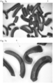
- the Figures 7a to 7c show three photos of abrasive particles 8, whereby the abrasive particles 8 are shown at different levels of magnification.
- the abrasive particles 8 have a cross-sectional shape which is approximately the same as the cross-sectional shape of the Figure 5d
- the abrasive particles 8 have different lengths c.
- the abrasive particles 8 are curved to different degrees in the longitudinal direction 34.
- some abrasive particles 8 are also twisted about their central axis 35 in the longitudinal direction 34. In general, it can be seen that the abrasive particles 8 have a non-uniform shape and size.
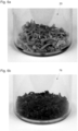
- the Figures 8a and 8b show a grinding tool 36 which was formed from a plurality of the abrasive particles 8 by Abrasive particles 8 have been embedded in a bond, for example in a ceramic bond or in a synthetic resin bond.
- the grinding tool 36 has a porosity of 2 to 50% and/or a density of 1.5 to 4.5 g/cm 3.
- the irregular geometry of the abrasive particles 8 results in a porous structure and an open structure of the grinding tool 36 with excellent grinding performance.
- the grinding tool 36 is particularly suitable for processing metallic materials.
Landscapes
- Chemical & Material Sciences (AREA)
- Engineering & Computer Science (AREA)
- Organic Chemistry (AREA)
- Materials Engineering (AREA)
- Ceramic Engineering (AREA)
- Manufacturing & Machinery (AREA)
- Structural Engineering (AREA)
- Chemical Kinetics & Catalysis (AREA)
- Polishing Bodies And Polishing Tools (AREA)
Claims (14)
- Procédé (1) de fabrication de particules abrasives (3, 4, 5, 6, 7, 8), avec les étapes de procédé suivantes :i. fourniture d'un mélange de départ (9) contenant au moins de l'hydroxyde d'aluminium, lequel peut être converti au moins en oxyde d'aluminium par traitement thermique ;ii. extrusion du mélange de départ (9) en un extrudat (10), de préférence sous la forme d'un boyau (11) avec une section transversale (22) sensiblement circulaire ou d'une bande (21) avec une section transversale (37) sensiblement rectangulaire,iii. découpage de l'extrudat (10) avec des tranchants (13, 14, 15, 16, 17, 18, 19) géométriquement définis, de préférence des râpes, en particules intermédiaires (20) avec une forme et/ou une taille non homogènes,iv. traitement thermique des particules intermédiaires (20), dans lequel les particules intermédiaires sont converties en particules abrasives (3, 4, 5, 6, 7, 8), lesquelles contiennent de l'oxyde d'aluminium, dans lequel les particules abrasives (3, 4, 5, 6, 7, 8) présentent une forme et/ou une taille non homogènes,dans lequel le découpage de l'extrudat (10) est effectué au moyen d'au moins un corps de rotation (23, 24), de préférence sous la forme d'un tambour (23) ou d'un disque (24), dans lequel le corps de rotation (23, 24) fonctionne à une vitesse de rotation (38) modifiable, et/ou au moyen d'un corps en forme de plaque (80), dans lequel les tranchants (13, 14, 15, 16, 17, 18, 19) définis géométriquement sont réalisés sur la surface (25, 26, 81) de l'au moins un corps de rotation (23, 24) ou du corps en forme de plaque (80), de préférence dans lequel les tranchants (13, 14, 15, 16, 17, 18, 19) ont été réalisés par estampage.
- Procédé (1) selon la revendication 1, dans lequel l'au moins un corps de rotation (23, 24) ou le corps en forme de plaque (80) exécute un déplacement oscillant au moins lors du découpage de l'extrudat (10).
- Procédé (1) selon l'une quelconque des revendications 1 ou 2, dans lequel l'extrudat (10) présente une forme de section transversale définie, et la forme de section transversale est modifiée avant le découpage, de préférence au moyen de cylindres (27, 28) tournant en sens inverse.
- Procédé (1) selon l'une quelconque des revendications 1 à 3, dans lequel l'extrudat (10) est amené à l'étape de procédé du découpage avec une vitesse d'approche (29) modifiable et/ou avec un déplacement oscillant.
- Procédé (1) selon l'une quelconque des revendications 1 à 4, dans lequel les particules intermédiaires (20) produites par le découpage sont, dans le cadre du traitement thermique- calcinées, de manière préférée à une température entre 400 °C et 1200 °C, de manière particulièrement préférée à une température entre 800 °C et 1000 °C, et/ou- frittées, de manière préférée à une température entre 1200 °C et 1800 °C, de manière particulièrement préférée à une température entre 1200 °C et 1500 °C.
- Procédé (1) selon la revendication 5, dans lequel les particules intermédiaires (20) produites par le découpage sont séchées au préalable avant la calcination et/ou le frittage dans le cadre du traitement thermique, de manière préférée à une température entre 50 °C et 350 °C, de manière particulièrement préférée à une température entre 80 °C et 100 °C.
- Procédé (1) selon l'une quelconque des revendications 1 à 6, dans lequel les particules intermédiaires (20) produites par le découpage sont fragmentées avant le traitement thermique dans une autre étape de procédé, de préférence au moyen d'un dispositif de découpage (30).
- Procédé (1) selon l'une quelconque des revendications 1 à 7, dans lequel les particules abrasives (3, 4, 5, 6, 7, 8) présentes après le traitement thermique sont refroidies.
- Procédé (1) selon l'une quelconque des revendications 1 à 8, dans lequel de l'eau (31), un agent peptisant, de préférence de l'acide nitrique (32), et/ou des additifs (33), par exemple un acide et/ou du nitrate de cobalt, sont ajoutés lors de la préparation du mélange de départ (9) et/ou lors de l'extrusion du mélange de départ (9).
- Particules abrasives (3, 4, 5, 6, 7, 8) fabriquées selon un procédé (1) selon l'une quelconque des revendications 1 à 9, dans lesquelles les particules abrasives (3, 4, 5, 6, 7, 8) présentent une forme et/ou une taille non homogène.
- Particules abrasives (3, 4, 5, 6, 7, 8) selon la revendication 10, dans lesquelles les particules abrasives (3, 4, 5, 6, 7, 8) sont incurvées dans le sens longitudinal (34) et/ou sont tournées dans le sens longitudinal (34) le long de leur axe central (35).
- Particules abrasives (3, 4, 5, 6, 7, 8) selon la revendication 10 ou 11, dans lesquelles les particules abrasives (3, 4, 5, 6, 7, 8) présentent une largeur a, une hauteur b et une longueur c, la largeur a est supérieure ou égale à la hauteur b, la longueur c est supérieure à la largeur a, et la largeur a est supérieure à 10 µm et est inférieure à 10 mm.
- Procédé de fabrication d'un outil de rectification (36) pour l'usinage de matériaux métalliques, dans lequel des particules abrasives (3, 4, 5, 6, 7, 8), lesquelles ont été fabriquées selon un procédé (1) selon l'une quelconque des revendications 1 à 9, sont incorporées dans un liant, par exemple dans un liant en céramique ou un liant en résine synthétique.
- Outil de rectification (36) fabriqué selon un procédé selon la revendication 13, dans lequel l'outil de rectification (36) présente une porosité de 2 à 50 % et/ou une densité de 1,5 à 4,5 g/cm3.
Applications Claiming Priority (1)
| Application Number | Priority Date | Filing Date | Title |
|---|---|---|---|
| ATA51158/2016A AT519483B1 (de) | 2016-12-20 | 2016-12-20 | Verfahren zur herstellung von schleifmittelteilchen |
Publications (3)
| Publication Number | Publication Date |
|---|---|
| EP3342839A1 EP3342839A1 (fr) | 2018-07-04 |
| EP3342839C0 EP3342839C0 (fr) | 2024-08-21 |
| EP3342839B1 true EP3342839B1 (fr) | 2024-08-21 |
Family
ID=60450490
Family Applications (1)
| Application Number | Title | Priority Date | Filing Date |
|---|---|---|---|
| EP17203051.2A Active EP3342839B1 (fr) | 2016-12-20 | 2017-11-22 | Procédé de fabrication de particules abrasives |
Country Status (2)
| Country | Link |
|---|---|
| EP (1) | EP3342839B1 (fr) |
| AT (1) | AT519483B1 (fr) |
Families Citing this family (26)
| Publication number | Priority date | Publication date | Assignee | Title |
|---|---|---|---|---|
| KR102074138B1 (ko) | 2011-12-30 | 2020-02-07 | 생-고뱅 세라믹스 앤드 플라스틱스, 인코포레이티드 | 형상화 연마입자 및 이의 형성방법 |
| EP3705177A1 (fr) | 2012-01-10 | 2020-09-09 | Saint-Gobain Ceramics & Plastics Inc. | Particules abrasives dotées de formes complexes et méthodes pour former les mêmes |
| KR101736085B1 (ko) | 2012-10-15 | 2017-05-16 | 생-고뱅 어브레이시브즈, 인코포레이티드 | 특정한 형태들을 가진 연마 입자들 및 이러한 입자들을 형성하는 방법들 |
| CN105073343B (zh) | 2013-03-29 | 2017-11-03 | 圣戈班磨料磨具有限公司 | 具有特定形状的磨粒、形成这种粒子的方法及其用途 |
| CN105764653B (zh) | 2013-09-30 | 2020-09-11 | 圣戈本陶瓷及塑料股份有限公司 | 成形磨粒及其形成方法 |
| EP3089851B1 (fr) | 2013-12-31 | 2019-02-06 | Saint-Gobain Abrasives, Inc. | Article abrasif comprenant des particules abrasives façonnées |
| US9771507B2 (en) | 2014-01-31 | 2017-09-26 | Saint-Gobain Ceramics & Plastics, Inc. | Shaped abrasive particle including dopant material and method of forming same |
| MX394114B (es) | 2014-04-14 | 2025-03-24 | Saint Gobain Ceramics | Articulo abrasivo que incluye particulas abrasivas conformadas. |
| US9914864B2 (en) | 2014-12-23 | 2018-03-13 | Saint-Gobain Ceramics & Plastics, Inc. | Shaped abrasive particles and method of forming same |
| TWI634200B (zh) | 2015-03-31 | 2018-09-01 | 聖高拜磨料有限公司 | 固定磨料物品及其形成方法 |
| CN116967949A (zh) | 2015-03-31 | 2023-10-31 | 圣戈班磨料磨具有限公司 | 固定磨料制品和其形成方法 |
| US10711171B2 (en) | 2015-06-11 | 2020-07-14 | Saint-Gobain Ceramics & Plastics, Inc. | Abrasive article including shaped abrasive particles |
| CN121249321A (zh) | 2016-05-10 | 2026-01-02 | 圣戈本陶瓷及塑料股份有限公司 | 磨料颗粒及其形成方法 |
| US11718774B2 (en) | 2016-05-10 | 2023-08-08 | Saint-Gobain Ceramics & Plastics, Inc. | Abrasive particles and methods of forming same |
| US11230653B2 (en) | 2016-09-29 | 2022-01-25 | Saint-Gobain Abrasives, Inc. | Fixed abrasive articles and methods of forming same |
| US10563105B2 (en) | 2017-01-31 | 2020-02-18 | Saint-Gobain Ceramics & Plastics, Inc. | Abrasive article including shaped abrasive particles |
| WO2018236989A1 (fr) | 2017-06-21 | 2018-12-27 | Saint-Gobain Ceramics & Plastics, Inc. | Matériaux particulaires et leurs procédés de formation |
| AT523085B1 (de) | 2019-10-30 | 2022-11-15 | Tyrolit Schleifmittelwerke Swarovski Kg | Verfahren zur Herstellung von Schleifmittelteilchen |
| WO2021133876A1 (fr) | 2019-12-27 | 2021-07-01 | Saint-Gobain Ceramics & Plastics, Inc. | Articles abrasifs et leurs procédés de formation |
| US11926019B2 (en) | 2019-12-27 | 2024-03-12 | Saint-Gobain Ceramics & Plastics, Inc. | Abrasive articles and methods of forming same |
| WO2021133888A1 (fr) | 2019-12-27 | 2021-07-01 | Saint-Gobain Ceramics & Plastics, Inc. | Articles abrasifs et leurs procédés de formation |
| AT523400B1 (de) * | 2020-03-11 | 2021-08-15 | Tyrolit Schleifmittelwerke Swarovski Kg | Verfahren zur Herstellung von Schleifmittelteilchen |
| CN118541241A (zh) | 2021-12-30 | 2024-08-23 | 圣戈班磨料磨具有限公司 | 磨料制品及其形成方法 |
| US12508688B2 (en) | 2021-12-30 | 2025-12-30 | Saint-Gobain Abrasives, Inc. | Abrasive articles and methods of forming same |
| KR20240148817A (ko) | 2021-12-30 | 2024-10-11 | 세인트-고바인 아브라시브즈 인크. | 연마 물품 및 이의 형성 방법 |
| CN117358151A (zh) * | 2023-10-16 | 2024-01-09 | 上海瑞宝造粒机有限公司 | 一种造粒机 |
Family Cites Families (10)
| Publication number | Priority date | Publication date | Assignee | Title |
|---|---|---|---|---|
| JPS5983932A (ja) * | 1982-09-23 | 1984-05-15 | ステンカ−・コ−ポレ−シヨン | 高純度アルミナ粒子の製造法 |
| US5103598A (en) * | 1989-04-28 | 1992-04-14 | Norton Company | Coated abrasive material containing abrasive filaments |
| US6228134B1 (en) * | 1998-04-22 | 2001-05-08 | 3M Innovative Properties Company | Extruded alumina-based abrasive grit, abrasive products, and methods |
| US6053956A (en) * | 1998-05-19 | 2000-04-25 | 3M Innovative Properties Company | Method for making abrasive grain using impregnation and abrasive articles |
| US6277161B1 (en) * | 1999-09-28 | 2001-08-21 | 3M Innovative Properties Company | Abrasive grain, abrasive articles, and methods of making and using the same |
| DE10019184A1 (de) * | 2000-04-17 | 2001-10-25 | Treibacher Schleifmittel Gmbh | Formkörper |
| CN103189164B (zh) * | 2010-11-01 | 2016-07-06 | 3M创新有限公司 | 用于制备成形陶瓷磨粒的激光法、成形陶瓷磨粒以及磨料制品 |
| BR112013016948A2 (pt) * | 2010-12-30 | 2019-09-24 | Saint Gobain Abrasives Inc | método para produzir partículas abrasivas e grãos abrasivos |
| EP3705177A1 (fr) * | 2012-01-10 | 2020-09-09 | Saint-Gobain Ceramics & Plastics Inc. | Particules abrasives dotées de formes complexes et méthodes pour former les mêmes |
| KR102534897B1 (ko) * | 2012-05-23 | 2023-05-30 | 생-고뱅 세라믹스 앤드 플라스틱스, 인코포레이티드 | 형상화 연마입자들 및 이의 형성방법 |
-
2016
- 2016-12-20 AT ATA51158/2016A patent/AT519483B1/de active
-
2017
- 2017-11-22 EP EP17203051.2A patent/EP3342839B1/fr active Active
Also Published As
| Publication number | Publication date |
|---|---|
| EP3342839A1 (fr) | 2018-07-04 |
| AT519483B1 (de) | 2018-12-15 |
| EP3342839C0 (fr) | 2024-08-21 |
| AT519483A1 (de) | 2018-07-15 |
Similar Documents
| Publication | Publication Date | Title |
|---|---|---|
| EP3342839B1 (fr) | Procédé de fabrication de particules abrasives | |
| AT523085B1 (de) | Verfahren zur Herstellung von Schleifmittelteilchen | |
| AT523400B1 (de) | Verfahren zur Herstellung von Schleifmittelteilchen | |
| AT515223B1 (de) | Verfahren zur Herstellung von Schleifmittel | |
| AT515229B1 (de) | Verfahren zur Herstellung von Schleifmittel | |
| EP3083869B1 (fr) | Procédé de production de corps abrasifs | |
| EP2938691B1 (fr) | Grain abrasif avec une section concave | |
| DE3113326C2 (fr) | ||
| WO2015090284A1 (fr) | Procédé de fabrication de particules abrasives multicouches | |
| DE2359367A1 (de) | Verstaerkungsfasern fuer ein vergiessbares einbettungsmaterial, beispielsweise beton und verfahren zur herstellung der verstaerkungsfasern | |
| DE60127305T2 (de) | Verfahren zur herstellung eines schneidwerkzeugs | |
| EP2692816A1 (fr) | Grain abrasif avec corps plats se pénétrant | |
| DE2013198B2 (de) | Verfahren zur Herstellung von diamanthaltigen Körpern | |
| EP2692820A1 (fr) | Grain abrasif avec corps de base, soulèvement et ouverture | |
| DE2167151B1 (de) | Verfahren zum Herstellen eines diamantbestueckten Schneideinsatzes | |
| EP2629917A1 (fr) | Fraise pour dent et procédé de fraisage des dents d'éléments d'engrenage à dents | |
| EP3793728A1 (fr) | Matrice pourvue de parties imprimées avec du métal, servant à l'obtention de corps façonnés par extrusion | |
| EP0209084A1 (fr) | Procédé de préparation d'abrasifs polycristallins céramiques | |
| DE2421311A1 (de) | Keramisches erzeugnis, insbesondere keramisches bauteil und verfahren zur herstellung desselben | |
| EP0597912A1 (fr) | Utilisation d'un dispositif melangeur, granulateur et secheur. | |
| EP1018396B1 (fr) | Procédé de fabrication d' une pièce dentée pour un dispositif de pelletisation d' une matière coulante | |
| DE69804695T2 (de) | Schneideeinsatz für Schleifwerkzeug | |
| DE102016216345B3 (de) | Vorrichtung und Verfahren zur Dissoziation von Gewebe | |
| DE102015216538B3 (de) | Verfahren zum Herstellen eines mehrdimensional skalierbaren Werkzeugs | |
| DE2062126B2 (de) | Kernbrennstoff, welcher Uran und Plutonium enthält |
Legal Events
| Date | Code | Title | Description |
|---|---|---|---|
| PUAI | Public reference made under article 153(3) epc to a published international application that has entered the european phase |
Free format text: ORIGINAL CODE: 0009012 |
|
| STAA | Information on the status of an ep patent application or granted ep patent |
Free format text: STATUS: THE APPLICATION HAS BEEN PUBLISHED |
|
| AK | Designated contracting states |
Kind code of ref document: A1 Designated state(s): AL AT BE BG CH CY CZ DE DK EE ES FI FR GB GR HR HU IE IS IT LI LT LU LV MC MK MT NL NO PL PT RO RS SE SI SK SM TR |
|
| AX | Request for extension of the european patent |
Extension state: BA ME |
|
| STAA | Information on the status of an ep patent application or granted ep patent |
Free format text: STATUS: REQUEST FOR EXAMINATION WAS MADE |
|
| 17P | Request for examination filed |
Effective date: 20180727 |
|
| RBV | Designated contracting states (corrected) |
Designated state(s): AL AT BE BG CH CY CZ DE DK EE ES FI FR GB GR HR HU IE IS IT LI LT LU LV MC MK MT NL NO PL PT RO RS SE SI SK SM TR |
|
| STAA | Information on the status of an ep patent application or granted ep patent |
Free format text: STATUS: EXAMINATION IS IN PROGRESS |
|
| 17Q | First examination report despatched |
Effective date: 20200205 |
|
| GRAP | Despatch of communication of intention to grant a patent |
Free format text: ORIGINAL CODE: EPIDOSNIGR1 |
|
| STAA | Information on the status of an ep patent application or granted ep patent |
Free format text: STATUS: GRANT OF PATENT IS INTENDED |
|
| RIC1 | Information provided on ipc code assigned before grant |
Ipc: C04B 35/111 20060101ALI20240430BHEP Ipc: B01J 2/20 20060101ALI20240430BHEP Ipc: C09K 3/14 20060101AFI20240430BHEP |
|
| INTG | Intention to grant announced |
Effective date: 20240515 |
|
| GRAS | Grant fee paid |
Free format text: ORIGINAL CODE: EPIDOSNIGR3 |
|
| GRAA | (expected) grant |
Free format text: ORIGINAL CODE: 0009210 |
|
| STAA | Information on the status of an ep patent application or granted ep patent |
Free format text: STATUS: THE PATENT HAS BEEN GRANTED |
|
| AK | Designated contracting states |
Kind code of ref document: B1 Designated state(s): AL AT BE BG CH CY CZ DE DK EE ES FI FR GB GR HR HU IE IS IT LI LT LU LV MC MK MT NL NO PL PT RO RS SE SI SK SM TR |
|
| RAP3 | Party data changed (applicant data changed or rights of an application transferred) |
Owner name: TYROLIT - SCHLEIFMITTELWERKESWAROVSKI AG & CO K.G. |
|
| REG | Reference to a national code |
Ref country code: GB Ref legal event code: FG4D Free format text: NOT ENGLISH |
|
| REG | Reference to a national code |
Ref country code: CH Ref legal event code: EP |
|
| REG | Reference to a national code |
Ref country code: IE Ref legal event code: FG4D Free format text: LANGUAGE OF EP DOCUMENT: GERMAN |
|
| REG | Reference to a national code |
Ref country code: DE Ref legal event code: R096 Ref document number: 502017016359 Country of ref document: DE |
|
| U01 | Request for unitary effect filed |
Effective date: 20240919 |
|
| U07 | Unitary effect registered |
Designated state(s): AT BE BG DE DK EE FI FR IT LT LU LV MT NL PT RO SE SI Effective date: 20241008 |
|
| U20 | Renewal fee for the european patent with unitary effect paid |
Year of fee payment: 8 Effective date: 20241120 |
|
| PG25 | Lapsed in a contracting state [announced via postgrant information from national office to epo] |
Ref country code: NO Free format text: LAPSE BECAUSE OF FAILURE TO SUBMIT A TRANSLATION OF THE DESCRIPTION OR TO PAY THE FEE WITHIN THE PRESCRIBED TIME-LIMIT Effective date: 20241121 |
|
| PG25 | Lapsed in a contracting state [announced via postgrant information from national office to epo] |
Ref country code: GR Free format text: LAPSE BECAUSE OF FAILURE TO SUBMIT A TRANSLATION OF THE DESCRIPTION OR TO PAY THE FEE WITHIN THE PRESCRIBED TIME-LIMIT Effective date: 20241122 Ref country code: PL Free format text: LAPSE BECAUSE OF FAILURE TO SUBMIT A TRANSLATION OF THE DESCRIPTION OR TO PAY THE FEE WITHIN THE PRESCRIBED TIME-LIMIT Effective date: 20240821 |
|
| PG25 | Lapsed in a contracting state [announced via postgrant information from national office to epo] |
Ref country code: IS Free format text: LAPSE BECAUSE OF FAILURE TO SUBMIT A TRANSLATION OF THE DESCRIPTION OR TO PAY THE FEE WITHIN THE PRESCRIBED TIME-LIMIT Effective date: 20241221 |
|
| PG25 | Lapsed in a contracting state [announced via postgrant information from national office to epo] |
Ref country code: HR Free format text: LAPSE BECAUSE OF FAILURE TO SUBMIT A TRANSLATION OF THE DESCRIPTION OR TO PAY THE FEE WITHIN THE PRESCRIBED TIME-LIMIT Effective date: 20240821 |
|
| PG25 | Lapsed in a contracting state [announced via postgrant information from national office to epo] |
Ref country code: ES Free format text: LAPSE BECAUSE OF FAILURE TO SUBMIT A TRANSLATION OF THE DESCRIPTION OR TO PAY THE FEE WITHIN THE PRESCRIBED TIME-LIMIT Effective date: 20240821 Ref country code: RS Free format text: LAPSE BECAUSE OF FAILURE TO SUBMIT A TRANSLATION OF THE DESCRIPTION OR TO PAY THE FEE WITHIN THE PRESCRIBED TIME-LIMIT Effective date: 20241121 |
|
| PG25 | Lapsed in a contracting state [announced via postgrant information from national office to epo] |
Ref country code: RS Free format text: LAPSE BECAUSE OF FAILURE TO SUBMIT A TRANSLATION OF THE DESCRIPTION OR TO PAY THE FEE WITHIN THE PRESCRIBED TIME-LIMIT Effective date: 20241121 Ref country code: PL Free format text: LAPSE BECAUSE OF FAILURE TO SUBMIT A TRANSLATION OF THE DESCRIPTION OR TO PAY THE FEE WITHIN THE PRESCRIBED TIME-LIMIT Effective date: 20240821 Ref country code: NO Free format text: LAPSE BECAUSE OF FAILURE TO SUBMIT A TRANSLATION OF THE DESCRIPTION OR TO PAY THE FEE WITHIN THE PRESCRIBED TIME-LIMIT Effective date: 20241121 Ref country code: IS Free format text: LAPSE BECAUSE OF FAILURE TO SUBMIT A TRANSLATION OF THE DESCRIPTION OR TO PAY THE FEE WITHIN THE PRESCRIBED TIME-LIMIT Effective date: 20241221 Ref country code: HR Free format text: LAPSE BECAUSE OF FAILURE TO SUBMIT A TRANSLATION OF THE DESCRIPTION OR TO PAY THE FEE WITHIN THE PRESCRIBED TIME-LIMIT Effective date: 20240821 Ref country code: GR Free format text: LAPSE BECAUSE OF FAILURE TO SUBMIT A TRANSLATION OF THE DESCRIPTION OR TO PAY THE FEE WITHIN THE PRESCRIBED TIME-LIMIT Effective date: 20241122 Ref country code: ES Free format text: LAPSE BECAUSE OF FAILURE TO SUBMIT A TRANSLATION OF THE DESCRIPTION OR TO PAY THE FEE WITHIN THE PRESCRIBED TIME-LIMIT Effective date: 20240821 |
|
| PG25 | Lapsed in a contracting state [announced via postgrant information from national office to epo] |
Ref country code: SM Free format text: LAPSE BECAUSE OF FAILURE TO SUBMIT A TRANSLATION OF THE DESCRIPTION OR TO PAY THE FEE WITHIN THE PRESCRIBED TIME-LIMIT Effective date: 20240821 |
|
| PG25 | Lapsed in a contracting state [announced via postgrant information from national office to epo] |
Ref country code: CZ Free format text: LAPSE BECAUSE OF FAILURE TO SUBMIT A TRANSLATION OF THE DESCRIPTION OR TO PAY THE FEE WITHIN THE PRESCRIBED TIME-LIMIT Effective date: 20240821 |
|
| PG25 | Lapsed in a contracting state [announced via postgrant information from national office to epo] |
Ref country code: SK Free format text: LAPSE BECAUSE OF FAILURE TO SUBMIT A TRANSLATION OF THE DESCRIPTION OR TO PAY THE FEE WITHIN THE PRESCRIBED TIME-LIMIT Effective date: 20240821 |
|
| PLBE | No opposition filed within time limit |
Free format text: ORIGINAL CODE: 0009261 |
|
| STAA | Information on the status of an ep patent application or granted ep patent |
Free format text: STATUS: NO OPPOSITION FILED WITHIN TIME LIMIT |
|
| REG | Reference to a national code |
Ref country code: CH Ref legal event code: PL |
|
| PG25 | Lapsed in a contracting state [announced via postgrant information from national office to epo] |
Ref country code: MC Free format text: LAPSE BECAUSE OF FAILURE TO SUBMIT A TRANSLATION OF THE DESCRIPTION OR TO PAY THE FEE WITHIN THE PRESCRIBED TIME-LIMIT Effective date: 20240821 |
|
| REG | Reference to a national code |
Ref country code: CH Ref legal event code: PL |
|
| GBPC | Gb: european patent ceased through non-payment of renewal fee |
Effective date: 20241122 |
|
| PG25 | Lapsed in a contracting state [announced via postgrant information from national office to epo] |
Ref country code: CH Free format text: LAPSE BECAUSE OF NON-PAYMENT OF DUE FEES Effective date: 20241130 |
|
| 26N | No opposition filed |
Effective date: 20250522 |
|
| PG25 | Lapsed in a contracting state [announced via postgrant information from national office to epo] |
Ref country code: GB Free format text: LAPSE BECAUSE OF NON-PAYMENT OF DUE FEES Effective date: 20241122 |
|
| PG25 | Lapsed in a contracting state [announced via postgrant information from national office to epo] |
Ref country code: IE Free format text: LAPSE BECAUSE OF NON-PAYMENT OF DUE FEES Effective date: 20241122 |
|
| U20 | Renewal fee for the european patent with unitary effect paid |
Year of fee payment: 9 Effective date: 20251126 |
|
| PG25 | Lapsed in a contracting state [announced via postgrant information from national office to epo] |
Ref country code: HU Free format text: LAPSE BECAUSE OF FAILURE TO SUBMIT A TRANSLATION OF THE DESCRIPTION OR TO PAY THE FEE WITHIN THE PRESCRIBED TIME-LIMIT; INVALID AB INITIO Effective date: 20171122 |
|
| PG25 | Lapsed in a contracting state [announced via postgrant information from national office to epo] |
Ref country code: CY Free format text: LAPSE BECAUSE OF FAILURE TO SUBMIT A TRANSLATION OF THE DESCRIPTION OR TO PAY THE FEE WITHIN THE PRESCRIBED TIME-LIMIT; INVALID AB INITIO Effective date: 20171122 |