EP3343018A1 - Système pour démarrer un moteur - Google Patents
Système pour démarrer un moteur Download PDFInfo
- Publication number
- EP3343018A1 EP3343018A1 EP17205957.8A EP17205957A EP3343018A1 EP 3343018 A1 EP3343018 A1 EP 3343018A1 EP 17205957 A EP17205957 A EP 17205957A EP 3343018 A1 EP3343018 A1 EP 3343018A1
- Authority
- EP
- European Patent Office
- Prior art keywords
- controller
- angle sensor
- angle
- state
- logic
- Prior art date
- Legal status (The legal status is an assumption and is not a legal conclusion. Google has not performed a legal analysis and makes no representation as to the accuracy of the status listed.)
- Withdrawn
Links
Images



Classifications
-
- F—MECHANICAL ENGINEERING; LIGHTING; HEATING; WEAPONS; BLASTING
- F02—COMBUSTION ENGINES; HOT-GAS OR COMBUSTION-PRODUCT ENGINE PLANTS
- F02N—STARTING OF COMBUSTION ENGINES; STARTING AIDS FOR SUCH ENGINES, NOT OTHERWISE PROVIDED FOR
- F02N11/00—Starting of engines by means of electric motors
- F02N11/10—Safety devices
- F02N11/101—Safety devices for preventing engine starter actuation or engagement
- F02N11/103—Safety devices for preventing engine starter actuation or engagement according to the vehicle transmission or clutch status
-
- F—MECHANICAL ENGINEERING; LIGHTING; HEATING; WEAPONS; BLASTING
- F02—COMBUSTION ENGINES; HOT-GAS OR COMBUSTION-PRODUCT ENGINE PLANTS
- F02N—STARTING OF COMBUSTION ENGINES; STARTING AIDS FOR SUCH ENGINES, NOT OTHERWISE PROVIDED FOR
- F02N11/00—Starting of engines by means of electric motors
- F02N11/08—Circuits specially adapted for starting of engines
-
- F—MECHANICAL ENGINEERING; LIGHTING; HEATING; WEAPONS; BLASTING
- F02—COMBUSTION ENGINES; HOT-GAS OR COMBUSTION-PRODUCT ENGINE PLANTS
- F02N—STARTING OF COMBUSTION ENGINES; STARTING AIDS FOR SUCH ENGINES, NOT OTHERWISE PROVIDED FOR
- F02N11/00—Starting of engines by means of electric motors
- F02N11/08—Circuits specially adapted for starting of engines
- F02N11/0851—Circuits specially adapted for starting of engines characterised by means for controlling the engagement or disengagement between engine and starter, e.g. meshing of pinion and engine gear
-
- F—MECHANICAL ENGINEERING; LIGHTING; HEATING; WEAPONS; BLASTING
- F02—COMBUSTION ENGINES; HOT-GAS OR COMBUSTION-PRODUCT ENGINE PLANTS
- F02N—STARTING OF COMBUSTION ENGINES; STARTING AIDS FOR SUCH ENGINES, NOT OTHERWISE PROVIDED FOR
- F02N11/00—Starting of engines by means of electric motors
- F02N11/08—Circuits specially adapted for starting of engines
- F02N11/087—Details of the switching means in starting circuits, e.g. relays or electronic switches
-
- F—MECHANICAL ENGINEERING; LIGHTING; HEATING; WEAPONS; BLASTING
- F16—ENGINEERING ELEMENTS AND UNITS; GENERAL MEASURES FOR PRODUCING AND MAINTAINING EFFECTIVE FUNCTIONING OF MACHINES OR INSTALLATIONS; THERMAL INSULATION IN GENERAL
- F16H—GEARING
- F16H59/00—Control inputs to control units of change-speed- or reversing-gearings for conveying rotary motion
- F16H59/02—Selector apparatus
- F16H59/08—Range selector apparatus
- F16H59/10—Range selector apparatus comprising levers
- F16H59/105—Range selector apparatus comprising levers consisting of electrical switches or sensors
-
- F—MECHANICAL ENGINEERING; LIGHTING; HEATING; WEAPONS; BLASTING
- F16—ENGINEERING ELEMENTS AND UNITS; GENERAL MEASURES FOR PRODUCING AND MAINTAINING EFFECTIVE FUNCTIONING OF MACHINES OR INSTALLATIONS; THERMAL INSULATION IN GENERAL
- F16H—GEARING
- F16H61/00—Control functions within control units of change-speed- or reversing-gearings for conveying rotary motion ; Control of exclusively fluid gearing, friction gearing, gearings with endless flexible members or other particular types of gearing
- F16H61/12—Detecting malfunction or potential malfunction, e.g. fail safe ; Circumventing or fixing failures
-
- G—PHYSICS
- G01—MEASURING; TESTING
- G01D—MEASURING NOT SPECIALLY ADAPTED FOR A SPECIFIC VARIABLE; ARRANGEMENTS FOR MEASURING TWO OR MORE VARIABLES NOT COVERED IN A SINGLE OTHER SUBCLASS; TARIFF METERING APPARATUS; MEASURING OR TESTING NOT OTHERWISE PROVIDED FOR
- G01D5/00—Mechanical means for transferring the output of a sensing member; Means for converting the output of a sensing member to another variable where the form or nature of the sensing member does not constrain the means for converting; Transducers not specially adapted for a specific variable
- G01D5/12—Mechanical means for transferring the output of a sensing member; Means for converting the output of a sensing member to another variable where the form or nature of the sensing member does not constrain the means for converting; Transducers not specially adapted for a specific variable using electric or magnetic means
- G01D5/14—Mechanical means for transferring the output of a sensing member; Means for converting the output of a sensing member to another variable where the form or nature of the sensing member does not constrain the means for converting; Transducers not specially adapted for a specific variable using electric or magnetic means influencing the magnitude of a current or voltage
- G01D5/142—Mechanical means for transferring the output of a sensing member; Means for converting the output of a sensing member to another variable where the form or nature of the sensing member does not constrain the means for converting; Transducers not specially adapted for a specific variable using electric or magnetic means influencing the magnitude of a current or voltage using Hall-effect devices
- G01D5/145—Mechanical means for transferring the output of a sensing member; Means for converting the output of a sensing member to another variable where the form or nature of the sensing member does not constrain the means for converting; Transducers not specially adapted for a specific variable using electric or magnetic means influencing the magnitude of a current or voltage using Hall-effect devices influenced by the relative movement between the Hall device and magnetic fields
-
- F—MECHANICAL ENGINEERING; LIGHTING; HEATING; WEAPONS; BLASTING
- F02—COMBUSTION ENGINES; HOT-GAS OR COMBUSTION-PRODUCT ENGINE PLANTS
- F02D—CONTROLLING COMBUSTION ENGINES
- F02D2200/00—Input parameters for engine control
- F02D2200/50—Input parameters for engine control said parameters being related to the vehicle or its components
- F02D2200/502—Neutral gear position
-
- F—MECHANICAL ENGINEERING; LIGHTING; HEATING; WEAPONS; BLASTING
- F02—COMBUSTION ENGINES; HOT-GAS OR COMBUSTION-PRODUCT ENGINE PLANTS
- F02D—CONTROLLING COMBUSTION ENGINES
- F02D41/00—Electrical control of supply of combustible mixture or its constituents
- F02D41/009—Electrical control of supply of combustible mixture or its constituents using means for generating position or synchronisation signals
-
- F—MECHANICAL ENGINEERING; LIGHTING; HEATING; WEAPONS; BLASTING
- F02—COMBUSTION ENGINES; HOT-GAS OR COMBUSTION-PRODUCT ENGINE PLANTS
- F02N—STARTING OF COMBUSTION ENGINES; STARTING AIDS FOR SUCH ENGINES, NOT OTHERWISE PROVIDED FOR
- F02N2200/00—Parameters used for control of starting apparatus
- F02N2200/02—Parameters used for control of starting apparatus said parameters being related to the engine
- F02N2200/021—Engine crank angle
-
- F—MECHANICAL ENGINEERING; LIGHTING; HEATING; WEAPONS; BLASTING
- F02—COMBUSTION ENGINES; HOT-GAS OR COMBUSTION-PRODUCT ENGINE PLANTS
- F02N—STARTING OF COMBUSTION ENGINES; STARTING AIDS FOR SUCH ENGINES, NOT OTHERWISE PROVIDED FOR
- F02N2200/00—Parameters used for control of starting apparatus
- F02N2200/08—Parameters used for control of starting apparatus said parameters being related to the vehicle or its components
- F02N2200/0802—Transmission state, e.g. gear ratio or neutral state
-
- F—MECHANICAL ENGINEERING; LIGHTING; HEATING; WEAPONS; BLASTING
- F02—COMBUSTION ENGINES; HOT-GAS OR COMBUSTION-PRODUCT ENGINE PLANTS
- F02N—STARTING OF COMBUSTION ENGINES; STARTING AIDS FOR SUCH ENGINES, NOT OTHERWISE PROVIDED FOR
- F02N2200/00—Parameters used for control of starting apparatus
- F02N2200/08—Parameters used for control of starting apparatus said parameters being related to the vehicle or its components
- F02N2200/0803—Parking brake state
-
- F—MECHANICAL ENGINEERING; LIGHTING; HEATING; WEAPONS; BLASTING
- F16—ENGINEERING ELEMENTS AND UNITS; GENERAL MEASURES FOR PRODUCING AND MAINTAINING EFFECTIVE FUNCTIONING OF MACHINES OR INSTALLATIONS; THERMAL INSULATION IN GENERAL
- F16H—GEARING
- F16H59/00—Control inputs to control units of change-speed- or reversing-gearings for conveying rotary motion
- F16H59/36—Inputs being a function of speed
- F16H59/44—Inputs being a function of speed dependent on machine speed, e.g. the vehicle speed
- F16H2059/446—Detecting vehicle stop, i.e. the vehicle is at stand still, e.g. for engaging parking lock
-
- F—MECHANICAL ENGINEERING; LIGHTING; HEATING; WEAPONS; BLASTING
- F16—ENGINEERING ELEMENTS AND UNITS; GENERAL MEASURES FOR PRODUCING AND MAINTAINING EFFECTIVE FUNCTIONING OF MACHINES OR INSTALLATIONS; THERMAL INSULATION IN GENERAL
- F16H—GEARING
- F16H59/00—Control inputs to control units of change-speed- or reversing-gearings for conveying rotary motion
- F16H59/68—Inputs being a function of gearing status
- F16H2059/6823—Sensing neutral state of the transmission
-
- F—MECHANICAL ENGINEERING; LIGHTING; HEATING; WEAPONS; BLASTING
- F16—ENGINEERING ELEMENTS AND UNITS; GENERAL MEASURES FOR PRODUCING AND MAINTAINING EFFECTIVE FUNCTIONING OF MACHINES OR INSTALLATIONS; THERMAL INSULATION IN GENERAL
- F16H—GEARING
- F16H61/00—Control functions within control units of change-speed- or reversing-gearings for conveying rotary motion ; Control of exclusively fluid gearing, friction gearing, gearings with endless flexible members or other particular types of gearing
- F16H61/22—Locking of the control input devices
- F16H2061/223—Electrical gear shift lock, e.g. locking of lever in park or neutral position by electric means if brake is not applied; Key interlock, i.e. locking the key if lever is not in park position
Definitions
- the present invention relates to a system to safely crank an automatic or robotic transmission vehicle engine.
- the system includes an ECU controller 30, such like a PEPS or EMS ECU, a cranking relay 10 enabling the engine to be cranked and an inhibitor switch 20.
- the inhibitor switch may also be called Neutral or Park SW (in short PN switch).
- the inhibitor switch is, in this case, an electromechanical switch assembled directly on or sometimes into the transmission.
- the inhibitor switch is mechanically coding the transmission gear state in such a way it is in a closed position when the transmission is in the Neutral or Park gear state.
- the inhibitor switch 20 When the transmission is in the Neutral or Park state, the inhibitor switch 20 is closed, pulling the ECU 30 feedback input terminal and the cranking relay coil 10 to the ground level and electrically enabling the cranking relay 10 actuation. Should a vehicle cranking be required, the controller ECU 30 is checking the inhibitor switch 20 state and, if detect closed (in Neutral or Park state), is actuating the High side switch terminal, powering the cranking relay 10, finally resulting in cranking the vehicle engine.
- cranking relay 20 can't be electrically actuated. This configuration realizes a logical AND requirement satisfying the ISO 26262 ASIL B level.
- the safety condition can be met by reversing the logic (e.g. powering one cranking relay 20 terminal and actuating it with a Low Side switch). This configuration would also satisfy the ISO26262 ASIL B level.
- the electromechanical inhibitor switch being subjected to mechanical wear out leads in some extreme cases to a functional failure (lost of the cranking ability).
- This type of contactless sensor mostly uses Hall sensors measuring an angle and outputting that angle rather than a gear box state and, consequently, making it is impossible to immediately replace the electromechanical switch by a contactless component.
- the present invention is aimed to propose an angle sensor construction that can be embedded in the ISO26262 ASIL B compliant current architecture defined for electromechanical switches, and an object of the present invention is to build a compact, reliable, small volume and cost-efficient system for cranking an engine in a vehicle.
- a system for enabling an engine to be safely cranked comprises:
- the problem integrating contactless sensors in existing architectures is solved.
- the structure of the whole solution remains unchanged, the volume of the whole system can be compact, and the reliability can be improved.
- FIG. 2 is a circuit diagram showing structure of a system to crank an engine according to the first embodiment of the present invention.
- the system includes a single cranking relay 10 for enabling the engine to be cranked, an angle sensor 20 to detect a gear state and outputting a data signal indicative of that gear state; and an ECU controller 30 to capture the angle sensor signal and control the cranking relay 10.
- the ECU controller 30 may be an EMS or a PEPS ECU, but a separate controller or another existing ECU in the vehicle could also be used.
- cranking relay 10 output is used to crank the engine by closing the relay circuit to the power supply.
- the angle sensor 20 has a first switch output terminal 201 connected to one of the terminal of the cranking relay control coil and also to a terminal of the ECU controller 30, e.g. a Feedback terminal (FB), and the second output terminal 202 connected to the ground (GND).
- the other terminal of the cranking relay 10 control coil is connected to another terminal of the ECU controller 30, e.g. a High Side switch.
- the angle sensor 20 is a single chip sensor including dual sensing units and a logic output switch 26.
- the two sensing units are angle sensors, e.g. magnetic sensors for sensing an angle by Hall Effect in contactless manner.
- the present invention is not limited to:
- the two sensing units are capturing the rotation angle position of the transmission shaft, and acquire, that way, its gear state.
- Each sensing unit is outputting a digital or analog signal carrying the angle information.
- one of the sensing unit outputs is an analog signal and the other one a PWM type signal.
- the logic output switch be activated, that is the logic output switch be "closed”.
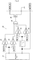
- the computation logic in the above example, is shown in Fig. 3 .
- the analog signal output from the first sensing unit is wired to two comparators 21 and 22 to compare it with an upper and lower limit corresponding to the Neutral or Park gear state angle range.
- the first comparator 21 will output a logic "1"
- the second comparator 22 will output a logic "1" that is to say, if the analog signal is within the range between the upper limit and the lower limit, the comparison result is to be a logic "1", meaning that the shaft angle position is within a predetermined rotation angle range corresponding to the Neutral gear or the Park gear.
- the low pass filtered PWM signal output from the second sensor unit is compared to an upper and a lower limit by using two comparators 23 and 24. If the low pass filtered PWM signal is lower than the upper limit and higher than the lower limit, a logic "1" is output.
- While the logic output switch 26 is activated, it will pull the FB ECU controller terminal input down to GND and, at the same time, it will connect the cranking relay 10 control coil to GND, thus, enabling its activation.
- the logic output switch can be implemented by a transistor, such as a power transistor.
- the ECU controller 30 will control its High Side Switch output, powering the cranking relay coil.
- the cranking relay coil being enable by the angle sensor switched, the cranking relay is switched to "closed", resulting in the engine crank.
- the conventional electromechanical inhibitor switch can be substituted by the angle sensor build according to the FIG. 3 hardware construction. Since the angle sensor integrates two independent sensing units and the hardware needed to compute a logic state output corresponding the Neutral or Park transmission state, the conventional system structure for connecting the inhibitor switch is hardly amended. Migration costs from the electromechanical Inhibitor SW to the contactless pendant are consequently reduced with no additional hardware needed external the contactless inhibitor SW. With the present contactless inhibitor switch, realizing the same function like the conventional electromechanical inhibitor switch, ISO26262 ASIL requirements are satisfied the same way.
- the present invention's angle is implemented using hardware, making it robust and reliable in the high temperature environment it is purposed to operate.
- the 2 sensing units and the relevant computation hardware can be integrated, if wished, into a single chip.
- the hardware nature of the invention avoids problems related to embedding a software solution in a high temperature environment.
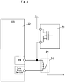
- the angle sensor is connected between the cranking relay and the ground. It would also be possible to connect the angle sensor between the Power Supply and the cranking Relay using a reversed logic. As shown in FIG. 4 , the angle sensor 20 is connected between a Power Supply and one terminal of the cranking relay control coil. In this situation, when the logic output switch of the angle sensor is "closed", the ECU controller 30 will detect the high level rather than the ground, meantime, the power supply is supplied to the terminal of the cranking relay control coil, and in response to the high level being detected by the Feedback terminal of the ECU controller, the ECU controller can activates the relay through a Low side switch. Since the remaining part of the variation is same as that in the first embodiment, it will not be described in additional details.
- the second embodiment is different from the first embodiment as above described mainly in that an angle output signal is additionally output from a third terminal 203 of the angle sensor and is received by the ECU controller.
- the remaining of the second embodiment is the same as that in the first embodiment, and thus will not be further described in detail.
- the angle sensor in addition to the output of the logic output switch 26, the angle sensor further includes a third output terminal 203 to output a signal indicative of the angle position of the transmission shaft.
- the additional signal can be one of the signals output from the two sensor units, for example, in this embodiment, it is the PWM output signal.
- the controller 30 will receive the PWM output signal from the third output terminal 203, and determine the transmission gear state from that PWM output signal. At the same time, the controller 30 will also acquire the state of the logic output switch 26, and only when both the PWM output signal and the output of the logic output switch indicate that the transmission is at the Neutral or Park gear, can the High Side Switch of the controller be activated. As above described with reference to FIG.
- the cranking relay 10 actuation coil is powered, closing the cranking relay and finally resulting in cranking the engine.
- the controller ECU 30 is realizing an additional level of comparison between the signals outputted by the inhibitor switch resulting in a higher level of confidence in the angle value integrity since it provides an additional way to diagnose the switch 26.
Landscapes
- Engineering & Computer Science (AREA)
- General Engineering & Computer Science (AREA)
- Mechanical Engineering (AREA)
- Chemical & Material Sciences (AREA)
- Combustion & Propulsion (AREA)
- Physics & Mathematics (AREA)
- General Physics & Mathematics (AREA)
- Combined Controls Of Internal Combustion Engines (AREA)
- Control Of Vehicle Engines Or Engines For Specific Uses (AREA)
- Arrangement And Mounting Of Devices That Control Transmission Of Motive Force (AREA)
Applications Claiming Priority (1)
| Application Number | Priority Date | Filing Date | Title |
|---|---|---|---|
| CN201611233462.3A CN108252837A (zh) | 2016-12-28 | 2016-12-28 | 起动发动机的系统 |
Publications (1)
| Publication Number | Publication Date |
|---|---|
| EP3343018A1 true EP3343018A1 (fr) | 2018-07-04 |
Family
ID=60654730
Family Applications (1)
| Application Number | Title | Priority Date | Filing Date |
|---|---|---|---|
| EP17205957.8A Withdrawn EP3343018A1 (fr) | 2016-12-28 | 2017-12-07 | Système pour démarrer un moteur |
Country Status (5)
| Country | Link |
|---|---|
| US (1) | US10267284B2 (fr) |
| EP (1) | EP3343018A1 (fr) |
| JP (1) | JP2018109405A (fr) |
| KR (1) | KR20180077084A (fr) |
| CN (1) | CN108252837A (fr) |
Families Citing this family (2)
| Publication number | Priority date | Publication date | Assignee | Title |
|---|---|---|---|---|
| JP7074004B2 (ja) * | 2018-09-25 | 2022-05-24 | 株式会社オートネットワーク技術研究所 | 中継装置システム及び中継装置 |
| CN115384424A (zh) * | 2022-09-05 | 2022-11-25 | 上海三一重机股份有限公司 | 启动控制方法、系统及作业机械 |
Citations (6)
| Publication number | Priority date | Publication date | Assignee | Title |
|---|---|---|---|---|
| US4262526A (en) * | 1978-07-21 | 1981-04-21 | Nippondenso Co., Ltd. | Rotational position detecting apparatus |
| US4485694A (en) * | 1981-01-16 | 1984-12-04 | Nissan Motor Company, Limited | Engine starter circuit for automotive vehicle with automatic transmission |
| DE19602302A1 (de) * | 1995-09-13 | 1997-03-20 | Mitsubishi Electric Corp | Eingriffsentscheidungssystem für Automatikgetriebe |
| WO2009035423A1 (fr) * | 2007-09-13 | 2009-03-19 | Temsa Sanayi Ve Ticaret A.S. | Désactivation du moteur lorsqu'une vitesse est engagée |
| EP1471290B1 (fr) | 2003-04-23 | 2011-03-09 | Aisin Aw Co., Ltd. | Dispositif de détection de défaillance pour un capteur d'angle de rotation |
| CN202481012U (zh) * | 2012-02-28 | 2012-10-10 | 浙江吉利汽车研究院有限公司 | 一种自动挡车辆外围起动装置 |
Family Cites Families (11)
| Publication number | Priority date | Publication date | Assignee | Title |
|---|---|---|---|---|
| IT1251752B (it) * | 1991-10-31 | 1995-05-23 | Fiat Auto Spa | Dispositivo elettronico per la selezione delle marce in un cambio automatico per autoveicoli |
| CA2130637A1 (fr) * | 1993-09-30 | 1995-03-31 | Stephen W. Rector | Mecanisme de commande pour transmission muni de detecteurs sans contact |
| JP3906948B2 (ja) * | 1997-09-13 | 2007-04-18 | 本田技研工業株式会社 | 電動式変速装置の変速制御装置 |
| EP1036928B1 (fr) * | 1999-03-18 | 2007-05-16 | Mitsubishi Jidosha Kogyo Kabushiki Kaisha | Dispositif et méthode de démarrage pour moteur à combustion interne à injection directe |
| JP3972613B2 (ja) * | 2000-09-26 | 2007-09-05 | アイシン・エィ・ダブリュ株式会社 | 原動機始動用制御装置 |
| US20030159534A1 (en) * | 2002-02-22 | 2003-08-28 | American Electronic Components | Transmission shift position sensor |
| US20040178050A1 (en) * | 2002-11-06 | 2004-09-16 | Jonathan Wylde | Neutral sensing switch for remote vehicle starter |
| JP2006046451A (ja) * | 2004-08-03 | 2006-02-16 | Denso Corp | 自動変速機の制御装置 |
| KR100717307B1 (ko) * | 2005-12-09 | 2007-05-15 | 현대자동차주식회사 | 자동변속기 차량에서 시동 모터 제어장치 |
| JP4781228B2 (ja) * | 2006-10-27 | 2011-09-28 | ヤマハ発動機株式会社 | 変速制御装置および車両 |
| JP5997199B2 (ja) * | 2014-03-31 | 2016-09-28 | 本田技研工業株式会社 | 電気供給装置および車両 |
-
2016
- 2016-12-28 CN CN201611233462.3A patent/CN108252837A/zh active Pending
-
2017
- 2017-12-07 EP EP17205957.8A patent/EP3343018A1/fr not_active Withdrawn
- 2017-12-27 KR KR1020170181212A patent/KR20180077084A/ko not_active Withdrawn
- 2017-12-27 US US15/855,998 patent/US10267284B2/en not_active Expired - Fee Related
- 2017-12-27 JP JP2017250386A patent/JP2018109405A/ja active Pending
Patent Citations (6)
| Publication number | Priority date | Publication date | Assignee | Title |
|---|---|---|---|---|
| US4262526A (en) * | 1978-07-21 | 1981-04-21 | Nippondenso Co., Ltd. | Rotational position detecting apparatus |
| US4485694A (en) * | 1981-01-16 | 1984-12-04 | Nissan Motor Company, Limited | Engine starter circuit for automotive vehicle with automatic transmission |
| DE19602302A1 (de) * | 1995-09-13 | 1997-03-20 | Mitsubishi Electric Corp | Eingriffsentscheidungssystem für Automatikgetriebe |
| EP1471290B1 (fr) | 2003-04-23 | 2011-03-09 | Aisin Aw Co., Ltd. | Dispositif de détection de défaillance pour un capteur d'angle de rotation |
| WO2009035423A1 (fr) * | 2007-09-13 | 2009-03-19 | Temsa Sanayi Ve Ticaret A.S. | Désactivation du moteur lorsqu'une vitesse est engagée |
| CN202481012U (zh) * | 2012-02-28 | 2012-10-10 | 浙江吉利汽车研究院有限公司 | 一种自动挡车辆外围起动装置 |
Also Published As
| Publication number | Publication date |
|---|---|
| US20180187643A1 (en) | 2018-07-05 |
| US10267284B2 (en) | 2019-04-23 |
| CN108252837A (zh) | 2018-07-06 |
| KR20180077084A (ko) | 2018-07-06 |
| JP2018109405A (ja) | 2018-07-12 |
Similar Documents
| Publication | Publication Date | Title |
|---|---|---|
| JP4245081B1 (ja) | センサ装置 | |
| US8213869B2 (en) | Interference filtration device adapted to a sensor sensitive to electromagnetic waves and related filtration method | |
| US20150210289A1 (en) | Method for monitoring a door contact switch of a driver' s door of a motor vehicle | |
| US10267284B2 (en) | System to crank an engine | |
| CN111788417B (zh) | 用于确定汽车驻车锁状态的方法 | |
| KR20150142697A (ko) | 안전 스위치 장치들의 직렬 연결을 구비한 안전 체인을 가진 엘리베이터 | |
| JP2015115692A (ja) | 半導体異常検出回路 | |
| CN101799481B (zh) | 传感器装置 | |
| US9353717B2 (en) | Engine control unit for driving an electric circuit and method | |
| KR20140089022A (ko) | 자동차 급발진 및 주행 상태 통합 관리 블랙박스 시스템 | |
| US9129067B2 (en) | Position detector | |
| KR101806364B1 (ko) | 인덕티브 크랭크 센서 고장진단 방법 | |
| JP4358301B1 (ja) | センサ装置 | |
| US12451828B2 (en) | Motor position detection device | |
| CN111149088B (zh) | 用于运行控制器的方法以及具有对应的控制器的设备 | |
| US10340911B2 (en) | Method for programming a two-wire sensor and programmable two-wire sensor | |
| AU2011310191B8 (en) | Slide door current-carrying system | |
| US9739649B2 (en) | Method for increasing the reliability of transducers | |
| US11905906B2 (en) | Load drive device and method of controlling fuel injection device | |
| JP4340966B2 (ja) | マイコン電源電圧監視システム | |
| US11321429B2 (en) | Safety system for an electronic device of a vehicle, electronic device, vehicle and method | |
| JP2009283719A (ja) | 制御装置及び制御方法 | |
| JP2003534632A (ja) | 遮断器を備える回路構造 | |
| US7235976B2 (en) | Sensor for measuring the position of an actuating element | |
| JP5023083B2 (ja) | エンジンコントロールユニット |
Legal Events
| Date | Code | Title | Description |
|---|---|---|---|
| PUAI | Public reference made under article 153(3) epc to a published international application that has entered the european phase |
Free format text: ORIGINAL CODE: 0009012 |
|
| STAA | Information on the status of an ep patent application or granted ep patent |
Free format text: STATUS: THE APPLICATION HAS BEEN PUBLISHED |
|
| AK | Designated contracting states |
Kind code of ref document: A1 Designated state(s): AL AT BE BG CH CY CZ DE DK EE ES FI FR GB GR HR HU IE IS IT LI LT LU LV MC MK MT NL NO PL PT RO RS SE SI SK SM TR |
|
| AX | Request for extension of the european patent |
Extension state: BA ME |
|
| STAA | Information on the status of an ep patent application or granted ep patent |
Free format text: STATUS: REQUEST FOR EXAMINATION WAS MADE |
|
| 17P | Request for examination filed |
Effective date: 20181220 |
|
| RBV | Designated contracting states (corrected) |
Designated state(s): AL AT BE BG CH CY CZ DE DK EE ES FI FR GB GR HR HU IE IS IT LI LT LU LV MC MK MT NL NO PL PT RO RS SE SI SK SM TR |
|
| STAA | Information on the status of an ep patent application or granted ep patent |
Free format text: STATUS: THE APPLICATION IS DEEMED TO BE WITHDRAWN |
|
| 18D | Application deemed to be withdrawn |
Effective date: 20210701 |