EP3343029A1 - Gestion de mode d'erreur de moteurs à pas variable d'une éolienne - Google Patents
Gestion de mode d'erreur de moteurs à pas variable d'une éolienne Download PDFInfo
- Publication number
- EP3343029A1 EP3343029A1 EP17210754.2A EP17210754A EP3343029A1 EP 3343029 A1 EP3343029 A1 EP 3343029A1 EP 17210754 A EP17210754 A EP 17210754A EP 3343029 A1 EP3343029 A1 EP 3343029A1
- Authority
- EP
- European Patent Office
- Prior art keywords
- error
- pitch drive
- pitch
- situation
- procedure
- Prior art date
- Legal status (The legal status is an assumption and is not a legal conclusion. Google has not performed a legal analysis and makes no representation as to the accuracy of the status listed.)
- Granted
Links
Images



Classifications
-
- F—MECHANICAL ENGINEERING; LIGHTING; HEATING; WEAPONS; BLASTING
- F03—MACHINES OR ENGINES FOR LIQUIDS; WIND, SPRING, OR WEIGHT MOTORS; PRODUCING MECHANICAL POWER OR A REACTIVE PROPULSIVE THRUST, NOT OTHERWISE PROVIDED FOR
- F03D—WIND MOTORS
- F03D7/00—Controlling wind motors
- F03D7/02—Controlling wind motors the wind motors having rotation axis substantially parallel to the air flow entering the rotor
- F03D7/022—Adjusting aerodynamic properties of the blades
- F03D7/0224—Adjusting blade pitch
-
- F—MECHANICAL ENGINEERING; LIGHTING; HEATING; WEAPONS; BLASTING
- F03—MACHINES OR ENGINES FOR LIQUIDS; WIND, SPRING, OR WEIGHT MOTORS; PRODUCING MECHANICAL POWER OR A REACTIVE PROPULSIVE THRUST, NOT OTHERWISE PROVIDED FOR
- F03D—WIND MOTORS
- F03D17/00—Monitoring or testing of wind motors, e.g. diagnostics
-
- F—MECHANICAL ENGINEERING; LIGHTING; HEATING; WEAPONS; BLASTING
- F03—MACHINES OR ENGINES FOR LIQUIDS; WIND, SPRING, OR WEIGHT MOTORS; PRODUCING MECHANICAL POWER OR A REACTIVE PROPULSIVE THRUST, NOT OTHERWISE PROVIDED FOR
- F03D—WIND MOTORS
- F03D7/00—Controlling wind motors
- F03D7/02—Controlling wind motors the wind motors having rotation axis substantially parallel to the air flow entering the rotor
- F03D7/0264—Controlling wind motors the wind motors having rotation axis substantially parallel to the air flow entering the rotor for stopping; controlling in emergency situations
-
- F—MECHANICAL ENGINEERING; LIGHTING; HEATING; WEAPONS; BLASTING
- F03—MACHINES OR ENGINES FOR LIQUIDS; WIND, SPRING, OR WEIGHT MOTORS; PRODUCING MECHANICAL POWER OR A REACTIVE PROPULSIVE THRUST, NOT OTHERWISE PROVIDED FOR
- F03D—WIND MOTORS
- F03D7/00—Controlling wind motors
- F03D7/02—Controlling wind motors the wind motors having rotation axis substantially parallel to the air flow entering the rotor
- F03D7/04—Automatic control; Regulation
- F03D7/042—Automatic control; Regulation by means of an electrical or electronic controller
-
- F—MECHANICAL ENGINEERING; LIGHTING; HEATING; WEAPONS; BLASTING
- F03—MACHINES OR ENGINES FOR LIQUIDS; WIND, SPRING, OR WEIGHT MOTORS; PRODUCING MECHANICAL POWER OR A REACTIVE PROPULSIVE THRUST, NOT OTHERWISE PROVIDED FOR
- F03D—WIND MOTORS
- F03D7/00—Controlling wind motors
- F03D7/02—Controlling wind motors the wind motors having rotation axis substantially parallel to the air flow entering the rotor
- F03D7/04—Automatic control; Regulation
- F03D7/042—Automatic control; Regulation by means of an electrical or electronic controller
- F03D7/043—Automatic control; Regulation by means of an electrical or electronic controller characterised by the type of control logic
-
- F—MECHANICAL ENGINEERING; LIGHTING; HEATING; WEAPONS; BLASTING
- F03—MACHINES OR ENGINES FOR LIQUIDS; WIND, SPRING, OR WEIGHT MOTORS; PRODUCING MECHANICAL POWER OR A REACTIVE PROPULSIVE THRUST, NOT OTHERWISE PROVIDED FOR
- F03D—WIND MOTORS
- F03D7/00—Controlling wind motors
- F03D7/02—Controlling wind motors the wind motors having rotation axis substantially parallel to the air flow entering the rotor
- F03D7/04—Automatic control; Regulation
- F03D7/042—Automatic control; Regulation by means of an electrical or electronic controller
- F03D7/047—Automatic control; Regulation by means of an electrical or electronic controller characterised by the controller architecture, e.g. multiple processors or data communications
-
- F—MECHANICAL ENGINEERING; LIGHTING; HEATING; WEAPONS; BLASTING
- F05—INDEXING SCHEMES RELATING TO ENGINES OR PUMPS IN VARIOUS SUBCLASSES OF CLASSES F01-F04
- F05B—INDEXING SCHEME RELATING TO WIND, SPRING, WEIGHT, INERTIA OR LIKE MOTORS, TO MACHINES OR ENGINES FOR LIQUIDS COVERED BY SUBCLASSES F03B, F03D AND F03G
- F05B2240/00—Components
- F05B2240/40—Use of a multiplicity of similar components
-
- F—MECHANICAL ENGINEERING; LIGHTING; HEATING; WEAPONS; BLASTING
- F05—INDEXING SCHEMES RELATING TO ENGINES OR PUMPS IN VARIOUS SUBCLASSES OF CLASSES F01-F04
- F05B—INDEXING SCHEME RELATING TO WIND, SPRING, WEIGHT, INERTIA OR LIKE MOTORS, TO MACHINES OR ENGINES FOR LIQUIDS COVERED BY SUBCLASSES F03B, F03D AND F03G
- F05B2260/00—Function
- F05B2260/70—Adjusting of angle of incidence or attack of rotating blades
- F05B2260/74—Adjusting of angle of incidence or attack of rotating blades by turning around an axis perpendicular the rotor centre line
-
- F—MECHANICAL ENGINEERING; LIGHTING; HEATING; WEAPONS; BLASTING
- F05—INDEXING SCHEMES RELATING TO ENGINES OR PUMPS IN VARIOUS SUBCLASSES OF CLASSES F01-F04
- F05B—INDEXING SCHEME RELATING TO WIND, SPRING, WEIGHT, INERTIA OR LIKE MOTORS, TO MACHINES OR ENGINES FOR LIQUIDS COVERED BY SUBCLASSES F03B, F03D AND F03G
- F05B2270/00—Control
- F05B2270/10—Purpose of the control system
- F05B2270/107—Purpose of the control system to cope with emergencies
- F05B2270/1074—Purpose of the control system to cope with emergencies by using back-up controls
-
- F—MECHANICAL ENGINEERING; LIGHTING; HEATING; WEAPONS; BLASTING
- F05—INDEXING SCHEMES RELATING TO ENGINES OR PUMPS IN VARIOUS SUBCLASSES OF CLASSES F01-F04
- F05B—INDEXING SCHEME RELATING TO WIND, SPRING, WEIGHT, INERTIA OR LIKE MOTORS, TO MACHINES OR ENGINES FOR LIQUIDS COVERED BY SUBCLASSES F03B, F03D AND F03G
- F05B2270/00—Control
- F05B2270/30—Control parameters, e.g. input parameters
- F05B2270/328—Blade pitch angle
-
- F—MECHANICAL ENGINEERING; LIGHTING; HEATING; WEAPONS; BLASTING
- F05—INDEXING SCHEMES RELATING TO ENGINES OR PUMPS IN VARIOUS SUBCLASSES OF CLASSES F01-F04
- F05B—INDEXING SCHEME RELATING TO WIND, SPRING, WEIGHT, INERTIA OR LIKE MOTORS, TO MACHINES OR ENGINES FOR LIQUIDS COVERED BY SUBCLASSES F03B, F03D AND F03G
- F05B2270/00—Control
- F05B2270/40—Type of control system
- F05B2270/404—Type of control system active, predictive, or anticipative
-
- Y—GENERAL TAGGING OF NEW TECHNOLOGICAL DEVELOPMENTS; GENERAL TAGGING OF CROSS-SECTIONAL TECHNOLOGIES SPANNING OVER SEVERAL SECTIONS OF THE IPC; TECHNICAL SUBJECTS COVERED BY FORMER USPC CROSS-REFERENCE ART COLLECTIONS [XRACs] AND DIGESTS
- Y02—TECHNOLOGIES OR APPLICATIONS FOR MITIGATION OR ADAPTATION AGAINST CLIMATE CHANGE
- Y02E—REDUCTION OF GREENHOUSE GAS [GHG] EMISSIONS, RELATED TO ENERGY GENERATION, TRANSMISSION OR DISTRIBUTION
- Y02E10/00—Energy generation through renewable energy sources
- Y02E10/70—Wind energy
- Y02E10/72—Wind turbines with rotation axis in wind direction
Definitions
- the present invention relates generally to the control of pitch drives for wind turbines in error situations.
- Wind turbines for example, are used for the conversion of kinetic energy into electrical energy.
- a wind turbine basically comprises a rotor, including a rotatable hub, at least one rotor blade, a nacelle, which accommodates an electric generator and often a gearbox.
- the nacelle is rotatable mounted on a tower, so that depending on the direction of the wind, the nacelle can be rotated into the wind, such that the at least one rotor blade directly faces the wind.
- the dominating design of a wind turbine has three rotor blades.
- each rotor blade includes a pitch adjustment mechanism configured to rotate each rotor blade about its pitch axis. By rotating the rotor blades about their pitch axis, the lift produced by the wind streaming around the blades and thus the rotational speed of the hub can be controlled.
- the control of a wind turbine is quite complex so that usually a controller for controlling the wind turbine is software controlled.
- the power acting on a wind turbine is considerably high, so that a wrong command not only could destroy the wind turbine but also is a thread to health and life of a person working at or in the wind turbine or even to neighbours or casual bystanders, in the event the wind turbine disintegrates.
- a pitch drive for a wind turbine with at least one rotor blade comprising a controller which analyses the pitch drive of the wind turbine if a first error situation or a second error situation occurs and that the controller is adapted to react:
- the occurrence of a first error is equivalent to a first error situation; the occurrence of a second error is equivalent to a second error situation; and the cumulative occurrence of the first error and the second error at the same time, or within a short period of time, is equivalent ot a third error situation.
- Performing a first error procedure is equivalent that the pitch drive is in a first error mode and adequate measures being assigned to that first error mode.
- Performing a second error procedure is equivalent that the pitch drive is in a second error mode and adequate measures being assigned to that second error mode.
- Performing a third error procedure is equivalent that the pitch drive is in a third error mode, and adequate measures being assigned to that third error mode. This enables the pitch drive to react in an adequate manner to the severity of an error situation.
- First error and second error in case they occur separately may not necessarily need the same reaction if first error and second error occur simultaneously, including the occurrence of one error after the other error.
- the first error situation is a failure of a resolver for controlling a pitch motor of the pitch drive and the second error situation is a failure of a blade encoder for measuring the position of the rotor blade of the same pitch drive.
- the error procedure in case a failure of the resolver and the blade encoder occurs at substantially the same time for the same pitch drive comprises at least one of interrupting the power supply to the pitch motor, blocking the control signals for that pitch motor, engaging a brake to block the movement of that rotor blade, requesting all other pitch drives to attain a neutral position.
- this error situation is uphold despite the error may have disappeared. This will avoid the situation that an error occurred and is mitigated by the error procedure so that the error disappears, but will occur again once the pitch drive motor has reverted to operate in normal conditions. This increases the safety of the wind turbine as it avoids that the wind turbine encounters the same error situation shortly after again, in which case the damage may be even worse.
- the pitch drive motor is switched to self-sensing mode in which it controls its speed by sensing its own current supply.
- the position of the rotor blade is calculated based on data received from the resolver for the same pitch drive.
- the reaction to the error situation is to turn the rotor blade into a neutral position.
- the controller is adapted to apply predefined limitations to the pitch drive, such as speed limits or acceleration limits as a function of the actual error situation. This allows to react differently to different error situations and to drive the rotor blades as quickly as possibly under the given error situation. This avoids overreactions. In some cases it may be cautious to limit the speed, which may take longer to leave a certain error situation, but it may enable the pitch drive to complete its action, without risking to break down during the performed action.
- predefined limitations to the pitch drive such as speed limits or acceleration limits as a function of the actual error situation.
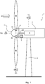
- FIG. 1 shows an embodiment of a wind turbine 1 according to the invention from a side view.
- the wind turbine 1 with pitch control comprises several components.
- a tower 2 which supports the other component of the wind turbine is fixed to the ground.
- the invention is not limited to on-shore installations but could also be used in connection with so-called off-shore installations where the tower is fixed to a structure in the sea.
- a nacelle 3 is rotatable mounted such that the nacelle 3 rotates around the axis TA of the tower 2.
- the nacelle 3 comprises a hub 4 and at least one rotor blade 6a which is rotatable fixed to the hub 4
- the wind turbine depicted in Figure 1 comprises three rotor blades 6a, 6b whereby only two rotor blades 6a, 6b are visible. The third rotor blade is not visible as it happens to be concealed by the hub. Hub 4 and rotor blades 6a, 6b, 6c are referred to also as the rotor of the wind turbine.
- Each rotor blade 6a, 6b is mounted to a pitch drive unit 9a, 9b.
- As the wind turbine 1 in this example has three rotor blades 6a, 6b, there are three pitch drive units 9a, 9b, 9c (not shown in Fig. 1 ), one for each rotor blade 6a, 6b.
- the three pitch drive units 9a, 9b, 9c are controlled by a pitch system controller 8.
- Each pitch drive unit 9a, 9b, 9c turns each rotor blade 6a, 6b around a rotor blade axis BA.
- the angle of attack of the rotor blades 6a, 6b to the wind W can be set to an angle between 0° and 90°, in some installations even negative angles or angles greater than 90° are known.
- the angle of attack may be chosen thus that the blades 6a, 6b produce no lift, produce maximum lift, or any desired lift in between these two extremes in response to a wind force W.
- the nacelle 3 is pivoted around its axis TA such that the rotor 4 is facing wind W.
- the rotor blades 6a, 6b are pitched such that the wind W generates lift on the rotor blades 6a, 6b, the lift will force the rotor 4 to spin around a rotor axis RA.
- An electric current generator 5 coupled by a generator shaft 50 to the rotor 4 produces electric energy which may be fed into an energy distributing net (not shown).
- the pitch angle of the rotor blades 6a, 6b eventually controls the rotation speed of the rotor 4 and thus also the amount of produced energy.
- the pitch system controller 8 and the three pitch drive units 9a, 9b, 9c constitute a pitch control sub system 8, 9a, 9b, 9c which controls the pitch angle of the rotor blades 6a, 6b independently from other sub systems of the wind turbine 1.
- a wind turbine may consist of several sub systems, for example another subsystem (not shown) for controlling the rotation of the nacelle 3 around the vertical axis TA and another subsystem comprising the current generator 5 for generating electric power.
- Each sub system may be supplied by a different manufacturer, respectively subcontractor and may be centrally controlled by the wind turbine control unit 7.
- FIG. 2 shows as a functional overview a pitch control system 8, 9a, 9b, 9c of a prior art wind turbine 1 interacting witch the wind turbine control unit 7.
- the pitch control system 8, 9a, 9b, 9c is powered by a power supply (not shown) which is connected to a power grid (not shown).
- a backup power supply (not shown) will supply, for a short time, the pitch control system 8, 9a, 9b, 9c with emergency power.
- one central backup power supply may be connected to the pitch control system 8, or individual backup power supplies may be assigned to each pitch drive 9a, 9b, 9c.
- Another design variation is to connect a backup power supply to the pitch control system 8 or the pitch drives 9a, 9b, 9c, respectively, only if a power failure occurs.
- the backup power supplies may be connected permanently to the pitch drives 9a. 9b, 9c.
- the backup power supply acts as a current buffer, In such an application the power supply needs to provide only the current for average power consumption of the pitch drives 9a, 9b, 9c.
- the permanently connected back up power supply enables the pitch drives 9a, 9b, 9c to consume more power in case the pitch drives 9a, 9b, 9c are commanded to run at maximum speed and/or maximum torque.
- the wind turbine control unit 7 controls via a data connection 7.01 a pitch system control module 8.
- This data connection 701 is for example a field bus.
- the pitch system control module 8 in turn controls via a data connection 801 three pitch drive control module 9.
- This data connection 801 is for example another field bus.
- the field buses may for example also be a single field bus that is used in common by all control equipment.
- Each pitch drive control module 9a, 9b, 9c eventually controls a motor 93a, 93b, 93c.
- Each motor is coupled, for example via gears 94a, 94b, 94c to the first, second, and third rotor blade 6a, 6b, 6c.
- the motors turn (pitch) the rotor blades to a specific angle, for example as commanded by the wind turbine controller 7.
- FIG. 3 shows illustrated as a block diagram an embodiment of a pitch system control module 8 and components it may comprise.
- the pitch system control module 8 may comprise one or more processors 811 and associated memory devices 812 configured to perform a variety of computer-implemented functions such as performing the method steps, calculations and the like and storing relevant data as disclosed herein.
- the pitch system control module 8 may be implemented as one or more printed card boards which are plugged into a pitch system controller card board carrier back plane (not shown).
- a sensor interface 813 permits signals transmitted from sensors 814 to be converted into signals that can be understood and processed by the processor 811.
- the sensors 814 may be coupled to the sensor interface 813 via a wired connection, which for example are electrically connected to the said pitch system controller card board carrier back plane. In other embodiments they may be coupled to the sensor interface via a wireless connection.
- the pitch system control module 8 also comprises a field bus interface 810 for communicating on the field bus 801 with the pitch drive control module 91. Via the field bus 801 further sensor data or other data from other parts of the wind turbine 1 can be received. Via this field bus 801, the pitch system control module 81 may be able to read the power that is generated by the electric generator in the nacelle 3. In this embodiment, the field bus 801 is also used to send and receive commands and data from three pitch drive control module 9 which individually control the pitch angle of each rotor blade 6a, 6b.
- FIG. 4 shows illustrated as a block diagram one embodiment of components that may be included within the pitch drive control module 9.
- the pitch drive control module 9 comprises one or more processors 911 and associated memory devices 912 configured to perform a variety of computer-implemented functions such as performing the method steps, calculations and the like and storing relevant data as disclosed herein.
- the pitch drive control module 9 may be implemented as one or more printed card boards which are plugged into a pitch drive unit card board carrier back plane (not shown).
- a sensor interface 913 permits signals transmitted from sensors 914 to be converted into signals that can be understood and processed by the processor 911.
- the sensors 914 may be coupled to the sensor interface 913 via a wired connection which for example are electrically connected to the said pitch drive unit card board carrier back plane. In other embodiments they may be coupled to the sensor interface via a wireless connection.
- the pitch drive control module 9 also comprises a field bus interface 910 for communicating on the field bus 801 with the pitch system control module 81. Via the field bus 801 further sensor data or other data from other parts of the wind turbine 1 can be received.
- the processor 911 of the pitch drive control module 9 is connected to a pulse width modulator circuit 915 to control the rotation of the electro mechanical motor 93 for rotating the rotor blades 6a, 6b around their axis BA.
- a safety control layer is implemented in each pitch drive 9 as a software module.
- the pitch system control module 8 and the three pitch drive control modules 9 are each running on processor systems developed according IEC 61508 and systematic capability greater safety integrity level SIL1. They are communicatively connected via the field bus 802 which also fulfils IEC 61508 and systematic capability greater safety integrity level SIL1.
- IEC 61508 is the international standard for electrical, electronic and programmable electronic safety related systems which sets out the requirements for ensuring that systems are designed, implemented, operated and maintained to provide a required safety integrity level (SIL).
- failures or errors may occur separately, or cumulative, for example a first error has occurred and while the first error is still present a second error, which is different to the first error occurs independently,
- a first error has occurred and while the first error is still present a second error, which is different to the first error occurs independently
- three basic errors that may occur in a pitch drive are described and three basic reactions to these errors are described.
- these errors are just examplatory and other errors may occur in addition or instead of the described errors.
- the pitch motors use a first angle sensor mounted close to an electric motor, for example on the motor shaft.
- This first angle sensor must be resistant to the heat the electric motor may produce when actuated.
- the type of angle sensor typically used for this purpose is called a resolver.
- the most common type of resolver is the brushless transmitter resolver with two two-phase windings, fixed at right angles to each other on a resolver stator, producing a sine and cosine feedback current. The relative magnitudes of the two-phase voltages are measured and used to determine the angle of a resolver rotor relative to the stator.
- the feedback signals repeat their waveforms upon one full revolution.
- Such resolvers typically have a resolution of about 0.1°.
- resolvers are available with self-diagnostics, so that in case the resolver becomes defective an error signal is generated.
- the unreliability of a resolver sensor signal may be also checked with a plausibility test.
- a first error of the pitch drive or if this is an isolated error, i.e. no other error is present, this is called a second error situation S2, as the error situation in which no error occurs is called the first error situation S1.
- the brushless DC motor is a synchronous electric motor with an electronically controlled commutation system.
- permanent magnets form the rotor.
- an electronic controller distributes the power stator windings such that a rotating magnet field is produced by the stator windings.
- the position of the rotor is known and by this the position of the permanent magnets. With this knowledge the motor controller can generate the rotating magnetic field so that the electric motor rotates exactly at the desired speed and torque. If provided with the respective control program a brushless DC motors can be operated without the information from a position sensor, i.e.
- Self-sensing mode could be based on the detection of the Back Electro Magnetic Force (BEMF) induced by the movement of a permanent magnet rotor in front of stator winding.
- BEMF Back Electro Magnetic Force
- the self-sensing mode analyzes for example zero crossing of BEMF in order to synchronize phase commutations. For lower speeds, where BEMF is small in amplitude the magnetic asymmetry of the motor may be used instead.
- a current sensor may be used to measure a so-called injection current signal. From the injection current signal for example a Kalman filter is used to estimate the position of the rotor.
- self-sensing modes are also available for brushed DC motors and synchronous AC motors.
- the pitch motors are operated with a resolver as a sensor for measuring the angle position of the motor shaft.
- the motor cannot be controlled accurately and in case of a blade encoder error the position of the rotor blade cannot be measured, risking that the pitch motor turns the rotor blade to the wrong position.
- the invention proposes in case a failure of the resolver is detected but no failure of the blade encoder is detected to switch the motor into self-sensing mode, which in the terminology of the claims is part of a first error procedure, or if it is the only reaction to the error, is the first error procedure.
- the maximum speed can be reduced, for example to half of the rotation speed in sensor mode, to account for the reduced torque in self-sensing mode.
- the rotation speed of the rotor blade may be limited at 6° per second in sensor mode and reduced to 3° per second in self-sensing mode.
- a gear box is provided between motor and the tooth ring on which the rotor blade is mounted.
- the gearbox and a toothed ring that is driven by the gearbox have a transmission ratio of 1:1000 to 1: 2000.
- the position of the rotor blade may be calculated from the resolver data.
- a second angle decoder is provided at the vicinity of the rotor blade to measure the angle position of the rotor blade. For example in the feathering position the angle of the rotor blades are 90°. For a full angle of attack to the wind they are turned substantially into a 0° position.
- Common angle encoders used for this location have for example a resolution of sixteen bit for a full 360° turn, which results in a resolution of approximately 0.005°.
- twelve or thirteen bit multi-turn encoders may be attached to an output of a gear, i.e. at the side of the gear where the rotor blades are attached to.
- a gear box with a ratio of 1:100 to 1: 200 increases the resolution of the angle measured at the input of the gear, i.e. the side of the gear where the motor is attached to, effectively up to 0.0002°. Due to their relatively low temperature range such high precision angle decoders cannot be used close to the electrical motor.
- a blade encoder error is detected this is termed in this application a second error situation, if the blade encoder error occurs in isolated form, i.e. no other error is present.
- the invention proposes as a second error procedure to mitigate this second error situation to use the resolver information of the pitch motor to calculate the position of the rotor blade. Due to backslash of the gearbox etc. this may not be as accurate as the information from the blade encoder, but it is sufficient to stop the rotor blade at approximately 90°, still avoiding that sufficient lift is produced by the blade to restart propelling the rotor of the wind turbine.
- the resolver in contrast hereto usually produces relative values
- the pitch drive controller at start-up uses the absolute position provided by the blade encoder to reference the resolver encoder and continuously calculates and compares the resolver position with the blade encoder position.
- the device controller can use the continuously calculated position to switch seamlessly from resolver mode into self-sensing mode.
- a voltage sensor in this embodiment is used as, for example, to measure the capacity of a back-up power supply.
- the backup power supply should power the pitch drive motors at least as long as they need to turn the rotor blades into the feathering position.
- the analysis of the resolver, the blade encoder, and the backup power supply are reduced to a simple binary decision "failure" or "no failure" of each analysed device.
- a failure of the backup power supply is detected, this is termed in this application a third error.
- the third error occurs isolated, i.e. with no other error present this is termed a third error situation S4.
- the invention proposes in a third error procedure to turn the other pitch drivers in the feathering position, which eventually will stop the rotor, even if one of the rotor blades is not able to turn to the feathering position.
- the third error procedure may also limit the speed of the pitch motor to a second limited speed. This second speed limit takes into account that the backup power supply in this special embodiment is permanently connected to the power supply to support a high current that is required by the pitch motor when turning at high speed and/or high torque.
- this additional power is no longer commanding the pitch motor to turn at high speed and/or at a high torque may cause a breakdown of the power supply.
- this second limited speed may be even lower than for self-sensing mode, for example 2° per second.
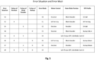
- Figure 5 shows in a table in a first column eight different error scenarios, or eight different error situations.
- This first column is labelled "Error situation”
- a second column is labeled "Failure of Resolver” and shows for each error situation the error status of the resolver, whereby a failure of the resolver is indicated by an "X” and a failure free functioning resolver is indicated by a blank cell.
- a third column labelled “Failure of Blade Encoder” shows a failure of the blade encoder indicated also by an "X” and a failure free functioning of the blade encoder as a blank cell.
- a fourth column labelled “Failure backup” shows a failure of the backup system indicated by an "X” and a failure free functioning backup indicated by a blank cell.
- the eight error situations S1, S2, S3, S4, S5, S6, S7, S8 are mapped to seven error modes, an error free mode E0, a first error mode E1, a second error mode E2, a third error mode E3, a fourth error mode E4, a fifth error mode E5, and a sixth error mode E6.
- the pitch drive uses a different failure mitigation strategy, e.g. a different error procedure, which is described in the sixth column labelled "Motor Control", the seventh column labelled "Rotor Blade Position" and the eight column labelled "SFR Profile".
- the fifth error situation S5 and the eight error situation S8 differ in the failure status of the backup, they share the same error mode E4.
- the first line after the column headings of the table of Figure 5 shows the first error situation S1 in which, as described above, the resolver, the blade encoder and the backup have been analysed to work properly, i.e. without any indication of a failure. Consequently, the error mode that is assigned to this modus is called "error free" mode E0.
- the error free mode E0 is assigned to the first error situation S1.
- the output value of the blade encoder is used by the controller to measure at any time the position of the rotor blade. Once the blade encoder transmits an angle of 90° to the controller, the controller can rely on this input value and will stop rotating the rotor blade when it has reached the final position for the feathering position.
- the controller controls the motor by using the high resolution data of the resolver. Also, as the back-up power supply does not indicate an error, the commands from the wind turbine controller are transparently forwarded from the controller to the controller. This is indicated in the table in the column SFR Profile (SFR stands for Safe Feathering Run) by the word " default " which means that the controller does not apply any modifications to the speed of the motors.
- SFR Profile SFR stands for Safe Feathering Run
- the second error situation S2 is entered in case a failure of the resolver is detected, but no failure of the blade encoder and no failure of the backup have been detected.
- the first error mode E1 is assigned to this second error situation. This error mode has been discussed earlier above.
- the pitch motor is switched from sensor mode, i.e. controlled by the resolver, into self-sensing mode. As explained above, the pitch motor speed in the self-sensing mode is limited to a first speed limit.
- the controller in this case, uses an SFR profile which is called " self-sensing ".
- the controller When the " self-sensing " profile is applied the controller will modify the received commands so that when they are forwarded to the controller, the speed of the pitch motor is limited to the first speed limit.
- the limiting of the rotation speed of the pitch motor is just one example. In an SFR profile, other limitations may be applied to the controller, such as maximum current respectively torque limits.
- the rotor blade position is determined by using the resolver of the pitch motor. As the resolver is not affected, the motor can operate in the usual sensor mode and the SFR profile can remain as the default profile. However, due to the less accurate determined rotor blade position, a profile especially designed for that purpose may be used.
- the controller detects a failure of the power backup but resolver and blade encoder are indicating to work without errors this situation is classified as the fourth error situation to which the third error mode E4 is assigned to.
- the third error mode E4 a special " backup failure " profile is applied.
- the speed of the pitch drive is reduced to a second speed limit.
- other alternative or additional measures may be applied by the controller.
- the invention proposes to prevent any movement by the pitch motor, to engage the mechanical brake and to request the other pitch drives to turn their rotor blades into the feathering position.
- the preventing of any movement can be achieved by resetting any commands received by the controller to a command that sets the speed to zero, respectively a command that stops the motor.
- the controller may use additional circuitry to block the controls of the pitch motor, for example by interrupting by means of switches the power supply to the a power inverter.
- all control inputs of the drive circuitry for example the input lead of an H-bridge can be connected with zero voltage, so that independent whatever control signals are produced in the pitch drive, these control signals are short-circuited to a ground voltage and thus effectively overwritten.
- additional circuitry that is controlled for example by control signals 919 of the controller 91.
- the controller detects the failure of the resolver and a failure of the backup power supply but no failure of the late encoder this situation is classified as the sixth error situation to which the fifth error mode E5 is assigned to.
- the fifth error mode E5 the rotor blade position is directly derived from the blade encoder as the blade encoder works without error. Due to the failure of the resolver, the motor control is set into self-sensing mode. Due to the failure of the backup power supply the SFR profile chosen by the controller is the " backup-failure " profile.
- the controller detects the failure of the blade encoder and at the same time the failure of the backup, but the resolver is reported to work without failure, this situation is classified as the sixth error situation S7, to which the sixth error mode is assigned to.
- the sixth error mode E6 the motor control continues in resolver mode, whereas the rotor blade position is measured by the resolver. Due to the backup failure, the chosen SFR profile is the " backup-failure " profile.
- the controller classifies this as the eight error situation, to which the fourth error mode E4, is assigned to., As pointed out above the fifth error situation S5 and the eighth error situation S8 share the same error mode E4.
- the measures taken in this case are safe torque off and safe break control.
- the pitch motor is stopped at once, the SFR profile applied does not matter. Important is only that the controller is reporting the fourth mode error E4 to the other pitch drives so that the other pitch drives are commanded into a feathering run. Theoretically, however, the action " Safe Torque Off " may also be seen as a special SFR profile.
- some error modes are not only a pure combination of the measures in case a single failure has occurred.
- the reaction to a combination of a resolver failure and a blade encoder failure, which is safe torque off is not equivalent to a combination of the first error mode E1 and the second error mode E2. Therefore, the three different types of errors of this embodiment are dealt with in different ways when a combination of errors occurs.
- Figure 6 shows the transitions between the error free mode E0 and the first error mode E1, the second error mode E2, the third error mode E3, the fourth error mode E4, the fifth error mode E5, and the sixth error mode E6.
- An autonomous movement of the rotor blades into the feathering position does not necessarily mean that it was caused by an error.
- the autonomous movement can also be started intentionally by the user when he wants, for example, to stop the wind turbine for maintenance purposes. In this case, the wind turbine would be in the error free mode E0.
- a command " Normal Stop " would be used which allows a kind of soft slowing down of the rotor of the wind turbine.
- the pitch drive stays in error-free mode E0 until it has reached the feathering position as planned.
- error-free mode E0 as shown in Figure 6 , three error conditions may arise.
- the pitch drive is adapted to transit to error mode E1; in case of a blade encoder failure it will transit to error mode E2; and in case of a back-up failure it will transit to error mode E3.
- the deterministic system will process one of the two or more errors one after the other. In the first error mode E1, only two more errors will be evaluated.
- a blade encoder error will transit the first error mode E1 into fourth error mode E4 and a backup failure will transit the first error mode E1 into the fifth error mode E5.
- a resolver error will transit the pitch drive into the fourth error mode E4 and a blade encoder error will transit the second error mode E2 into the sixth error mode E6.
- a resolver error will transit the third error mode E3 into the fourth error mode E4 and in case of a backup failure, the pitch drive is transited to sixth error mode E6.
- the fifth error mode E5 is transited into the fourth error mode E4 and in case of a resolver error, the sixth error mode E6 is transited into the fourth error mode E4.
- E4 is the ultimate error mode as it is only applicable when all three evaluated error conditions have occurred.
Landscapes
- Engineering & Computer Science (AREA)
- Life Sciences & Earth Sciences (AREA)
- Sustainable Development (AREA)
- Sustainable Energy (AREA)
- Chemical & Material Sciences (AREA)
- Combustion & Propulsion (AREA)
- Mechanical Engineering (AREA)
- General Engineering & Computer Science (AREA)
- Physics & Mathematics (AREA)
- Fluid Mechanics (AREA)
- Wind Motors (AREA)
Applications Claiming Priority (1)
| Application Number | Priority Date | Filing Date | Title |
|---|---|---|---|
| GBGB1622211.9A GB201622211D0 (en) | 2016-12-23 | 2016-12-23 | Method for controlling a wind turbine with increased safety |
Publications (2)
| Publication Number | Publication Date |
|---|---|
| EP3343029A1 true EP3343029A1 (fr) | 2018-07-04 |
| EP3343029B1 EP3343029B1 (fr) | 2021-12-01 |
Family
ID=58360667
Family Applications (1)
| Application Number | Title | Priority Date | Filing Date |
|---|---|---|---|
| EP17210754.2A Active EP3343029B1 (fr) | 2016-12-23 | 2017-12-27 | Gestion de mode d'erreur de moteurs à pas variable d'une éolienne |
Country Status (6)
| Country | Link |
|---|---|
| US (1) | US11156205B2 (fr) |
| EP (1) | EP3343029B1 (fr) |
| CN (1) | CN108240285B (fr) |
| DK (1) | DK3343029T3 (fr) |
| ES (1) | ES2907578T3 (fr) |
| GB (1) | GB201622211D0 (fr) |
Cited By (1)
| Publication number | Priority date | Publication date | Assignee | Title |
|---|---|---|---|---|
| EP4134543A1 (fr) * | 2021-08-09 | 2023-02-15 | Siemens Gamesa Renewable Energy A/S | Procédé d'arrêt d'une opération d'une turbine éolienne flottante |
Families Citing this family (4)
| Publication number | Priority date | Publication date | Assignee | Title |
|---|---|---|---|---|
| EP3667070A1 (fr) * | 2018-12-13 | 2020-06-17 | Siemens Gamesa Renewable Energy A/S | État sécurisé d'une pale de turbine éolienne adaptable |
| CN112523946B (zh) * | 2019-09-17 | 2022-10-18 | 北京金风科创风电设备有限公司 | 风力发电机组的变桨控制方法、装置及介质 |
| DE102019125789A1 (de) * | 2019-09-25 | 2021-03-25 | Keba Industrial Automation Germany Gmbh | Pitch-Antriebsregler einer Windkraftanlage, Pitch-Antriebssteuergerät und Verfahren zum Steuern eines Pitch-Antriebsreglers |
| CN110608133B (zh) * | 2019-10-28 | 2020-10-02 | 国网山东省电力公司电力科学研究院 | 一种海上风力发电控制系统及方法 |
Citations (3)
| Publication number | Priority date | Publication date | Assignee | Title |
|---|---|---|---|---|
| US20110148112A1 (en) * | 2008-03-07 | 2011-06-23 | Vestas Wind Systems A/S | Control System and a Method for Controlling a Wind Turbine |
| US20120219421A1 (en) * | 2009-08-24 | 2012-08-30 | Mikael Bjork | Control system for a wind turbine |
| US20140028025A1 (en) * | 2011-04-14 | 2014-01-30 | Suzlon Energy Gmbh | Device and method for determining a blade position and for ending a safety run |
Family Cites Families (2)
| Publication number | Priority date | Publication date | Assignee | Title |
|---|---|---|---|---|
| CN102758726A (zh) | 2011-04-25 | 2012-10-31 | 华锐风电科技(集团)股份有限公司 | 变桨控制系统、变桨控制方法和风力发电机组 |
| CN104832371B (zh) | 2015-05-28 | 2017-10-24 | 大唐山东烟台电力开发有限公司 | 一种风力发电机组控制方法和系统 |
-
2016
- 2016-12-23 GB GBGB1622211.9A patent/GB201622211D0/en not_active Ceased
-
2017
- 2017-12-20 US US15/848,128 patent/US11156205B2/en active Active
- 2017-12-22 CN CN201711403547.6A patent/CN108240285B/zh active Active
- 2017-12-27 EP EP17210754.2A patent/EP3343029B1/fr active Active
- 2017-12-27 ES ES17210754T patent/ES2907578T3/es active Active
- 2017-12-27 DK DK17210754.2T patent/DK3343029T3/da active
Patent Citations (3)
| Publication number | Priority date | Publication date | Assignee | Title |
|---|---|---|---|---|
| US20110148112A1 (en) * | 2008-03-07 | 2011-06-23 | Vestas Wind Systems A/S | Control System and a Method for Controlling a Wind Turbine |
| US20120219421A1 (en) * | 2009-08-24 | 2012-08-30 | Mikael Bjork | Control system for a wind turbine |
| US20140028025A1 (en) * | 2011-04-14 | 2014-01-30 | Suzlon Energy Gmbh | Device and method for determining a blade position and for ending a safety run |
Non-Patent Citations (1)
| Title |
|---|
| TOBIAS ROSMANN ET AL: "Analysis of instability of direct powered DC-compound machines in pitch systems of large wind turbines", INDUSTRIAL TECHNOLOGY (ICIT), 2010 IEEE INTERNATIONAL CONFERENCE ON, IEEE, PISCATAWAY, NJ, USA, 14 March 2010 (2010-03-14), pages 323 - 329, XP031681147, ISBN: 978-1-4244-5695-6 * |
Cited By (2)
| Publication number | Priority date | Publication date | Assignee | Title |
|---|---|---|---|---|
| EP4134543A1 (fr) * | 2021-08-09 | 2023-02-15 | Siemens Gamesa Renewable Energy A/S | Procédé d'arrêt d'une opération d'une turbine éolienne flottante |
| WO2023016911A1 (fr) * | 2021-08-09 | 2023-02-16 | Siemens Gamesa Renewable Energy A/S | Procédé d'arrêt du fonctionnement d'une éolienne flottante |
Also Published As
| Publication number | Publication date |
|---|---|
| ES2907578T3 (es) | 2022-04-25 |
| GB201622211D0 (en) | 2017-02-08 |
| CN108240285A (zh) | 2018-07-03 |
| US20180180023A1 (en) | 2018-06-28 |
| US11156205B2 (en) | 2021-10-26 |
| DK3343029T3 (da) | 2022-03-07 |
| EP3343029B1 (fr) | 2021-12-01 |
| CN108240285B (zh) | 2021-10-01 |
Similar Documents
| Publication | Publication Date | Title |
|---|---|---|
| EP3343029B1 (fr) | Gestion de mode d'erreur de moteurs à pas variable d'une éolienne | |
| US20190010924A1 (en) | Method for controlling a machine or process with increased safety | |
| KR101991051B1 (ko) | 전기기계식 구동 시스템 | |
| JP6247957B2 (ja) | 風力発電装置のヨー制御システム及びヨー制御方法 | |
| JP5367623B2 (ja) | サーボシステム、サーボモータ駆動装置、セーフティユニットおよびサーボシステムの制御方法 | |
| CN102594235B (zh) | 步进马达的驱动电路以及驱动方法 | |
| JP2008022590A (ja) | サーボモータ監視装置 | |
| EP4116582B1 (fr) | Capteurs d'azimut dans des éoliennes | |
| JP3200510B2 (ja) | モータ制御装置 | |
| CN110061673A (zh) | 基于霍尔传感器的电机控制方法及系统 | |
| CA2884649C (fr) | Systeme et methode de controle d'un composant electronique d'une eolienne a l'aide de communications d'eventualite | |
| JP4210098B2 (ja) | モータ駆動装置 | |
| JP5904038B2 (ja) | 角度情報伝送方法および角度情報伝送システム | |
| CN207454186U (zh) | 一种风机偏航及扭缆检测装置 | |
| US11293403B2 (en) | System and method for preventing catastrophic damage in drivetrain of a wind turbine | |
| JP2008289361A (ja) | モータ駆動装置 | |
| US20230042139A1 (en) | System and Method for Monitoring a Failsafe Function of Sensors in a Motor | |
| JP5095277B2 (ja) | 同期電動機の駆動装置 | |
| US12113463B2 (en) | Motor control device | |
| EP4542031A1 (fr) | Procédé de fonctionnement d'une éolienne et éolienne | |
| EP4484745A1 (fr) | Procédé de fonctionnement d'une éolienne et éolienne | |
| JP7326822B2 (ja) | モータ制御装置 | |
| RU2809179C2 (ru) | Способ выполнения переключения переключателя ступеней нагрузки посредством приводной системы и приводная система для переключателя ступеней нагрузки | |
| JP2025143090A (ja) | アクチュエータシステム | |
| CN119712423A (zh) | 风力发电机组盘车控制方法、装置及系统 |
Legal Events
| Date | Code | Title | Description |
|---|---|---|---|
| PUAI | Public reference made under article 153(3) epc to a published international application that has entered the european phase |
Free format text: ORIGINAL CODE: 0009012 |
|
| STAA | Information on the status of an ep patent application or granted ep patent |
Free format text: STATUS: THE APPLICATION HAS BEEN PUBLISHED |
|
| AK | Designated contracting states |
Kind code of ref document: A1 Designated state(s): AL AT BE BG CH CY CZ DE DK EE ES FI FR GB GR HR HU IE IS IT LI LT LU LV MC MK MT NL NO PL PT RO RS SE SI SK SM TR |
|
| AX | Request for extension of the european patent |
Extension state: BA ME |
|
| STAA | Information on the status of an ep patent application or granted ep patent |
Free format text: STATUS: REQUEST FOR EXAMINATION WAS MADE |
|
| 17P | Request for examination filed |
Effective date: 20190104 |
|
| RBV | Designated contracting states (corrected) |
Designated state(s): AL AT BE BG CH CY CZ DE DK EE ES FI FR GB GR HR HU IE IS IT LI LT LU LV MC MK MT NL NO PL PT RO RS SE SI SK SM TR |
|
| RAP1 | Party data changed (applicant data changed or rights of an application transferred) |
Owner name: LTI MOTION GMBH |
|
| RAP1 | Party data changed (applicant data changed or rights of an application transferred) |
Owner name: KEBA INDUSTRIAL AUTOMATION GERMANY GMBH |
|
| STAA | Information on the status of an ep patent application or granted ep patent |
Free format text: STATUS: EXAMINATION IS IN PROGRESS |
|
| 17Q | First examination report despatched |
Effective date: 20200810 |
|
| GRAP | Despatch of communication of intention to grant a patent |
Free format text: ORIGINAL CODE: EPIDOSNIGR1 |
|
| STAA | Information on the status of an ep patent application or granted ep patent |
Free format text: STATUS: GRANT OF PATENT IS INTENDED |
|
| INTG | Intention to grant announced |
Effective date: 20210721 |
|
| GRAS | Grant fee paid |
Free format text: ORIGINAL CODE: EPIDOSNIGR3 |
|
| GRAA | (expected) grant |
Free format text: ORIGINAL CODE: 0009210 |
|
| STAA | Information on the status of an ep patent application or granted ep patent |
Free format text: STATUS: THE PATENT HAS BEEN GRANTED |
|
| AK | Designated contracting states |
Kind code of ref document: B1 Designated state(s): AL AT BE BG CH CY CZ DE DK EE ES FI FR GB GR HR HU IE IS IT LI LT LU LV MC MK MT NL NO PL PT RO RS SE SI SK SM TR |
|
| REG | Reference to a national code |
Ref country code: GB Ref legal event code: FG4D |
|
| REG | Reference to a national code |
Ref country code: AT Ref legal event code: REF Ref document number: 1451997 Country of ref document: AT Kind code of ref document: T Effective date: 20211215 Ref country code: CH Ref legal event code: EP |
|
| REG | Reference to a national code |
Ref country code: IE Ref legal event code: FG4D |
|
| REG | Reference to a national code |
Ref country code: DE Ref legal event code: R096 Ref document number: 602017050116 Country of ref document: DE |
|
| REG | Reference to a national code |
Ref country code: DK Ref legal event code: T3 Effective date: 20220302 |
|
| REG | Reference to a national code |
Ref country code: SE Ref legal event code: TRGR |
|
| REG | Reference to a national code |
Ref country code: LT Ref legal event code: MG9D |
|
| REG | Reference to a national code |
Ref country code: NL Ref legal event code: MP Effective date: 20211201 |
|
| REG | Reference to a national code |
Ref country code: AT Ref legal event code: MK05 Ref document number: 1451997 Country of ref document: AT Kind code of ref document: T Effective date: 20211201 |
|
| REG | Reference to a national code |
Ref country code: ES Ref legal event code: FG2A Ref document number: 2907578 Country of ref document: ES Kind code of ref document: T3 Effective date: 20220425 |
|
| PG25 | Lapsed in a contracting state [announced via postgrant information from national office to epo] |
Ref country code: RS Free format text: LAPSE BECAUSE OF FAILURE TO SUBMIT A TRANSLATION OF THE DESCRIPTION OR TO PAY THE FEE WITHIN THE PRESCRIBED TIME-LIMIT Effective date: 20211201 Ref country code: LT Free format text: LAPSE BECAUSE OF FAILURE TO SUBMIT A TRANSLATION OF THE DESCRIPTION OR TO PAY THE FEE WITHIN THE PRESCRIBED TIME-LIMIT Effective date: 20211201 Ref country code: FI Free format text: LAPSE BECAUSE OF FAILURE TO SUBMIT A TRANSLATION OF THE DESCRIPTION OR TO PAY THE FEE WITHIN THE PRESCRIBED TIME-LIMIT Effective date: 20211201 Ref country code: BG Free format text: LAPSE BECAUSE OF FAILURE TO SUBMIT A TRANSLATION OF THE DESCRIPTION OR TO PAY THE FEE WITHIN THE PRESCRIBED TIME-LIMIT Effective date: 20220301 Ref country code: AT Free format text: LAPSE BECAUSE OF FAILURE TO SUBMIT A TRANSLATION OF THE DESCRIPTION OR TO PAY THE FEE WITHIN THE PRESCRIBED TIME-LIMIT Effective date: 20211201 |
|
| PG25 | Lapsed in a contracting state [announced via postgrant information from national office to epo] |
Ref country code: PL Free format text: LAPSE BECAUSE OF FAILURE TO SUBMIT A TRANSLATION OF THE DESCRIPTION OR TO PAY THE FEE WITHIN THE PRESCRIBED TIME-LIMIT Effective date: 20211201 Ref country code: NO Free format text: LAPSE BECAUSE OF FAILURE TO SUBMIT A TRANSLATION OF THE DESCRIPTION OR TO PAY THE FEE WITHIN THE PRESCRIBED TIME-LIMIT Effective date: 20220301 Ref country code: LV Free format text: LAPSE BECAUSE OF FAILURE TO SUBMIT A TRANSLATION OF THE DESCRIPTION OR TO PAY THE FEE WITHIN THE PRESCRIBED TIME-LIMIT Effective date: 20211201 Ref country code: HR Free format text: LAPSE BECAUSE OF FAILURE TO SUBMIT A TRANSLATION OF THE DESCRIPTION OR TO PAY THE FEE WITHIN THE PRESCRIBED TIME-LIMIT Effective date: 20211201 Ref country code: GR Free format text: LAPSE BECAUSE OF FAILURE TO SUBMIT A TRANSLATION OF THE DESCRIPTION OR TO PAY THE FEE WITHIN THE PRESCRIBED TIME-LIMIT Effective date: 20220302 |
|
| PG25 | Lapsed in a contracting state [announced via postgrant information from national office to epo] |
Ref country code: NL Free format text: LAPSE BECAUSE OF FAILURE TO SUBMIT A TRANSLATION OF THE DESCRIPTION OR TO PAY THE FEE WITHIN THE PRESCRIBED TIME-LIMIT Effective date: 20211201 |
|
| PG25 | Lapsed in a contracting state [announced via postgrant information from national office to epo] |
Ref country code: SM Free format text: LAPSE BECAUSE OF FAILURE TO SUBMIT A TRANSLATION OF THE DESCRIPTION OR TO PAY THE FEE WITHIN THE PRESCRIBED TIME-LIMIT Effective date: 20211201 Ref country code: SK Free format text: LAPSE BECAUSE OF FAILURE TO SUBMIT A TRANSLATION OF THE DESCRIPTION OR TO PAY THE FEE WITHIN THE PRESCRIBED TIME-LIMIT Effective date: 20211201 Ref country code: RO Free format text: LAPSE BECAUSE OF FAILURE TO SUBMIT A TRANSLATION OF THE DESCRIPTION OR TO PAY THE FEE WITHIN THE PRESCRIBED TIME-LIMIT Effective date: 20211201 Ref country code: PT Free format text: LAPSE BECAUSE OF FAILURE TO SUBMIT A TRANSLATION OF THE DESCRIPTION OR TO PAY THE FEE WITHIN THE PRESCRIBED TIME-LIMIT Effective date: 20220401 Ref country code: EE Free format text: LAPSE BECAUSE OF FAILURE TO SUBMIT A TRANSLATION OF THE DESCRIPTION OR TO PAY THE FEE WITHIN THE PRESCRIBED TIME-LIMIT Effective date: 20211201 Ref country code: CZ Free format text: LAPSE BECAUSE OF FAILURE TO SUBMIT A TRANSLATION OF THE DESCRIPTION OR TO PAY THE FEE WITHIN THE PRESCRIBED TIME-LIMIT Effective date: 20211201 |
|
| REG | Reference to a national code |
Ref country code: CH Ref legal event code: PL |
|
| PG25 | Lapsed in a contracting state [announced via postgrant information from national office to epo] |
Ref country code: MC Free format text: LAPSE BECAUSE OF FAILURE TO SUBMIT A TRANSLATION OF THE DESCRIPTION OR TO PAY THE FEE WITHIN THE PRESCRIBED TIME-LIMIT Effective date: 20211201 |
|
| REG | Reference to a national code |
Ref country code: DE Ref legal event code: R097 Ref document number: 602017050116 Country of ref document: DE |
|
| REG | Reference to a national code |
Ref country code: BE Ref legal event code: MM Effective date: 20211231 |
|
| PG25 | Lapsed in a contracting state [announced via postgrant information from national office to epo] |
Ref country code: IS Free format text: LAPSE BECAUSE OF FAILURE TO SUBMIT A TRANSLATION OF THE DESCRIPTION OR TO PAY THE FEE WITHIN THE PRESCRIBED TIME-LIMIT Effective date: 20220401 |
|
| PLBE | No opposition filed within time limit |
Free format text: ORIGINAL CODE: 0009261 |
|
| STAA | Information on the status of an ep patent application or granted ep patent |
Free format text: STATUS: NO OPPOSITION FILED WITHIN TIME LIMIT |
|
| PG25 | Lapsed in a contracting state [announced via postgrant information from national office to epo] |
Ref country code: LU Free format text: LAPSE BECAUSE OF NON-PAYMENT OF DUE FEES Effective date: 20211227 Ref country code: IE Free format text: LAPSE BECAUSE OF NON-PAYMENT OF DUE FEES Effective date: 20211227 Ref country code: AL Free format text: LAPSE BECAUSE OF FAILURE TO SUBMIT A TRANSLATION OF THE DESCRIPTION OR TO PAY THE FEE WITHIN THE PRESCRIBED TIME-LIMIT Effective date: 20211201 |
|
| 26N | No opposition filed |
Effective date: 20220902 |
|
| PG25 | Lapsed in a contracting state [announced via postgrant information from national office to epo] |
Ref country code: SI Free format text: LAPSE BECAUSE OF FAILURE TO SUBMIT A TRANSLATION OF THE DESCRIPTION OR TO PAY THE FEE WITHIN THE PRESCRIBED TIME-LIMIT Effective date: 20211201 Ref country code: BE Free format text: LAPSE BECAUSE OF NON-PAYMENT OF DUE FEES Effective date: 20211231 |
|
| PG25 | Lapsed in a contracting state [announced via postgrant information from national office to epo] |
Ref country code: LI Free format text: LAPSE BECAUSE OF NON-PAYMENT OF DUE FEES Effective date: 20211231 Ref country code: CH Free format text: LAPSE BECAUSE OF NON-PAYMENT OF DUE FEES Effective date: 20211231 |
|
| PG25 | Lapsed in a contracting state [announced via postgrant information from national office to epo] |
Ref country code: IT Free format text: LAPSE BECAUSE OF FAILURE TO SUBMIT A TRANSLATION OF THE DESCRIPTION OR TO PAY THE FEE WITHIN THE PRESCRIBED TIME-LIMIT Effective date: 20211201 Ref country code: HU Free format text: LAPSE BECAUSE OF FAILURE TO SUBMIT A TRANSLATION OF THE DESCRIPTION OR TO PAY THE FEE WITHIN THE PRESCRIBED TIME-LIMIT; INVALID AB INITIO Effective date: 20171227 |
|
| PG25 | Lapsed in a contracting state [announced via postgrant information from national office to epo] |
Ref country code: CY Free format text: LAPSE BECAUSE OF FAILURE TO SUBMIT A TRANSLATION OF THE DESCRIPTION OR TO PAY THE FEE WITHIN THE PRESCRIBED TIME-LIMIT Effective date: 20211201 |
|
| PG25 | Lapsed in a contracting state [announced via postgrant information from national office to epo] |
Ref country code: MK Free format text: LAPSE BECAUSE OF FAILURE TO SUBMIT A TRANSLATION OF THE DESCRIPTION OR TO PAY THE FEE WITHIN THE PRESCRIBED TIME-LIMIT Effective date: 20211201 |
|
| PG25 | Lapsed in a contracting state [announced via postgrant information from national office to epo] |
Ref country code: TR Free format text: LAPSE BECAUSE OF FAILURE TO SUBMIT A TRANSLATION OF THE DESCRIPTION OR TO PAY THE FEE WITHIN THE PRESCRIBED TIME-LIMIT Effective date: 20211201 |
|
| PG25 | Lapsed in a contracting state [announced via postgrant information from national office to epo] |
Ref country code: MT Free format text: LAPSE BECAUSE OF FAILURE TO SUBMIT A TRANSLATION OF THE DESCRIPTION OR TO PAY THE FEE WITHIN THE PRESCRIBED TIME-LIMIT Effective date: 20211201 |
|
| PGFP | Annual fee paid to national office [announced via postgrant information from national office to epo] |
Ref country code: GB Payment date: 20251218 Year of fee payment: 9 |
|
| PGFP | Annual fee paid to national office [announced via postgrant information from national office to epo] |
Ref country code: DK Payment date: 20251217 Year of fee payment: 9 |
|
| PGFP | Annual fee paid to national office [announced via postgrant information from national office to epo] |
Ref country code: FR Payment date: 20251217 Year of fee payment: 9 |
|
| PGFP | Annual fee paid to national office [announced via postgrant information from national office to epo] |
Ref country code: SE Payment date: 20251217 Year of fee payment: 9 |
|
| PGFP | Annual fee paid to national office [announced via postgrant information from national office to epo] |
Ref country code: ES Payment date: 20260119 Year of fee payment: 9 |
|
| PGFP | Annual fee paid to national office [announced via postgrant information from national office to epo] |
Ref country code: DE Payment date: 20251218 Year of fee payment: 9 |