EP3343032A1 - Antriebsvorrichtung für eine fluidpumpe - Google Patents
Antriebsvorrichtung für eine fluidpumpe Download PDFInfo
- Publication number
- EP3343032A1 EP3343032A1 EP17210615.5A EP17210615A EP3343032A1 EP 3343032 A1 EP3343032 A1 EP 3343032A1 EP 17210615 A EP17210615 A EP 17210615A EP 3343032 A1 EP3343032 A1 EP 3343032A1
- Authority
- EP
- European Patent Office
- Prior art keywords
- speed
- fluid pump
- drive device
- drive
- frequency converter
- Prior art date
- Legal status (The legal status is an assumption and is not a legal conclusion. Google has not performed a legal analysis and makes no representation as to the accuracy of the status listed.)
- Granted
Links
Images

Classifications
-
- F—MECHANICAL ENGINEERING; LIGHTING; HEATING; WEAPONS; BLASTING
- F04—POSITIVE - DISPLACEMENT MACHINES FOR LIQUIDS; PUMPS FOR LIQUIDS OR ELASTIC FLUIDS
- F04B—POSITIVE-DISPLACEMENT MACHINES FOR LIQUIDS; PUMPS
- F04B17/00—Pumps characterised by combination with, or adaptation to, specific driving engines or motors
- F04B17/03—Pumps characterised by combination with, or adaptation to, specific driving engines or motors driven by electric motors
-
- F—MECHANICAL ENGINEERING; LIGHTING; HEATING; WEAPONS; BLASTING
- F04—POSITIVE - DISPLACEMENT MACHINES FOR LIQUIDS; PUMPS FOR LIQUIDS OR ELASTIC FLUIDS
- F04B—POSITIVE-DISPLACEMENT MACHINES FOR LIQUIDS; PUMPS
- F04B49/00—Control, e.g. of pump delivery, or pump pressure of, or safety measures for, machines, pumps, or pumping installations, not otherwise provided for, or of interest apart from, groups F04B1/00 - F04B47/00
- F04B49/06—Control using electricity
-
- F—MECHANICAL ENGINEERING; LIGHTING; HEATING; WEAPONS; BLASTING
- F04—POSITIVE - DISPLACEMENT MACHINES FOR LIQUIDS; PUMPS FOR LIQUIDS OR ELASTIC FLUIDS
- F04B—POSITIVE-DISPLACEMENT MACHINES FOR LIQUIDS; PUMPS
- F04B49/00—Control, e.g. of pump delivery, or pump pressure of, or safety measures for, machines, pumps, or pumping installations, not otherwise provided for, or of interest apart from, groups F04B1/00 - F04B47/00
- F04B49/06—Control using electricity
- F04B49/065—Control using electricity and making use of computers
-
- F—MECHANICAL ENGINEERING; LIGHTING; HEATING; WEAPONS; BLASTING
- F04—POSITIVE - DISPLACEMENT MACHINES FOR LIQUIDS; PUMPS FOR LIQUIDS OR ELASTIC FLUIDS
- F04B—POSITIVE-DISPLACEMENT MACHINES FOR LIQUIDS; PUMPS
- F04B49/00—Control, e.g. of pump delivery, or pump pressure of, or safety measures for, machines, pumps, or pumping installations, not otherwise provided for, or of interest apart from, groups F04B1/00 - F04B47/00
- F04B49/20—Control, e.g. of pump delivery, or pump pressure of, or safety measures for, machines, pumps, or pumping installations, not otherwise provided for, or of interest apart from, groups F04B1/00 - F04B47/00 by changing the driving speed
Definitions
- the invention relates to a drive device for a fluid pump with a conveyor, which is designed to promote a delivery volume in each revolution, and a method for operating a fluid pump.
- the drive device comprises a drive motor for driving the conveyor at a speed.
- variable speed pumps Methods are known in which the energy efficiency of variable speed pumps is improved.
- the speed of the drive can be specified as a manipulated variable.
- the control is done on the pump itself.
- external sensors e.g. for determining the volume flow or the delivery pressure, used.
- the fluid pump may in particular be an axial piston pump or a radial piston pump.
- the fluid pump may preferably be designed as an adjustment or control pump, ie the delivery volume can be varied. Basically, however, the use of a constant displacement pump is conceivable.
- the drive device comprises a frequency converter. While conventional pump arrangements are often operated by asynchronous motors operated directly on the grid, in the present case a frequency converter is connected upstream of the drive motor.
- frequency converter is to be understood broadly and includes any type of variable-speed actuators.
- the drive device comprises a control device which is designed to determine a desired rotational speed without external sensors, that is to say without a sensor, wherein the nominal rotational speed corresponds to a rotational speed optimized to the overall efficiency of the drive device and the fluid pump.
- the overall efficiency is considered, that is from the energy supply at the entrance to the hydraulic power, e.g. Pressure and flow rate provided at the outlet.
- the pressure can preferably always be maintained. In contrast to conventional pump arrangements, the pressure is thus not adapted in particular.
- the term desired speed is to be understood broadly and includes, for example, a desired speed range.
- the setpoint speed that is to say the speed at which the overall efficiency is high and energy is thus saved, can be determined without external sensors, such as sensors for determining the volumetric flow, the delivery pressure or the swivel angle. Costs can be saved here both during manufacture and during maintenance.
- the control device then controls the pump, in particular with the specific setpoint speed. So it is effectively cut the possibility of the fluid pump in the control range to achieve high efficiency.
- the percentage energy savings is thus high, for example, in hydraulic presses or individual units.
- the desired speed can be determined only on the basis of technical data of the drive motor, the frequency converter and / or the fluid pump.
- the desired speed is stored in a memory.
- the desired speed is therefore calculated in particular exclusively on the basis of technical data or determined on the basis of a stored in a memory record. For example, measurements of the volume flow, the delivery pressure or the swivel angle are not provided for the calculation of the target speed, but in principle additionally conceivable.
- the technical data comprises the output power of the drive motor, the operating pressure of the fluid pump, the delivery volume of the fluid pump, the actual speed from the frequency converter and / or the torque from the frequency converter being regulated.
- the optimum target speed can be calculated in each case by creating a control algorithm in the control device.
- the pivot angle is almost full even in the partial load range, i. at least 80%, preferably at least 90%, more preferably at least 95%, swung out. This can be kept in the best possible operating point.
- the actual speed values provided by the frequency converter can be used to calculate the setpoint speed.
- the target speed is in particular proportional to the output power of the drive motor, preferably the power at the shaft, and the overall efficiency. Furthermore, the target speed is inversely proportional to the operating pressure and the delivery volume of the fluid pump per revolution.
- the speed can be automatically adjusted by the control device for each part load range.
- the speed can e.g. can be reduced in order to optimally deflect a Torkelangle or a slip ring of a fluid pump and to improve the overall efficiency.
- the drive motor is designed as a reluctance motor or as a synchronous servo motor.
- a DC, three-phase or asynchronous motor can be provided.
- a reluctance or synchronous servomotor in conjunction with a frequency converter instead of an asynchronous motor operating directly on the grid, it is possible to increase the overall efficiency at the rated operating point of up to approximately 6%, depending on the optimization of the frequency converter.
- the starting current and the reactive power required by the network are substantially reduced.
- frequency converter and axial or radial piston pump is also independently claimed protection.
- the frequency converter has the control device. While conventional fluid pumps regulate themselves, the control device is not disposed in the fluid pump. Even existing fluid pumps can be retrofitted in a simple manner, since only one frequency converter must be connected in series with a corresponding control device. Alternatively, the control device may also be designed as a separate component.
- control device is designed to determine a setpoint speed for each part-load range. The speed can thus be adjusted automatically for each part load range, whereby the best overall efficiency is achieved for the respective part load range.
- control device comprises a memory or has access to a memory in which a data record is stored.
- data set can be stored, for example, in the form of a table, a polygonal draft or a characteristic field.
- the dataset includes target speeds in Dependence of torques on the frequency converter being regulated.
- the start and the end are measured or determined empirically.
- the system can be operated with a minimum speed and an excessive speed. Interpolated between the measured or empirically determined data.
- the control device selects from the data set the torque from the frequency converter to which is regulated, and determined in the record the corresponding target speed at which the fluid pump is to be operated.
- the invention also relates to a system with a drive device according to the invention and a fluid pump.
- a drive device according to the invention
- a fluid pump On the one hand existing fluid pumps can be retrofitted with a drive device and on the other hand new complete systems can be produced.
- the fluid pump is designed as an axial piston pump or radial piston pump.
- the invention relates to a method for operating a fluid pump with a drive device according to the invention, in which without external sensors, so sensorless, a target speed is determined, the target speed corresponds to an optimized on the overall efficiency of the drive device and the fluid pump speed.
- the fluid pump is then operated at the corresponding desired speed.
- the speed can be reduced so far that the pivot angle of the fluid pump is operated at the maximum amount conveyed in the optimum tilt angle. This can be achieved for example by a fixed set speed, eg 950 revolutions per minute.
- the overall efficiency can be increased by around 9% at this operating point.
- the speed can also be adjusted automatically.
- the speed can be adjusted accordingly to automatically obtain the best overall efficiency in each partial load range.
- a control algorithm can be used. This increases the overall efficiency by around 10%.
- Fig. 1 shows a fluid pump 10, for example, a Axialkolben- or radial piston pump, and a drive motor 12, for example, a reluctance or synchronous servo motor, which drives the fluid pump 10 at a certain speed.
- a fluid pump for example, a Axialkolben- or radial piston pump
- a drive motor 12 for example, a reluctance or synchronous servo motor, which drives the fluid pump 10 at a certain speed.
- the speed at which the fluid pump 10 is controlled is basically arbitrary. This can e.g. in the range of 300 to 3,000 revolutions per minute, in particular 500 to 1,500 revolutions per minute.
- a desired rotational speed can be determined.
- the drive motor 12 may be operated at the desired speed to increase the overall efficiency ⁇ of the assembly.
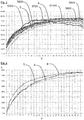
- Fig. 2 the overall efficiency ⁇ is shown as a function of the volume flow V in liters per minute.
- the curve A shows the course of a conventional arrangement with an asynchronous motor, which is operated directly from the grid, ie without frequency converter 14th
- the overall efficiency ⁇ can increase by up to about 6% compared to a conventional arrangement.
- the speed can be reduced so far that the pivot angle of the fluid pump 10 is operated at the maximum amount conveyed at the optimum pivot angle. This can be achieved, for example, by a fixed set speed, e.g. 950 revolutions per minute. Already at this point, the overall efficiency ⁇ can be increased by around 9% at this operating point.
- the curves shown represent the course for different setpoint speeds.
- the curve S500 represents a target speed of 500 revolutions per minute.
- Theylontrialsrad ⁇ is significantly increased, especially at low flow rates.
- S600 corresponds to a target speed of 600 revolutions per minute, S700 a target speed of 700 revolutions per minute, S800 a target speed of 800 revolutions per minute, S900 a target speed of 900 revolutions per minute and S1000 a target speed of 1,000 revolutions per minute.
- the curve R corresponds to the profile of the overall efficiency ⁇ , wherein the target rotational speed is determined automatically by means of a control algorithm in the control device 16.
- the actual speed values provided by the frequency converter can be used to calculate the setpoint speed.
- data from external sensors are not used to determine the respective setpoint speed.
- the target speed is in particular proportional to the output power of the drive motor 12 and the overall efficiency ⁇ . Furthermore, the target speed is inversely proportional to the operating pressure and the delivery volume of the fluid pump 10 per revolution.
- the controller 16 may determine the optimum desired speed for each part load range and automatically adjust for the corresponding volume flow V.
Landscapes
- Engineering & Computer Science (AREA)
- Mechanical Engineering (AREA)
- General Engineering & Computer Science (AREA)
- Computer Hardware Design (AREA)
- Control Of Positive-Displacement Pumps (AREA)
Abstract
Description
- Die Erfindung betrifft eine Antriebsvorrichtung für eine Fluidpumpe mit einem Förderwerk, das dazu ausgebildet ist, bei jeder Umdrehung ein Fördervolumen zu fördern, sowie ein Verfahren zum Betreiben einer Fluidpumpe. Die Antriebsvorrichtung umfasst einen Antriebsmotor zum Antreiben des Förderwerks mit einer Drehzahl.
- Es sind Verfahren bekannt, bei denen die Energieeffizienz von drehzahlvariablen Pumpen verbessert wird. Dabei kann die Drehzahl des Antriebs als Stellgröße vorgegeben werden. Die Steuerung erfolgt an der Pumpe selbst. Auch werden zur Bestimmung der Drehzahl externe Sensoren, z.B. zur Ermittlung des Volumenstroms oder des Förderdrucks, herangezogen.
- Diese Sensoren sind in der Herstellung und der Wartung vergleichsweise kostenintensiv.
- Es ist daher eine Aufgabe der Erfindung, eine Antriebsvorrichtung der eingangs genannten Art, ein System mit einer Antriebsvorrichtung und einer Fluidpumpe sowie ein Verfahren zum Betreiben einer Fluidpumpe dahingehend zu verbessern, dass auf einfache und kostengünstige Weise Energie eingespart wird.
- Die Lösung dieser Aufgabe erfolgt durch die Antriebsvorrichtung, das System sowie das Verfahren der unabhängigen Ansprüche.
- Bei der Fluidpumpe kann es sich insbesondere um eine Axialkolbenpumpe oder Radialkolbenpumpe handeln. Die Fluidpumpe kann vorzugsweise als Verstell- oder Regelpumpe ausgebildet sein, d.h. das Fördervolumen kann variiert werden. Grundsätzlich ist jedoch auch der Einsatz einer Konstantpumpe denkbar.
- Erfindungsgemäß umfasst die Antriebsvorrichtung einen Frequenzumrichter. Während herkömmliche Pumpenanordnungen häufig von unmittelbar am Netz betriebenen Asynchronmotoren betrieben werden, ist vorliegend ein Frequenzumrichter dem Antriebsmotor vorgeschaltet.
- Der Begriff Frequenzumrichter ist breit zu verstehen und umfasst jede Art von drehzahlveränderlichen Stelleinheiten.
- Die Antriebsvorrichtung umfasst eine Steuerungsvorrichtung, die dazu ausgebildet ist, ohne externe Sensoren, also sensorlos, eine Soll-Drehzahl zu bestimmen, wobei die Soll-Drehzahl einer auf den Gesamtwirkungsgrad der Antriebsvorrichtung und der Fluidpumpe optimierten Drehzahl entspricht.
- Im Gegensatz zu herkömmlichen Pumpenanordnungen wird erfindungsgemäß der Gesamtwirkungsgrad betrachtet, also von der Energiezuführung am Eingang bis zur hydraulische Leistung, z.B. Druck und Fördermenge, die am Ausgang zur Verfügung gestellt wird. Der Druck kann vorzugsweise stets aufrechterhalten werden. Im Gegensatz zu herkömmlichen Pumpenanordnungen wird der Druck also insbesondere nicht angepasst.
- Der Begriff Soll-Drehzahl ist breit zu verstehen und umfasst beispielsweise auch einen Soll-Drehzahlbereich. Die Soll-Drehzahl, also die Drehzahl, bei der der Gesamtwirkungsgrad hoch ist und somit Energie eingespart wird, kann ohne externe Sensoren wie beispielsweise Sensoren zur Bestimmung des Volumenstroms, des Förderdrucks oder des Schwenkwinkels bestimmt werden. Kosten können hierbei sowohl bei der Herstellung als auch bei der Wartung eingespart werden.
- Die Steuerungsvorrichtung steuert die Pumpe dann insbesondere mit der bestimmten Soll-Drehzahl. Es wird also gewissermaßen die Möglichkeit der Fluidpumpe im Regelbereich beschnitten, um einen hohen Wirkungsgrad zu erzielen. Die prozentuale Energieeinsparung ist dadurch beispielsweise bei hydraulischen Pressen oder Einzelaggregaten hoch.
- Weiterbildungen der Erfindung sind auch den abhängigen Ansprüchen, der Beschreibung sowie den beigefügten Zeichnungen zu entnehmen.
- Gemäß einer Ausführungsform ist die Soll-Drehzahl lediglich anhand von technischen Daten des Antriebsmotors, des Frequenzumrichters und/oder der Fluidpumpe bestimmbar. Alternativ oder zusätzlich ist die Soll-Drehzahl in einem Speicher hinterlegt.
- Die Soll-Drehzahl wird folglich insbesondere ausschließlich anhand von technische Daten errechnet bzw. anhand eines in einem Speicher hinterlegten Datensatzes bestimmt. Beispielsweise Messungen des Volumenstroms, des Förderdrucks oder des Schwenkwinkels sind für die Berechnung der Soll-Drehzahl nicht vorgesehen, grundsätzlich jedoch zusätzlich denkbar.
- Nach einer weiteren Ausführungsform umfassen die technischen Daten die Ausgangsleistung des Antriebsmotors, den Betriebsdruck der Fluidpumpe, das Fördervolumen der Fluidpumpe, die Ist-Drehzahl aus dem Frequenzumrichter und/oder das Drehmoment aus dem Frequenzumrichter, auf das reguliert wird.
- Um den besten Gesamtwirkungsgrad im jeweiligen Teillastbereich zu erhalten, kann durch Erstellen eines Steueralgorithmus in der Steuerungsvorrichtung jeweils die optimale Soll-Drehzahl errechnet werden.
- Insbesondere wird hierbei der Schwenkwinkel auch im Teillastbereich annähernd voll, d.h. mindestens 80 %, vorzugsweise wenigstens 90 %, besonderes bevorzugt zumindest 95 %, ausgeschwenkt. Dadurch kann dieser im bestmöglichen Betriebspunkt gehalten werden.
- Neben den technischen Daten der Fluidpumpe, insbesondere des Betriebsdrucks, können beispielsweise auch die vom Frequenzumrichter zur Verfügung gestellten Ist-Drehzahl-Werte zur Berechnung der Soll-Drehzahl herangezogen werden.
- Die Soll-Drehzahl ist insbesondere proportional zur Ausgangsleistung des Antriebsmotors, vorzugsweise der Leistung an der Welle, und dem Gesamtwirkungsgrad. Ferner ist die Soll-Drehzahl umgekehrt proportional zum Betriebsdruck und dem Fördervolumen der Fluidpumpe pro Umdrehung.
- Es ergibt sich somit insbesondere folgender Berechnungsansatz:
- Soll-Drehzahl ∼ Leistung an der Welle * 600.000 * Gesamtwirkungsgrad / (Betriebsdruck * Fördervolumen der Fluidpumpe pro Umdrehung).
- Die Drehzahl kann durch die Steuerungsvorrichtung für jeden Teillastbereich automatisch angepasst werden. So kann die Drehzahl z.B. verringert werden, um eine Torkelscheibe bzw. einen Schrägring einer Fluidpumpe optimal auszulenken und den Gesamtwirkungsgrad zu verbessern.
- Dies führt zu einer wesentlichen Wirkungsgraderhöhung und somit zu einer wesentlichen Steigerung der Energieeffizienz des Gesamtsystems einer Hydraulikversorgung.
- Gemäß einer weiteren Ausführungsform ist der Antriebsmotor als Reluktanzmotor oder als Synchronservomotor ausgebildet. Grundsätzlich kann z.B. auch ein Gleichstrom-, Drehstrom- oder Asynchronmotor vorgesehen sein.
- Durch die Verwendung eines Reluktanz- bzw. Synchronservomotors in Verbindung mit einem Frequenzumrichter anstelle eines Asynchronmotors, der direkt am Netz betrieben wird, ist eine Erhöhung des Gesamtwirkungsgrades im Nennbetriebspunkt von bis etwa 6 % zu erreichen, abhängig von der Optimierung des Frequenzumrichters. Zudem werden bei einer derartigen Anordnung aus Reluktanz- bzw. Synchronservomotor, Frequenzumrichter und Axial- bzw. Radialkolbenpumpe der Anlaufstrom und die vom Netz geforderte Blindleistung wesentlich reduziert. Für ein System aus Reluktanz- bzw. Synchronservomotor, Frequenzumrichter und Axial- bzw. Radialkolbenpumpe wird auch unabhängig Schutz beansprucht.
- Nach einer weiteren Ausführungsform weist der Frequenzumrichter die Steuerungsvorrichtung auf. Während sich herkömmliche Fluidpumpen selbst regeln, ist die Steuerungsvorrichtung nicht in der Fluidpumpe angeordnet. Auch bestehende Fluidpumpen können dadurch auf einfache Weise nachgerüstet werden, da lediglich ein Frequenzumrichter mit einer entsprechenden Steuerungsvorrichtung vorgeschaltet werden muss. Alternativ kann die Steuerungsvorrichtung auch als separates Bauteil ausgebildet sein.
- Gemäß einer weiteren Ausführungsform ist die Steuerungsvorrichtung dazu ausgebildet, für jeden Teillastbereich eine Soll-Drehzahl zu bestimmen. Die Drehzahl kann somit für jeden Teillastbereich automatisch angepasst werden, wodurch für den jeweiligen Teillastbereich der beste Gesamtwirkungsgrad erreicht wird.
- Nach einer weiteren Ausführungsform umfasst die Steuerungsvorrichtung einen Speicher oder hat Zugriff auf einen Speicher, in dem ein Datensatz hinterlegt ist. Vorzugsweise kann der Datensatz z.B. in Form einer Tabelle, eines Polygonzugs oder eines Kennfelds hinterlegt sein. Der Datensatz umfasst Soll-Drehzahlen in Abhängigkeit von Drehmomenten aus dem Frequenzumrichter, auf die reguliert wird.
- Zur Erstellung des Datensatzes können z.B. der Start und das Ende gemessen bzw. empirisch bestimmt werden. So kann die Anlage beispielsweise mit einer Mindestdrehzahl und einer überhöhten Drehzahl gefahren werden. Zwischen den gemessenen bzw. empirisch bestimmten Daten kann interpoliert werden.
- Die Steuerungsvorrichtung wählt aus dem Datensatz das Drehmoment aus dem Frequenzumrichter, auf das reguliert wird, aus und ermittelt im Datensatz die entsprechende Soll-Drehzahl, mit der die Fluidpumpe betrieben werden soll.
- Die Erfindung betrifft auch ein System mit einer erfindungsgemäßen Antriebsvorrichtung und einer Fluidpumpe. Es können einerseits bestehende Fluidpumpen mit einer Antriebsvorrichtung nachgerüstet und andererseits neue Gesamtsysteme hergestellt werden.
- Gemäß einer Ausführungsform ist die Fluidpumpe als Axialkolbenpumpe oder Radialkolbenpumpe ausgebildet.
- Ferner betrifft die Erfindung ein Verfahren zum Betreiben einer Fluidpumpe mit einer erfindungsgemäßen Antriebsvorrichtung, bei dem ohne externe Sensoren, also sensorlos, eine Soll-Drehzahl bestimmt wird, wobei die Soll-Drehzahl einer auf den Gesamtwirkungsgrad der Antriebsvorrichtung und der Fluidpumpe optimierten Drehzahl entspricht.
- Insbesondere wird die Fluidpumpe dann mit der entsprechenden Soll-Drehzahl betrieben. So kann im Teillastbereich der Fluidpumpe durch Ermitteln des Lastprofils die Drehzahl soweit verringert werden, dass der Schwenkwinkel der Fluidpumpe bei maximal geförderter Menge im optimalen Schwenkwinkel betrieben wird. Dies kann beispielsweise durch eine fest eingestellte Soll-Drehzahl erreicht werden, z.B. 950 Umdrehungen pro Minute. Bereits dadurch lässt sich in diesem Betriebspunkt der Gesamtwirkungsgrad um rund 9 % erhöhen.
- Neben dieser manuellen Verringerung der Drehzahl kann die Drehzahl auch automatisiert angepasst werden. So kann die Drehzahl entsprechend angepasst werden, um im jeweiligen Teillastbereich automatisch den besten Gesamtwirkungsgrad zu erhalten. Dabei kann auf einen Steuerungsalgorithmus zurückgegriffen werden. Steigerungen des Gesamtwirkungsgrads um rund 10 % sind dadurch möglich.
- Alle hier beschriebenen Ausführungsformen der Vorrichtung sowie des Systems sind insbesondere dazu ausgebildet, nach dem hier beschriebenen Verfahren betrieben zu werden. Ferner können alle hier beschriebenen Ausführungsformen der Vorrichtung bzw. des Systems sowie alle hier beschriebenen Ausführungsformen des Verfahrens jeweils miteinander kombiniert werden, insbesondere auch losgelöst von der konkreten Ausgestaltung, in deren Zusammenhang sie erwähnt werden.
- Die Erfindung wird im Folgenden beispielhaft unter Bezugnahme auf die Zeichnungen beschrieben. Es zeigen:
- Fig. 1
- eine schematische Darstellung einer Ausführungsform eines erfindungsgemäßen Systems,
- Fig. 2
- den Wirkungsgradverlauf in Abhängigkeit vom Volumenstrom bei einem erfindungsgemäßen System,
- Fig. 3
- den Wirkungsgradverlauf in Abhängigkeit vom Volumenstrom bei einem erfindungsgemäßen System bei optimierter, manueller Drehzahlanpassung, und
- Fig. 4
- den Wirkungsgradverlauf in Abhängigkeit vom Volumenstrom bei einem erfindungsgemäßen System bei optimierter, automatisierter Drehzahlanpassung.
- Zunächst ist zu bemerken, dass die dargestellten Ausführungsformen rein beispielhafter Natur sind. Die Merkmale einer Ausführungsform können auch beliebig mit Merkmalen einer anderen Ausführungsform kombiniert werden.
-
Fig. 1 zeigt eine Fluidpumpe 10, z.B. eine Axialkolben- oder Radialkolbenpumpe, sowie einen Antriebsmotor 12, beispielsweise einen Reluktanz- oder Synchronservomotor, welcher die Fluidpumpe 10 mit einer bestimmten Drehzahl antreibt. - Die Drehzahl, mit der die Fluidpumpe 10 gesteuert wird, ist grundsätzlich beliebig. Diese kann z.B. im Bereich von 300 bis 3.000 Umdrehungen pro Minute, insbesondere 500 bis 1.500 Umdrehungen pro Minute, liegen.
- Über einen Frequenzumrichter 14, welcher eine Steuerungsvorrichtung 16 umfasst, kann eine Soll-Drehzahl bestimmt werden. Der Antriebsmotor 12 kann mit der Soll-Drehzahl betrieben werden, um einen Gesamtwirkungsgrad η der Anordnung zu erhöhen.
- In
Fig. 2 ist der Gesamtwirkungsgrad η in Abhängigkeit vom Volumenstrom V in Liter pro Minute dargestellt. Die Kurve A zeigt den Verlauf einer herkömmlichen Anordnung mit einem Asynchronmotor, welcher direkt aus dem Netz betrieben wird, d.h. ohne Frequenzumrichter 14. - Der höchste Wirkungsgrad η stellt sich hierbei erst bei relativ hohen Volumenströmen von etwa 95 % ihres Nennvolumens ein. Fluidpumpen 10 werden jedoch meist mit Volumenströmen zwischen etwa 20 und 80 % ihres Nennvolumens betrieben.
- Durch die Verwendung einer Anordnung mit einer Axialkolben- bzw. Radialkolbenpumpe 10, einem Reluktanz- oder Synchronservomotor 12 sowie einem Frequenzumrichter 14 kann je nach Optimierung des Frequenzumrichters 14 eine erhebliche Steigerung des Gesamtwirkungsgrads η erreicht werden, wie durch die Kurve S ersichtlich ist. Auch im normalen Betriebsbereich mit Volumenströmen zwischen etwa 20 und 80 % ihres Nennvolumens ist eine deutliche Erhöhung des Gesamtwirkungsgrads η ersichtlich.
- Der Gesamtwirkungsgrads η kann sich im Vergleich zu einer herkömmlichen Anordnung um bis ca. 6 % erhöhen.
- In
Fig. 3 ist der Gesamtwirkungsgrad η in Abhängigkeit vom Volumenstrom V in Liter pro Minute dargestellt. Als Referenz sind abermals die die Kurven A und S dargestellt. - Im Teillastbereich der Fluidpumpe 10 kann durch Ermitteln des Lastprofils die Drehzahl soweit verringert werden, dass der Schwenkwinkel der Fluidpumpe 10 bei maximal geförderter Menge im optimalen Schwenkwinkel betrieben wird. Dies kann beispielsweise durch eine fest eingestellte Soll-Drehzahl erreicht werden, z.B. 950 Umdrehungen pro Minute. Bereits dadurch lässt sich in diesem Betriebspunkt der Gesamtwirkungsgrad η um rund 9 % erhöhen.
- Die dargestellten Kurven geben den Verlauf für verschiedene Soll-Drehzahlen wieder. So repräsentiert die Kurve S500 eine Soll-Drehzahl von 500 Umdrehungen pro Minute. Der Gesamtwirkungsrad η wird dabei gerade bei niedrigen Volumenströmen deutlich erhöht. S600 entspricht einer Soll-Drehzahl von 600 Umdrehungen pro Minute, S700 einer Soll-Drehzahl von 700 Umdrehungen pro Minute, S800 einer Soll-Drehzahl von 800 Umdrehungen pro Minute, S900 einer Soll-Drehzahl von 900 Umdrehungen pro Minute und S1000 einer Soll-Drehzahl von 1.000 Umdrehungen pro Minute.
- Je höher die Soll-Drehzahl, desto weiter nach rechts, also in Richtung höherer Volumenströme V, verschiebt sich der maximale Gesamtwirkungsgrad η.
- In
Fig. 4 ist der Gesamtwirkungsgrad η in Abhängigkeit vom Volumenstrom V in Liter pro Minute dargestellt. Als Referenz sind abermals die die Kurven A und S dargestellt. - Die Kurve R entspricht dem Verlauf des Gesamtwirkungsgrads η, wobei die Soll-Drehzahl automatisch mithilfe eines Steuerungs- bzw. Regelalgorithmus in der Steuerungsvorrichtung 16 bestimmt wird.
- Neben den technischen Daten der Fluidpumpe, insbesondere des Betriebsdrucks, können beispielsweise auch die vom Frequenzumrichter zur Verfügung gestellten Ist-Drehzahl-Werte zur Berechnung der Soll-Drehzahl herangezogen werden. Daten aus externen Sensoren werden hingegen nicht verwendet, um die jeweilige Soll-Drehzahl zu bestimmen.
- Die Soll-Drehzahl ist insbesondere proportional zur Ausgangsleistung des Antriebsmotors12 und dem Gesamtwirkungsgrad η. Ferner ist die Soll-Drehzahl umgekehrt proportional zum Betriebsdruck und dem Fördervolumen der Fluidpumpe 10 pro Umdrehung.
- Soll-Drehzahl ∼ Leistung an der Welle * 600.000 * Gesamtwirkungsgrad / (Betriebsdruck * Fördervolumen der Fluidpumpe pro Umdrehung) kann die Steuerungsvorrichtung 16 für jeden Teillastbereich die optimale Soll-Drehzahl bestimmen und für den entsprechenden Volumenstrom V automatisch anpassen.
- Dies führt im gesamten Teillastbereich zu einer erheblichen Verbesserung des Gesamtwirkungsgrad η. So sind Steigerungen von etwa 10 % erreichbar.
-
- 10
- Fluidpumpe, Axialkolbenpumpe, Radialkolbenpumpe
- 12
- Antriebsmotor, Reluktanzmotor, Synchronservomotor
- 14
- Frequenzumrichter
- 16
- Steuerungsvorrichtung
- η
- Gesamtwirkungsgrad
- V
- Volumenstrom
- A
- Verlauf bei Asynchronmotor ohne Frequenzumrichter
- S
- Verlauf bei Synchronservomotor mit Frequenzumrichter
- S500
- Verlauf bei Soll-Drehzahl von 500 Umdrehungen pro Minute
- S600
- Verlauf bei Soll-Drehzahl von 600 Umdrehungen pro Minute
- S700
- Verlauf bei Soll-Drehzahl von 700 Umdrehungen pro Minute
- S800
- Verlauf bei Soll-Drehzahl von 800 Umdrehungen pro Minute
- S900
- Verlauf bei Soll-Drehzahl von 900 Umdrehungen pro Minute
- S1000
- Verlauf bei Soll-Drehzahl von 1000 Umdrehungen pro Minute
- R
- Verlauf bei automatisierter Anpassung der Soll-Drehzahl
Claims (10)
- Antriebsvorrichtung für eine Fluidpumpe (10), insbesondere Axialkolbenpumpe oder Radialkolbenpumpe, mit einem Förderwerk, das dazu ausgebildet ist, bei jeder Umdrehung ein Fördervolumen zu fördern, umfassend einen Antriebsmotor (12) zum Antreiben des Förderwerks mit einer Drehzahl,
einen Frequenzumrichter (14), und
eine Steuerungsvorrichtung (16), die dazu ausgebildet ist, ohne externe Sensoren eine Soll-Drehzahl zu bestimmen, wobei die Soll-Drehzahl einer auf den Gesamtwirkungsgrad der Antriebsvorrichtung und der Fluidpumpe (10) optimierten Drehzahl entspricht. - Antriebsvorrichtung nach Anspruch 1,
dadurch gekennzeichnet,
dass die Soll-Drehzahl lediglich anhand von technischen Daten des Antriebsmotors (12), des Frequenzumrichters (14) und/oder der Fluidpumpe (10) bestimmbar und/oder in einem Speicher hinterlegt ist. - Antriebsvorrichtung nach Anspruch 2,
dadurch gekennzeichnet,
dass die technischen Daten die Ausgangsleistung des Antriebsmotors (12), den Betriebsdruck der Fluidpumpe (10), das Fördervolumen der Fluidpumpe (10), die Ist-Drehzahl aus dem Frequenzumrichter (14) und/oder das Drehmoment aus dem Frequenzumrichter (14), auf das reguliert wird, umfassen. - Antriebsvorrichtung nach einem der vorhergehenden Ansprüche,
dadurch gekennzeichnet,
dass der Antriebsmotor (12) als Reluktanzmotor oder als Synchronservomotor ausgebildet ist. - Antriebsvorrichtung nach einem der vorhergehenden Ansprüche,
dadurch gekennzeichnet,
dass der Frequenzumrichter (14) die Steuerungsvorrichtung (16) aufweist. - Antriebsvorrichtung nach einem der vorhergehenden Ansprüche,
dadurch gekennzeichnet,
dass die Steuerungsvorrichtung (16) dazu ausgebildet ist, für jeden Teillastbereich eine Soll-Drehzahl zu bestimmen. - Antriebsvorrichtung nach einem der vorhergehenden Ansprüche,
dadurch gekennzeichnet,
dass die Steuerungsvorrichtung (16) einen Speicher umfasst oder Zugriff auf einen Speicher hat, in dem ein Datensatz, insbesondere Polygonzug, hinterlegt ist, welcher Soll-Drehzahlen in Abhängigkeit von Drehmomenten aus dem Frequenzumrichter (14), auf die reguliert wird, umfasst. - System mit einer Antriebsvorrichtung nach einem der vorhergehenden Ansprüche und einer Fluidpumpe (10) mit einem Förderwerk, das dazu ausgebildet ist, bei jeder Umdrehung ein Fördervolumen zu fördern.
- System nach Anspruch 8,
dadurch gekennzeichnet,
dass die Fluidpumpe (10) als Axialkolbenpumpe oder Radialkolbenpumpe ausgebildet ist. - Verfahren zum Betreiben einer Fluidpumpe (10) mit einer Antriebsvorrichtung nach einem der Ansprüche 1 bis 7, bei dem ohne externe Sensoren eine Soll-Drehzahl bestimmt wird, wobei die Soll-Drehzahl einer auf den Gesamtwirkungsgrad der Antriebsvorrichtung und der Fluidpumpe (10) optimierten Drehzahl entspricht.
Applications Claiming Priority (1)
| Application Number | Priority Date | Filing Date | Title |
|---|---|---|---|
| DE102016125837.7A DE102016125837A1 (de) | 2016-12-29 | 2016-12-29 | Antriebsvorrichtung für eine Fluidpumpe |
Publications (2)
| Publication Number | Publication Date |
|---|---|
| EP3343032A1 true EP3343032A1 (de) | 2018-07-04 |
| EP3343032B1 EP3343032B1 (de) | 2020-04-01 |
Family
ID=60856906
Family Applications (1)
| Application Number | Title | Priority Date | Filing Date |
|---|---|---|---|
| EP17210615.5A Active EP3343032B1 (de) | 2016-12-29 | 2017-12-27 | Antriebsvorrichtung für eine fluidpumpe |
Country Status (2)
| Country | Link |
|---|---|
| EP (1) | EP3343032B1 (de) |
| DE (1) | DE102016125837A1 (de) |
Families Citing this family (1)
| Publication number | Priority date | Publication date | Assignee | Title |
|---|---|---|---|---|
| DE102023210639A1 (de) * | 2023-10-27 | 2025-04-30 | Robert Bosch Gesellschaft mit beschränkter Haftung | Verfahren zur Bestimmung einer optimalen Drehzahl einer Druckmittelversorgungseinrichtung eines elektrohydraulischen Systems |
Citations (3)
| Publication number | Priority date | Publication date | Assignee | Title |
|---|---|---|---|---|
| DE19630384A1 (de) * | 1996-07-29 | 1998-04-23 | Becker Kg Gebr | Verfahren zur Steuerung oder Regelung eines Aggregats und Frequenzumwandler |
| DE102011050017A1 (de) * | 2011-04-29 | 2012-10-31 | Allweiler Gmbh | Steuermittel zum Ansteuern eines Frequenzumrichters sowie Ansteuerverfahren |
| DE102012016780A1 (de) * | 2012-06-01 | 2013-12-05 | Robert Bosch Gmbh | Verfahren zum Betreiben einer Fluidpumpe |
Family Cites Families (2)
| Publication number | Priority date | Publication date | Assignee | Title |
|---|---|---|---|---|
| CN101033748B (zh) * | 2006-03-08 | 2013-07-24 | Itt制造企业公司 | 不使用传统传感器的确定泵流量的方法 |
| DE102014004336A1 (de) * | 2014-03-26 | 2015-10-01 | Wilo Se | Verfahren zur Bestimmung des hydraulischen Arbeitspunktes eines Pumpenaggregats |
-
2016
- 2016-12-29 DE DE102016125837.7A patent/DE102016125837A1/de active Pending
-
2017
- 2017-12-27 EP EP17210615.5A patent/EP3343032B1/de active Active
Patent Citations (3)
| Publication number | Priority date | Publication date | Assignee | Title |
|---|---|---|---|---|
| DE19630384A1 (de) * | 1996-07-29 | 1998-04-23 | Becker Kg Gebr | Verfahren zur Steuerung oder Regelung eines Aggregats und Frequenzumwandler |
| DE102011050017A1 (de) * | 2011-04-29 | 2012-10-31 | Allweiler Gmbh | Steuermittel zum Ansteuern eines Frequenzumrichters sowie Ansteuerverfahren |
| DE102012016780A1 (de) * | 2012-06-01 | 2013-12-05 | Robert Bosch Gmbh | Verfahren zum Betreiben einer Fluidpumpe |
Also Published As
| Publication number | Publication date |
|---|---|
| EP3343032B1 (de) | 2020-04-01 |
| DE102016125837A1 (de) | 2018-07-05 |
Similar Documents
| Publication | Publication Date | Title |
|---|---|---|
| DE202016107468U1 (de) | Antriebsvorrichtung für eine Fluidpumpe | |
| EP2328747B1 (de) | Druckspeicherlose hydraulische antriebsanordnung für und mit einem verbraucher, insbesondere für hydraulische pressen, sowie verfahren zum druckspeicherlosen hydraulischen antreiben eines verbrauchers | |
| EP2597310B1 (de) | Verfahren zum Betreiben einer drehzahlvariablen Verstellpumpe | |
| DE102015209074B3 (de) | Vorrichtung und verfahren zum steuern einer hydraulikmaschine | |
| DE102012016780B4 (de) | Verfahren zum Betreiben einer Fluidpumpe | |
| DE2059314C3 (de) | Brennstoffzufuhranlage für ein Gasturbinentriebwerk | |
| EP2940309B1 (de) | Verfahren zur Regelung eines Pumpensystems und geregeltes Pumpensystem | |
| AT515590B1 (de) | Dynamischer Sollwertausgleich bei drehzahlvariablen Verstellpumpen | |
| DE112009000113T5 (de) | Vorrichtung und Verfahren zur Motorsteuerung | |
| DE102012009136A1 (de) | Verfahren zum Betreiben einer Fluidpumpe | |
| EP3167197B1 (de) | Verfahren zur druck- und temperaturreglung eines fluids in einer serie von kryogenen verdichtern | |
| EP3988801B1 (de) | Verfahren zum betreiben eines hydraulischen antriebs | |
| WO2011131286A1 (de) | Verfahren zur begrenzung eines drucks in einem hydrostatischen getriebe | |
| EP3388677A1 (de) | Verfahren zur steuerung eines schraubenverdichters | |
| EP3343032A1 (de) | Antriebsvorrichtung für eine fluidpumpe | |
| DE102016011778A1 (de) | Hydraulische, insbesondere druckspeicherlose, Antriebsanordnung für und mit einem Verbraucher, insbesondere für Pressen, sowie Verfahren zum Betreiben einer solchen hydraulischen Antriebsanordnung | |
| DE102006040970B4 (de) | Verfahren zum Betrieb einer Windenergieanlage | |
| EP2584192A1 (de) | Pitchverstelleinrichtung | |
| EP1614903B1 (de) | Antriebsbaueinheit für eine Kreiselpumpe | |
| WO2007147380A1 (de) | Axialpumpe | |
| EP4253754B1 (de) | Verfahren zum betreiben einer drehzahlvariablen pumpe | |
| WO2012038050A1 (de) | Hydromaschine mit elektronisch gesteuerten ventilen | |
| DE102009025707A1 (de) | Vorrichtung zur Steuerung einer Anlage mit Hydraulikkreisen | |
| EP4720520A1 (de) | Verfahren zum betrieb einer mehrpumpenanlage mit wenigstens zwei hydraulisch parallel betreibbaren pumpen sowie mehrpumpenanlage | |
| EP4134185B1 (de) | Hydraulikantrieb für die oszillation einer kokille einer stranggiessmaschine |
Legal Events
| Date | Code | Title | Description |
|---|---|---|---|
| PUAI | Public reference made under article 153(3) epc to a published international application that has entered the european phase |
Free format text: ORIGINAL CODE: 0009012 |
|
| STAA | Information on the status of an ep patent application or granted ep patent |
Free format text: STATUS: REQUEST FOR EXAMINATION WAS MADE |
|
| 17P | Request for examination filed |
Effective date: 20180115 |
|
| AK | Designated contracting states |
Kind code of ref document: A1 Designated state(s): AL AT BE BG CH CY CZ DE DK EE ES FI FR GB GR HR HU IE IS IT LI LT LU LV MC MK MT NL NO PL PT RO RS SE SI SK SM TR |
|
| AX | Request for extension of the european patent |
Extension state: BA ME |
|
| GRAP | Despatch of communication of intention to grant a patent |
Free format text: ORIGINAL CODE: EPIDOSNIGR1 |
|
| STAA | Information on the status of an ep patent application or granted ep patent |
Free format text: STATUS: GRANT OF PATENT IS INTENDED |
|
| INTG | Intention to grant announced |
Effective date: 20191121 |
|
| GRAS | Grant fee paid |
Free format text: ORIGINAL CODE: EPIDOSNIGR3 |
|
| GRAA | (expected) grant |
Free format text: ORIGINAL CODE: 0009210 |
|
| STAA | Information on the status of an ep patent application or granted ep patent |
Free format text: STATUS: THE PATENT HAS BEEN GRANTED |
|
| AK | Designated contracting states |
Kind code of ref document: B1 Designated state(s): AL AT BE BG CH CY CZ DE DK EE ES FI FR GB GR HR HU IE IS IT LI LT LU LV MC MK MT NL NO PL PT RO RS SE SI SK SM TR |
|
| REG | Reference to a national code |
Ref country code: GB Ref legal event code: FG4D Free format text: NOT ENGLISH |
|
| REG | Reference to a national code |
Ref country code: AT Ref legal event code: REF Ref document number: 1251672 Country of ref document: AT Kind code of ref document: T Effective date: 20200415 Ref country code: CH Ref legal event code: EP |
|
| REG | Reference to a national code |
Ref country code: DE Ref legal event code: R096 Ref document number: 502017004473 Country of ref document: DE |
|
| REG | Reference to a national code |
Ref country code: IE Ref legal event code: FG4D Free format text: LANGUAGE OF EP DOCUMENT: GERMAN |
|
| PG25 | Lapsed in a contracting state [announced via postgrant information from national office to epo] |
Ref country code: BG Free format text: LAPSE BECAUSE OF FAILURE TO SUBMIT A TRANSLATION OF THE DESCRIPTION OR TO PAY THE FEE WITHIN THE PRESCRIBED TIME-LIMIT Effective date: 20200701 |
|
| REG | Reference to a national code |
Ref country code: NL Ref legal event code: MP Effective date: 20200401 |
|
| REG | Reference to a national code |
Ref country code: LT Ref legal event code: MG4D |
|
| PG25 | Lapsed in a contracting state [announced via postgrant information from national office to epo] |
Ref country code: IS Free format text: LAPSE BECAUSE OF FAILURE TO SUBMIT A TRANSLATION OF THE DESCRIPTION OR TO PAY THE FEE WITHIN THE PRESCRIBED TIME-LIMIT Effective date: 20200801 Ref country code: CZ Free format text: LAPSE BECAUSE OF FAILURE TO SUBMIT A TRANSLATION OF THE DESCRIPTION OR TO PAY THE FEE WITHIN THE PRESCRIBED TIME-LIMIT Effective date: 20200401 Ref country code: GR Free format text: LAPSE BECAUSE OF FAILURE TO SUBMIT A TRANSLATION OF THE DESCRIPTION OR TO PAY THE FEE WITHIN THE PRESCRIBED TIME-LIMIT Effective date: 20200702 Ref country code: SE Free format text: LAPSE BECAUSE OF FAILURE TO SUBMIT A TRANSLATION OF THE DESCRIPTION OR TO PAY THE FEE WITHIN THE PRESCRIBED TIME-LIMIT Effective date: 20200401 Ref country code: NO Free format text: LAPSE BECAUSE OF FAILURE TO SUBMIT A TRANSLATION OF THE DESCRIPTION OR TO PAY THE FEE WITHIN THE PRESCRIBED TIME-LIMIT Effective date: 20200701 Ref country code: FI Free format text: LAPSE BECAUSE OF FAILURE TO SUBMIT A TRANSLATION OF THE DESCRIPTION OR TO PAY THE FEE WITHIN THE PRESCRIBED TIME-LIMIT Effective date: 20200401 Ref country code: LT Free format text: LAPSE BECAUSE OF FAILURE TO SUBMIT A TRANSLATION OF THE DESCRIPTION OR TO PAY THE FEE WITHIN THE PRESCRIBED TIME-LIMIT Effective date: 20200401 Ref country code: PT Free format text: LAPSE BECAUSE OF FAILURE TO SUBMIT A TRANSLATION OF THE DESCRIPTION OR TO PAY THE FEE WITHIN THE PRESCRIBED TIME-LIMIT Effective date: 20200817 Ref country code: NL Free format text: LAPSE BECAUSE OF FAILURE TO SUBMIT A TRANSLATION OF THE DESCRIPTION OR TO PAY THE FEE WITHIN THE PRESCRIBED TIME-LIMIT Effective date: 20200401 |
|
| PG25 | Lapsed in a contracting state [announced via postgrant information from national office to epo] |
Ref country code: HR Free format text: LAPSE BECAUSE OF FAILURE TO SUBMIT A TRANSLATION OF THE DESCRIPTION OR TO PAY THE FEE WITHIN THE PRESCRIBED TIME-LIMIT Effective date: 20200401 Ref country code: RS Free format text: LAPSE BECAUSE OF FAILURE TO SUBMIT A TRANSLATION OF THE DESCRIPTION OR TO PAY THE FEE WITHIN THE PRESCRIBED TIME-LIMIT Effective date: 20200401 Ref country code: LV Free format text: LAPSE BECAUSE OF FAILURE TO SUBMIT A TRANSLATION OF THE DESCRIPTION OR TO PAY THE FEE WITHIN THE PRESCRIBED TIME-LIMIT Effective date: 20200401 |
|
| PG25 | Lapsed in a contracting state [announced via postgrant information from national office to epo] |
Ref country code: AL Free format text: LAPSE BECAUSE OF FAILURE TO SUBMIT A TRANSLATION OF THE DESCRIPTION OR TO PAY THE FEE WITHIN THE PRESCRIBED TIME-LIMIT Effective date: 20200401 |
|
| REG | Reference to a national code |
Ref country code: DE Ref legal event code: R097 Ref document number: 502017004473 Country of ref document: DE |
|
| PG25 | Lapsed in a contracting state [announced via postgrant information from national office to epo] |
Ref country code: RO Free format text: LAPSE BECAUSE OF FAILURE TO SUBMIT A TRANSLATION OF THE DESCRIPTION OR TO PAY THE FEE WITHIN THE PRESCRIBED TIME-LIMIT Effective date: 20200401 Ref country code: ES Free format text: LAPSE BECAUSE OF FAILURE TO SUBMIT A TRANSLATION OF THE DESCRIPTION OR TO PAY THE FEE WITHIN THE PRESCRIBED TIME-LIMIT Effective date: 20200401 Ref country code: DK Free format text: LAPSE BECAUSE OF FAILURE TO SUBMIT A TRANSLATION OF THE DESCRIPTION OR TO PAY THE FEE WITHIN THE PRESCRIBED TIME-LIMIT Effective date: 20200401 Ref country code: SM Free format text: LAPSE BECAUSE OF FAILURE TO SUBMIT A TRANSLATION OF THE DESCRIPTION OR TO PAY THE FEE WITHIN THE PRESCRIBED TIME-LIMIT Effective date: 20200401 Ref country code: EE Free format text: LAPSE BECAUSE OF FAILURE TO SUBMIT A TRANSLATION OF THE DESCRIPTION OR TO PAY THE FEE WITHIN THE PRESCRIBED TIME-LIMIT Effective date: 20200401 Ref country code: IT Free format text: LAPSE BECAUSE OF FAILURE TO SUBMIT A TRANSLATION OF THE DESCRIPTION OR TO PAY THE FEE WITHIN THE PRESCRIBED TIME-LIMIT Effective date: 20200401 |
|
| PLBE | No opposition filed within time limit |
Free format text: ORIGINAL CODE: 0009261 |
|
| STAA | Information on the status of an ep patent application or granted ep patent |
Free format text: STATUS: NO OPPOSITION FILED WITHIN TIME LIMIT |
|
| PG25 | Lapsed in a contracting state [announced via postgrant information from national office to epo] |
Ref country code: PL Free format text: LAPSE BECAUSE OF FAILURE TO SUBMIT A TRANSLATION OF THE DESCRIPTION OR TO PAY THE FEE WITHIN THE PRESCRIBED TIME-LIMIT Effective date: 20200401 Ref country code: SK Free format text: LAPSE BECAUSE OF FAILURE TO SUBMIT A TRANSLATION OF THE DESCRIPTION OR TO PAY THE FEE WITHIN THE PRESCRIBED TIME-LIMIT Effective date: 20200401 |
|
| 26N | No opposition filed |
Effective date: 20210112 |
|
| PG25 | Lapsed in a contracting state [announced via postgrant information from national office to epo] |
Ref country code: SI Free format text: LAPSE BECAUSE OF FAILURE TO SUBMIT A TRANSLATION OF THE DESCRIPTION OR TO PAY THE FEE WITHIN THE PRESCRIBED TIME-LIMIT Effective date: 20200401 |
|
| REG | Reference to a national code |
Ref country code: CH Ref legal event code: PL |
|
| PG25 | Lapsed in a contracting state [announced via postgrant information from national office to epo] |
Ref country code: MC Free format text: LAPSE BECAUSE OF FAILURE TO SUBMIT A TRANSLATION OF THE DESCRIPTION OR TO PAY THE FEE WITHIN THE PRESCRIBED TIME-LIMIT Effective date: 20200401 |
|
| REG | Reference to a national code |
Ref country code: BE Ref legal event code: MM Effective date: 20201231 |
|
| PG25 | Lapsed in a contracting state [announced via postgrant information from national office to epo] |
Ref country code: IE Free format text: LAPSE BECAUSE OF NON-PAYMENT OF DUE FEES Effective date: 20201227 Ref country code: LU Free format text: LAPSE BECAUSE OF NON-PAYMENT OF DUE FEES Effective date: 20201227 |
|
| PG25 | Lapsed in a contracting state [announced via postgrant information from national office to epo] |
Ref country code: CH Free format text: LAPSE BECAUSE OF NON-PAYMENT OF DUE FEES Effective date: 20201231 Ref country code: LI Free format text: LAPSE BECAUSE OF NON-PAYMENT OF DUE FEES Effective date: 20201231 |
|
| PGFP | Annual fee paid to national office [announced via postgrant information from national office to epo] |
Ref country code: GB Payment date: 20211124 Year of fee payment: 5 Ref country code: FR Payment date: 20211119 Year of fee payment: 5 |
|
| PG25 | Lapsed in a contracting state [announced via postgrant information from national office to epo] |
Ref country code: TR Free format text: LAPSE BECAUSE OF FAILURE TO SUBMIT A TRANSLATION OF THE DESCRIPTION OR TO PAY THE FEE WITHIN THE PRESCRIBED TIME-LIMIT Effective date: 20200401 Ref country code: MT Free format text: LAPSE BECAUSE OF FAILURE TO SUBMIT A TRANSLATION OF THE DESCRIPTION OR TO PAY THE FEE WITHIN THE PRESCRIBED TIME-LIMIT Effective date: 20200401 Ref country code: CY Free format text: LAPSE BECAUSE OF FAILURE TO SUBMIT A TRANSLATION OF THE DESCRIPTION OR TO PAY THE FEE WITHIN THE PRESCRIBED TIME-LIMIT Effective date: 20200401 |
|
| PG25 | Lapsed in a contracting state [announced via postgrant information from national office to epo] |
Ref country code: MK Free format text: LAPSE BECAUSE OF FAILURE TO SUBMIT A TRANSLATION OF THE DESCRIPTION OR TO PAY THE FEE WITHIN THE PRESCRIBED TIME-LIMIT Effective date: 20200401 |
|
| PG25 | Lapsed in a contracting state [announced via postgrant information from national office to epo] |
Ref country code: BE Free format text: LAPSE BECAUSE OF NON-PAYMENT OF DUE FEES Effective date: 20201231 |
|
| P01 | Opt-out of the competence of the unified patent court (upc) registered |
Effective date: 20230601 |
|
| GBPC | Gb: european patent ceased through non-payment of renewal fee |
Effective date: 20221227 |
|
| PG25 | Lapsed in a contracting state [announced via postgrant information from national office to epo] |
Ref country code: GB Free format text: LAPSE BECAUSE OF NON-PAYMENT OF DUE FEES Effective date: 20221227 |
|
| PG25 | Lapsed in a contracting state [announced via postgrant information from national office to epo] |
Ref country code: FR Free format text: LAPSE BECAUSE OF NON-PAYMENT OF DUE FEES Effective date: 20221231 |
|
| PGFP | Annual fee paid to national office [announced via postgrant information from national office to epo] |
Ref country code: DE Payment date: 20251103 Year of fee payment: 9 |
|
| PGFP | Annual fee paid to national office [announced via postgrant information from national office to epo] |
Ref country code: AT Payment date: 20251103 Year of fee payment: 9 |