EP3343098B1 - Lampe à diodes électroluminescentes à effet de dissipation de chaleur - Google Patents
Lampe à diodes électroluminescentes à effet de dissipation de chaleur Download PDFInfo
- Publication number
- EP3343098B1 EP3343098B1 EP18164133.3A EP18164133A EP3343098B1 EP 3343098 B1 EP3343098 B1 EP 3343098B1 EP 18164133 A EP18164133 A EP 18164133A EP 3343098 B1 EP3343098 B1 EP 3343098B1
- Authority
- EP
- European Patent Office
- Prior art keywords
- light
- tube
- heat
- led
- led lamp
- Prior art date
- Legal status (The legal status is an assumption and is not a legal conclusion. Google has not performed a legal analysis and makes no representation as to the accuracy of the status listed.)
- Active
Links
Images







Classifications
-
- F—MECHANICAL ENGINEERING; LIGHTING; HEATING; WEAPONS; BLASTING
- F21—LIGHTING
- F21K—NON-ELECTRIC LIGHT SOURCES USING LUMINESCENCE; LIGHT SOURCES USING ELECTROCHEMILUMINESCENCE; LIGHT SOURCES USING CHARGES OF COMBUSTIBLE MATERIAL; LIGHT SOURCES USING SEMICONDUCTOR DEVICES AS LIGHT-GENERATING ELEMENTS; LIGHT SOURCES NOT OTHERWISE PROVIDED FOR
- F21K9/00—Light sources using semiconductor devices as light-generating elements, e.g. using light-emitting diodes [LED] or lasers
- F21K9/20—Light sources comprising attachment means
- F21K9/23—Retrofit light sources for lighting devices with a single fitting for each light source, e.g. for substitution of incandescent lamps with bayonet or threaded fittings
- F21K9/232—Retrofit light sources for lighting devices with a single fitting for each light source, e.g. for substitution of incandescent lamps with bayonet or threaded fittings specially adapted for generating an essentially omnidirectional light distribution, e.g. with a glass bulb
-
- F—MECHANICAL ENGINEERING; LIGHTING; HEATING; WEAPONS; BLASTING
- F21—LIGHTING
- F21K—NON-ELECTRIC LIGHT SOURCES USING LUMINESCENCE; LIGHT SOURCES USING ELECTROCHEMILUMINESCENCE; LIGHT SOURCES USING CHARGES OF COMBUSTIBLE MATERIAL; LIGHT SOURCES USING SEMICONDUCTOR DEVICES AS LIGHT-GENERATING ELEMENTS; LIGHT SOURCES NOT OTHERWISE PROVIDED FOR
- F21K9/00—Light sources using semiconductor devices as light-generating elements, e.g. using light-emitting diodes [LED] or lasers
- F21K9/20—Light sources comprising attachment means
-
- F—MECHANICAL ENGINEERING; LIGHTING; HEATING; WEAPONS; BLASTING
- F21—LIGHTING
- F21K—NON-ELECTRIC LIGHT SOURCES USING LUMINESCENCE; LIGHT SOURCES USING ELECTROCHEMILUMINESCENCE; LIGHT SOURCES USING CHARGES OF COMBUSTIBLE MATERIAL; LIGHT SOURCES USING SEMICONDUCTOR DEVICES AS LIGHT-GENERATING ELEMENTS; LIGHT SOURCES NOT OTHERWISE PROVIDED FOR
- F21K9/00—Light sources using semiconductor devices as light-generating elements, e.g. using light-emitting diodes [LED] or lasers
- F21K9/20—Light sources comprising attachment means
- F21K9/23—Retrofit light sources for lighting devices with a single fitting for each light source, e.g. for substitution of incandescent lamps with bayonet or threaded fittings
- F21K9/235—Details of bases or caps, i.e. the parts that connect the light source to a fitting; Arrangement of components within bases or caps
-
- F—MECHANICAL ENGINEERING; LIGHTING; HEATING; WEAPONS; BLASTING
- F21—LIGHTING
- F21S—NON-PORTABLE LIGHTING DEVICES; SYSTEMS THEREOF; VEHICLE LIGHTING DEVICES SPECIALLY ADAPTED FOR VEHICLE EXTERIORS
- F21S10/00—Lighting devices or systems producing a varying lighting effect
- F21S10/002—Lighting devices or systems producing a varying lighting effect using liquids, e.g. water
-
- F—MECHANICAL ENGINEERING; LIGHTING; HEATING; WEAPONS; BLASTING
- F21—LIGHTING
- F21S—NON-PORTABLE LIGHTING DEVICES; SYSTEMS THEREOF; VEHICLE LIGHTING DEVICES SPECIALLY ADAPTED FOR VEHICLE EXTERIORS
- F21S4/00—Lighting devices or systems using a string or strip of light sources
- F21S4/20—Lighting devices or systems using a string or strip of light sources with light sources held by or within elongate supports
- F21S4/28—Lighting devices or systems using a string or strip of light sources with light sources held by or within elongate supports rigid, e.g. LED bars
-
- F—MECHANICAL ENGINEERING; LIGHTING; HEATING; WEAPONS; BLASTING
- F21—LIGHTING
- F21V—FUNCTIONAL FEATURES OR DETAILS OF LIGHTING DEVICES OR SYSTEMS THEREOF; STRUCTURAL COMBINATIONS OF LIGHTING DEVICES WITH OTHER ARTICLES, NOT OTHERWISE PROVIDED FOR
- F21V19/00—Fastening of light sources or lamp holders
- F21V19/001—Fastening of light sources or lamp holders the light sources being semiconductors devices, e.g. LEDs
-
- F—MECHANICAL ENGINEERING; LIGHTING; HEATING; WEAPONS; BLASTING
- F21—LIGHTING
- F21V—FUNCTIONAL FEATURES OR DETAILS OF LIGHTING DEVICES OR SYSTEMS THEREOF; STRUCTURAL COMBINATIONS OF LIGHTING DEVICES WITH OTHER ARTICLES, NOT OTHERWISE PROVIDED FOR
- F21V23/00—Arrangement of electric circuit elements in or on lighting devices
-
- F—MECHANICAL ENGINEERING; LIGHTING; HEATING; WEAPONS; BLASTING
- F21—LIGHTING
- F21V—FUNCTIONAL FEATURES OR DETAILS OF LIGHTING DEVICES OR SYSTEMS THEREOF; STRUCTURAL COMBINATIONS OF LIGHTING DEVICES WITH OTHER ARTICLES, NOT OTHERWISE PROVIDED FOR
- F21V29/00—Protecting lighting devices from thermal damage; Cooling or heating arrangements specially adapted for lighting devices or systems
- F21V29/50—Cooling arrangements
- F21V29/502—Cooling arrangements characterised by the adaptation for cooling of specific components
- F21V29/506—Cooling arrangements characterised by the adaptation for cooling of specific components of globes, bowls or cover glasses
-
- F—MECHANICAL ENGINEERING; LIGHTING; HEATING; WEAPONS; BLASTING
- F21—LIGHTING
- F21V—FUNCTIONAL FEATURES OR DETAILS OF LIGHTING DEVICES OR SYSTEMS THEREOF; STRUCTURAL COMBINATIONS OF LIGHTING DEVICES WITH OTHER ARTICLES, NOT OTHERWISE PROVIDED FOR
- F21V29/00—Protecting lighting devices from thermal damage; Cooling or heating arrangements specially adapted for lighting devices or systems
- F21V29/50—Cooling arrangements
- F21V29/56—Cooling arrangements using liquid coolants
-
- F—MECHANICAL ENGINEERING; LIGHTING; HEATING; WEAPONS; BLASTING
- F21—LIGHTING
- F21V—FUNCTIONAL FEATURES OR DETAILS OF LIGHTING DEVICES OR SYSTEMS THEREOF; STRUCTURAL COMBINATIONS OF LIGHTING DEVICES WITH OTHER ARTICLES, NOT OTHERWISE PROVIDED FOR
- F21V29/00—Protecting lighting devices from thermal damage; Cooling or heating arrangements specially adapted for lighting devices or systems
- F21V29/50—Cooling arrangements
- F21V29/70—Cooling arrangements characterised by passive heat-dissipating elements, e.g. heat-sinks
- F21V29/71—Cooling arrangements characterised by passive heat-dissipating elements, e.g. heat-sinks using a combination of separate elements interconnected by heat-conducting means, e.g. with heat pipes or thermally conductive bars between separate heat-sink elements
-
- F—MECHANICAL ENGINEERING; LIGHTING; HEATING; WEAPONS; BLASTING
- F21—LIGHTING
- F21V—FUNCTIONAL FEATURES OR DETAILS OF LIGHTING DEVICES OR SYSTEMS THEREOF; STRUCTURAL COMBINATIONS OF LIGHTING DEVICES WITH OTHER ARTICLES, NOT OTHERWISE PROVIDED FOR
- F21V29/00—Protecting lighting devices from thermal damage; Cooling or heating arrangements specially adapted for lighting devices or systems
- F21V29/85—Protecting lighting devices from thermal damage; Cooling or heating arrangements specially adapted for lighting devices or systems characterised by the material
- F21V29/89—Metals
-
- F—MECHANICAL ENGINEERING; LIGHTING; HEATING; WEAPONS; BLASTING
- F21—LIGHTING
- F21V—FUNCTIONAL FEATURES OR DETAILS OF LIGHTING DEVICES OR SYSTEMS THEREOF; STRUCTURAL COMBINATIONS OF LIGHTING DEVICES WITH OTHER ARTICLES, NOT OTHERWISE PROVIDED FOR
- F21V3/00—Globes; Bowls; Cover glasses
- F21V3/02—Globes; Bowls; Cover glasses characterised by the shape
-
- F—MECHANICAL ENGINEERING; LIGHTING; HEATING; WEAPONS; BLASTING
- F21—LIGHTING
- F21V—FUNCTIONAL FEATURES OR DETAILS OF LIGHTING DEVICES OR SYSTEMS THEREOF; STRUCTURAL COMBINATIONS OF LIGHTING DEVICES WITH OTHER ARTICLES, NOT OTHERWISE PROVIDED FOR
- F21V31/00—Gas-tight or water-tight arrangements
- F21V31/005—Sealing arrangements therefor
-
- H—ELECTRICITY
- H10—SEMICONDUCTOR DEVICES; ELECTRIC SOLID-STATE DEVICES NOT OTHERWISE PROVIDED FOR
- H10H—INORGANIC LIGHT-EMITTING SEMICONDUCTOR DEVICES HAVING POTENTIAL BARRIERS
- H10H20/00—Individual inorganic light-emitting semiconductor devices having potential barriers, e.g. light-emitting diodes [LED]
- H10H20/80—Constructional details
- H10H20/85—Packages
- H10H20/8506—Containers
-
- H—ELECTRICITY
- H10—SEMICONDUCTOR DEVICES; ELECTRIC SOLID-STATE DEVICES NOT OTHERWISE PROVIDED FOR
- H10H—INORGANIC LIGHT-EMITTING SEMICONDUCTOR DEVICES HAVING POTENTIAL BARRIERS
- H10H20/00—Individual inorganic light-emitting semiconductor devices having potential barriers, e.g. light-emitting diodes [LED]
- H10H20/80—Constructional details
- H10H20/85—Packages
- H10H20/852—Encapsulations
-
- H—ELECTRICITY
- H10—SEMICONDUCTOR DEVICES; ELECTRIC SOLID-STATE DEVICES NOT OTHERWISE PROVIDED FOR
- H10H—INORGANIC LIGHT-EMITTING SEMICONDUCTOR DEVICES HAVING POTENTIAL BARRIERS
- H10H20/00—Individual inorganic light-emitting semiconductor devices having potential barriers, e.g. light-emitting diodes [LED]
- H10H20/80—Constructional details
- H10H20/85—Packages
- H10H20/852—Encapsulations
- H10H20/853—Encapsulations characterised by their shape
-
- H—ELECTRICITY
- H10—SEMICONDUCTOR DEVICES; ELECTRIC SOLID-STATE DEVICES NOT OTHERWISE PROVIDED FOR
- H10H—INORGANIC LIGHT-EMITTING SEMICONDUCTOR DEVICES HAVING POTENTIAL BARRIERS
- H10H20/00—Individual inorganic light-emitting semiconductor devices having potential barriers, e.g. light-emitting diodes [LED]
- H10H20/80—Constructional details
- H10H20/85—Packages
- H10H20/857—Interconnections, e.g. lead-frames, bond wires or solder balls
-
- H—ELECTRICITY
- H10—SEMICONDUCTOR DEVICES; ELECTRIC SOLID-STATE DEVICES NOT OTHERWISE PROVIDED FOR
- H10W—GENERIC PACKAGES, INTERCONNECTIONS, CONNECTORS OR OTHER CONSTRUCTIONAL DETAILS OF DEVICES COVERED BY CLASS H10
- H10W90/00—Package configurations
-
- F—MECHANICAL ENGINEERING; LIGHTING; HEATING; WEAPONS; BLASTING
- F21—LIGHTING
- F21V—FUNCTIONAL FEATURES OR DETAILS OF LIGHTING DEVICES OR SYSTEMS THEREOF; STRUCTURAL COMBINATIONS OF LIGHTING DEVICES WITH OTHER ARTICLES, NOT OTHERWISE PROVIDED FOR
- F21V9/00—Elements for modifying spectral properties, polarisation or intensity of the light emitted, e.g. filters
-
- F—MECHANICAL ENGINEERING; LIGHTING; HEATING; WEAPONS; BLASTING
- F21—LIGHTING
- F21Y—INDEXING SCHEME ASSOCIATED WITH SUBCLASSES F21K, F21L, F21S and F21V, RELATING TO THE FORM OR THE KIND OF THE LIGHT SOURCES OR OF THE COLOUR OF THE LIGHT EMITTED
- F21Y2103/00—Elongate light sources, e.g. fluorescent tubes
- F21Y2103/10—Elongate light sources, e.g. fluorescent tubes comprising a linear array of point-like light-generating elements
-
- F—MECHANICAL ENGINEERING; LIGHTING; HEATING; WEAPONS; BLASTING
- F21—LIGHTING
- F21Y—INDEXING SCHEME ASSOCIATED WITH SUBCLASSES F21K, F21L, F21S and F21V, RELATING TO THE FORM OR THE KIND OF THE LIGHT SOURCES OR OF THE COLOUR OF THE LIGHT EMITTED
- F21Y2115/00—Light-generating elements of semiconductor light sources
- F21Y2115/10—Light-emitting diodes [LED]
Definitions
- the present invention relates to lighting fixtures, and more particularly to an LED lamp with a heat dissipation effect.
- U.S. Patent US7,997,750 B2 discloses a high power LED bulb which has a high-power LED element in a center of the bulb.
- the LED element is surrounded by a cooling assembly, and the cooling assembly can be made of metal.
- the interior of the bulb is filled with liquid, the heat must be passed from the LED element to the heat sink, then to the liquid, and finally to the air through a housing of the LED bulb. Because the interior of the housing is a large cavity and the LED element as a heat source is far from the housing, the heat transfer path is extremely long and unfavorable to quickly dissipate heat. Furthermore, if the cavity is filled with liquid, the weight and the volume of the LED bulb will be significantly increased.
- U.S. Patent Publications US2011/0255268A1 and US2014/0015397A1 also disclose an LED bulb having LEDs disposed on a cooling base, and the cooling base is made of metal and is located in an inner center of a bulb housing.
- the two patent publications also have the same problems of the patent mentioned above.
- U.S. Patent US 8,115,370 B2 discloses an LED tube lamp.
- a plurality of LED chips are disposed on an elongated flexible circuit board, and then placed in a glass tube.
- the bent glass tube can be filled with cooling liquid.
- the LED chip used in the patent emits unidirectional light and is far away from the adjacent LED chips, the LED tube lamp is unable to provide a continuous lighting effect.
- the flexible circuit board is wide, the glass tube needs to be relatively large in diameter to hold the flexible circuit board therein. However, limited by the material, the glass tube is fragile and unfavorable to be made into a specific shape as desired. If the cooling liquid is injected into the glass tube, the glass tube will be easily broken from the anchor point by the increased weight.
- the present invention provides an LED lamp with a heat dissipation effect to mitigate or obviate the aforementioned problems.
- the present invention provides an LED lamp having a liquid cooling medium with features of small size, light weight and fast heat dissipation.
- the LED lamp with a heat dissipation effect comprises:
- the cooling liquid is injected into the protective cover and directly contacts the light bar, and the heat energy generated by the light bar can be transferred to the protective tube and then to the air outside the protective cover.
- the heat energy can be quickly transferred by the cooling liquid, thereby enhancing the heat dissipation efficiency.
- the invention does not require extra metal cooling elements, so the weight of the LED lamp can be reduced.
- the protective cover has a curved shape with a long length. If there is any significant temperature difference among different sections of the protective cover, the natural convection may occur in the cooling liquid due to the temperature difference to uniformly dissipate heat.
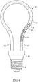
- an LED lamp with a heat dissipation effect comprises an LED device 10, a fixing block 20, a circuit board 30, and a lamp base 40.
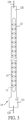
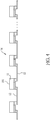
- the LED device 10 comprises a light bar 14 and a protective cover 16. As shown in FIG. 3 and FIG. 4 , the light bar 14 has multiple light emitting diode chips 11 (LED chips), multiple conductive substrates 12 and a packaging layer 13. Each LED chip 11 may be a double-sided light-emitting LED with a flip chip structure, or may have at least one top light-emitting surface 111. Each LED chip 11 can emit light from the top light-emitting surface 111 outwardly, wherein the top light-emitting surface 111 is at the top of the LED chip 11. Each of the conductive substrates 12 is a metal conductive sheet. The conductive substrates 12 are arranged in a sequence with an interval between each two adjacent conductive substrates 12.
- the packaging layer 13 includes at least one upper packaging layer 131 for covering one surface of the conductive substrates 12 and the LED chip 11 on the surface to form the light bar 14.
- the light bar 14 has flexibility.
- a first conductive portion 121 is formed on and extends from the conductive substrate 12 at one end of the light bar 14
- a second conductive portion 122 is formed on and extends from the conductive substrate 12 at the other end of the light bar 14, wherein the first conductive portion 121 and the second conductive portion 122 are two opposite electrodes.
- the first conductive portion 121 and the second conductive portion 122 can be each connected to a respective wire 123, 124 for receiving power.
- the light bar 14 of the present invention is not limited to be provided with two wires 123, 124. In other embodiments, the light bar 14 can be provided with a single wire as long as a power circuit can be formed.
- the conductive substrate 12 of the present invention is different from a conventional flexible PCB in that the width of the conductive substrate 12 is relatively narrow and can be between 2mm and 6mm, so as to reduce the effect of double-sided light emission when the width of the substrate is too large. In contrast, as the conductive substrate 12 of the present invention is narrow, a slim and comprehensive glow visual effect can be achieved when the LED chip 11 is lit.
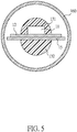
- the packaging layer 13 includes an upper packaging layer 131 and a lower packaging layer 132.
- a light-transmitting plate 15 is disposed on the lower surface of each conductive substrate 12 so that the light can be transmitted downward through the light-transmitting plate 15.
- the area of the light-transmitting plate 15 is greater than or equal to the area of each conductive substrate 12.
- the upper packaging layer 131 having a substantially semi-elliptical cross section, is disposed on the upper surface of the conductive substrate 12 and completely covers the plurality of LED chips 11.
- the lower packaging layer 132 having a substantially semi-elliptical cross section, covers the lower surfaces of the conductive substrate 12 and the LED chips 11.
- the protective cover 16 is a light-transmitting tube 160, and the light-transmitting tube 160 can be formed into different shapes.
- the light-transmitting tube 160 is a light-transmitting insulator for protecting the light bar 14 and allowing light to be transmitted.
- the light-transmitting tube 160 can be manufactured by extrusion molding, heating to soften the tube, and then putting the tube into a mold. Therefore, the light-transmitting tube 160 is made of a non-glass plastic material.
- the protective cover 16 is filled with cooling liquid 50.
- the cooling liquid 50 is light-transmitting, insulating and non-self-igniting, and may be silicon oil, for example. In one embodiment, a pigment or reflective particles can be added or dispensed in the cooling liquid to change color of the cooling liquid or enhance visual effect.
- sealing elements 161 are disposed into openings of two ends of the protective cover 16.
- the sealing elements 161 may be an annular block or a hollow sleeve. A through hole may be formed on each sealing element 161.
- the wires 123,124 at both ends of the light bar 14 can be connected to the circuit board 30 through the through holes of the sealing elements 161.
- the sealing elements 161 are the adhesive, and after the wires pass through the adhesive and the adhesive is hardened, the sealing elements 161 seal both ends of the protective cover 16.
- multiple holes 22 are formed in the fixing block 20.
- the fixing block 20 has two holes 22.
- Each hole 22 has a diameter matching an outer diameter of the protection cover 16.
- the first conductive portion 121 and the second conductive portion 122 at both ends of the LED device 10 are respectively inserted into the two holes 22 and fixed in the holes 22 to keep the LED device 10 fixed in position.
- the circuit board 30 is disposed inside the fixing block 20 and is provided with a plurality of electrode terminals.
- two electrode terminals 311a, 311b are formed on the circuit board 30 and have opposite polarities, for example, a positive electrode terminal and a negative electrode terminal.
- the positive electrode terminal is electrically connected to the first conductive portion 121, while the negative electrode terminal is electrically connected to the second conductive portion 122.
- a control circuit is formed on the circuit board 30 by electronic components, such as capacitors, resistors IC and so on.
- the lamp base 40 has a first electrical connection portion 41 therein and a second electrical connection portion 43 at a side thereof.
- the first electrical connection portion 41 and the second electrical connection portion 43 are for connecting to opposite polarities of an external power source.
- the first electrical connection portion 41 and the second electrical connection portion 43 are respectively electrically connected to the electrode connection points 311a, 311b of the circuit board 30.
- the second electrical connection portion 43 is a threaded structure.
- the cooling liquid 50 is injected into the protective cover 16 and directly contacts the light bar 14, so the heat energy generated by the LED chip 11 can be transferred to the cooling liquid 50, and then to the protective cover 16, and finally directly dissipated in the air, thereby achieving a good heat dissipation.
- the invention does not need extra metal cooling elements, so the lamp weight can be reduced.
- the strip-shaped protective cover 16 can be bent in various ways and is relatively elongated. If there is a significant temperature difference between different sections of the protective cover 16, the heat convection may occur in the cooling liquid 50 inside the protective cover 16. The cooling liquid 50 in the higher temperature section may flow to the lower temperature section. Then the heat dissipation efficiency can be improved by the heat convection.
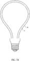
- the LED device 10 shown in FIG. 7A is bent into a circular shape, like a normal bulb.
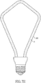
- FIG. 7B the LED device 10 is bent into a pear shape.
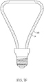
- FIG. 7C the LED device 10 is bent into a heart shape.
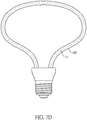
- FIG. 7D the LED device 10 is bent into an oval.
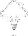
- the LED device 10 is bent into a triangle.
- the LED device 10 is bent into a trapezoid.
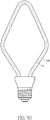
- the LED device 10 is bent into a diamond shape.
- the LED device 10 is bent into a sword shape.
- two LED devices 10 are bent and arranged in the shape of a Tai Chi symbol, and each LED device 10 is singly connected to the circuit board 30.
- the LED device 10 is bent into several different shapes to provide the user with a variety of modeling options.
- the protective cover 16 includes a light-transmitting tube 160 and at least one heat-dissipating tube 162.
- Two heat-dissipating tubes 162 are used as an example herein.
- the light bar 14 is covered by the light-transmitting tube 160.
- the material of the heat-dissipating tube 162 may be made of thermally conductive materials, such as metal.
- the heat-dissipating tubes 162 are also hollow and are respectively connected to two ends of the light-transmitting tube 160.
- the cooling liquid 50 can flow and transmit heat between the light-transmitting tube 160 and the heat-dissipating tubes 162.
- the cooling liquid 50 can directly contact the heat-dissipating tube 162 and the heat-dissipating tube 162 has a higher heat-dissipating efficiency than the light-transmitting tube 160 because of its material, the cooling liquid 50 can further improve the heat dissipation of the lamp.
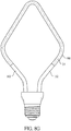
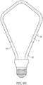
- multiple sections of linear bright and dark areas can be obtained by changing the position of the heat-dissipating tube 162, as shown in FIGS. 8A ⁇ 8H , which create specific visual effects.
- the LED device 10 in FIG. 8A is presented in a crescent shape.
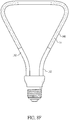
- the LED device 10 is in a half-pear shape as shown in FIG. 8B .
- the LED device 10 is in a semi-heart shape in FIG. 8C .
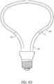
- the LED device 10 has a semi-elliptical shape in FIG. 8D .
- the LED device 10 is in a semi-triangular shape in FIG. 8E .
- the LED device 10 is in a semi-trapezoidal shape in FIG. 8F .
- the LED device 10 is in a semi-rhombus shape in FIG. 8G .
- the LED device 10 is in a semi-sword shape in FIG. 8H .
Landscapes
- Engineering & Computer Science (AREA)
- General Engineering & Computer Science (AREA)
- Physics & Mathematics (AREA)
- Microelectronics & Electronic Packaging (AREA)
- Optics & Photonics (AREA)
- Non-Portable Lighting Devices Or Systems Thereof (AREA)
- Fastening Of Light Sources Or Lamp Holders (AREA)
- Led Device Packages (AREA)
- Arrangement Of Elements, Cooling, Sealing, Or The Like Of Lighting Devices (AREA)
Claims (9)
- Ampoule à diodes électroluminescentes (DEL) avec un effet de dissipation de chaleur, caractérisée en ce que l'ampoule à DEL comprend :une barre lumineuse (14) ayant une pluralité de substrats conducteurs (12) et une pluralité de puces à DEL (11) disposées sur les substrats conducteurs (12), dans laquelle chaque puce à DEL (11) est une puce retournée électroluminescente à double face qui est hébergée et connectée électriquement par deux substrats adjacents desdits substrats conducteurs (12), et une surface supérieure et une surface inférieure de chacune des puces à DEL (11) sont respectivement recouvertes avec une couche d'encapsulation (13), dans laquelle la barre lumineuse (14) a au moins un conducteur (123, 124) connecté aux substrats conducteurs (12) ;un couvercle de protection (16) comprenant un tube de transmission de lumière d'isolation (160), dans laquelle le tube de transmission de lumière (160) est un tube en plastique formé par moulage par extrusion et recouvre la barre lumineuse (14) ;du liquide de refroidissement (50), qui est translucide et isolant, dans laquelle le liquide de refroidissement (50) remplit le couvercle de protection (16) et contacte la barre lumineuse (14) ;des éléments d'étanchéité (161) disposés dans le couvercle de protection (16) pour empêcher le liquide de refroidissement (50) de s'échapper, dans laquelle chacun des au moins un conducteurs (123, 124) de la barre lumineuse (14) passe à travers un élément respectif desdits éléments d'étanchéité (161) ;un bloc de fixation (20), dans laquelle une extrémité de la barre lumineuse (14) recouverte par le couvercle de protection (16) et remplie avec le liquide de refroidissement (50) est fixée au bloc de fixation (20), une carte de circuit (30) est disposée à l'intérieur du bloc de fixation (20), et la carte de circuit (30) est connectée électriquement à l'au moins un conducteur (123, 124) de la barre lumineuse (14) ; etun culot d'ampoule (40) monté sur le bloc de fixation (20) et connecté électriquement à la carte de circuit (30), dans laquelle le culot d'ampoule (40) est adapté pour la connexion à une source d'alimentation externe.
- Ampoule à DEL telle que revendiquée par la revendication 1, dans laquelle les éléments d'étanchéité (161) sont respectivement fournis à deux extrémités du tube de transmission de lumière (160).
- Ampoule à DEL telle que revendiquée par la revendication 1 ou 2, dans laquelle le couvercle de protection (16) comprend en outre au moins un tube de dissipation de chaleur (162), l'au moins un tube de dissipation de chaleur (162) est creux, est connecté au tube de transmission de lumière (160) et communique avec celui-ci, et le liquide de refroidissement (50) circule dans l'au moins un tube de dissipation de chaleur (162) et le tube de transmission de lumière (160) .
- Ampoule à DEL telle que revendiquée par la revendication 3, dans laquelle chacun des au moins un tubes de dissipation de chaleur (162) est un tube métallique.
- Ampoule à DEL telle que revendiquée par la revendication 4, dans laquelle l'au moins un tube de dissipation de chaleur (162) comprend deux tubes de dissipation de chaleur (162) respectivement connectés aux deux extrémités du tube de transmission de lumière (160), et les éléments d'étanchéité (161) sont fournis à une extrémité de chaque tube de dissipation de chaleur (162).
- Ampoule à DEL telle que revendiquée par la revendication 5, dans laquelle chacun des éléments d'étanchéité (161) est un bloc annulaire, un manchon creux, ou un adhésif durci.
- Ampoule à DEL telle que revendiquée par la revendication 1 ou 5, dans laquelle la barre lumineuse (14) recouverte par le couvercle de protection (16) a une forme d'un cercle, d'une poire, d'un coeur, d'un ovale, d'un triangle, d'un trapèze, d'un diamant, d'une épée ou d'un symbole de Tai Chi.
- Ampoule à DEL telle que revendiquée par la revendication 1, dans laquelle un pigment est ajouté dans le liquide de refroidissement (50).
- Ampoule à DEL telle que revendiquée par la revendication 1, dans laquelle des particules réfléchissantes sont ajoutées dans le liquide de refroidissement (50).
Applications Claiming Priority (1)
| Application Number | Priority Date | Filing Date | Title |
|---|---|---|---|
| US201762479327P | 2017-03-31 | 2017-03-31 |
Publications (2)
| Publication Number | Publication Date |
|---|---|
| EP3343098A1 EP3343098A1 (fr) | 2018-07-04 |
| EP3343098B1 true EP3343098B1 (fr) | 2019-06-05 |
Family
ID=61912961
Family Applications (1)
| Application Number | Title | Priority Date | Filing Date |
|---|---|---|---|
| EP18164133.3A Active EP3343098B1 (fr) | 2017-03-31 | 2018-03-27 | Lampe à diodes électroluminescentes à effet de dissipation de chaleur |
Country Status (7)
| Country | Link |
|---|---|
| US (2) | US10598314B2 (fr) |
| EP (1) | EP3343098B1 (fr) |
| JP (2) | JP6630381B2 (fr) |
| CN (3) | CN108662446B (fr) |
| DK (2) | DK3301354T3 (fr) |
| ES (2) | ES2784922T3 (fr) |
| TW (4) | TWI678495B (fr) |
Families Citing this family (10)
| Publication number | Priority date | Publication date | Assignee | Title |
|---|---|---|---|---|
| TWI678495B (zh) * | 2017-03-31 | 2019-12-01 | 液光固態照明股份有限公司 | 發光二極體燈具 |
| WO2020151994A1 (fr) * | 2019-01-24 | 2020-07-30 | Signify Holding B.V. | Agencement de filament à del |
| CN112113154B (zh) * | 2019-08-30 | 2025-12-19 | 蔡雄创 | 一种具有导电导热散热作用的基板 |
| TWI695951B (zh) * | 2019-11-07 | 2020-06-11 | 光寶科技股份有限公司 | 散熱式燈具結構 |
| CN111735034A (zh) * | 2020-06-22 | 2020-10-02 | 杨文玮 | 一种带散热结构的led电路板 |
| US11667433B2 (en) * | 2021-10-15 | 2023-06-06 | Hoch Brands, LLC | Three dimensional article |
| TWI778860B (zh) * | 2021-11-11 | 2022-09-21 | 液光固態照明股份有限公司 | 發光二極體燈泡 |
| USD1089724S1 (en) * | 2022-10-28 | 2025-08-19 | Cartier International Ag | Light bulb filament |
| CN115978507B (zh) * | 2022-12-30 | 2024-04-26 | 深圳爱图仕创新科技股份有限公司 | 一种液冷照明装置 |
| CN116608433A (zh) * | 2023-01-19 | 2023-08-18 | 杭州杭科光电集团股份有限公司 | 灯管、灯具及灯体 |
Family Cites Families (67)
| Publication number | Priority date | Publication date | Assignee | Title |
|---|---|---|---|---|
| US2885538A (en) | 1956-05-21 | 1959-05-05 | Joseph E Mahon | Neon tubing support |
| US4122142A (en) * | 1977-08-05 | 1978-10-24 | Owens-Illinois, Inc. | Method for blow molding a reinforced plastic bottle |
| US6371637B1 (en) | 1999-02-26 | 2002-04-16 | Radiantz, Inc. | Compact, flexible, LED array |
| US6379021B1 (en) | 2000-02-22 | 2002-04-30 | Whiter Shieh | Spiral decorative light tree |
| CN2413390Y (zh) | 2000-02-24 | 2001-01-03 | 台湾光宝电子股份有限公司 | 发光二极体装置 |
| JP2002057371A (ja) | 2000-08-15 | 2002-02-22 | Hukuyo Denkyu Kk | 連鎖led光源構造 |
| JP3075689U (ja) * | 2000-08-17 | 2001-02-27 | 舶用電球株式会社 | Led電球 |
| US6583550B2 (en) | 2000-10-24 | 2003-06-24 | Toyoda Gosei Co., Ltd. | Fluorescent tube with light emitting diodes |
| CN100547282C (zh) | 2002-04-25 | 2009-10-07 | 林原 | 可挠性发光体装置及其制造方法 |
| WO2004031648A2 (fr) | 2002-10-01 | 2004-04-15 | Sloanled, Inc. | Éclairage périmétrique incurvé et procédé de fabrication associé |
| US7490957B2 (en) | 2002-11-19 | 2009-02-17 | Denovo Lighting, L.L.C. | Power controls with photosensor for tube mounted LEDs with ballast |
| CN2611741Y (zh) | 2003-03-11 | 2004-04-14 | 伟力电器股份有限公司 | 展缩式树灯 |
| KR20050031792A (ko) | 2003-09-30 | 2005-04-06 | 삼성전자주식회사 | 용량가변 회전압축기 |
| CN2718387Y (zh) | 2004-03-17 | 2005-08-17 | 杨华贵 | 嵌设于塑胶体内的彩灯 |
| JP2007165811A (ja) * | 2005-12-16 | 2007-06-28 | Nichia Chem Ind Ltd | 発光装置 |
| US7922359B2 (en) * | 2006-07-17 | 2011-04-12 | Liquidleds Lighting Corp. | Liquid-filled LED lamp with heat dissipation means |
| US7635201B2 (en) | 2006-08-28 | 2009-12-22 | Deng Jia H | Lamp bar having multiple LED light sources |
| US8567992B2 (en) | 2006-09-12 | 2013-10-29 | Huizhou Light Engine Ltd. | Integrally formed light emitting diode light wire and uses thereof |
| US20090140271A1 (en) | 2007-11-30 | 2009-06-04 | Wen-Jyh Sah | Light emitting unit |
| TWI369142B (en) | 2008-01-22 | 2012-07-21 | Asustek Comp Inc | Audio system and a method for detecting and adjusting a sound field thereof |
| US9885449B2 (en) * | 2014-09-28 | 2018-02-06 | Jiaxing Super Lighting Electric Appliance Co., Ltd | LED tube lamp |
| US8382322B2 (en) * | 2008-12-08 | 2013-02-26 | Avx Corporation | Two part surface mount LED strip connector and LED assembly |
| CN101655189A (zh) * | 2009-07-16 | 2010-02-24 | 艾迪光电(杭州)有限公司 | 中空式液冷led条形灯 |
| TWM376709U (en) * | 2009-09-02 | 2010-03-21 | Liquidleds Lighting Corp | Curved tubular LED lamp |
| CN201568794U (zh) * | 2009-09-17 | 2010-09-01 | 液光固态照明股份有限公司 | 发光二极管弯管状灯泡 |
| JP5189211B2 (ja) * | 2010-07-20 | 2013-04-24 | パナソニック株式会社 | 電球形ランプ |
| CN201909220U (zh) | 2010-07-23 | 2011-07-27 | 展晶科技(深圳)有限公司 | 发光二极管灯条 |
| JP2012146559A (ja) * | 2011-01-13 | 2012-08-02 | Panasonic Corp | 照明器具 |
| TWM406136U (en) * | 2011-01-31 | 2011-06-21 | Liquidleds Lighting Corp | Standing-pipe-type LED bulb |
| US8314566B2 (en) * | 2011-02-22 | 2012-11-20 | Quarkstar Llc | Solid state lamp using light emitting strips |
| US8226274B2 (en) | 2011-03-01 | 2012-07-24 | Switch Bulb Company, Inc. | Liquid displacer in LED bulbs |
| JP5726339B2 (ja) | 2011-03-17 | 2015-05-27 | 北京優格莱照明科技有限公司 | 液冷式led照明灯 |
| JP5988792B2 (ja) * | 2011-09-29 | 2016-09-07 | キヤノン株式会社 | シート処理装置及び画像形成装置 |
| DE202011107736U1 (de) * | 2011-11-10 | 2011-12-01 | Holger Schumacher | LED-Einbauleuchte für abgehängte Decken |
| KR20130084884A (ko) * | 2012-01-18 | 2013-07-26 | 삼성전자주식회사 | 조명 장치 |
| JP3175965U (ja) * | 2012-03-21 | 2012-06-07 | サイバーコイン株式会社 | 直管蛍光灯型ledランプ |
| CN102644879B (zh) * | 2012-03-30 | 2015-09-09 | 深圳市华星光电技术有限公司 | 发光二极管灯条构造 |
| JP2014010889A (ja) * | 2012-06-27 | 2014-01-20 | Yamato Kogyo Kk | 照明装置の製造方法及び照明装置 |
| JP5970278B2 (ja) * | 2012-07-20 | 2016-08-17 | アイリスオーヤマ株式会社 | 直管形ledランプ |
| US20140048824A1 (en) * | 2012-08-15 | 2014-02-20 | Epistar Corporation | Light-emitting device |
| TW201430274A (zh) * | 2013-01-24 | 2014-08-01 | Chi Long Machinery Co Ltd | 全亮型燈條及其製造方法 |
| JP6210830B2 (ja) * | 2013-05-27 | 2017-10-11 | シチズン時計株式会社 | Led電球 |
| TWI599745B (zh) * | 2013-09-11 | 2017-09-21 | 晶元光電股份有限公司 | 可撓式發光二極體組件及發光二極體燈泡 |
| US9772076B2 (en) | 2013-09-30 | 2017-09-26 | Osram Sylvania Inc. | Cuttable flexible light engines |
| JP6282079B2 (ja) | 2013-10-22 | 2018-02-21 | 公益財団法人日本自動車輸送技術協会 | 排ガス採取装置及び排ガス分析システム |
| CN203517451U (zh) * | 2013-11-08 | 2014-04-02 | 江苏华英光宝科技股份有限公司 | 全角度可弯折led灯丝条及其构成的仿古led灯泡 |
| US10066791B2 (en) | 2013-12-02 | 2018-09-04 | Tiehan Ge | Spiral LED filament and light bulb using spiral LED filament |
| WO2015135817A1 (fr) * | 2014-03-13 | 2015-09-17 | Koninklijke Philips N.V. | Filament pour dispositif d'éclairage |
| JP2015179648A (ja) | 2014-03-20 | 2015-10-08 | 東芝ライテック株式会社 | 発光装置および照明装置 |
| CN104157772A (zh) | 2014-08-27 | 2014-11-19 | 江苏华英光宝科技股份有限公司 | 含正装芯片倒装360度发光可任意环绕led灯丝的led光源 |
| US9618166B2 (en) * | 2014-09-28 | 2017-04-11 | Jiaxing Super Lighting Electric Applianc Co., Ltd. | LED tube lamp |
| TWM502782U (zh) * | 2014-12-08 | 2015-06-11 | Dynacard Co Ltd | 微型燈管結構 |
| CN105161608B (zh) * | 2015-07-03 | 2017-12-19 | 山东浪潮华光光电子股份有限公司 | 一种led灯丝发光条及其制备方法 |
| CN205137089U (zh) * | 2015-09-23 | 2016-04-06 | 厦门多彩光电子科技有限公司 | 一种可随意变换发光方向的led灯丝及灯丝灯 |
| CN205065326U (zh) * | 2015-10-16 | 2016-03-02 | 浙江阳光美加照明有限公司 | 一种柔性基板led充气灯 |
| CN105889814A (zh) * | 2015-11-13 | 2016-08-24 | 乐视致新电子科技(天津)有限公司 | 一种led灯组、背光模组及显示设备 |
| CN205299146U (zh) * | 2015-12-24 | 2016-06-08 | 东莞中之光电股份有限公司 | 一种双端收口led玻璃灯管 |
| TWM523810U (zh) * | 2016-02-26 | 2016-06-11 | Liquidleds Lighting Corp | 發光二極體光源及燈具 |
| TW201621210A (zh) | 2016-02-26 | 2016-06-16 | 液光固態照明股份有限公司 | 發光二極體光源及燈具 |
| CN105570701B (zh) | 2016-02-29 | 2018-10-30 | 中国计量科学研究院 | 一种led灯丝发光强度标准灯 |
| CN205640356U (zh) * | 2016-04-29 | 2016-10-12 | 福建明业新能源科技有限公司 | 新型led灯的发光管构造 |
| CN205746182U (zh) * | 2016-05-30 | 2016-11-30 | 开发晶照明(厦门)有限公司 | Led灯管以及机台设备 |
| CN106090644A (zh) * | 2016-06-29 | 2016-11-09 | 天津贝力移动照明设备制造有限公司 | Led 照明灯 |
| CN205806997U (zh) * | 2016-07-20 | 2016-12-14 | 山东晶泰星光电科技有限公司 | 一种led充气球泡灯 |
| TW201705557A (zh) | 2016-10-26 | 2017-02-01 | 液光固態照明股份有限公司 | 具有散熱結構的led燈絲及應用該led燈絲的led燈泡 |
| CN207364684U (zh) * | 2017-03-31 | 2018-05-15 | 液光固态照明股份有限公司 | 发光二极体灯具 |
| TWI678495B (zh) * | 2017-03-31 | 2019-12-01 | 液光固態照明股份有限公司 | 發光二極體燈具 |
-
2017
- 2017-10-23 TW TW106136278A patent/TWI678495B/zh active
- 2017-10-23 TW TW106215561U patent/TWM559977U/zh unknown
- 2017-11-09 CN CN201711099503.9A patent/CN108662446B/zh active Active
- 2017-12-20 US US15/848,003 patent/US10598314B2/en active Active
-
2018
- 2018-01-09 DK DK18150711.2T patent/DK3301354T3/da active
- 2018-01-09 ES ES18150711T patent/ES2784922T3/es active Active
- 2018-02-02 JP JP2018017323A patent/JP6630381B2/ja active Active
- 2018-02-14 TW TW107202433U patent/TWM563517U/zh unknown
- 2018-02-14 TW TW107105600A patent/TWI638118B/zh active
- 2018-03-09 CN CN201820322059.6U patent/CN208312001U/zh not_active Expired - Fee Related
- 2018-03-09 CN CN201810192991.6A patent/CN108692200B/zh active Active
- 2018-03-26 US US15/935,547 patent/US10619798B2/en active Active
- 2018-03-27 ES ES18164133T patent/ES2734873T3/es active Active
- 2018-03-27 EP EP18164133.3A patent/EP3343098B1/fr active Active
- 2018-03-27 DK DK18164133.3T patent/DK3343098T3/da active
- 2018-03-28 JP JP2018061657A patent/JP6517974B2/ja active Active
Non-Patent Citations (1)
| Title |
|---|
| None * |
Also Published As
| Publication number | Publication date |
|---|---|
| DK3343098T3 (da) | 2019-08-19 |
| CN108692200B (zh) | 2020-06-02 |
| US20180283619A1 (en) | 2018-10-04 |
| CN108662446A (zh) | 2018-10-16 |
| US10619798B2 (en) | 2020-04-14 |
| JP6517974B2 (ja) | 2019-05-22 |
| CN108662446B (zh) | 2020-06-23 |
| TW201837374A (zh) | 2018-10-16 |
| TWI638118B (zh) | 2018-10-11 |
| TWI678495B (zh) | 2019-12-01 |
| ES2734873T3 (es) | 2019-12-12 |
| EP3343098A1 (fr) | 2018-07-04 |
| CN108692200A (zh) | 2018-10-23 |
| JP2018174135A (ja) | 2018-11-08 |
| TW201812205A (zh) | 2018-04-01 |
| ES2784922T3 (es) | 2020-10-02 |
| JP2018174126A (ja) | 2018-11-08 |
| US10598314B2 (en) | 2020-03-24 |
| DK3301354T3 (da) | 2020-05-11 |
| JP6630381B2 (ja) | 2020-01-15 |
| US20180283674A1 (en) | 2018-10-04 |
| CN208312001U (zh) | 2019-01-01 |
| TWM563517U (zh) | 2018-07-11 |
| TWM559977U (zh) | 2018-05-11 |
Similar Documents
| Publication | Publication Date | Title |
|---|---|---|
| US10619798B2 (en) | LED lamp with heat dissipation effect | |
| US8596820B2 (en) | LED unit and LED lighting lamp using the LED unit | |
| CN105280796A (zh) | 发光装置 | |
| US20110001417A1 (en) | LED bulb with heat removal device | |
| KR101080700B1 (ko) | 조명 장치 | |
| EP2077415B1 (fr) | Ampoule DEL avec dispositif d'évacuation de la chaleur | |
| WO2017124784A1 (fr) | Lampe à incandescence à del électroluminescente à grand angle | |
| EP2184790A1 (fr) | Diode électroluminescente et module source de lumière la comprenant | |
| EP2753873B1 (fr) | Dispositif d'éclairage | |
| EP3104067B1 (fr) | Appareil d'éclairage | |
| JP2012022855A (ja) | 照明装置 | |
| JP2011129323A (ja) | 蛍光灯型ledランプ | |
| US8517569B2 (en) | Illumination device | |
| CN207364684U (zh) | 发光二极体灯具 | |
| KR101063925B1 (ko) | 조명 장치 | |
| US20160003419A1 (en) | Lighting device and led luminaire | |
| CN205372147U (zh) | 大角度发光led灯丝灯 | |
| KR101080699B1 (ko) | 광원 모듈 및 이를 포함하는 조명 장치 | |
| KR102089625B1 (ko) | 조명 장치 | |
| KR20130065915A (ko) | 조명 장치 | |
| KR102075125B1 (ko) | 조명기기 | |
| KR101977649B1 (ko) | 조명 장치 | |
| KR101103523B1 (ko) | 조명 장치 | |
| KR20140063922A (ko) | Led 조명장치 | |
| CN107781668A (zh) | Led灯丝灯 |
Legal Events
| Date | Code | Title | Description |
|---|---|---|---|
| PUAI | Public reference made under article 153(3) epc to a published international application that has entered the european phase |
Free format text: ORIGINAL CODE: 0009012 |
|
| STAA | Information on the status of an ep patent application or granted ep patent |
Free format text: STATUS: THE APPLICATION HAS BEEN PUBLISHED |
|
| AK | Designated contracting states |
Kind code of ref document: A1 Designated state(s): AL AT BE BG CH CY CZ DE DK EE ES FI FR GB GR HR HU IE IS IT LI LT LU LV MC MK MT NL NO PL PT RO RS SE SI SK SM TR |
|
| AX | Request for extension of the european patent |
Extension state: BA ME |
|
| STAA | Information on the status of an ep patent application or granted ep patent |
Free format text: STATUS: REQUEST FOR EXAMINATION WAS MADE |
|
| 17P | Request for examination filed |
Effective date: 20180820 |
|
| RBV | Designated contracting states (corrected) |
Designated state(s): AL AT BE BG CH CY CZ DE DK EE ES FI FR GB GR HR HU IE IS IT LI LT LU LV MC MK MT NL NO PL PT RO RS SE SI SK SM TR |
|
| GRAP | Despatch of communication of intention to grant a patent |
Free format text: ORIGINAL CODE: EPIDOSNIGR1 |
|
| STAA | Information on the status of an ep patent application or granted ep patent |
Free format text: STATUS: GRANT OF PATENT IS INTENDED |
|
| INTG | Intention to grant announced |
Effective date: 20181220 |
|
| GRAS | Grant fee paid |
Free format text: ORIGINAL CODE: EPIDOSNIGR3 |
|
| GRAA | (expected) grant |
Free format text: ORIGINAL CODE: 0009210 |
|
| STAA | Information on the status of an ep patent application or granted ep patent |
Free format text: STATUS: THE PATENT HAS BEEN GRANTED |
|
| AK | Designated contracting states |
Kind code of ref document: B1 Designated state(s): AL AT BE BG CH CY CZ DE DK EE ES FI FR GB GR HR HU IE IS IT LI LT LU LV MC MK MT NL NO PL PT RO RS SE SI SK SM TR |
|
| REG | Reference to a national code |
Ref country code: GB Ref legal event code: FG4D |
|
| REG | Reference to a national code |
Ref country code: CH Ref legal event code: EP |
|
| REG | Reference to a national code |
Ref country code: AT Ref legal event code: REF Ref document number: 1140370 Country of ref document: AT Kind code of ref document: T Effective date: 20190615 |
|
| REG | Reference to a national code |
Ref country code: IE Ref legal event code: FG4D |
|
| REG | Reference to a national code |
Ref country code: DE Ref legal event code: R096 Ref document number: 602018000116 Country of ref document: DE |
|
| REG | Reference to a national code |
Ref country code: SE Ref legal event code: TRGR |
|
| REG | Reference to a national code |
Ref country code: DK Ref legal event code: T3 Effective date: 20190816 |
|
| REG | Reference to a national code |
Ref country code: NL Ref legal event code: FP |
|
| REG | Reference to a national code |
Ref country code: LT Ref legal event code: MG4D |
|
| PG25 | Lapsed in a contracting state [announced via postgrant information from national office to epo] |
Ref country code: FI Free format text: LAPSE BECAUSE OF FAILURE TO SUBMIT A TRANSLATION OF THE DESCRIPTION OR TO PAY THE FEE WITHIN THE PRESCRIBED TIME-LIMIT Effective date: 20190605 Ref country code: HR Free format text: LAPSE BECAUSE OF FAILURE TO SUBMIT A TRANSLATION OF THE DESCRIPTION OR TO PAY THE FEE WITHIN THE PRESCRIBED TIME-LIMIT Effective date: 20190605 Ref country code: LT Free format text: LAPSE BECAUSE OF FAILURE TO SUBMIT A TRANSLATION OF THE DESCRIPTION OR TO PAY THE FEE WITHIN THE PRESCRIBED TIME-LIMIT Effective date: 20190605 Ref country code: AL Free format text: LAPSE BECAUSE OF FAILURE TO SUBMIT A TRANSLATION OF THE DESCRIPTION OR TO PAY THE FEE WITHIN THE PRESCRIBED TIME-LIMIT Effective date: 20190605 Ref country code: NO Free format text: LAPSE BECAUSE OF FAILURE TO SUBMIT A TRANSLATION OF THE DESCRIPTION OR TO PAY THE FEE WITHIN THE PRESCRIBED TIME-LIMIT Effective date: 20190905 |
|
| PG25 | Lapsed in a contracting state [announced via postgrant information from national office to epo] |
Ref country code: GR Free format text: LAPSE BECAUSE OF FAILURE TO SUBMIT A TRANSLATION OF THE DESCRIPTION OR TO PAY THE FEE WITHIN THE PRESCRIBED TIME-LIMIT Effective date: 20190906 Ref country code: LV Free format text: LAPSE BECAUSE OF FAILURE TO SUBMIT A TRANSLATION OF THE DESCRIPTION OR TO PAY THE FEE WITHIN THE PRESCRIBED TIME-LIMIT Effective date: 20190605 Ref country code: BG Free format text: LAPSE BECAUSE OF FAILURE TO SUBMIT A TRANSLATION OF THE DESCRIPTION OR TO PAY THE FEE WITHIN THE PRESCRIBED TIME-LIMIT Effective date: 20190905 Ref country code: RS Free format text: LAPSE BECAUSE OF FAILURE TO SUBMIT A TRANSLATION OF THE DESCRIPTION OR TO PAY THE FEE WITHIN THE PRESCRIBED TIME-LIMIT Effective date: 20190605 |
|
| REG | Reference to a national code |
Ref country code: ES Ref legal event code: FG2A Ref document number: 2734873 Country of ref document: ES Kind code of ref document: T3 Effective date: 20191212 |
|
| REG | Reference to a national code |
Ref country code: AT Ref legal event code: MK05 Ref document number: 1140370 Country of ref document: AT Kind code of ref document: T Effective date: 20190605 |
|
| PG25 | Lapsed in a contracting state [announced via postgrant information from national office to epo] |
Ref country code: SK Free format text: LAPSE BECAUSE OF FAILURE TO SUBMIT A TRANSLATION OF THE DESCRIPTION OR TO PAY THE FEE WITHIN THE PRESCRIBED TIME-LIMIT Effective date: 20190605 Ref country code: RO Free format text: LAPSE BECAUSE OF FAILURE TO SUBMIT A TRANSLATION OF THE DESCRIPTION OR TO PAY THE FEE WITHIN THE PRESCRIBED TIME-LIMIT Effective date: 20190605 Ref country code: CZ Free format text: LAPSE BECAUSE OF FAILURE TO SUBMIT A TRANSLATION OF THE DESCRIPTION OR TO PAY THE FEE WITHIN THE PRESCRIBED TIME-LIMIT Effective date: 20190605 Ref country code: PT Free format text: LAPSE BECAUSE OF FAILURE TO SUBMIT A TRANSLATION OF THE DESCRIPTION OR TO PAY THE FEE WITHIN THE PRESCRIBED TIME-LIMIT Effective date: 20191007 Ref country code: AT Free format text: LAPSE BECAUSE OF FAILURE TO SUBMIT A TRANSLATION OF THE DESCRIPTION OR TO PAY THE FEE WITHIN THE PRESCRIBED TIME-LIMIT Effective date: 20190605 Ref country code: EE Free format text: LAPSE BECAUSE OF FAILURE TO SUBMIT A TRANSLATION OF THE DESCRIPTION OR TO PAY THE FEE WITHIN THE PRESCRIBED TIME-LIMIT Effective date: 20190605 |
|
| PG25 | Lapsed in a contracting state [announced via postgrant information from national office to epo] |
Ref country code: IS Free format text: LAPSE BECAUSE OF FAILURE TO SUBMIT A TRANSLATION OF THE DESCRIPTION OR TO PAY THE FEE WITHIN THE PRESCRIBED TIME-LIMIT Effective date: 20191005 Ref country code: SM Free format text: LAPSE BECAUSE OF FAILURE TO SUBMIT A TRANSLATION OF THE DESCRIPTION OR TO PAY THE FEE WITHIN THE PRESCRIBED TIME-LIMIT Effective date: 20190605 |
|
| REG | Reference to a national code |
Ref country code: DE Ref legal event code: R097 Ref document number: 602018000116 Country of ref document: DE |
|
| PG25 | Lapsed in a contracting state [announced via postgrant information from national office to epo] |
Ref country code: TR Free format text: LAPSE BECAUSE OF FAILURE TO SUBMIT A TRANSLATION OF THE DESCRIPTION OR TO PAY THE FEE WITHIN THE PRESCRIBED TIME-LIMIT Effective date: 20190605 |
|
| PLBE | No opposition filed within time limit |
Free format text: ORIGINAL CODE: 0009261 |
|
| STAA | Information on the status of an ep patent application or granted ep patent |
Free format text: STATUS: NO OPPOSITION FILED WITHIN TIME LIMIT |
|
| PG25 | Lapsed in a contracting state [announced via postgrant information from national office to epo] |
Ref country code: PL Free format text: LAPSE BECAUSE OF FAILURE TO SUBMIT A TRANSLATION OF THE DESCRIPTION OR TO PAY THE FEE WITHIN THE PRESCRIBED TIME-LIMIT Effective date: 20190605 |
|
| 26N | No opposition filed |
Effective date: 20200306 |
|
| PG25 | Lapsed in a contracting state [announced via postgrant information from national office to epo] |
Ref country code: MC Free format text: LAPSE BECAUSE OF FAILURE TO SUBMIT A TRANSLATION OF THE DESCRIPTION OR TO PAY THE FEE WITHIN THE PRESCRIBED TIME-LIMIT Effective date: 20190605 |
|
| PG25 | Lapsed in a contracting state [announced via postgrant information from national office to epo] |
Ref country code: LU Free format text: LAPSE BECAUSE OF NON-PAYMENT OF DUE FEES Effective date: 20200327 |
|
| PG25 | Lapsed in a contracting state [announced via postgrant information from national office to epo] |
Ref country code: IE Free format text: LAPSE BECAUSE OF NON-PAYMENT OF DUE FEES Effective date: 20200327 |
|
| PGFP | Annual fee paid to national office [announced via postgrant information from national office to epo] |
Ref country code: SE Payment date: 20210316 Year of fee payment: 4 Ref country code: DK Payment date: 20210323 Year of fee payment: 4 |
|
| PGFP | Annual fee paid to national office [announced via postgrant information from national office to epo] |
Ref country code: CH Payment date: 20210628 Year of fee payment: 4 |
|
| PGFP | Annual fee paid to national office [announced via postgrant information from national office to epo] |
Ref country code: ES Payment date: 20210709 Year of fee payment: 4 |
|
| PGFP | Annual fee paid to national office [announced via postgrant information from national office to epo] |
Ref country code: BE Payment date: 20211230 Year of fee payment: 5 |
|
| PGFP | Annual fee paid to national office [announced via postgrant information from national office to epo] |
Ref country code: GB Payment date: 20220105 Year of fee payment: 5 |
|
| PG25 | Lapsed in a contracting state [announced via postgrant information from national office to epo] |
Ref country code: MT Free format text: LAPSE BECAUSE OF FAILURE TO SUBMIT A TRANSLATION OF THE DESCRIPTION OR TO PAY THE FEE WITHIN THE PRESCRIBED TIME-LIMIT Effective date: 20190605 Ref country code: CY Free format text: LAPSE BECAUSE OF FAILURE TO SUBMIT A TRANSLATION OF THE DESCRIPTION OR TO PAY THE FEE WITHIN THE PRESCRIBED TIME-LIMIT Effective date: 20190605 |
|
| PGFP | Annual fee paid to national office [announced via postgrant information from national office to epo] |
Ref country code: IT Payment date: 20211230 Year of fee payment: 5 Ref country code: FR Payment date: 20220127 Year of fee payment: 5 |
|
| PG25 | Lapsed in a contracting state [announced via postgrant information from national office to epo] |
Ref country code: MK Free format text: LAPSE BECAUSE OF FAILURE TO SUBMIT A TRANSLATION OF THE DESCRIPTION OR TO PAY THE FEE WITHIN THE PRESCRIBED TIME-LIMIT Effective date: 20190605 |
|
| PGFP | Annual fee paid to national office [announced via postgrant information from national office to epo] |
Ref country code: NL Payment date: 20220326 Year of fee payment: 5 |
|
| REG | Reference to a national code |
Ref country code: DK Ref legal event code: EBP Effective date: 20220331 |
|
| REG | Reference to a national code |
Ref country code: CH Ref legal event code: PL |
|
| PG25 | Lapsed in a contracting state [announced via postgrant information from national office to epo] |
Ref country code: SE Free format text: LAPSE BECAUSE OF NON-PAYMENT OF DUE FEES Effective date: 20220328 Ref country code: LI Free format text: LAPSE BECAUSE OF NON-PAYMENT OF DUE FEES Effective date: 20220331 Ref country code: CH Free format text: LAPSE BECAUSE OF NON-PAYMENT OF DUE FEES Effective date: 20220331 |
|
| PG25 | Lapsed in a contracting state [announced via postgrant information from national office to epo] |
Ref country code: DK Free format text: LAPSE BECAUSE OF NON-PAYMENT OF DUE FEES Effective date: 20220331 |
|
| REG | Reference to a national code |
Ref country code: ES Ref legal event code: FD2A Effective date: 20230428 |
|
| PG25 | Lapsed in a contracting state [announced via postgrant information from national office to epo] |
Ref country code: ES Free format text: LAPSE BECAUSE OF NON-PAYMENT OF DUE FEES Effective date: 20220328 |
|
| PG25 | Lapsed in a contracting state [announced via postgrant information from national office to epo] |
Ref country code: SI Free format text: LAPSE BECAUSE OF FAILURE TO SUBMIT A TRANSLATION OF THE DESCRIPTION OR TO PAY THE FEE WITHIN THE PRESCRIBED TIME-LIMIT Effective date: 20190605 |
|
| REG | Reference to a national code |
Ref country code: NL Ref legal event code: MM Effective date: 20230401 |
|
| GBPC | Gb: european patent ceased through non-payment of renewal fee |
Effective date: 20230327 |
|
| REG | Reference to a national code |
Ref country code: BE Ref legal event code: MM Effective date: 20230331 |
|
| PG25 | Lapsed in a contracting state [announced via postgrant information from national office to epo] |
Ref country code: NL Free format text: LAPSE BECAUSE OF NON-PAYMENT OF DUE FEES Effective date: 20230401 |
|
| PG25 | Lapsed in a contracting state [announced via postgrant information from national office to epo] |
Ref country code: GB Free format text: LAPSE BECAUSE OF NON-PAYMENT OF DUE FEES Effective date: 20230327 |
|
| PG25 | Lapsed in a contracting state [announced via postgrant information from national office to epo] |
Ref country code: GB Free format text: LAPSE BECAUSE OF NON-PAYMENT OF DUE FEES Effective date: 20230327 Ref country code: FR Free format text: LAPSE BECAUSE OF NON-PAYMENT OF DUE FEES Effective date: 20230331 |
|
| PG25 | Lapsed in a contracting state [announced via postgrant information from national office to epo] |
Ref country code: BE Free format text: LAPSE BECAUSE OF NON-PAYMENT OF DUE FEES Effective date: 20230331 |
|
| PG25 | Lapsed in a contracting state [announced via postgrant information from national office to epo] |
Ref country code: IT Free format text: LAPSE BECAUSE OF NON-PAYMENT OF DUE FEES Effective date: 20230327 |
|
| PGFP | Annual fee paid to national office [announced via postgrant information from national office to epo] |
Ref country code: DE Payment date: 20250102 Year of fee payment: 8 |