EP3343109B1 - Dispositif de cuisson - Google Patents
Dispositif de cuisson Download PDFInfo
- Publication number
- EP3343109B1 EP3343109B1 EP16838807.2A EP16838807A EP3343109B1 EP 3343109 B1 EP3343109 B1 EP 3343109B1 EP 16838807 A EP16838807 A EP 16838807A EP 3343109 B1 EP3343109 B1 EP 3343109B1
- Authority
- EP
- European Patent Office
- Prior art keywords
- memory card
- cooking device
- heat cooking
- attaching mechanism
- card
- Prior art date
- Legal status (The legal status is an assumption and is not a legal conclusion. Google has not performed a legal analysis and makes no representation as to the accuracy of the status listed.)
- Active
Links
Images




Classifications
-
- H—ELECTRICITY
- H05—ELECTRIC TECHNIQUES NOT OTHERWISE PROVIDED FOR
- H05B—ELECTRIC HEATING; ELECTRIC LIGHT SOURCES NOT OTHERWISE PROVIDED FOR; CIRCUIT ARRANGEMENTS FOR ELECTRIC LIGHT SOURCES, IN GENERAL
- H05B6/00—Heating by electric, magnetic or electromagnetic fields
- H05B6/64—Heating using microwaves
- H05B6/6435—Aspects relating to the user interface of the microwave heating apparatus
- H05B6/6441—Aspects relating to the user interface of the microwave heating apparatus allowing the input of coded operation instructions, e.g. bar code reader
-
- F—MECHANICAL ENGINEERING; LIGHTING; HEATING; WEAPONS; BLASTING
- F24—HEATING; RANGES; VENTILATING
- F24C—DOMESTIC STOVES OR RANGES ; DETAILS OF DOMESTIC STOVES OR RANGES, OF GENERAL APPLICATION
- F24C7/00—Stoves or ranges heated by electric energy
- F24C7/08—Arrangement or mounting of control or safety devices
- F24C7/082—Arrangement or mounting of control or safety devices on ranges, e.g. control panels, illumination
- F24C7/085—Arrangement or mounting of control or safety devices on ranges, e.g. control panels, illumination on baking ovens
-
- H—ELECTRICITY
- H05—ELECTRIC TECHNIQUES NOT OTHERWISE PROVIDED FOR
- H05B—ELECTRIC HEATING; ELECTRIC LIGHT SOURCES NOT OTHERWISE PROVIDED FOR; CIRCUIT ARRANGEMENTS FOR ELECTRIC LIGHT SOURCES, IN GENERAL
- H05B6/00—Heating by electric, magnetic or electromagnetic fields
- H05B6/64—Heating using microwaves
- H05B6/6426—Aspects relating to the exterior of the microwave heating apparatus, e.g. metal casing, power cord
-
- H—ELECTRICITY
- H05—ELECTRIC TECHNIQUES NOT OTHERWISE PROVIDED FOR
- H05B—ELECTRIC HEATING; ELECTRIC LIGHT SOURCES NOT OTHERWISE PROVIDED FOR; CIRCUIT ARRANGEMENTS FOR ELECTRIC LIGHT SOURCES, IN GENERAL
- H05B6/00—Heating by electric, magnetic or electromagnetic fields
- H05B6/64—Heating using microwaves
- H05B6/6435—Aspects relating to the user interface of the microwave heating apparatus
-
- F—MECHANICAL ENGINEERING; LIGHTING; HEATING; WEAPONS; BLASTING
- F24—HEATING; RANGES; VENTILATING
- F24C—DOMESTIC STOVES OR RANGES ; DETAILS OF DOMESTIC STOVES OR RANGES, OF GENERAL APPLICATION
- F24C15/00—Details
- F24C15/006—Arrangements for circulation of cooling air
Definitions
- the present disclosure relates to heat cooking devices used to microwave-heat an object by radiating microwaves, and, in particular, relates to a commercial heat cooking device used as a cooking apparatus in commercial facilities including stores and restaurants such as convenience stores and fast-food restaurants.
- commercial heat cooking devices used in stores and restaurants such as convenience stores and fast-food restaurants are configured as described below.
- a microwave-heating mode with which an object is heat cooked by radiating microwaves a grill mode with which the object is heat cooked through radiation heating using a heater, and a convection mode with which the object is heat cooked by using a fan to circulate air heated by the heater in a convection manner in a heating chamber.
- the commercial heat cooking devices used in stores and restaurants are required to securely execute each heating process for heat cooking at a precise temperature and a precise time. Therefore, the commercial heat cooking devices are configured such that a processing condition for each heating process is set beforehand, and the set processing condition is stored in a storage medium. Therefore, in each of stores and restaurants, by using a commercial heat cooking device provided with a storage medium, heat cooking can precisely be performed under an identical processing condition for an identical menu when ordered by a customer.
- some commercial heat cooking devices are equipped with a storage medium storing heat cooking processing conditions so as to respond to various menus.
- a storage medium storing heat cooking processing conditions so as to respond to various menus.
- a processing condition for each heating process should be changed each time a menu is changed
- a replaceable memory card is used as the storage medium. Therefore, by changing a memory card, changing menus, for example, can easily be performed (e.g., see PTL 1).
- a commercial heat cooking device In order to promptly respond to an order of a customer, a commercial heat cooking device is always turned on, and accordingly a cooling fan operates and a heating chamber is preheated.
- a waterproof measure should be taken because a commercial heat cooking device is often installed around a sink in a kitchen of a store or a restaurant, for example, and is sometimes spilled with water during cooking or cleaning, for example.
- an attaching mechanism to be inserted with a memory card served as a storage medium requires a configuration where no dust and dirt enter, as well as requires an insulation structure so as not to be subject to a high temperature. Therefore, a conventional commercial heat cooking device requires a special member and a larger space for providing an attaching mechanism for inserting a memory card.
- An exterior plate for covering a card insertion port for inserting a memory card is also required if the card insertion port is provided on a front face side of a commercial heat cooking device.
- a label for indicating that the card insertion port is covered is required, as well as edges of the exterior plate should be smoothed such that a customer will not be suffered from an injury when the customer has touched the exterior plate.
- a commercial heat cooking device should be configured such that a user such as an employee of a store or a restaurant can replace a memory card, as well as a third party cannot easily access the memory card in order to prevent information from leaking, for example.
- the present disclosure has an object to achieve a commercial heat cooking device including a mechanism to be inserted with a memory card, which can neither easily be viewed externally, nor easily be accessed by a third party. Further, the mechanism to be inserted with the memory card has a configuration that does not allow dirt and dust to easily enter, that is not to be subject to a high temperature, and that does not require a special waterproof measure.
- a heat cooking device includes a main body having a heating chamber for accommodating and heating an object, a machine chamber provided under the main body and provided with a mechanism for forming and transmitting microwaves for microwave heating in the heating chamber, a front grille panel detachably provided on a front face of the machine chamber, a door openably configured with respect to the heating chamber, and a memory card attaching mechanism configured to insert a memory card into the main body.
- the memory card attaching mechanism is configured to have, on a lower face of the main body, a card insertion port for inserting the memory card vertically upward.
- the card insertion port is configured to be hidden by the front grille panel attached to the machine chamber so as not to be exposed from the heat cooking device.
- the present disclosure can provide a reliable commercial heat cooking device including a memory card attaching mechanism, which can neither easily be viewed externally, nor easily be accessed by a third party, without requiring a special waterproof measure.
- a heat cooking device includes a main body having a heating chamber for accommodating and heating an object, a machine chamber provided under the main body and provided with a mechanism for forming and transmitting microwaves for microwave heating in the heating chamber, a front grille panel detachably provided on a front face of the machine chamber, a door openably configured with respect to the heating chamber, and a memory card attaching mechanism configured to insert a memory card into the main body.
- the memory card attaching mechanism is configured to have, on a lower face of the main body, a card insertion port for inserting the memory card vertically upward.
- the card insertion port is configured to be hidden by the front grille panel attached to the machine chamber so as not to be exposed from the heat cooking device.
- the heat cooking device can provide a reliable commercial heat cooking device including a memory card attaching mechanism, which can neither easily be viewed externally, nor easily be accessed by a third party, without further requiring a special waterproof measure.
- a heat cooking device is configured such that the card insertion port of the memory card attaching mechanism according to the first aspect is provided on a lower face of an operation unit provided on a front face of the main body so that a memory card inserted into the memory card attaching mechanism is accommodated in the operation unit.
- the heat cooking device has a structure in which the operation unit itself is insulated from the heating chamber, and no heating component is present in the operation unit.
- inside of the operation unit is not included in a path into which a cooling fan blows air, for example, and thus foreign materials including dust and dirt would be less likely to enter. Therefore, in the configuration of the heat cooking device according to the second aspect of the present disclosure, no special insulation structure is required in the memory card attaching mechanism, and no special structure is required for preventing foreign materials including dust and dirt from entering.
- the wiring path can be significantly less likely to be affected by noise.
- a card cover for covering the card insertion port according to the second aspect from beneath is rotatably provided.
- the third aspect of the present disclosure can provide a reliable heat cooking device in which foreign materials including water and dust do not enter from the card insertion port of the memory card attaching mechanism.
- the operation unit according to the third aspect is internally configured such that a flat face of the memory card inserted into the memory card attaching mechanism is in parallel to a mounting face of the electric circuit board provided in the operation unit.
- the heat cooking device is advantageous because the configuration in the operation unit can be simplified, as well as a required space in the operation unit can be reduced.
- a heat cooking device is configured such that the cooling fan for cooling the mechanism in the machine chamber, according to the fourth aspect, blows outside air taken from the front grille panel via an outside air intake port formed on the front face of the machine chamber into the machine chamber.
- the memory card attaching mechanism is disposed away from a path into which the cooling fan blows the outside air.
- the fifth aspect of the present disclosure can provide a reliable heat cooking device in which the memory card attaching mechanism is disposed away from the path into which outside air is blown, i.e., is not present in the path into which air is blown, and therefore, foreign materials including dust and dirt would be significantly less likely to enter.
- a microwave oven served as a microwave heater capable of executing a microwave-heating mode, a grill mode, and a convection mode is used.
- the heat cooking device that is a commercial microwave oven used in stores and restaurants, in particular, used in convenience stores and fast-food restaurants will now be described herein with reference to the accompanied drawings.
- a configuration of the heat cooking device according to the present disclosure is not limited to a configuration of the commercial microwave oven described in the below exemplary embodiment, but includes a configuration of a heat cooking device based on a technical idea equivalent to a technical idea described in the below exemplary embodiment.
- FIG. 1 is a perspective view illustrating an appearance of heat cooking device 10 according to the exemplary embodiment of the present disclosure when its door formed on a front face of heat cooking device 10 is closed.
- FIG. 2 the door of heat cooking device 10 shown in FIG. 1 is open, and thus a heating chamber formed in heat cooking device 10 is open.
- Heat cooking device 10 is a commercial microwave oven used in stores and restaurants, in particular, used in convenience stores and fast-food restaurants, has a maximum output ranging from 1200 W to 1300 W, and is configured to be capable of switching an output in plural steps.
- heat cooking device 10 includes main body 1 configuring an outer case of the heating chamber, machine chamber 2 provided under main body 1 so as to support main body 1, and door 3 attached on a front face side of main body 1.
- Detachable front grille panel 12 is provided on a front face side of machine chamber 2.
- heating chamber 4 is formed inside of main body 1.
- Heating chamber 4 is a space formed in an approximately rectangular parallelepiped shape having an opening on its front face side (door side) for internally accommodating an object.
- the side of heating chamber 4, on which the opening is formed is defined as a front side of heat cooking device 10
- a back side of heating chamber 4 is defined as a rear side of heat cooking device 10.
- a right side of heat cooking device 10 when heat cooking device 10 is viewed from front is simply referred to as a right side
- a left side of heat cooking device 10 when heat cooking device 10 is viewed from front is simply referred to as a left side.
- Door 3 is vertically openably attached on the front face side of main body 1 so as to cover the opening on a front of heating chamber 4.
- Door 3 is configured in such a manner that a user holds handle 5 provided on door 3 to open or close door 3.
- heating chamber 4 is internally formed in a closed space so that an accommodated object is heat processed with microwaves, for example.
- door 3 is open as shown in FIG. 2 , the user can put or remove the object into or from heating chamber 4.
- operation unit 6 is provided on a right side of a front face of main body 1. Operation unit 6 is provided with operation buttons for setting a processing condition for heat cooking in heat cooking device 10, and a display screen.
- heating chamber 4 is internally disposed with tray 7 made of ceramics (specifically, made of cordierite), and wire rack 8 made of stainless steel in an accommodatable manner.
- Wire rack 8 is a loading portion formed from a mesh member for loading the object.
- Tray 7 is provided under wire rack 8 to catch fat components, for example, dropping from the object on wire rack 8.
- machine chamber 2 under heating chamber 4 is provided with a magnetron served as a microwave generator.
- Microwaves generated from the magnetron radiate, via a wave guide, from microwave radiation holes formed on the wave guide and openings formed on a bottom face side of heating chamber 4.
- the microwaves radiated from the microwave radiation holes on the wave guide and the openings formed on the bottom face of heating chamber 4 into heating chamber 4 will be stirred by a stir (agitator).
- a grill heater formed based on a sheath heater is provided on a ceiling side of heating chamber 4 so that a grill mode is executed to directly heat the object in heating chamber 4 with radiant heat of the grill heater.
- a convection device configured to supply hot air into heating chamber 4 is provided behind a back wall of heating chamber 4.
- the convection device has a function to take air in heating chamber 4, to heat the taken air, and to blow the hot air into heating chamber 4.
- the convection device supplies hot air into heating chamber 4, and the hot air causes a circulating flow to occur in heating chamber 4.
- the convection device takes air from a central area of heating chamber 4, heats the taken air, and blows the hot air from a front side of the bottom face and/or a front side of a ceiling into heating chamber 4 to circulate the hot air.
- heat cooking device 10 is configured to be capable of separately or simultaneously performing heating with microwaves supplied from the magnetron served as a microwave generator, heating through radiation of heat using the grill heater provided on an upper side of heating chamber 4, and heating through a circulating flow of hot air using the convection device.
- Heat cooking device 10 is configured such that a heater that is a larger heat source does not lie under the object accommodated in the heating chamber. Therefore, a liquid such as a fat component dropping from the object does not come into contact with a heater, and thus a highly safe heat cooking device can be achieved, where neither smoke nor a fire occurs.
- Machine chamber 2 is internally provided with components including the magnetron served as a microwave generator for generating microwaves, an inverter for driving the magnetron, and a cooling fan for cooling the magnetron, the inverter, and other components.
- two of the magnetrons are used, and a total output ranges from 1200 W to 1300 W inclusive.
- Microwaves output from the two magnetrons respectively transmit into two wave guides, and radiate into the heating chamber via microwave radiation openings respectively formed on the wave guides and openings formed on the bottom face of heating chamber 4. The microwaves are stirred by the stir, and then radiated into heating chamber 4.
- the inverter drives each of the magnetrons.
- Two of the inverters for respectively driving the two magnetrons are provided in the machine chamber.
- a plurality of the cooling fans is also disposed for respectively cooling the magnetrons and the inverters.
- four of the cooling fans are provided.
- the cooling fans respectively take outside air from front grille panel 12 provided on a front face of machine chamber 2, and blow the taken outside air rearward to sequentially cool the inverters and the magnetrons arranged in a file.
- FIG. 3 is a cross-sectional view of heat cooking device 10 according to the exemplary embodiment, when its right side face is removed.
- cooling fan 11 is disposed on the front face side of machine chamber 2.
- air is taken from front grille panel 12 provided on the front face of machine chamber 2 to cool power supply circuit board 9 disposed behind cooling fan 11.
- the magnetrons, the inverters, the wave guides, and other components provided in machine chamber 2 are hidden by power supply circuit board 9 and cooling fan 11 shown in FIG. 3 .
- the four cooling fans arranged in parallel to cool heating portions of the inverters and the magnetrons and other components and cooling fan 11 for cooling the power supply circuit board are formed by multi-blade fans.
- the cooling fans are installed such that their rotation axes align in a straight line, and configured to take air in an axial direction of each of the rotation axes, and to blow the air toward a rear of machine chamber 2 in an outer peripheral direction.
- the air blown toward the rear of machine chamber 2 passes through an exhaust duct disposed on a rear face of main body 1 and a gap between a ceiling wall of heating chamber 4 and an upper face wall of main body 1, and exits from the front face side of main body 1.
- air flowing from the cooling fans prevents the upper face wall around a rear wall of main body 1 from being heated.
- a memory card attaching mechanism is provided for inserting a smaller memory card such as an SD card storing various processing conditions for heat cooking.
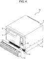
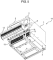
- FIGS. 4 and 5 are perspective views of commercial heat cooking device 10 according to this exemplary embodiment, where front grille panel 12 provided on the front face side of machine chamber 2 is removed.
- FIG. 4 is a perspective view when viewed obliquely from upper right
- FIG. 5 is a perspective view when viewed obliquely from lower right.
- Front grille panel 12 configuring an exterior on a lower portion of a front face side of heat cooking device 10 is detachable with respect to machine chamber 2.
- On a front face of front grille panel 12 a plurality of plate materials is provided in parallel in a vertical direction so as to have a predetermined gap and to face obliquely downward to take outside air from beneath.
- outside air intake port 13 formed by a plurality of punching holes is provided on the front face of machine chamber 2, when front grille panel 12 is removed.
- the four cooling fans for cooling the inverters, the magnetrons, and other components, and cooling fan 11 for cooling the power supply circuit board are provided in parallel immediately behind outside air intake port 13.
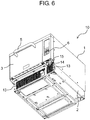
- FIG. 6 is a view of heat cooking device 10 when front grille panel 12 is removed, and when viewed obliquely from below.
- memory card attaching mechanism 15 is provided under operation unit 6 provided on a right side of the front face of main body 1.
- operation unit 6 provided on a right side of the front face of main body 1.
- front grille panel 12 is attached to the front face of machine chamber 2, front grille panel 12 is disposed immediately below operation unit 6 and door 3, and thus memory card attaching mechanism 15 is not exposed from the heat cooking device, and cannot be viewed.
- memory card attaching mechanism 15 is inserted with a smaller memory card, i.e., SD card 14.
- FIG. 7 is an enlarged view of memory card attaching mechanism 15 shown in FIG. 6 .
- SD card 14 is about to be inserted into card insertion port 16 of memory card attaching mechanism 15.
- memory card attaching mechanism 15 is provided with card insertion port 16 for inserting SD card 14 upward, and card insertion port 16 is provided on a lower face of operation unit 6.
- FIG. 8 is a view when SD card 14 is inserted into card insertion port 16 of memory card attaching mechanism 15. As shown in FIG. 8 , although SD card 14 is projecting somewhat from card insertion port 16, a recess formed around card insertion port 16 surrounds projecting SD card 14. Therefore, while SD card 14 is inserted into memory card attaching mechanism 15, SD card 14 does not substantially project from the lower face of operation unit 6.
- card cover 17 attached so as to cover SD card 14 after SD card 14 is inserted is provided.
- Card cover 17 is fixed to memory card attaching mechanism 15 with an easily removable fastener such as screw 18 to cover and securely seal card insertion port 16 into which SD card 14 is inserted from beneath. Therefore, SD card 14 is configured so as to neither be easily accessed nor removed, as well as card insertion port 16 is configured so as to securely prevent foreign materials including dust and dirt from entering.
- FIG. 9 is a side cross-sectional view of memory card attaching mechanism 15 according to this exemplary embodiment, when SD card 14 inserted into memory card attaching mechanism 15 is viewed from left.
- FIG. 9 illustrates a state in which SD card 14 is inserted into memory card attaching mechanism 15, but card cover 17 is not attached yet.
- the side cross-sectional view shown in FIG. 10 illustrates a state, in which card cover 17 is attached to memory card attaching mechanism 15, shifted from the state shown in FIG. 9 .
- card cover 17 is configured to be rotatable about hinge 17a.
- Card cover 17 includes curved portion 17b formed to detour a part of the housing, which lies on a lower end (lower face) of operation unit 6, and fixing portion 17c covering and sealing card insertion port 16 from beneath.
- Fixing portion 17c of card cover 17 is provided with a fastener, i.e., screw 18, and fixing portion 17c is configured to securely cover card insertion port 16 of memory card attaching mechanism 15.
- Memory card attaching mechanism 15 includes lower face wall 21 of operation unit 6, on which card insertion port 16 is formed, SD card connector 19 that is electrically connected to a control circuit and that accepts SD card 14, and base 20 for holding SD card connector 19 in an inner space of operation unit 6.
- Card cover 17 is attached to lower face wall 21 of operation unit 6, on which card insertion port 16 is formed, to substantially configure the lower face of operation unit 6.
- an attaching face of base 20, onto which SD card connector 19 is fixed is a vertical face in the inner space of operation unit 6 such that an insertion direction of SD card connector 19 is vertically upward.
- SD card connector 19 is configured to be fixed to base 20 such that a flat face of SD card 14 being inserted is in parallel to the mounting face (flat face) of the electric circuit board (control circuit board) provided in operation unit 6. Therefore, in operation unit 6, SD card connector 19 can be provided using base 20, similar to other electric circuit boards, without providing a special member, and thus the inner space of operation unit 6 can effectively be used.
- the commercial heat cooking device according to this exemplary embodiment is configured to be capable of reducing a space for providing memory card attaching mechanism 15. The feature contributes to a reduction in whole device size.
- the inner space of operation unit 6 is disposed via an insulation member to have a predetermined space with respect to heating chamber 4, and a member to be heated to a high temperature is not provided, SD card connector 19 will not be subject to a high temperature. Since a member that generates greater noise is not provided, as well as a wiring distance from SD card connector 19 to the control circuit is shorter, the inner space of operation unit 6 has a configuration in which an error would be less likely to occur in obtaining information from SD card 14 inserted into memory card attaching mechanism 15.
- the heat cooking device is configured such that the memory card attaching mechanism having card insertion port 16 into which a memory card is to be inserted is hidden by front grille panel 12 detachably attached on the front face side of machine chamber 2, and thus cannot be viewed externally from the heat cooking device. Therefore, when exchanging a memory card, front grille panel 12 and card cover 17 provided on the lower face side of operation unit 6 should be removed to access card insertion port 16.
- Card insertion port 16 is provided on the lower face of operation unit 6, and is configured to be inserted with a memory card vertically upward to attach the memory card into the memory card attaching mechanism. Therefore, card insertion port 16 is surrounded by the recess on lower face wall 21 of operation unit 6, is disposed downward, and is structured to prevent water from entering. Thus, a structure with a water-proof feature is not required for card insertion port 16 and a memory card connector (SD card connector 19).
- the memory card attaching mechanism has an external configuration that can neither easily be viewed externally, nor easily be accessed by a third party.
- the commercial heat cooking device according to this exemplary embodiment is configured such that foreign materials including dust and dirt would be less likely to enter, and so as not to be subject to a high temperature.
- a simple, reliable heat cooking device without requiring a special waterproof measure is provided.
- the present disclosure has a configuration applicable to heat cooking devices for heating and cooking an object, and in particular to heat cooking devices such as commercial microwave ovens used in, for example, stores and restaurants, in particular, used in convenience stores and fast-food restaurants.
Landscapes
- Engineering & Computer Science (AREA)
- Physics & Mathematics (AREA)
- Electromagnetism (AREA)
- Human Computer Interaction (AREA)
- Chemical & Material Sciences (AREA)
- Combustion & Propulsion (AREA)
- Mechanical Engineering (AREA)
- General Engineering & Computer Science (AREA)
- Electric Ovens (AREA)
Claims (5)
- Dispositif de cuisson thermique (10) comprenant :un corps principal (1) comportant une chambre de chauffe (4) destiné à loger et chauffer un objet ;une chambre de machine (2) disposée sous le corps principal, la chambre de machine étant équipée d'un mécanisme destiné à former et transmettre des micro-ondes pour un chauffage par micro-ondes dans la chambre de chauffe ;un panneau de calandre avant (12) disposé de manière amovible sur une face avant de la chambre de machine ;une porte (3) conçue pour pouvoir être ouverte par rapport à la chambre de chauffe ; etun mécanisme d'attache de carte mémoire (15) conçu pour insérer une carte mémoire (14) dans le corps principal,caractérisé en ce que le mécanisme d'attache de carte mémoire est conçu pour comporter, sur une face inférieure du corps principal, un port d'insertion de carte (16) permettant d'insérer la carte mémoire verticalement vers le haut, le port d'insertion de carte étant conçu pour être caché par le panneau de calandre avant attaché à la chambre de machine de manière à ne pas être exposé depuis le dispositif de cuisson thermique.
- Dispositif de cuisson thermique selon la revendication 1, dans lequel le port d'insertion de carte du mécanisme d'attache de carte mémoire est disposé sur une face inférieure d'une unité de fonctionnement (6) disposée sur une face avant du corps principal de manière que la carte mémoire insérée dans le mécanisme d'attache de carte mémoire est logée dans l'unité de fonctionnement.
- Dispositif de cuisson thermique selon la revendication 2, dans lequel un cache-carte (17) destiné à recouvrir le port d'insertion de carte par en dessous est monté rotatif.
- Dispositif de cuisson thermique selon la revendication 3, dans lequel l'unité de fonctionnement est conçue intérieurement de manière qu'une face plate de la carte mémoire insérée dans le mécanisme d'attache de carte mémoire est parallèle à une face de montage d'une carte de circuit imprimé électrique disposée dans l'unité de fonctionnement.
- Dispositif de cuisson thermique selon la revendication 4, comprenant en outre un ventilateur de refroidissement (11) conçu pour refroidir des composants de chauffage disposés dans la chambre de machine de manière que l'air extérieur est pris du panneau de calandre avant et placé dans la chambre de machine par le biais d'un port d'admission d'air extérieur (13) formé sur la face avant de la chambre de machine, le mécanisme d'attache de carte mémoire étant disposé à distance d'un trajet dans lequel le ventilateur de refroidissement souffle l'air extérieur.
Applications Claiming Priority (2)
| Application Number | Priority Date | Filing Date | Title |
|---|---|---|---|
| JP2015166742 | 2015-08-26 | ||
| PCT/JP2016/003816 WO2017033457A1 (fr) | 2015-08-26 | 2016-08-23 | Dispositif de cuisson |
Publications (3)
| Publication Number | Publication Date |
|---|---|
| EP3343109A1 EP3343109A1 (fr) | 2018-07-04 |
| EP3343109A4 EP3343109A4 (fr) | 2018-09-12 |
| EP3343109B1 true EP3343109B1 (fr) | 2019-02-27 |
Family
ID=58101190
Family Applications (1)
| Application Number | Title | Priority Date | Filing Date |
|---|---|---|---|
| EP16838807.2A Active EP3343109B1 (fr) | 2015-08-26 | 2016-08-23 | Dispositif de cuisson |
Country Status (7)
| Country | Link |
|---|---|
| US (1) | US10212765B2 (fr) |
| EP (1) | EP3343109B1 (fr) |
| JP (1) | JP6667082B2 (fr) |
| CN (1) | CN107850312B (fr) |
| CA (1) | CA2987557C (fr) |
| HK (1) | HK1246847B (fr) |
| WO (1) | WO2017033457A1 (fr) |
Families Citing this family (6)
| Publication number | Priority date | Publication date | Assignee | Title |
|---|---|---|---|---|
| CN109546450A (zh) * | 2017-09-21 | 2019-03-29 | 富士康(昆山)电脑接插件有限公司 | 电连接器组合及其固定座 |
| JP1599562S (fr) * | 2017-09-28 | 2018-03-12 | ||
| KR102126485B1 (ko) * | 2018-10-23 | 2020-06-24 | 엘지전자 주식회사 | 스팀 공급 장치가 구비된 전자 조리 기기 |
| USD995518S1 (en) | 2021-09-29 | 2023-08-15 | Weber-Stephen Products Llc | Dongle |
| JP7607198B2 (ja) * | 2021-10-04 | 2024-12-27 | パナソニックIpマネジメント株式会社 | 加熱調理器 |
| USD1028607S1 (en) * | 2022-09-07 | 2024-05-28 | Shenzhen Typhur Technology Co., Ltd | Cooking oven |
Family Cites Families (16)
| Publication number | Priority date | Publication date | Assignee | Title |
|---|---|---|---|---|
| US4345132A (en) * | 1978-12-01 | 1982-08-17 | Mitsubishi Denki Kabushiki Kaisha | Cooking apparatus |
| JPS55139310U (fr) * | 1979-03-26 | 1980-10-04 | ||
| JPS56935A (en) * | 1979-06-15 | 1981-01-08 | Matsushita Electric Ind Co Ltd | High-frequency heating device |
| JPS5616267U (fr) * | 1979-07-17 | 1981-02-12 | ||
| US4841125A (en) * | 1985-07-18 | 1989-06-20 | Sharp Kabushiki Kaisha | Control unit for a heating system with memory means |
| JPH05126339A (ja) * | 1991-09-13 | 1993-05-21 | Toshiba Corp | 加熱調理器 |
| US5967021A (en) * | 1994-11-29 | 1999-10-19 | Yung; Simon K. C. | Food appliance and a coding system therefor |
| CN1334422A (zh) * | 2000-07-17 | 2002-02-06 | 海尔集团公司 | Ic卡式微波炉 |
| JP2002349863A (ja) * | 2001-05-30 | 2002-12-04 | Matsushita Electric Ind Co Ltd | 加熱調理器 |
| JP2003074869A (ja) * | 2001-09-04 | 2003-03-12 | Matsushita Electric Ind Co Ltd | 加熱調理器 |
| JP2004212014A (ja) | 2003-01-08 | 2004-07-29 | Matsushita Electric Ind Co Ltd | 高周波加熱装置 |
| JP2008121988A (ja) * | 2006-11-13 | 2008-05-29 | Toshiba Corp | 加熱調理器 |
| DE102007021940B4 (de) * | 2007-05-10 | 2020-10-29 | BSH Hausgeräte GmbH | Hausgeräte mit einer Benutzerschnittstelle |
| TR201011022A1 (tr) * | 2010-12-28 | 2012-07-23 | Arçeli̇k Anoni̇m Şi̇rketi̇ | Taşınabilir bellek girişi içeren bir fırın. |
| CN104132382A (zh) * | 2013-05-03 | 2014-11-05 | 杨淞 | 一种音乐烧烤微波炉 |
| CN103336454A (zh) * | 2013-06-24 | 2013-10-02 | 李文庆 | 一种可快速更新菜单的调理器 |
-
2016
- 2016-08-23 HK HK18106270.8A patent/HK1246847B/zh unknown
- 2016-08-23 CN CN201680041826.XA patent/CN107850312B/zh active Active
- 2016-08-23 US US15/569,581 patent/US10212765B2/en active Active
- 2016-08-23 WO PCT/JP2016/003816 patent/WO2017033457A1/fr not_active Ceased
- 2016-08-23 CA CA2987557A patent/CA2987557C/fr active Active
- 2016-08-23 EP EP16838807.2A patent/EP3343109B1/fr active Active
- 2016-08-23 JP JP2017536616A patent/JP6667082B2/ja active Active
Non-Patent Citations (1)
| Title |
|---|
| None * |
Also Published As
| Publication number | Publication date |
|---|---|
| CN107850312A (zh) | 2018-03-27 |
| US10212765B2 (en) | 2019-02-19 |
| CA2987557C (fr) | 2019-10-01 |
| EP3343109A1 (fr) | 2018-07-04 |
| US20180098389A1 (en) | 2018-04-05 |
| HK1246847B (zh) | 2020-06-05 |
| JP6667082B2 (ja) | 2020-03-18 |
| JPWO2017033457A1 (ja) | 2018-06-14 |
| CN107850312B (zh) | 2019-09-03 |
| CA2987557A1 (fr) | 2017-03-02 |
| WO2017033457A1 (fr) | 2017-03-02 |
| EP3343109A4 (fr) | 2018-09-12 |
Similar Documents
| Publication | Publication Date | Title |
|---|---|---|
| EP3343109B1 (fr) | Dispositif de cuisson | |
| EP1431667B1 (fr) | Four électrique | |
| EP3343110B1 (fr) | Cuiseur | |
| KR20120054847A (ko) | 복합형 전자레인지 | |
| EP1640666A1 (fr) | Appareil de cuisson pouvant servir pour une application integree | |
| HK1246847A1 (en) | Heat cooking device | |
| CN105960830B (zh) | 微波加热装置 | |
| JP3689708B2 (ja) | 加熱調理器 | |
| JP5011001B2 (ja) | 加熱調理器 | |
| KR102938390B1 (ko) | 조리기기 | |
| KR100633173B1 (ko) | 전기오븐의 전장실 구조 | |
| US20220322501A1 (en) | Cooking apparatus | |
| JP2015203518A (ja) | 加熱調理器 | |
| US20250244024A1 (en) | Heating cooker | |
| US20250137661A1 (en) | Heating cooker | |
| JP5057871B2 (ja) | 加熱調理器 | |
| JP2023028543A (ja) | 加熱調理器 | |
| JP2011058674A (ja) | 加熱調理器 | |
| JP2026071790A (ja) | 電子レンジ | |
| JP2016217584A (ja) | 加熱調理器 | |
| JP2017220387A (ja) | 加熱調理器 | |
| HK1242405B (zh) | 加热烹调器 | |
| JP2001132954A (ja) | 加熱調理装置 | |
| HK1242405A1 (en) | Cooker | |
| KR20140109608A (ko) | 조리 기기 |
Legal Events
| Date | Code | Title | Description |
|---|---|---|---|
| STAA | Information on the status of an ep patent application or granted ep patent |
Free format text: STATUS: THE INTERNATIONAL PUBLICATION HAS BEEN MADE |
|
| PUAI | Public reference made under article 153(3) epc to a published international application that has entered the european phase |
Free format text: ORIGINAL CODE: 0009012 |
|
| STAA | Information on the status of an ep patent application or granted ep patent |
Free format text: STATUS: REQUEST FOR EXAMINATION WAS MADE |
|
| 17P | Request for examination filed |
Effective date: 20170928 |
|
| AK | Designated contracting states |
Kind code of ref document: A1 Designated state(s): AL AT BE BG CH CY CZ DE DK EE ES FI FR GB GR HR HU IE IS IT LI LT LU LV MC MK MT NL NO PL PT RO RS SE SI SK SM TR |
|
| AX | Request for extension of the european patent |
Extension state: BA ME |
|
| A4 | Supplementary search report drawn up and despatched |
Effective date: 20180813 |
|
| RIC1 | Information provided on ipc code assigned before grant |
Ipc: F24C 7/08 20060101ALI20180806BHEP Ipc: H05B 6/64 20060101ALI20180806BHEP Ipc: F24C 15/00 20060101ALI20180806BHEP Ipc: F24C 7/02 20060101AFI20180806BHEP |
|
| GRAP | Despatch of communication of intention to grant a patent |
Free format text: ORIGINAL CODE: EPIDOSNIGR1 |
|
| STAA | Information on the status of an ep patent application or granted ep patent |
Free format text: STATUS: GRANT OF PATENT IS INTENDED |
|
| DAV | Request for validation of the european patent (deleted) | ||
| DAX | Request for extension of the european patent (deleted) | ||
| INTG | Intention to grant announced |
Effective date: 20181116 |
|
| GRAS | Grant fee paid |
Free format text: ORIGINAL CODE: EPIDOSNIGR3 |
|
| GRAA | (expected) grant |
Free format text: ORIGINAL CODE: 0009210 |
|
| STAA | Information on the status of an ep patent application or granted ep patent |
Free format text: STATUS: THE PATENT HAS BEEN GRANTED |
|
| AK | Designated contracting states |
Kind code of ref document: B1 Designated state(s): AL AT BE BG CH CY CZ DE DK EE ES FI FR GB GR HR HU IE IS IT LI LT LU LV MC MK MT NL NO PL PT RO RS SE SI SK SM TR |
|
| REG | Reference to a national code |
Ref country code: GB Ref legal event code: FG4D |
|
| REG | Reference to a national code |
Ref country code: CH Ref legal event code: EP |
|
| REG | Reference to a national code |
Ref country code: AT Ref legal event code: REF Ref document number: 1101911 Country of ref document: AT Kind code of ref document: T Effective date: 20190315 |
|
| REG | Reference to a national code |
Ref country code: IE Ref legal event code: FG4D |
|
| REG | Reference to a national code |
Ref country code: DE Ref legal event code: R096 Ref document number: 602016010517 Country of ref document: DE |
|
| REG | Reference to a national code |
Ref country code: NL Ref legal event code: MP Effective date: 20190227 |
|
| REG | Reference to a national code |
Ref country code: LT Ref legal event code: MG4D |
|
| PG25 | Lapsed in a contracting state [announced via postgrant information from national office to epo] |
Ref country code: SE Free format text: LAPSE BECAUSE OF FAILURE TO SUBMIT A TRANSLATION OF THE DESCRIPTION OR TO PAY THE FEE WITHIN THE PRESCRIBED TIME-LIMIT Effective date: 20190227 Ref country code: PT Free format text: LAPSE BECAUSE OF FAILURE TO SUBMIT A TRANSLATION OF THE DESCRIPTION OR TO PAY THE FEE WITHIN THE PRESCRIBED TIME-LIMIT Effective date: 20190627 Ref country code: NL Free format text: LAPSE BECAUSE OF FAILURE TO SUBMIT A TRANSLATION OF THE DESCRIPTION OR TO PAY THE FEE WITHIN THE PRESCRIBED TIME-LIMIT Effective date: 20190227 Ref country code: LT Free format text: LAPSE BECAUSE OF FAILURE TO SUBMIT A TRANSLATION OF THE DESCRIPTION OR TO PAY THE FEE WITHIN THE PRESCRIBED TIME-LIMIT Effective date: 20190227 Ref country code: NO Free format text: LAPSE BECAUSE OF FAILURE TO SUBMIT A TRANSLATION OF THE DESCRIPTION OR TO PAY THE FEE WITHIN THE PRESCRIBED TIME-LIMIT Effective date: 20190527 Ref country code: FI Free format text: LAPSE BECAUSE OF FAILURE TO SUBMIT A TRANSLATION OF THE DESCRIPTION OR TO PAY THE FEE WITHIN THE PRESCRIBED TIME-LIMIT Effective date: 20190227 |
|
| PG25 | Lapsed in a contracting state [announced via postgrant information from national office to epo] |
Ref country code: IS Free format text: LAPSE BECAUSE OF FAILURE TO SUBMIT A TRANSLATION OF THE DESCRIPTION OR TO PAY THE FEE WITHIN THE PRESCRIBED TIME-LIMIT Effective date: 20190627 Ref country code: BG Free format text: LAPSE BECAUSE OF FAILURE TO SUBMIT A TRANSLATION OF THE DESCRIPTION OR TO PAY THE FEE WITHIN THE PRESCRIBED TIME-LIMIT Effective date: 20190527 Ref country code: RS Free format text: LAPSE BECAUSE OF FAILURE TO SUBMIT A TRANSLATION OF THE DESCRIPTION OR TO PAY THE FEE WITHIN THE PRESCRIBED TIME-LIMIT Effective date: 20190227 Ref country code: LV Free format text: LAPSE BECAUSE OF FAILURE TO SUBMIT A TRANSLATION OF THE DESCRIPTION OR TO PAY THE FEE WITHIN THE PRESCRIBED TIME-LIMIT Effective date: 20190227 Ref country code: GR Free format text: LAPSE BECAUSE OF FAILURE TO SUBMIT A TRANSLATION OF THE DESCRIPTION OR TO PAY THE FEE WITHIN THE PRESCRIBED TIME-LIMIT Effective date: 20190528 Ref country code: HR Free format text: LAPSE BECAUSE OF FAILURE TO SUBMIT A TRANSLATION OF THE DESCRIPTION OR TO PAY THE FEE WITHIN THE PRESCRIBED TIME-LIMIT Effective date: 20190227 |
|
| REG | Reference to a national code |
Ref country code: AT Ref legal event code: MK05 Ref document number: 1101911 Country of ref document: AT Kind code of ref document: T Effective date: 20190227 |
|
| PG25 | Lapsed in a contracting state [announced via postgrant information from national office to epo] |
Ref country code: IT Free format text: LAPSE BECAUSE OF FAILURE TO SUBMIT A TRANSLATION OF THE DESCRIPTION OR TO PAY THE FEE WITHIN THE PRESCRIBED TIME-LIMIT Effective date: 20190227 Ref country code: SK Free format text: LAPSE BECAUSE OF FAILURE TO SUBMIT A TRANSLATION OF THE DESCRIPTION OR TO PAY THE FEE WITHIN THE PRESCRIBED TIME-LIMIT Effective date: 20190227 Ref country code: AL Free format text: LAPSE BECAUSE OF FAILURE TO SUBMIT A TRANSLATION OF THE DESCRIPTION OR TO PAY THE FEE WITHIN THE PRESCRIBED TIME-LIMIT Effective date: 20190227 Ref country code: DK Free format text: LAPSE BECAUSE OF FAILURE TO SUBMIT A TRANSLATION OF THE DESCRIPTION OR TO PAY THE FEE WITHIN THE PRESCRIBED TIME-LIMIT Effective date: 20190227 Ref country code: EE Free format text: LAPSE BECAUSE OF FAILURE TO SUBMIT A TRANSLATION OF THE DESCRIPTION OR TO PAY THE FEE WITHIN THE PRESCRIBED TIME-LIMIT Effective date: 20190227 Ref country code: ES Free format text: LAPSE BECAUSE OF FAILURE TO SUBMIT A TRANSLATION OF THE DESCRIPTION OR TO PAY THE FEE WITHIN THE PRESCRIBED TIME-LIMIT Effective date: 20190227 Ref country code: CZ Free format text: LAPSE BECAUSE OF FAILURE TO SUBMIT A TRANSLATION OF THE DESCRIPTION OR TO PAY THE FEE WITHIN THE PRESCRIBED TIME-LIMIT Effective date: 20190227 Ref country code: RO Free format text: LAPSE BECAUSE OF FAILURE TO SUBMIT A TRANSLATION OF THE DESCRIPTION OR TO PAY THE FEE WITHIN THE PRESCRIBED TIME-LIMIT Effective date: 20190227 |
|
| REG | Reference to a national code |
Ref country code: DE Ref legal event code: R097 Ref document number: 602016010517 Country of ref document: DE |
|
| PG25 | Lapsed in a contracting state [announced via postgrant information from national office to epo] |
Ref country code: SM Free format text: LAPSE BECAUSE OF FAILURE TO SUBMIT A TRANSLATION OF THE DESCRIPTION OR TO PAY THE FEE WITHIN THE PRESCRIBED TIME-LIMIT Effective date: 20190227 Ref country code: PL Free format text: LAPSE BECAUSE OF FAILURE TO SUBMIT A TRANSLATION OF THE DESCRIPTION OR TO PAY THE FEE WITHIN THE PRESCRIBED TIME-LIMIT Effective date: 20190227 |
|
| PG25 | Lapsed in a contracting state [announced via postgrant information from national office to epo] |
Ref country code: AT Free format text: LAPSE BECAUSE OF FAILURE TO SUBMIT A TRANSLATION OF THE DESCRIPTION OR TO PAY THE FEE WITHIN THE PRESCRIBED TIME-LIMIT Effective date: 20190227 |
|
| PLBE | No opposition filed within time limit |
Free format text: ORIGINAL CODE: 0009261 |
|
| STAA | Information on the status of an ep patent application or granted ep patent |
Free format text: STATUS: NO OPPOSITION FILED WITHIN TIME LIMIT |
|
| 26N | No opposition filed |
Effective date: 20191128 |
|
| PG25 | Lapsed in a contracting state [announced via postgrant information from national office to epo] |
Ref country code: TR Free format text: LAPSE BECAUSE OF FAILURE TO SUBMIT A TRANSLATION OF THE DESCRIPTION OR TO PAY THE FEE WITHIN THE PRESCRIBED TIME-LIMIT Effective date: 20190227 |
|
| PG25 | Lapsed in a contracting state [announced via postgrant information from national office to epo] |
Ref country code: LU Free format text: LAPSE BECAUSE OF NON-PAYMENT OF DUE FEES Effective date: 20190823 Ref country code: CH Free format text: LAPSE BECAUSE OF NON-PAYMENT OF DUE FEES Effective date: 20190831 Ref country code: MC Free format text: LAPSE BECAUSE OF FAILURE TO SUBMIT A TRANSLATION OF THE DESCRIPTION OR TO PAY THE FEE WITHIN THE PRESCRIBED TIME-LIMIT Effective date: 20190227 Ref country code: LI Free format text: LAPSE BECAUSE OF NON-PAYMENT OF DUE FEES Effective date: 20190831 |
|
| REG | Reference to a national code |
Ref country code: BE Ref legal event code: MM Effective date: 20190831 |
|
| PG25 | Lapsed in a contracting state [announced via postgrant information from national office to epo] |
Ref country code: FR Free format text: LAPSE BECAUSE OF NON-PAYMENT OF DUE FEES Effective date: 20190831 Ref country code: IE Free format text: LAPSE BECAUSE OF NON-PAYMENT OF DUE FEES Effective date: 20190823 |
|
| PG25 | Lapsed in a contracting state [announced via postgrant information from national office to epo] |
Ref country code: BE Free format text: LAPSE BECAUSE OF NON-PAYMENT OF DUE FEES Effective date: 20190831 |
|
| PG25 | Lapsed in a contracting state [announced via postgrant information from national office to epo] |
Ref country code: CY Free format text: LAPSE BECAUSE OF FAILURE TO SUBMIT A TRANSLATION OF THE DESCRIPTION OR TO PAY THE FEE WITHIN THE PRESCRIBED TIME-LIMIT Effective date: 20190227 |
|
| PG25 | Lapsed in a contracting state [announced via postgrant information from national office to epo] |
Ref country code: MT Free format text: LAPSE BECAUSE OF FAILURE TO SUBMIT A TRANSLATION OF THE DESCRIPTION OR TO PAY THE FEE WITHIN THE PRESCRIBED TIME-LIMIT Effective date: 20190227 Ref country code: HU Free format text: LAPSE BECAUSE OF FAILURE TO SUBMIT A TRANSLATION OF THE DESCRIPTION OR TO PAY THE FEE WITHIN THE PRESCRIBED TIME-LIMIT; INVALID AB INITIO Effective date: 20160823 |
|
| PG25 | Lapsed in a contracting state [announced via postgrant information from national office to epo] |
Ref country code: SI Free format text: LAPSE BECAUSE OF FAILURE TO SUBMIT A TRANSLATION OF THE DESCRIPTION OR TO PAY THE FEE WITHIN THE PRESCRIBED TIME-LIMIT Effective date: 20190227 |
|
| PG25 | Lapsed in a contracting state [announced via postgrant information from national office to epo] |
Ref country code: MK Free format text: LAPSE BECAUSE OF FAILURE TO SUBMIT A TRANSLATION OF THE DESCRIPTION OR TO PAY THE FEE WITHIN THE PRESCRIBED TIME-LIMIT Effective date: 20190227 |
|
| PGFP | Annual fee paid to national office [announced via postgrant information from national office to epo] |
Ref country code: DE Payment date: 20250820 Year of fee payment: 10 |
|
| PGFP | Annual fee paid to national office [announced via postgrant information from national office to epo] |
Ref country code: GB Payment date: 20250821 Year of fee payment: 10 |