EP3343122B1 - Lufteinlass oder -auslass - Google Patents
Lufteinlass oder -auslass Download PDFInfo
- Publication number
- EP3343122B1 EP3343122B1 EP17205486.8A EP17205486A EP3343122B1 EP 3343122 B1 EP3343122 B1 EP 3343122B1 EP 17205486 A EP17205486 A EP 17205486A EP 3343122 B1 EP3343122 B1 EP 3343122B1
- Authority
- EP
- European Patent Office
- Prior art keywords
- pipe
- vent
- vent according
- longitudinal axis
- faceplate
- Prior art date
- Legal status (The legal status is an assumption and is not a legal conclusion. Google has not performed a legal analysis and makes no representation as to the accuracy of the status listed.)
- Active
Links
Images


Classifications
-
- F—MECHANICAL ENGINEERING; LIGHTING; HEATING; WEAPONS; BLASTING
- F24—HEATING; RANGES; VENTILATING
- F24F—AIR-CONDITIONING; AIR-HUMIDIFICATION; VENTILATION; USE OF AIR CURRENTS FOR SCREENING
- F24F13/00—Details common to, or for air-conditioning, air-humidification, ventilation or use of air currents for screening
- F24F13/02—Ducting arrangements
- F24F13/06—Outlets for directing or distributing air into rooms or spaces, e.g. ceiling air diffuser
- F24F13/062—Outlets for directing or distributing air into rooms or spaces, e.g. ceiling air diffuser having one or more bowls or cones diverging in the flow direction
-
- F—MECHANICAL ENGINEERING; LIGHTING; HEATING; WEAPONS; BLASTING
- F24—HEATING; RANGES; VENTILATING
- F24F—AIR-CONDITIONING; AIR-HUMIDIFICATION; VENTILATION; USE OF AIR CURRENTS FOR SCREENING
- F24F13/00—Details common to, or for air-conditioning, air-humidification, ventilation or use of air currents for screening
- F24F13/02—Ducting arrangements
- F24F13/06—Outlets for directing or distributing air into rooms or spaces, e.g. ceiling air diffuser
Definitions
- the invention relates to an air extraction or blowing mouth.
- vents are connected to ventilation units or other equipment for extracting or blowing air into the building to be treated by means of ducts.
- ventilation systems in particular centralized ventilation systems of the controlled mechanical ventilation type, often installed in the attic or roof terraces, are visible in the housing by these mouths that aesthetically mask the air inlet or outlet. .
- vents can integrate additional functions, for example an orientation of the airflow by means of flaps, a control of a constant flow, a modulation of the flow according to the hygrometry of the room or a modulation of the flow in function a presence in the room.
- the patent document KR 20-2015-0003460 discloses a mouth having a duct intended to be arranged in a wall and provided with a support flange on the wall, an outer front face plate having a front surface greater than the internal section of the duct and supporting the end of a central shaft also supported by the duct and on which can slide a tray of modulation of the air flow through the mouth.
- This mouth however allows only one level of flow, in its open position.
- the invention solves these problems by proposing an air extraction or blowing mouth which ensures two levels of flow while limiting the pressure losses and which is of limited size, of optimal aesthetics since it does not have any air passage port visible from the outside and excellent mechanical stability, while being particularly simple manufacturing.
- an air extraction or insufflation mouth comprising a duct intended to be disposed in an orifice of a wall and provided with a radial support flange on said wall, a plate a facade integral with said duct and an air flow modulation element movable from an open position to a closed position of the air flow exiting from or entering the mouth between said radial support flange of the duct and said air intake plate; frontage, by axial displacement along the longitudinal axis of said duct, mouth characterized in that said modulation element comprises two airflow guide portions, front and rear, tubular longitudinal axis parallel to the longitudinal axis of said duct, these two guide portions being able to ensure the passage of the flow of air exiting from or entering the mouth between said radial support flange of the duct and said front plate in the open position and a channel disposed between the s two guide portions being adapted to ensure the passage of the flow of air exiting from or entering the mouth between said radial support flange of
- the tubular constitution of the guide portions ensures an optimal space saving in the thickness of the mouth.
- This arrangement also ensures a mechanical robustness of all the parts constituting the mouth.
- the pressure drop in the open position is greatly reduced, which can reduce the operating pressure of the ventilation unit, and thus the noise and consumption generated.
- guide portion it is understood a portion actually cutting the air stream in two parts, continuous and preferably not perforated in the air path.
- the two said air flow guide portions, front and rear, tubular are of the same longitudinal axis as said conduit.
- the two said air flow guide portions, front and rear, tubular are radially flared curve generator.
- curve generator is meant the general shape of the guide parts. Potentially, amenities can be placed at specific locations.
- This shape of the guiding portions ensures optimum guidance of the air flow exiting from or entering the mouth between the radial support flange of the duct and said facade plate and reduces the pressure losses.
- it comprises a drive actuator of said modulation element held between the rear face of said facade plate and said modulation element.
- said modulation element comprises a rear tubular portion having the same longitudinal axis as said straight duct and generator, carrying an external thread and movable from said open position to said closed position, by rotation of this thread in an internal thread of said duct. .
- Said tapping may be discontinuous, to ensure a good demoldability and to limit the friction problems related to geometric defects.
- this tapping can also be continuous if one wishes even more to limit the pressure drops and the leak passing through this tapping. On the other hand, it is more difficult to manufacture.
- said duct carries on its inner face a stop pin in axial displacement cooperating with the rear end of said rear tubular portion, in the closed position.
- said front guide portion comprises a tubular front drive portion of the same longitudinal axis as said conduit and right generator, this driving portion being intended to be driven by said actuator.
- said drive portion preferably comprises an internal toothing cooperating with a gear connected to said actuator which is a rotary electric motor, this gear having a height strictly greater than the displacement amplitude of said modulation element.
- the front end of said modulation element may comprise at least one tooth providing a stop locked in rotation with at least one corresponding tooth arranged on said front plate.
- the front end of said front guide portion is in substantially sealing abutment against said radial support flange, in the closed position.
- said modulation element comprises a rear tubular support portion having the same longitudinal axis as said duct and generator right, and sliding by translation on the inner face of the duct.
- said drive actuator of said modulation element is integral with said front plate or said radial support flange and said modulation element comprises a tapping or a rack cooperating with a screw connected to said actuator which is a rotary engine, this tapping, this rack or this screw having a height strictly greater than the displacement amplitude of said modulation element.
- the tapping may alternatively be replaced by one or more rack type connections or equivalent.
- said drive actuator is connected to an endless screw axially substantially perpendicular to the longitudinal axis of said conduit, which it drives in rotation and on which is moved a nut connected by a first articulated lever to said front plate and a second lever articulated to said modulation element.
- the mouth is preferably equipped with at least one energy recovery device at least partially ensuring its self-power supply and providing an electrical signal and in that it comprises an electronic processing device of said electrical signal.
- the mouth can also be powered by replaceable batteries or by a wire feed from a ventilation group.
- said energy recovery device comprises a turbine disposed within said rear guide portion, at the rear of said front guide portion, said turbine being connected to a generator transforming its mechanical rotational energy into said electrical signal correlated to the flow of air passing through the mouth.
- the energy recovery device may also be a solar panel capturing the lighting of the room to be ventilated, the photovoltaic cell of which is preferably placed on the visible face of the facade plate.
- Said turbine is preferably a helical turbine whose axis of rotation is substantially parallel to the longitudinal axis of said duct.
- said facade plate has a front surface greater than the inner section of said duct.
- Said facade plate preferably has its smallest frontal dimension greater than the maximum diameter of said flange of said duct.
- a control device of said actuator may be included on a printed circuit board on said mouth.
- This control device is advantageously controlled according to the state of a sensor connected to said printed circuit and / or according to a flow measurement in the sheath in fluid communication with the mouth and / or according to a control instruction provided by the user.
- the invention also relates to a ventilation installation provided with a fan and a ductwork network, comprising at least one such mouth in air communication with said network and said fan.
- the Figures 1 to 4 represent a first embodiment of a mouth according to the invention.
- This mouth of extraction or air insufflation comprises a conduit 1 intended to be disposed in an orifice of a wall and provided with a radial flange 1A support on the wall, a front plate 2 secured to the duct 1 and an air flow modulation element 3 movable from an open position to a closed position of the flow of air exiting from or entering the mouth between the radial support flange 1A of the duct and the front plate 2 , by axial displacement along the longitudinal axis A of the duct.
- the face plate 2 has a front surface greater than the inner section of the duct 1 and advantageously has its smallest frontal dimension greater than the maximum diameter of said flange 1A of said duct.
- a ventilation installation provided with a fan and a network of ducts, comprises at least one such mouth in air communication with the network and the fan.
- the modulation element 3 comprises two air flow guiding parts 3A and 3B, tubular longitudinal axis parallel to the longitudinal axis A of the duct, these two guide portions being able to ensure the passage of the duct. airflow coming out of or entering the between the flange 1A of the duct support and the face plate 2 in the open position ( figure 3 ) and a channel 3C disposed between the two guide portions 3A, 3B being adapted to ensure the passage of the flow of air exiting from or entering the mouth between the radial support flange 1A of the duct and the front plate 2, in an intermediate position ( figure 2 ) between the open position and said closed position.
- the two so-called airflow guide portions, 3A front and rear 3B, tubular are of the same longitudinal axis A as the radially flared curve and generatrix duct.
- the mouth comprises a drive actuator 4 of the modulation element 3 held between the rear face of the front plate 2 and the modulation element 3.
- the modulation element 3 comprises a rear tubular portion 3D of the same longitudinal axis A as the duct 1 and of the right generator, carrying an external thread 3E and movable from the open position to the closed position, by rotation of this thread 3E in a internal tapping 1B discontinuous duct.
- the duct 1 carries on its inner face a stop pin in axial displacement and in rotation 1F cooperating with a corresponding pin of the rear end of the rear tubular portion, in the closed position.
- This rear tubular portion 3D is also a rear tubular support portion of the guide portions 3A, 3B via 3D1 columns connecting these guide portions 3A, 3B with each other and with this rear portion.
- These 3D1 columns can be three in number, evenly distributed around the periphery of the guide portions 3A, 3B.
- the front guide portion 3A comprises a tubular front drive portion 3G having the same longitudinal axis A as the straight generator duct, this driving portion being intended to be driven by the actuator 4.
- This drive portion 3G has an internal toothing 3H cooperating with a gear 6 connected to the actuator 4 which is a rotary electric motor.
- the front end of the drive part 3G comprises at least one tooth 3I providing an abutment locked in rotation with at least one corresponding tooth 2A 2A arranged on the front plate 2, and this, for the open position.
- the mouth is also equipped with at least one energy recovery device at least partially ensuring its self-power supply and providing an electrical signal and comprises an electronic processing device of this electrical signal.
- this energy recovery device comprises a helical turbine 7 whose axis of rotation is substantially parallel to the longitudinal axis A of the duct, disposed within the rear guide portion 3B, to the rear of the front guide portion 3A, and the turbine 7 is connected to a generator 8 transforming its mechanical rotational energy into the electrical signal correlated to the air flow through the mouth.
- This correlation can be improved by adding a value representing the position of the modulation element.
- a control device of the actuator 4 is included on or connected to a printed circuit (not shown) embedded on said mouth and is controlled according to the state of a sensor connected to said printed circuit and / or according to a measurement of flow in the sheath in fluid communication with the mouth and / or according to a control instruction provided by the user.
- the sensor can be an IAQ sensor (acronym for Indoor Air Quality) or in particular hygrometry, presence detection or other, the user's instruction can be given by wire or radio indicating a level of given opening or a desired mode of operation.
- the turbine 7 is arranged to be in the air flow passing through the channel 3C, in the intermediate position and in the open position. In the open position, the flow of air flowing at the rear of the rear guide portion 3B bypasses the turbine 7, thus reducing the pressure drops and limiting the speed of rotation of the turbine.
- the turbine it can also be envisaged to arrange the turbine, so that it is in the air flow passing through the channel 3C and also in the flow of air flowing at the rear of the rear guide portion 3B.
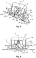
- FIGS. 5 to 13 represent a second embodiment of a mouth according to the invention.
- the modulation element 30 comprises a rear support tubular portion 30D having the same longitudinal axis A as the duct 10, and generator right, and sliding on the inner face of the conduit, in a simple translation parallel to the axis A.
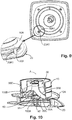
- This support portion 30D carries two airflow guide portions, 30A and 30B front, tubular longitudinal axis to the longitudinal axis A of the conduit 10, the support portion having 30D2 orifices adapted to ensure the passage the flow of air exiting from or entering the mouth between the radial support flange 10A of the duct and the face plate 20 towards the guide portions 30A, 30B, in the open position ( figure 7 ), and to a channel 30C disposed between the two guide parts, in an intermediate position ( figure 6 ) between the open position and said closed position.
- the front end of the modulation element 30, and more precisely of the front guide portion 30A comprises at least one interlocking notch 30A1 with a fixed portion of the facade plate 20. More specifically, the frontage 20 is integral with the duct 10 by means of feet 20A carried by the rear of this face plate and screwed and this fixed part of the front plate 20 is one of these feet 20A whose longitudinal flange 20A1 is fitted in this notch 30A1.
- the drive actuator 40 of the modulation element 30 is integral with the front plate 20 and the modulation element 30 comprises a tapping 70 cooperating with a screw 60 connected to the actuator 40 which is a rotary motor, this tapping 70 or this screw having a height strictly greater than the displacement amplitude of said modulation element 30.
- this internal thread 70 consists of a threaded section protruding forward of the front guide portion 30A.
- a control device of the actuator 40 is included on a printed circuit board on said mouth and is controlled according to the state of a sensor connected to said printed circuit and / or according to a flow measurement in the sheath in communication with fluid with the mouth and / or according to a control instruction provided by the user.
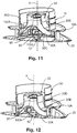
- the drive actuator 40 ' is connected to a worm 80 of axis substantially perpendicular to the longitudinal axis of said conduit, which it rotates and on which is moved a nut 90 connected by a first lever 100A articulated to the front plate 20 and a second lever 100B articulated to the modulation element 30 and more specifically to the front guide portion 30A.
- the part carrying the actuator 40 'and the worm 80 also carries a third lever 100C hinged to the front plate 20 and a fourth lever 100D hinged to said modulation element 30 and more precisely to the front guide portion 30A, so to strengthen the mechanical strength.
- a control device of the actuator 40 ' is included on a printed circuit board on said mouth and is slaved according to the state of a sensor connected to said printed circuit and / or according to a measurement of flow in the sheath in communication fluid with the mouth and / or according to a user-provided control command.
- the turbine is arranged to be in the air flow passing through the channel 30C, in the intermediate position and in the open position.
- the open position the flow of air flowing at the rear of the rear guide portion 30B bypasses the turbine, thus reducing the pressure drops and limiting the speed of rotation of the turbine.
- the front guide portions 3A, 30A and rear 3B, 30B may be of different shapes not necessarily circular, to fit a general shape of the mouth or take into account.
- the size of a component used in the kinematics may be variable according to different criteria, for example compromise between pressure drop, air speed at the turbine, to optimize the starting speed of the turbine or limit its maximum speed, more precise modulation zones, acoustic consideration ...
Landscapes
- Engineering & Computer Science (AREA)
- Chemical & Material Sciences (AREA)
- Combustion & Propulsion (AREA)
- Mechanical Engineering (AREA)
- General Engineering & Computer Science (AREA)
- Air-Flow Control Members (AREA)
- Structures Of Non-Positive Displacement Pumps (AREA)
Claims (22)
- Luftauslass oder -einlass, aufweisend eine Leitung (1, 10), die bestimmt ist, in einer Öffnung einer Wand angeordnet und mit einem radialen Stützflansch (1A, 10A) auf der Wand, einer mit der Leitung (1, 10) fest verbundenen Fassadenplatte (2, 20) und einem Modulationselement des Luftdurchsatzes (3, 30) versehen zu sein, das von einer geöffneten Position in eine geschlossenen Position des aus dem oder in den Aus-/Einlass zwischen dem radialen Stützflansch (1A, 10A) der Leitung und der Fassadenplatte (2, 20) aus- oder eintretenden Luftstrom durch axiale Verlagerung entlang der Längsachse (A) der Leitung beweglich ist, wobei der Aus-/Einlass dadurch gekennzeichnet ist, dass das Modulationselement (3, 30) zwei rohrförmige Führungsabschnitte des Luftstroms, einen vorderen (3A, 30A) und einen hinteren (3B, 30B), mit einer Längsachse parallel zur Längsachse (A) der Leitung aufweist, wobei diese zwei Führungsabschnitte imstande sind, den Durchgang des aus dem oder in den Aus-/Einlass zwischen dem radialen Stützflansch (1A, 10A) der Leitung und der Fassadenplatte (2, 20) in geöffneter Position aus- oder eintretenden Luftstrom zu gewährleisten und einen Kanal (3C, 30C), der zwischen den zwei Führungsabschnitten angeordnet ist, der imstande ist, den Durchgang des aus dem oder in den Aus-/Einlass zwischen dem radialen Stützflansch (1A, 10A) der Leitung und der Fassadenplatte (2, 20) in einer Übergangsposition zwischen der geöffneten Position und der geschlossenen Position aus- oder eintretenden Luftstroms zu gewährleisten.
- Aus-/Einlass nach vorangehendem Anspruch, dadurch gekennzeichnet, dass die zwei rohrförmigen Führungsabschnitte des Luftstroms, der vordere (3A, 30A) und hintere (3B, 30B), dieselbe Längsachse (A) wie die Leitung (1, 10) haben.
- Aus-/Einlass nach Anspruch 1 oder 2, dadurch gekennzeichnet, dass die zwei rohrförmigen Führungsabschnitte des Luftstroms, der vordere (3A, 30A) und hintere (3B, 30B), eine radial erweiterte gekrümmte Mantellinie haben.
- Aus-/Einlass nach einem der vorangehenden Ansprüche, dadurch gekennzeichnet, dass er ein Antriebsstellglied (4, 40, 40') des Modulationselements (3, 30) aufweist, welches zwischen der hinteren Fläche der Fassadenplatte (2, 20) und dem Modulationselement (3, 30) gehalten wird.
- Aus-/Einlass nach einem der vorangehenden Ansprüche, dadurch gekennzeichnet, dass das Modulationselement (3) einen hinteren rohrförmigen Abschnitt (3D) mit derselben Längsachse (A) wie die Leitung und mit gerader Mantellinie aufweist, der ein Außengewinde (3E) trägt und von der geöffneten Position in die geschlossene Position durch Rotation dieses Gewindes (3E) in einem Innengewinde (1B) der Leitung beweglich ist.
- Aus-/Einlass nach vorangehendem Anspruch, dadurch gekennzeichnet, dass das Gewinde (1B) diskontinuierlich ist.
- Aus-/Einlass nach Anspruch 5 oder 6, dadurch gekennzeichnet, dass die Leitung (1) auf ihrer inneren Fläche einen Anschlagstift (1F) in axialer Verlagerung trägt, der mit dem hinteren Ende des hinteren rohrförmigen Abschnitts (3D) zusammenwirkt, in geschlossener Position.
- Aus-/Einlass nach Anspruch 4, dadurch gekennzeichnet, dass der vordere Führungsabschnitt avant (3A) einen rohrförmigen vorderen Antriebsabschnitt (3G) mit derselben Längsachse (A) wie die Leitung (1) und mit gerader Mantellinie aufweist, wobei dieser Antriebsabschnitt (3G) bestimmt ist, von dem Stellglied (4) angetrieben zu sein.
- Aus-/Einlass nach vorangehendem Anspruch, dadurch gekennzeichnet, dass der Antriebsabschnitt (3G) eine innere Zahnung (3H) aufweist, die mit einem mit dem Stellglied (4), welches ein Rotationselektromotor ist, verbundenen Getriebe (6) zusammenwirkt.
- Aus-/Einlass nach vorangehendem Anspruch, dadurch gekennzeichnet, dass das vordere Ende des Modulationselements (3) mindestens einen Zahn (3I) aufweist, der einen rotatorischen Blockadeanschlag mit mindestens einem entsprechenden Zahn (2A) gewährleistet, der auf der Fassadenplatte (2) eingerichtet ist.
- Aus-/Einlass nach einem der vorangehenden Ansprüche, dadurch gekennzeichnet, dass das vordere Ende des vorderen Führungsabschnitts (3A, 30A) am Anschlag etwa dicht am radialen Stützflansch (1A, 10A) ist, in geschlossener Position.
- Aus-/Einlass nach einem der Ansprüche 1 bis 4, dadurch gekennzeichnet, dass das Modulationselement (30) einen hinteren rohrförmigen tragenden Abschnitt (30D) mit derselben Längsachse (A) wie die Leitung (10) und gerader Mantellinie aufweist, und gleitend auf der inneren Fläche der Leitung.
- Aus-/Einlass nach vorangehendem Anspruch, dadurch gekennzeichnet, dass das Antriebsstellglied (40) des Modulationselements (30) mit der Fassadenplatte (20) oder dem radialen Stützflansch (10A) fest verbunden ist und das Modulationselement (30) ein Gewinde (70) oder eine Zahnstange aufweist, die mit einer Schraube (60) zusammenwirkt, die mit dem Stellglied (40) verbunden ist, welches ein Rotationsmotor ist, wobei dieses Gewinde, diese Zahnstange oder diese Schraube eine Höhe haben, die streng größer als die Verlagerungsamplitude des Modulationselements (30) ist.
- Aus-/Einlass nach Anspruch 12, dadurch gekennzeichnet, dass das Antriebsstellglied (40') an eine Schnecke (80) mit einer Achse angeschlossen ist, die etwa senkrecht zur Längsachse der Leitung ist, die es rotatorisch antreibt und auf der eine Schraube (90) verlagert wird, die mittels eines ersten Gelenkhebels (100A) an die Fassadenplatte (20) und mittels eines zweiten Gelenkhebels (100B) an das Modulationselement (30) angeschlossen ist.
- Aus-/Einlass nach einem der vorangehenden Ansprüche, dadurch gekennzeichnet, dass er mit mindestens einer Energierückgewinnungsvorrichtung ausgestattet ist, die mindestens zum Teil seine elektrische Selbstversorgung gewährleistet und ein elektrisches Signal bereitstellt und dass er eine elektronische Verarbeitungsvorrichtung des elektrischen Signals aufweist.
- Aus-/Einlass nach vorangehendem Anspruch, dadurch gekennzeichnet, dass die Energierückgewinnungsvorrichtung eine Turbine (7) aufweist, die innerhalb des hinteren Führungsabschnitts (3B, 30B) hinter dem vorderen Führungsabschnitt (3A, 30A) angeordnet ist, wobei die Turbine (7) an einen Generator (8) angeschlossen ist, der ihre mechanische Rotationsenergie in das elektrische Signal umwandelt, das mit dem den Aus-/Einlass durchquerenden Luftdurchsatz korreliert.
- Aus-/Einlass nach vorangehendem Anspruch, dadurch gekennzeichnet, dass die Turbine (7) eine Spiralturbine ist, deren Rotationsachse etwa parallel zur Längsachse (A) der Leitung (1) ist.
- Aus-/Einlass nach einem der vorangehenden Ansprüche, dadurch gekennzeichnet, dass die Fassadenplatte (2) größerer frontaler Oberfläche als der Innenquerschnitt der Leitung (1) ist.
- Aus-/Einlass nach einem der vorangehenden Ansprüche, dadurch gekennzeichnet, dass die Fassadenplatte (2) ihre kleinste frontale Abmessung größer als der maximale Durchmesser des Flanschs (1A) der Leitung hat.
- Aus-/Einlass nach einem der Ansprüche 4 bis 16, dadurch gekennzeichnet, dass eine Steuervorrichtung des Stellglieds (4) auf einer gedruckten Schaltung enthalten ist, die auf dem Aus-/Einlass (1) integriert ist.
- Aus-/Einlass nach vorangehendem Anspruch, dadurch gekennzeichnet, dass die Steuervorrichtung je nach Zustand von einem Sensor, der an die gedruckte Schaltung angeschlossen ist, und/oder gemäß einer Durchsatzmessung in dem Mantel in Fluidkommunikation mit dem Aus-/Einlass und/oder gemäß einem von einem Benutzer bereitgestellten Steuerbefehl geregelt wird.
- Lüftungsanlage, ausgestattet mit einem Lüfter und einem Mantelnetz, dadurch gekennzeichnet, dass sie mindestens einen Aus-/Einlass nach einem der vorangehenden Ansprüche in Luftkommunikation mit dem Netz und dem Lüfter aufweist.
Applications Claiming Priority (1)
| Application Number | Priority Date | Filing Date | Title |
|---|---|---|---|
| FR1663425A FR3061272B1 (fr) | 2016-12-27 | 2016-12-27 | Bouche d'extraction ou d'insufflation d'air |
Publications (2)
| Publication Number | Publication Date |
|---|---|
| EP3343122A1 EP3343122A1 (de) | 2018-07-04 |
| EP3343122B1 true EP3343122B1 (de) | 2019-11-06 |
Family
ID=58010092
Family Applications (1)
| Application Number | Title | Priority Date | Filing Date |
|---|---|---|---|
| EP17205486.8A Active EP3343122B1 (de) | 2016-12-27 | 2017-12-05 | Lufteinlass oder -auslass |
Country Status (2)
| Country | Link |
|---|---|
| EP (1) | EP3343122B1 (de) |
| FR (1) | FR3061272B1 (de) |
Cited By (1)
| Publication number | Priority date | Publication date | Assignee | Title |
|---|---|---|---|---|
| WO2023106703A1 (ko) * | 2021-12-07 | 2023-06-15 | 삼성전자주식회사 | 디퓨저 |
Families Citing this family (9)
| Publication number | Priority date | Publication date | Assignee | Title |
|---|---|---|---|---|
| FR3091327B1 (fr) | 2018-12-31 | 2021-04-02 | Enerbee | Dispositif autonome de mesure d’au moins une caractéristique d’un fluide circulant dans un conduit |
| CN111442362A (zh) * | 2019-01-17 | 2020-07-24 | 青岛海尔空调器有限总公司 | 吊顶式空调室内机 |
| CN111442378B (zh) * | 2019-01-17 | 2021-09-21 | 青岛海尔空调器有限总公司 | 吊顶式空调室内机 |
| CN111442377A (zh) * | 2019-01-17 | 2020-07-24 | 青岛海尔空调器有限总公司 | 空调室内机 |
| CN111442376B (zh) * | 2019-01-17 | 2022-01-25 | 青岛海尔空调器有限总公司 | 吊顶式空调室内机 |
| CN111442363A (zh) * | 2019-01-17 | 2020-07-24 | 青岛海尔空调器有限总公司 | 吊顶式空调室内机 |
| CN111442366A (zh) * | 2019-01-17 | 2020-07-24 | 青岛海尔空调器有限总公司 | 吊顶式空调室内机 |
| CN111442381B (zh) * | 2019-01-17 | 2021-10-29 | 青岛海尔空调器有限总公司 | 吊顶式空调室内机 |
| FR3162834A1 (fr) * | 2024-05-31 | 2025-12-05 | Alexis CHEVALIER | Bouche d'extraction d'air ajustable pour la ventilation d'une pièce, équipée d'un système de montage démontable |
Family Cites Families (4)
| Publication number | Priority date | Publication date | Assignee | Title |
|---|---|---|---|---|
| US5133693A (en) * | 1991-07-15 | 1992-07-28 | Imark, Inc. | Air supply and exhaust grill |
| ITMI20031753A1 (it) * | 2003-09-12 | 2005-03-13 | Tecnoelettra S R L | Diffusore regolabile per impianti di condizionamento dell'aria. |
| US9696060B2 (en) * | 2014-01-12 | 2017-07-04 | Paul E. Hohmann | Temperature sensing air diffuser |
| KR20150003460U (ko) * | 2014-03-10 | 2015-09-18 | 주식회사 힘펠 | 댐퍼 내장형 디퓨져 |
-
2016
- 2016-12-27 FR FR1663425A patent/FR3061272B1/fr not_active Expired - Fee Related
-
2017
- 2017-12-05 EP EP17205486.8A patent/EP3343122B1/de active Active
Non-Patent Citations (1)
| Title |
|---|
| None * |
Cited By (1)
| Publication number | Priority date | Publication date | Assignee | Title |
|---|---|---|---|---|
| WO2023106703A1 (ko) * | 2021-12-07 | 2023-06-15 | 삼성전자주식회사 | 디퓨저 |
Also Published As
| Publication number | Publication date |
|---|---|
| FR3061272A1 (fr) | 2018-06-29 |
| FR3061272B1 (fr) | 2019-11-01 |
| EP3343122A1 (de) | 2018-07-04 |
Similar Documents
| Publication | Publication Date | Title |
|---|---|---|
| EP3343122B1 (de) | Lufteinlass oder -auslass | |
| EP1077522B1 (de) | Antriebsvorrichtung mit einem flüssigkeitsgekühlten elektrischen Motor und Planetengetriebe | |
| EP3155234B1 (de) | Turbinenmotor mit einem antriebssystem für eine vorrichtung wie ein hilfsaggregatgehäuse | |
| EP1953084B1 (de) | Turbopropellertriebwerk mit Propeller mit regulierbarer Steigung | |
| FR2512523A3 (fr) | Ventiloconvecteur pour le traitement de l'air ambiant | |
| EP3343121B1 (de) | Luftabsaug- oder -einblasöffnung | |
| EP3343120A1 (de) | Luftabsaug- oder -einblasöffnung | |
| EP2886384A1 (de) | Gebläse für ein mit einem Stator ausgestattetes Kraftfahrzeug | |
| WO2013190074A1 (fr) | Dispositif de contrôle d'un organe mobile en rotation et installation équipée d'un tel dispositif de contrôle | |
| EP2679124B1 (de) | Entlüftungskanal eines Elektrohaushaltsgeräts | |
| FR2987432A1 (fr) | Boite a melange de flux gazeux pour installation de ventilation et installation de ventilation integrant une telle boite a melange | |
| FR3043449A1 (fr) | Dispositif d'aerateur pour vehicule automobile | |
| EP1389288A1 (de) | Lüftungsanordnung zum abführen von luft | |
| FR2528499A1 (fr) | Disposition de ventilateur utilisable, par exemple, en combinaison avec des installations de climatisation et installation de climatisation equipee d'une disposition de ventilateur de ce genre | |
| EP3388712B9 (de) | Planetengetriebe, insbesondere für ein servomotorensystem, und servomotorensystem, das dieses planetengetriebe nutzt | |
| KR101493005B1 (ko) | 배수로 적응형 유동 발전장치 | |
| WO2009007430A1 (fr) | Appareil de controle de debit d'un fluide gazeux ayant une vitesse elevee | |
| FR3034157A1 (fr) | Boite a engrenages comportant un reducteur ameliore | |
| FR2888304A1 (fr) | Piquage de ventilation et caisson de ventilation mecanique controle comportant un tel piquage | |
| FR2846033A1 (fr) | Machine tournante du type ou pompe de tesla | |
| FR2685455A1 (fr) | Perfectionnements apportes aux appareils pour la ventilation mecanique des locaux. | |
| FR3046456A1 (fr) | Dispositif de connexion relais pour installation de ventilation forcee, systeme de connexion relais le comprenant, et installation de ventilation forcee equipee de tels systemes | |
| FR2760520A1 (fr) | Groupe de ventilation mecanique controlee | |
| EP4184069A1 (de) | Halterung zur befestigung eines drehturms zur extraktion eines fluidstroms, system zur extraktion eines fluidstroms und verfahren zur steuerung | |
| EP0878672A1 (de) | Belüftungssystem mit Lufteinspritzung für einen besseren Zug |
Legal Events
| Date | Code | Title | Description |
|---|---|---|---|
| PUAI | Public reference made under article 153(3) epc to a published international application that has entered the european phase |
Free format text: ORIGINAL CODE: 0009012 |
|
| STAA | Information on the status of an ep patent application or granted ep patent |
Free format text: STATUS: THE APPLICATION HAS BEEN PUBLISHED |
|
| AK | Designated contracting states |
Kind code of ref document: A1 Designated state(s): AL AT BE BG CH CY CZ DE DK EE ES FI FR GB GR HR HU IE IS IT LI LT LU LV MC MK MT NL NO PL PT RO RS SE SI SK SM TR |
|
| AX | Request for extension of the european patent |
Extension state: BA ME |
|
| STAA | Information on the status of an ep patent application or granted ep patent |
Free format text: STATUS: REQUEST FOR EXAMINATION WAS MADE |
|
| 17P | Request for examination filed |
Effective date: 20190102 |
|
| RBV | Designated contracting states (corrected) |
Designated state(s): AL AT BE BG CH CY CZ DE DK EE ES FI FR GB GR HR HU IE IS IT LI LT LU LV MC MK MT NL NO PL PT RO RS SE SI SK SM TR |
|
| GRAP | Despatch of communication of intention to grant a patent |
Free format text: ORIGINAL CODE: EPIDOSNIGR1 |
|
| STAA | Information on the status of an ep patent application or granted ep patent |
Free format text: STATUS: GRANT OF PATENT IS INTENDED |
|
| INTG | Intention to grant announced |
Effective date: 20190724 |
|
| GRAS | Grant fee paid |
Free format text: ORIGINAL CODE: EPIDOSNIGR3 |
|
| GRAA | (expected) grant |
Free format text: ORIGINAL CODE: 0009210 |
|
| STAA | Information on the status of an ep patent application or granted ep patent |
Free format text: STATUS: THE PATENT HAS BEEN GRANTED |
|
| AK | Designated contracting states |
Kind code of ref document: B1 Designated state(s): AL AT BE BG CH CY CZ DE DK EE ES FI FR GB GR HR HU IE IS IT LI LT LU LV MC MK MT NL NO PL PT RO RS SE SI SK SM TR |
|
| REG | Reference to a national code |
Ref country code: GB Ref legal event code: FG4D Free format text: NOT ENGLISH |
|
| REG | Reference to a national code |
Ref country code: CH Ref legal event code: EP Ref country code: AT Ref legal event code: REF Ref document number: 1199265 Country of ref document: AT Kind code of ref document: T Effective date: 20191115 |
|
| REG | Reference to a national code |
Ref country code: IE Ref legal event code: FG4D Free format text: LANGUAGE OF EP DOCUMENT: FRENCH |
|
| REG | Reference to a national code |
Ref country code: DE Ref legal event code: R096 Ref document number: 602017008441 Country of ref document: DE |
|
| REG | Reference to a national code |
Ref country code: NL Ref legal event code: FP |
|
| REG | Reference to a national code |
Ref country code: LT Ref legal event code: MG4D |
|
| PG25 | Lapsed in a contracting state [announced via postgrant information from national office to epo] |
Ref country code: PT Free format text: LAPSE BECAUSE OF FAILURE TO SUBMIT A TRANSLATION OF THE DESCRIPTION OR TO PAY THE FEE WITHIN THE PRESCRIBED TIME-LIMIT Effective date: 20200306 Ref country code: BG Free format text: LAPSE BECAUSE OF FAILURE TO SUBMIT A TRANSLATION OF THE DESCRIPTION OR TO PAY THE FEE WITHIN THE PRESCRIBED TIME-LIMIT Effective date: 20200206 Ref country code: FI Free format text: LAPSE BECAUSE OF FAILURE TO SUBMIT A TRANSLATION OF THE DESCRIPTION OR TO PAY THE FEE WITHIN THE PRESCRIBED TIME-LIMIT Effective date: 20191106 Ref country code: SE Free format text: LAPSE BECAUSE OF FAILURE TO SUBMIT A TRANSLATION OF THE DESCRIPTION OR TO PAY THE FEE WITHIN THE PRESCRIBED TIME-LIMIT Effective date: 20191106 Ref country code: LV Free format text: LAPSE BECAUSE OF FAILURE TO SUBMIT A TRANSLATION OF THE DESCRIPTION OR TO PAY THE FEE WITHIN THE PRESCRIBED TIME-LIMIT Effective date: 20191106 Ref country code: PL Free format text: LAPSE BECAUSE OF FAILURE TO SUBMIT A TRANSLATION OF THE DESCRIPTION OR TO PAY THE FEE WITHIN THE PRESCRIBED TIME-LIMIT Effective date: 20191106 Ref country code: NO Free format text: LAPSE BECAUSE OF FAILURE TO SUBMIT A TRANSLATION OF THE DESCRIPTION OR TO PAY THE FEE WITHIN THE PRESCRIBED TIME-LIMIT Effective date: 20200206 Ref country code: GR Free format text: LAPSE BECAUSE OF FAILURE TO SUBMIT A TRANSLATION OF THE DESCRIPTION OR TO PAY THE FEE WITHIN THE PRESCRIBED TIME-LIMIT Effective date: 20200207 Ref country code: LT Free format text: LAPSE BECAUSE OF FAILURE TO SUBMIT A TRANSLATION OF THE DESCRIPTION OR TO PAY THE FEE WITHIN THE PRESCRIBED TIME-LIMIT Effective date: 20191106 |
|
| PG25 | Lapsed in a contracting state [announced via postgrant information from national office to epo] |
Ref country code: IS Free format text: LAPSE BECAUSE OF FAILURE TO SUBMIT A TRANSLATION OF THE DESCRIPTION OR TO PAY THE FEE WITHIN THE PRESCRIBED TIME-LIMIT Effective date: 20200306 Ref country code: HR Free format text: LAPSE BECAUSE OF FAILURE TO SUBMIT A TRANSLATION OF THE DESCRIPTION OR TO PAY THE FEE WITHIN THE PRESCRIBED TIME-LIMIT Effective date: 20191106 Ref country code: RS Free format text: LAPSE BECAUSE OF FAILURE TO SUBMIT A TRANSLATION OF THE DESCRIPTION OR TO PAY THE FEE WITHIN THE PRESCRIBED TIME-LIMIT Effective date: 20191106 |
|
| PG25 | Lapsed in a contracting state [announced via postgrant information from national office to epo] |
Ref country code: AL Free format text: LAPSE BECAUSE OF FAILURE TO SUBMIT A TRANSLATION OF THE DESCRIPTION OR TO PAY THE FEE WITHIN THE PRESCRIBED TIME-LIMIT Effective date: 20191106 |
|
| REG | Reference to a national code |
Ref country code: DE Ref legal event code: R119 Ref document number: 602017008441 Country of ref document: DE |
|
| PG25 | Lapsed in a contracting state [announced via postgrant information from national office to epo] |
Ref country code: EE Free format text: LAPSE BECAUSE OF FAILURE TO SUBMIT A TRANSLATION OF THE DESCRIPTION OR TO PAY THE FEE WITHIN THE PRESCRIBED TIME-LIMIT Effective date: 20191106 Ref country code: DK Free format text: LAPSE BECAUSE OF FAILURE TO SUBMIT A TRANSLATION OF THE DESCRIPTION OR TO PAY THE FEE WITHIN THE PRESCRIBED TIME-LIMIT Effective date: 20191106 Ref country code: ES Free format text: LAPSE BECAUSE OF FAILURE TO SUBMIT A TRANSLATION OF THE DESCRIPTION OR TO PAY THE FEE WITHIN THE PRESCRIBED TIME-LIMIT Effective date: 20191106 Ref country code: RO Free format text: LAPSE BECAUSE OF FAILURE TO SUBMIT A TRANSLATION OF THE DESCRIPTION OR TO PAY THE FEE WITHIN THE PRESCRIBED TIME-LIMIT Effective date: 20191106 Ref country code: CZ Free format text: LAPSE BECAUSE OF FAILURE TO SUBMIT A TRANSLATION OF THE DESCRIPTION OR TO PAY THE FEE WITHIN THE PRESCRIBED TIME-LIMIT Effective date: 20191106 |
|
| REG | Reference to a national code |
Ref country code: AT Ref legal event code: MK05 Ref document number: 1199265 Country of ref document: AT Kind code of ref document: T Effective date: 20191106 |
|
| PG25 | Lapsed in a contracting state [announced via postgrant information from national office to epo] |
Ref country code: SM Free format text: LAPSE BECAUSE OF FAILURE TO SUBMIT A TRANSLATION OF THE DESCRIPTION OR TO PAY THE FEE WITHIN THE PRESCRIBED TIME-LIMIT Effective date: 20191106 Ref country code: MC Free format text: LAPSE BECAUSE OF FAILURE TO SUBMIT A TRANSLATION OF THE DESCRIPTION OR TO PAY THE FEE WITHIN THE PRESCRIBED TIME-LIMIT Effective date: 20191106 Ref country code: SK Free format text: LAPSE BECAUSE OF FAILURE TO SUBMIT A TRANSLATION OF THE DESCRIPTION OR TO PAY THE FEE WITHIN THE PRESCRIBED TIME-LIMIT Effective date: 20191106 |
|
| PLBE | No opposition filed within time limit |
Free format text: ORIGINAL CODE: 0009261 |
|
| STAA | Information on the status of an ep patent application or granted ep patent |
Free format text: STATUS: NO OPPOSITION FILED WITHIN TIME LIMIT |
|
| 26N | No opposition filed |
Effective date: 20200807 |
|
| PG25 | Lapsed in a contracting state [announced via postgrant information from national office to epo] |
Ref country code: DE Free format text: LAPSE BECAUSE OF NON-PAYMENT OF DUE FEES Effective date: 20200701 Ref country code: LU Free format text: LAPSE BECAUSE OF NON-PAYMENT OF DUE FEES Effective date: 20191205 Ref country code: IE Free format text: LAPSE BECAUSE OF NON-PAYMENT OF DUE FEES Effective date: 20191205 |
|
| PG25 | Lapsed in a contracting state [announced via postgrant information from national office to epo] |
Ref country code: AT Free format text: LAPSE BECAUSE OF FAILURE TO SUBMIT A TRANSLATION OF THE DESCRIPTION OR TO PAY THE FEE WITHIN THE PRESCRIBED TIME-LIMIT Effective date: 20191106 Ref country code: SI Free format text: LAPSE BECAUSE OF FAILURE TO SUBMIT A TRANSLATION OF THE DESCRIPTION OR TO PAY THE FEE WITHIN THE PRESCRIBED TIME-LIMIT Effective date: 20191106 |
|
| PG25 | Lapsed in a contracting state [announced via postgrant information from national office to epo] |
Ref country code: IT Free format text: LAPSE BECAUSE OF FAILURE TO SUBMIT A TRANSLATION OF THE DESCRIPTION OR TO PAY THE FEE WITHIN THE PRESCRIBED TIME-LIMIT Effective date: 20191106 |
|
| PG25 | Lapsed in a contracting state [announced via postgrant information from national office to epo] |
Ref country code: CY Free format text: LAPSE BECAUSE OF FAILURE TO SUBMIT A TRANSLATION OF THE DESCRIPTION OR TO PAY THE FEE WITHIN THE PRESCRIBED TIME-LIMIT Effective date: 20191106 |
|
| PG25 | Lapsed in a contracting state [announced via postgrant information from national office to epo] |
Ref country code: MT Free format text: LAPSE BECAUSE OF FAILURE TO SUBMIT A TRANSLATION OF THE DESCRIPTION OR TO PAY THE FEE WITHIN THE PRESCRIBED TIME-LIMIT Effective date: 20191106 Ref country code: HU Free format text: LAPSE BECAUSE OF FAILURE TO SUBMIT A TRANSLATION OF THE DESCRIPTION OR TO PAY THE FEE WITHIN THE PRESCRIBED TIME-LIMIT; INVALID AB INITIO Effective date: 20171205 |
|
| REG | Reference to a national code |
Ref country code: CH Ref legal event code: PL |
|
| PG25 | Lapsed in a contracting state [announced via postgrant information from national office to epo] |
Ref country code: LI Free format text: LAPSE BECAUSE OF NON-PAYMENT OF DUE FEES Effective date: 20201231 Ref country code: CH Free format text: LAPSE BECAUSE OF NON-PAYMENT OF DUE FEES Effective date: 20201231 |
|
| REG | Reference to a national code |
Ref country code: NL Ref legal event code: HC Owner name: ATLANTIC CLIMATISATION ET TRAITEMENT D'AIR INDUSTRIE; FR Free format text: DETAILS ASSIGNMENT: CHANGE OF OWNER(S), CHANGE OF OWNER(S) NAME; FORMER OWNER NAME: ATLANTIC CLIMATISATION ET VENTILATION Effective date: 20220426 |
|
| PG25 | Lapsed in a contracting state [announced via postgrant information from national office to epo] |
Ref country code: TR Free format text: LAPSE BECAUSE OF FAILURE TO SUBMIT A TRANSLATION OF THE DESCRIPTION OR TO PAY THE FEE WITHIN THE PRESCRIBED TIME-LIMIT Effective date: 20191106 |
|
| PG25 | Lapsed in a contracting state [announced via postgrant information from national office to epo] |
Ref country code: MK Free format text: LAPSE BECAUSE OF FAILURE TO SUBMIT A TRANSLATION OF THE DESCRIPTION OR TO PAY THE FEE WITHIN THE PRESCRIBED TIME-LIMIT Effective date: 20191106 |
|
| REG | Reference to a national code |
Ref country code: BE Ref legal event code: HC Owner name: ATLANTIC CLIMATISATION ET TRAITEMENT D'AIR INDUSTRIE; FR Free format text: DETAILS ASSIGNMENT: CHANGE OF OWNER(S), CHANGE OF OWNER(S) NAME; FORMER OWNER NAME: ATLANTIC CLIMATISATION ET VENTILATION Effective date: 20220517 |
|
| GBPC | Gb: european patent ceased through non-payment of renewal fee |
Effective date: 20211205 |
|
| PG25 | Lapsed in a contracting state [announced via postgrant information from national office to epo] |
Ref country code: GB Free format text: LAPSE BECAUSE OF NON-PAYMENT OF DUE FEES Effective date: 20211205 |
|
| P01 | Opt-out of the competence of the unified patent court (upc) registered |
Effective date: 20230530 |
|
| PGFP | Annual fee paid to national office [announced via postgrant information from national office to epo] |
Ref country code: NL Payment date: 20251219 Year of fee payment: 9 Ref country code: FR Payment date: 20251229 Year of fee payment: 9 |
|
| PGFP | Annual fee paid to national office [announced via postgrant information from national office to epo] |
Ref country code: BE Payment date: 20251219 Year of fee payment: 9 |