EP3343135B1 - Dégivreur et réfrigérateur le comportant - Google Patents
Dégivreur et réfrigérateur le comportant Download PDFInfo
- Publication number
- EP3343135B1 EP3343135B1 EP16839603.4A EP16839603A EP3343135B1 EP 3343135 B1 EP3343135 B1 EP 3343135B1 EP 16839603 A EP16839603 A EP 16839603A EP 3343135 B1 EP3343135 B1 EP 3343135B1
- Authority
- EP
- European Patent Office
- Prior art keywords
- evaporator
- cooling pipe
- heating unit
- pipe
- heater
- Prior art date
- Legal status (The legal status is an assumption and is not a legal conclusion. Google has not performed a legal analysis and makes no representation as to the accuracy of the status listed.)
- Active
Links
Images


Classifications
-
- F—MECHANICAL ENGINEERING; LIGHTING; HEATING; WEAPONS; BLASTING
- F25—REFRIGERATION OR COOLING; COMBINED HEATING AND REFRIGERATION SYSTEMS; HEAT PUMP SYSTEMS; MANUFACTURE OR STORAGE OF ICE; LIQUEFACTION SOLIDIFICATION OF GASES
- F25D—REFRIGERATORS; COLD ROOMS; ICE-BOXES; COOLING OR FREEZING APPARATUS NOT OTHERWISE PROVIDED FOR
- F25D21/00—Defrosting; Preventing frosting; Removing condensed or defrost water
- F25D21/06—Removing frost
- F25D21/12—Removing frost by hot-fluid circulating system separate from the refrigerant system
-
- F—MECHANICAL ENGINEERING; LIGHTING; HEATING; WEAPONS; BLASTING
- F25—REFRIGERATION OR COOLING; COMBINED HEATING AND REFRIGERATION SYSTEMS; HEAT PUMP SYSTEMS; MANUFACTURE OR STORAGE OF ICE; LIQUEFACTION SOLIDIFICATION OF GASES
- F25B—REFRIGERATION MACHINES, PLANTS OR SYSTEMS; COMBINED HEATING AND REFRIGERATION SYSTEMS; HEAT PUMP SYSTEMS
- F25B39/00—Evaporators; Condensers
- F25B39/02—Evaporators
- F25B39/022—Evaporators with plate-like or laminated elements
-
- F—MECHANICAL ENGINEERING; LIGHTING; HEATING; WEAPONS; BLASTING
- F25—REFRIGERATION OR COOLING; COMBINED HEATING AND REFRIGERATION SYSTEMS; HEAT PUMP SYSTEMS; MANUFACTURE OR STORAGE OF ICE; LIQUEFACTION SOLIDIFICATION OF GASES
- F25B—REFRIGERATION MACHINES, PLANTS OR SYSTEMS; COMBINED HEATING AND REFRIGERATION SYSTEMS; HEAT PUMP SYSTEMS
- F25B47/00—Arrangements for preventing or removing deposits or corrosion, not provided for in another subclass
- F25B47/02—Defrosting cycles
-
- F—MECHANICAL ENGINEERING; LIGHTING; HEATING; WEAPONS; BLASTING
- F25—REFRIGERATION OR COOLING; COMBINED HEATING AND REFRIGERATION SYSTEMS; HEAT PUMP SYSTEMS; MANUFACTURE OR STORAGE OF ICE; LIQUEFACTION SOLIDIFICATION OF GASES
- F25D—REFRIGERATORS; COLD ROOMS; ICE-BOXES; COOLING OR FREEZING APPARATUS NOT OTHERWISE PROVIDED FOR
- F25D19/00—Arrangement or mounting of refrigeration units with respect to devices or objects to be refrigerated, e.g. infrared detectors
- F25D19/006—Thermal coupling structure or interface
-
- F—MECHANICAL ENGINEERING; LIGHTING; HEATING; WEAPONS; BLASTING
- F25—REFRIGERATION OR COOLING; COMBINED HEATING AND REFRIGERATION SYSTEMS; HEAT PUMP SYSTEMS; MANUFACTURE OR STORAGE OF ICE; LIQUEFACTION SOLIDIFICATION OF GASES
- F25D—REFRIGERATORS; COLD ROOMS; ICE-BOXES; COOLING OR FREEZING APPARATUS NOT OTHERWISE PROVIDED FOR
- F25D21/00—Defrosting; Preventing frosting; Removing condensed or defrost water
- F25D21/06—Removing frost
- F25D21/08—Removing frost by electric heating
-
- F—MECHANICAL ENGINEERING; LIGHTING; HEATING; WEAPONS; BLASTING
- F28—HEAT EXCHANGE IN GENERAL
- F28D—HEAT-EXCHANGE APPARATUS, NOT PROVIDED FOR IN ANOTHER SUBCLASS, IN WHICH THE HEAT-EXCHANGE MEDIA DO NOT COME INTO DIRECT CONTACT
- F28D15/00—Heat-exchange apparatus with the intermediate heat-transfer medium in closed tubes passing into or through the conduit walls ; Heat-exchange apparatus employing intermediate heat-transfer medium or bodies
- F28D15/02—Heat-exchange apparatus with the intermediate heat-transfer medium in closed tubes passing into or through the conduit walls ; Heat-exchange apparatus employing intermediate heat-transfer medium or bodies in which the medium condenses and evaporates, e.g. heat pipes
- F28D15/0266—Heat-exchange apparatus with the intermediate heat-transfer medium in closed tubes passing into or through the conduit walls ; Heat-exchange apparatus employing intermediate heat-transfer medium or bodies in which the medium condenses and evaporates, e.g. heat pipes with separate evaporating and condensing chambers connected by at least one conduit; Loop-type heat pipes; with multiple or common evaporating or condensing chambers
-
- F—MECHANICAL ENGINEERING; LIGHTING; HEATING; WEAPONS; BLASTING
- F28—HEAT EXCHANGE IN GENERAL
- F28D—HEAT-EXCHANGE APPARATUS, NOT PROVIDED FOR IN ANOTHER SUBCLASS, IN WHICH THE HEAT-EXCHANGE MEDIA DO NOT COME INTO DIRECT CONTACT
- F28D15/00—Heat-exchange apparatus with the intermediate heat-transfer medium in closed tubes passing into or through the conduit walls ; Heat-exchange apparatus employing intermediate heat-transfer medium or bodies
- F28D15/02—Heat-exchange apparatus with the intermediate heat-transfer medium in closed tubes passing into or through the conduit walls ; Heat-exchange apparatus employing intermediate heat-transfer medium or bodies in which the medium condenses and evaporates, e.g. heat pipes
- F28D15/0275—Arrangements for coupling heat-pipes together or with other structures, e.g. with base blocks; Heat pipe cores
-
- F—MECHANICAL ENGINEERING; LIGHTING; HEATING; WEAPONS; BLASTING
- F28—HEAT EXCHANGE IN GENERAL
- F28F—DETAILS OF HEAT-EXCHANGE AND HEAT-TRANSFER APPARATUS, OF GENERAL APPLICATION
- F28F1/00—Tubular elements; Assemblies of tubular elements
- F28F1/10—Tubular elements and assemblies thereof with means for increasing heat-transfer area, e.g. with fins, with projections, with recesses
- F28F1/12—Tubular elements and assemblies thereof with means for increasing heat-transfer area, e.g. with fins, with projections, with recesses the means being only outside the tubular element
- F28F1/24—Tubular elements and assemblies thereof with means for increasing heat-transfer area, e.g. with fins, with projections, with recesses the means being only outside the tubular element and extending transversely
- F28F1/26—Tubular elements and assemblies thereof with means for increasing heat-transfer area, e.g. with fins, with projections, with recesses the means being only outside the tubular element and extending transversely the means being integral with the element
- F28F1/28—Tubular elements and assemblies thereof with means for increasing heat-transfer area, e.g. with fins, with projections, with recesses the means being only outside the tubular element and extending transversely the means being integral with the element the element being built-up from finned sections
-
- F—MECHANICAL ENGINEERING; LIGHTING; HEATING; WEAPONS; BLASTING
- F28—HEAT EXCHANGE IN GENERAL
- F28F—DETAILS OF HEAT-EXCHANGE AND HEAT-TRANSFER APPARATUS, OF GENERAL APPLICATION
- F28F1/00—Tubular elements; Assemblies of tubular elements
- F28F1/10—Tubular elements and assemblies thereof with means for increasing heat-transfer area, e.g. with fins, with projections, with recesses
- F28F1/12—Tubular elements and assemblies thereof with means for increasing heat-transfer area, e.g. with fins, with projections, with recesses the means being only outside the tubular element
- F28F1/24—Tubular elements and assemblies thereof with means for increasing heat-transfer area, e.g. with fins, with projections, with recesses the means being only outside the tubular element and extending transversely
- F28F1/32—Tubular elements and assemblies thereof with means for increasing heat-transfer area, e.g. with fins, with projections, with recesses the means being only outside the tubular element and extending transversely the means having portions engaging further tubular elements
-
- F—MECHANICAL ENGINEERING; LIGHTING; HEATING; WEAPONS; BLASTING
- F25—REFRIGERATION OR COOLING; COMBINED HEATING AND REFRIGERATION SYSTEMS; HEAT PUMP SYSTEMS; MANUFACTURE OR STORAGE OF ICE; LIQUEFACTION SOLIDIFICATION OF GASES
- F25D—REFRIGERATORS; COLD ROOMS; ICE-BOXES; COOLING OR FREEZING APPARATUS NOT OTHERWISE PROVIDED FOR
- F25D19/00—Arrangement or mounting of refrigeration units with respect to devices or objects to be refrigerated, e.g. infrared detectors
-
- F—MECHANICAL ENGINEERING; LIGHTING; HEATING; WEAPONS; BLASTING
- F25—REFRIGERATION OR COOLING; COMBINED HEATING AND REFRIGERATION SYSTEMS; HEAT PUMP SYSTEMS; MANUFACTURE OR STORAGE OF ICE; LIQUEFACTION SOLIDIFICATION OF GASES
- F25D—REFRIGERATORS; COLD ROOMS; ICE-BOXES; COOLING OR FREEZING APPARATUS NOT OTHERWISE PROVIDED FOR
- F25D2400/00—General features of, or devices for refrigerators, cold rooms, ice-boxes, or for cooling or freezing apparatus not covered by any other subclass
- F25D2400/02—Refrigerators including a heater
-
- F—MECHANICAL ENGINEERING; LIGHTING; HEATING; WEAPONS; BLASTING
- F28—HEAT EXCHANGE IN GENERAL
- F28D—HEAT-EXCHANGE APPARATUS, NOT PROVIDED FOR IN ANOTHER SUBCLASS, IN WHICH THE HEAT-EXCHANGE MEDIA DO NOT COME INTO DIRECT CONTACT
- F28D1/00—Heat-exchange apparatus having stationary conduit assemblies for one heat-exchange medium only, the media being in contact with different sides of the conduit wall, in which the other heat-exchange medium is a large body of fluid, e.g. domestic or motor car radiators
- F28D1/02—Heat-exchange apparatus having stationary conduit assemblies for one heat-exchange medium only, the media being in contact with different sides of the conduit wall, in which the other heat-exchange medium is a large body of fluid, e.g. domestic or motor car radiators with heat-exchange conduits immersed in the body of fluid
- F28D1/04—Heat-exchange apparatus having stationary conduit assemblies for one heat-exchange medium only, the media being in contact with different sides of the conduit wall, in which the other heat-exchange medium is a large body of fluid, e.g. domestic or motor car radiators with heat-exchange conduits immersed in the body of fluid with tubular conduits
- F28D1/047—Heat-exchange apparatus having stationary conduit assemblies for one heat-exchange medium only, the media being in contact with different sides of the conduit wall, in which the other heat-exchange medium is a large body of fluid, e.g. domestic or motor car radiators with heat-exchange conduits immersed in the body of fluid with tubular conduits the conduits being bent, e.g. in a serpentine or zig-zag
-
- F—MECHANICAL ENGINEERING; LIGHTING; HEATING; WEAPONS; BLASTING
- F28—HEAT EXCHANGE IN GENERAL
- F28D—HEAT-EXCHANGE APPARATUS, NOT PROVIDED FOR IN ANOTHER SUBCLASS, IN WHICH THE HEAT-EXCHANGE MEDIA DO NOT COME INTO DIRECT CONTACT
- F28D15/00—Heat-exchange apparatus with the intermediate heat-transfer medium in closed tubes passing into or through the conduit walls ; Heat-exchange apparatus employing intermediate heat-transfer medium or bodies
- F28D15/02—Heat-exchange apparatus with the intermediate heat-transfer medium in closed tubes passing into or through the conduit walls ; Heat-exchange apparatus employing intermediate heat-transfer medium or bodies in which the medium condenses and evaporates, e.g. heat pipes
- F28D15/025—Heat-exchange apparatus with the intermediate heat-transfer medium in closed tubes passing into or through the conduit walls ; Heat-exchange apparatus employing intermediate heat-transfer medium or bodies in which the medium condenses and evaporates, e.g. heat pipes having non-capillary condensate return means
-
- F—MECHANICAL ENGINEERING; LIGHTING; HEATING; WEAPONS; BLASTING
- F28—HEAT EXCHANGE IN GENERAL
- F28D—HEAT-EXCHANGE APPARATUS, NOT PROVIDED FOR IN ANOTHER SUBCLASS, IN WHICH THE HEAT-EXCHANGE MEDIA DO NOT COME INTO DIRECT CONTACT
- F28D21/00—Heat-exchange apparatus not covered by any of the groups F28D1/00 - F28D20/00
- F28D2021/0019—Other heat exchangers for particular applications; Heat exchange systems not otherwise provided for
- F28D2021/0068—Other heat exchangers for particular applications; Heat exchange systems not otherwise provided for for refrigerant cycles
- F28D2021/0071—Evaporators
-
- F—MECHANICAL ENGINEERING; LIGHTING; HEATING; WEAPONS; BLASTING
- F28—HEAT EXCHANGE IN GENERAL
- F28F—DETAILS OF HEAT-EXCHANGE AND HEAT-TRANSFER APPARATUS, OF GENERAL APPLICATION
- F28F2215/00—Fins
- F28F2215/04—Assemblies of fins having different features, e.g. with different fin densities
Definitions
- the present invention relates to a defroster comprising a heating unit and a heat pipe for removing frost generated on an evaporator provided at a refrigerating cycle, and a refrigerator having the same.
- An evaporator provided at a refrigerating cycle lowers a surrounding temperature by using cold air generated as a refrigerant which flows on a cooling pipe circulates. In this process, if there is a temperature difference from the surrounding air, moisture in the air is condensed to be frozen on the surface of the cooling pipe.
- Such a heat pipe type defroster disclosed in the above patent has a configuration that a heating unit is vertically arranged in an up-down direction of an evaporator, and a working fluid is filled only at a bottom part of the heating unit.
- a heating unit is vertically arranged in an up-down direction of an evaporator, and a working fluid is filled only at a bottom part of the heating unit.
- an evaporation speed of the working fluid may be increased through a rapid heating.
- a heater provided in the heating unit may be overheated.
- a lower side horizontal pipe of a heat pipe constitutes the evaporator of a high temperature by being connected to an outlet of the heating unit. This may allow a lower side cooling pipe to be defrosted smoothly.
- a lower side horizontal pipe of a heat pipe constitutes a condensation part of a low temperature connected to an inlet of the heating unit. This may cause a lower side cooling pipe not to be defrosted smoothly.
- KR 2003 0068931 A relates to an evaporator including a plurality of heat exchange fins and a refrigerant tube perpendicularly penetrating the heat exchange fins.
- the heat exchange fins consist of square sheets and have penetrating holes formed thereon to allow the refrigerant tube to be inserted in and joined thereto.
- a defrosting unit is fixed to the evaporator as a condensing part of a heat pipe and is inserted to the penetrating holes formed on middle parts of the heat exchange fins.
- KR 2003 0068931 A discloses a defroster according to the preamble of claim 1.
- KR 100 962 979 B1 relates to a heat unit comprising a heat pipe, a cover, a transfer member, meshes, and a heating member.
- the heat pipe has a hollow filled with distillate, an exhaust unit formed on one side thereof and an opening formed on the other side thereof.
- An insertion protrusion and an insertion groove formed inside the insertion protrusion are formed in the cover.
- the transfer member is formed on the outer surface of the insertion protrusion and a part of the transfer member is submerged in the distillate.
- the heating member is inserted into the insertion groove of the cover and evaporates the distillate by heating the insertion protrusion and the transfer member.
- JP H08 303932 A relates to defrosting means for a fin tube type condenser being installed on a freezer/refrigerator, wherein the condenser includes a loop-shaped heat pipe connecting both ends of the condenser with an evaporator. Furthermore, a heat pipe is arranged higher than the evaporator and is inserted in a row of plate fins of the condenser so as to be thermally conductive.
- an object of the present invention is to provide a defroster where a heating unit is vertically disposed in an up-down direction of an evaporator, the defroster having a structure where the heating unit can be safely operated without being overheated.
- Another object of the present invention is to provide a defroster where a heating unit is vertically disposed in an up-down direction of an evaporator, the defroster having a structure where a cooling pipe below the evaporator can be smoothly defrosted.
- a defroster comprising: a heating unit including a heater case vertically arranged in an up-down direction of an evaporator outside the evaporator, and including a heater vertically arranged in the heater case in the up-down direction at least partially; and a heat pipe connected to each of an outlet provided at an upper side of the heating unit and an inlet provided at a lower side of the heating unit, and arranged near a cooling pipe of the evaporator at least partially such that a working fluid heated by the heater transfers heat to the evaporator for removal of frost while moving, wherein when all of the working fluid inside the heat pipe is in a liquid state, the heater is configured to be positioned below a surface of the working fluid.
- the present invention discloses first to third embodiments of the defroster having the above structure basically.
- the heater includes: an active heating portion configured to emit heat actively so as to heat the working fluid; and a passive heating portion provided below the active heating portion and heated to a lower temperature than the active heating portion.
- the inlet of the heating unit is positioned to correspond to the passive heating portion, such that the working fluid which returns after moving along the heat pipe is introduced into the passive heating portion.
- the outlet of the heating unit is positioned to correspond to the active heating portion, or is positioned above the active heating portion.
- the heat pipe includes: an evaporation part connected to the outlet of the heating unit, and arranged to correspond to the cooling pipe of the evaporator to transfer heat to the cooling pipe of the evaporator; and a condensation part extended from the evaporation part, arranged below a lowermost-row cooling pipe of the evaporator, and connected to the inlet of the heating unit.
- the condensation part includes at least two horizontal pipes disposed below the lowermost-row cooling pipe of the evaporator.
- a lower end of the heating unit is arranged near the lowermost-row cooling pipe of the evaporator.
- the condensation part includes a return part upward extended from a lowermost-row horizontal pipe of the condensation part to the inlet of the heating unit.
- the heater includes: an active heating portion configured to emit heat actively so as to heat the working fluid; and a passive heating portion provided below the active heating portion and heated to a lower temperature than the active heating portion.
- the inlet of the heating unit is positioned to correspond to the passive heating portion, such that the working fluid which returns after moving along the heat pipe is introduced into the passive heating portion.
- the outlet of the heating unit is positioned to correspond to the active heating portion, or is positioned above the active heating portion.
- the heat pipe includes: an evaporation part connected to the outlet of the heating unit, and arranged to correspond to the cooling pipe of the evaporator to transfer heat to the cooling pipe of the evaporator; and a condensation part extended from the evaporation part, arranged below a lowermost-row cooling pipe of the evaporator, and connected to the inlet of the heating unit.
- the condensation part includes at least two horizontal pipes disposed below the lowermost-row cooling pipe of the evaporator.
- a lower part of the heating unit is arranged below the lowermost-row cooling pipe of the evaporator.
- a lower end of the heating unit is arranged near the lowermost-row horizontal pipe of the condensation part.
- An upper end of the heating unit is positioned below a cooling pipe formed directly above the lowermost-row cooling pipe of the evaporator.
- the lowermost-row horizontal pipe of the heat pipe is arranged near the lowermost-row cooling pipe of the evaporator. And an upper end of the heating unit is positioned below a cooling pipe formed directly above the lowermost-row cooling pipe of the evaporator.
- the heater includes an active heating portion configured to emit heat actively so as to heat the working fluid, and the inlet of the heating unit is positioned to correspond to the active heating portion.
- the heater further includes a passive heating portion provided below the active heating portion and heated to a lower temperature than the active heating portion, and at least part of the passive heating portion is positioned outside the heater case.
- a defroster comprising: a heating unit including a heater case vertically arranged in an up-down direction of an evaporator outside the evaporator, and including a heater vertically arranged in the heater case in the up-down direction at least partially; and a heat pipe connected to each of an outlet provided at an upper side of the heating unit and an inlet provided at a lower side of the heating unit, and arranged near a cooling pipe of the evaporator at least partially such that a working fluid heated by the heater transfers heat to the evaporator for removal of frost while moving, whrein the heat pipe includes: an evaporation part connected to the outlet of the heating unit, and arranged to correspond to the cooling pipe of the evaporator to transfer heat to the cooling pipe of the evaporator; and a condensation part extended from the evaporation part, arranged below a lowermost-row cooling pipe of the
- the condensation part includes at least two horizontal pipes disposed below the lowermost-row cooling pipe of the evaporator.
- a lower end of the heating unit is arranged near the lowermost-row cooling pipe of the evaporator.
- the condensation part includes a return part upward extended from a lowermost-row horizontal pipe of the condensation part to the inlet of the heating unit.
- a lower part of the heating unit is arranged below the lowermost-row cooling pipe of the evaporator.
- a lower end of the heating unit is arranged near the lowermost-row horizontal pipe of the condensation part.
- An upper end of the heating unit is positioned below a cooling pipe formed directly above the lowermost-row cooling pipe of the evaporator.
- a refrigerator comprising: a refrigerator body; an evaporator installed at the refrigerator body, and configured to cool a fluid by depriving surrounding evaporation heat; and a defroster configured to remove frost on the evaporator.
- the evaporator includes: a cooling pipe which forms a plurality of rows by being repeatedly bent in a zigzag manner; a plurality of cooling fins fixed to the cooling pipe, and spaced apart from each other with a predetermined interval therebetween in an extended direction of the cooling pipe; and a plurality of supporting plates configured to support both ends of each row of the cooling pipe.
- the heater in the defroster where the heating unit is vertically disposed in an up-down direction of the evaporator, when all of the working fluid inside the heat pipe is in a liquid state, the heater is configured to be immersed below the surface of the working fluid. This may allow a defrosting operation to be performed safely without overheating the heating unit.
- the low-temperature condensation part of the heat pipe is further provided below the lowermost-row cooling pipe of the evaporator by at least two row, only the high-temperature evaporation part is used to defrost the evaporator. This may allow the lower side cooling pipe to be defrosted smoothly.
- At least part of the heating unit may be arranged below the evaporator.
- a lower end of the heating unit may be arranged near the lowermost-row horizontal pipe of the heat pipe.
- the amount of the working fluid may be reduced, and a temperature of the lowermost-row horizontal pipe of the heat pipe may be increased to a value where defrosting can be performed.
- the passive heating portion provided below the active heating portion of the heater may be exposed to outside of the heater case.
- the amount of the working fluid may be reduced, and a temperature of the lowermost-row horizontal pipe of the heat pipe may be increased to a value where defrosting can be performed.
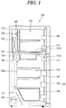
- FIG. 1 is a longitudinal sectional view schematically showing a configuration of a refrigerator 100 according to an embodiment of the present invention.
- the refrigerator 100 is an apparatus for storing food items stored therein at a low temperature, by using cold air generated by a refrigerating cycle where processes of compression-condensation-expansion-evaporation are consecutively performed.
- a refrigerator body 110 is provided therein with a storage space for storing food items.
- the storage space may be partitioned by a partition wall 111, and may be divided into a refrigerating chamber 112 and a freezing chamber 113 according to a setting temperature.
- a 'top mount type refrigerator' where the freezing chamber 113 is provided above the refrigerating chamber 112.
- the present invention is not limited to this. That is, the present invention may be also applied to a 'side by side type refrigerator' where a refrigerating chamber and a freezing chamber are arranged right and left, or a 'bottom freezer type refrigerator' where a refrigerating chamber is provided at an upper side and a freezing chamber is provided at a lower side, may be
- a door is connected to the refrigerator body 110 to open and close a front opening of the refrigerator body 110.
- a refrigerating chamber door 114 and a freezing chamber door 115 are configured to open and close front surfaces of the refrigerating chamber 112 and the freezing chamber 113, respectively.
- the door may be variously implemented as a rotation type door rotatably connected to the refrigerator body 110, a drawer type door slidably connected to the refrigerator body 110, etc.
- At least one accommodation unit 180 (e.g., a shelf 181, a tray 182, a basket 183, etc.) for efficient utilization of the storage space inside the refrigerator body 110 is provided at the refrigerator body 110.
- the shelf 181 and the tray 182 may be installed in the refrigerator body 110
- the basket 183 may be installed in the door 114 connected to the refrigerator body 110.
- a cooling chamber 116 having an evaporator 130 and a blower 140 is provided at a rear side of the freezing chamber 113.
- a mechanical chamber 117 is provided at a lower side of a rear surface of the refrigerator body 110, and a compressor 160, a condenser (not shown), etc. are provided in the mechanical chamber 117.
- Air inside the refrigerating chamber 112 and the freezing chamber 113 is sucked into the cooling chamber 116 through the refrigerating chamber feedback duct 111a and the freezing chamber feedback duct 111b of the partition wall 111, by the blower 140 of the cooling chamber 116, thereby being heat-exchanged with the evaporator 130. Then, the air is discharged to the refrigerating chamber 112 and the freezing chamber 113 through the cold air discharge openings 150a of the cold air duct 150. These processes are repeatedly performed.
- frost is generated on the surface of the evaporator 130 due to a temperature difference from circulation air re-introduced through the refrigerating chamber feedback duct 111a and the freezing chamber feedback duct 111b.
- a defroster 170 is provided at the evaporator 130, and water removed by the defroster 170 (i.e., defrosting water) is collected at a defrosting water container (not shown) formed at a lower side of the refrigerator body 110, through a defrosting water discharge pipe 118.
- defroster 170 capable of reducing a power consumption at the time of defrosting, and capable of enhancing a heat exchange rate.
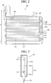
- FIG. 2 is a view conceptually showing a first embodiment of the defroster 170 applied to the refrigerator of FIG. 1
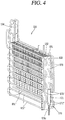
- FIG. 3 is a sectional view of a heating unit 171 shown in FIG. 2 .
- the evaporator 130 includes a cooling pipe 131, a plurality of cooling fins 132, and a plurality of supporting plates 133.
- a part of the cooling fins 132 was omitted.
- a detailed configuration of the evaporator 130 is shown in FIG. 4 .
- the cooling pipe 131 forms a plurality of rows by being repeatedly bent in a zigzag manner, and has therein a refrigerant.
- the cooling pipe 131 may be configured by a combination of a horizontal pipe portion and a bent pipe portion.
- the horizontal pipe portions are disposed to be parallel to each other up and down, and are configured to penetrate the cooling fins 132.
- the bent pipe portion is configured to connect an end part of the upper horizontal pipe portion with an end part of the lower horizontal pipe portion, for internal communication with each other.
- the cooling pipe 131 may be formed to have a single line, or may be formed to have a plurality of lines in back and forth directions of the evaporator 130.
- the plurality of supporting plates 133 are provided at both sides of the evaporator 130, and each of the supporting plates 133 is vertically extended in an up-down direction to support bent end parts of the cooling pipe 131.
- An insertion groove for fitting a heat pipe 172 to be explained later thereinto is formed at each of the supporting plates 133.
- the defroster 170 is configured to remove frost generated from the evaporator 130, and is installed at the evaporator 130 as shown.
- the defroster 170 includes a heating unit 171 and a heat pipe 172.
- the heating unit 171 is electrically connected to a controller (not shown), and is formed to generate heat at the time of receiving an operation signal from the controller.
- the controller may be configured to apply an operation signal to the heating unit 171 at each preset time interval, or to apply an operation signal to the heating unit 171 when a sensed temperature of the cooling chamber 116 is lower than a preset temperature.
- the heating unit 171 includes a heater case 171a and a heater 171b.
- the heater case 171a is extended in one direction, and is vertically disposed outside the evaporator 130 in an up-down direction.
- the heater case 171a may be disposed outside one supporting plate 133 in parallel to the supporting plate 133 with a predetermined interval.
- the heater case 171a may be arranged at one side of the evaporator 130 where an accumulator 134 is positioned, or may be arranged at another side, the opposite side.
- the heater case 171a may be formed to have a cylindrical shape or a square pillar shape.
- an outlet 171' communicated with one end of the heat pipe 172 is formed at an upper side of the heater case 171a (e.g., an upper surface of the heater case 171a or an outer circumferential surface adjacent to the upper surface).
- the outlet 171' means an opening through which the evaporated working fluid (F) is discharged to the heat pipe 172.
- An inlet 171" communicated with a return part 172b is formed at a lower side of the heater case 171a (e.g., a bottom surface of the heater case 171a or an outer circumferential surface adjacent to the bottom surface).
- the inlet 171" means an opening through which the working fluid (F) condensed while passing through the heat pipe 172 is collected to the heating unit 171.
- the heater 171b is accommodated in the heater case 171a, and has an extended shape in a lengthwise direction of the heater case 171a. That is, the heater 171b is vertically arranged in an up-down direction of the evaporator 130.
- the heater 171b may be inserted through a bottom surface of the heater case 171a, thereby being fixed to the heater case 171a. That is, a lower end of the heater 171b may be sealed and fixed to a bottom part of the heater case 171a, and an upper end of the heater 171b may be extended toward an upper part of the heater case 171a.
- the heater 171b is spaced apart from an inner circumferential surface of the heater case 171a with a preset interval. Under this arrangement, a ring-shaped space having a ring-shaped gap is formed between an inner circumferential surface of the heater case 171a and an outer circumferential surface of the heater 171b.
- a power source portion 171c is connected to the heater 171b so as to supply power to a coil (not shown) provided in the heater 171b.
- a part of the heater 171b where the coil is formed constitutes an active heating portion for evaporating a working fluid by being heated to a high temperature. The active heating portion will be explained later.
- the heat pipe 172 is connected to each of an outlet 171' provided at an upper side of the heating unit 171 and an inlet 171" provided at a lower side of the heating unit 171, and has therein a predetermined working fluid (F).
- a general refrigerant e.g., R-134a, R-600a, etc.
- R-134a e.g., R-134a, R-600a, etc.
- At least part of the heat pipe 172 is arranged near the cooling pipe 131 of the evaporator 130, such that the working fluid (F) heated by the heating unit 171 transfers heat to the evaporator 130 while passing through the heat pipe 172, for removal of frost.
- the working fluid (F) filled in the heat pipe 172 is heated to a high temperature by the heating unit 171
- the working fluid (F) flows by a pressure difference to move along the heat pipe 172.
- the high-temperature working fluid (F) heated by the heater 171b and discharged to the outlet 171' transfers heat to the cooling pipe 131 of the evaporator 130, while moving along the heat pipe 172.
- the working fluid (F) is cooled through such a heat exchange process, and is introduced into the inlet 171".
- the cooled working fluid (F) is re-heated by the heater 171b and then is discharged to the outlet 171', thereby repeatedly performing the above processes.
- the cooling pipe 131 is defrosted.
- the heat pipe 172 may have a repeatedly bent form (a zigzag form) like the cooling pipe 131.
- the heat pipe 172 may include a vertical extended portion 172a, a heat emitting portion 172b, and a return portion 172c.
- the vertical extended portion 172a is connected to the outlet 171' of the heating unit 171, and is vertically arranged in an up-down direction of the evaporator 130.
- the vertical extended portion 172a is extended up to an upper part of the evaporator 130, in an arranged state outside one supporting plate 133 in parallel to the supporting plate 133 with a predetermined interval.
- the heat emitting portion 172b is extended in a zigzag form along the cooling pipe 131 of the evaporator 130.
- the heat emitting portion 172b may be implemented by a combination of a plurality of horizontal pipes which form rows, and a connection pipe bent in a U-shape so as to connect the plurality of horizontal pipes to each other in a zigzag form.
- the heat emitting portion 172b may be extended up to a position adjacent to the accumulator 134, in order to remove frost on the accumulator 134. As shown, the heat emitting portion 172b may be upward extended towards the accumulator 134, and then may be downward bent and extended towards the cooling pipe 131.
- the heater 171b is accommodated in the heater case 171a, and is extended in a lengthwise direction of the heater case 171a. And a predetermined working fluid (F) is filled in the heating unit 171 and the heat pipe 172.
- the heater 171b When all of the working fluid (F) is in a liquid state (when the heater 171b is not operated), if an upper end of the heater 171b is exposed above a surface of the working fluid (F), the heater 171b may be operated. In this case, the upper end of the heater 171b may have its temperature increased drastically, unlike the remaining parts immersed in the working fluid (F).
- the upper end of the heater 171b may be overheated to cause a lethal damage (e.g., fire) to the defroster 170. Further, the heated working fluid (F) may backflow to the return portion of the heat pipe 172.
- a lethal damage e.g., fire
- the working fluid (F) is filled in the heater case 171a so as to form the surface at a position higher than the upper end of the heater 171b, in a liquid state (when the heater 171b is not operated). That is, the heater 171b is configured to be immersed below the surface of the working fluid (F).
- the active heating portion 171b' is configured to emit heat actively.
- the working fluid (F) in a liquid state may be heated by the active heating portion 171b' to thus have a phase change into a high-temperature gaseous state.
- the passive heating portion 171b" is provided below the active heating portion 171b'.
- the passive heating portion 171b” cannot emit heat spontaneously, and is heated to a low temperature by receiving heat from the active heating portion 171b'.
- the passive heating portion 171b” causes the working fluid (F) which is in a liquid state to have a temperature increase a little. But the passive heating portion 171b" does not have a high temperature high enough to make the working fluid (F) have a phase change into a gaseous state.
- the inlet 171" of the heating unit 171 is positioned to correspond to the passive heating portion 171b", such that the working fluid (F) which returns after moving along the heat pipe 172 is introduced into the passive heating portion 171b".
- FIG. 3 shows that the inlet 171" of the heating unit 171 is formed on an outer circumference of a part of the heater case 171a which encloses the passive heating portion 171b".
- the outlet 171' of the heating unit 171 is positioned to correspond to the active heating portion 171b', or is positioned above the active heating portion 171b'.
- FIG. 3 shows that the outlet 171' of the heating unit 171 is formed on an outer circumference of a part of the heater case 171a which encloses the active heating portion 171b'.
- the heat pipe 172 may be divided into an evaporation part (E) of a high temperature and a condensation part (C) of a low temperature, according to a state of the working fluid (F) which circulates.
- the evaporation part (E) is a part where the working fluid (F) moves in a high-temperature gas state or in a high-temperature gas/liquid state, which has a temperature where the cooling pipe 131 can be defrosted.
- the evaporation part (E) is connected to the outlet 171' of the heating unit 171, and is arranged to correspond to the cooling pipe 131 of the evaporator 130 to transfer heat to the cooling pipe 131 of the evaporator 130.
- the condensation part (C) is a part where the working fluid (F) moves in a low-temperature liquid state, which has a lower temperature than a temperature where the cooling pipe 131 can be defrosted.
- the condensation part (C) is arranged near the cooling pipe 131, the cooling pipe 131 cannot be smoothly defrosted.
- the heat pipe 172 is extended in a zigzag form in a downward direction.
- the condensation part (C) is arranged near the cooling pipe 131. This means that the lower side cooling pipe 131 cannot be smoothly defrosted.
- the condensation part (C) is extended from the evaporation part (E), and is arranged below a lowermost-row cooling pipe 131' of the evaporator 130.
- the condensation part (C) includes at least two horizontal pipes 172' disposed below the lowermost-row cooling pipe 131' of the evaporator 130.
- FIG. 2 shows a structure that the heat pipe 172 constitutes the condensation part (C) by further including two rows below the lowermost-row cooling pipe 131' of the evaporator 130.
- a lower end of the heating unit 171 is arranged near the lowermost-row cooling pipe 131'. Accordingly, the return part is upward extended in a bent shape, from the lowermost-row horizontal pipe of the condensation part (C) to the inlet 171" of the heating unit 171. That is, the return part is communicated with each of the lowermost-row horizontal pipe of the condensation part (C) and the inlet 171" of the heating unit 171, thereby forming a flow path along which the condensed working fluid (F) can be collected.
- the return part of a bent shape has a large flow resistance, which is advantageous in preventing a backflow of the working fluid (F) which returns to the inlet 171" of the heating unit 171.
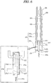
- FIG. 4 is a view showing a detailed embodiment of the defroster 170 shown in FIG. 2 .
- a cooling pipe 131 forms a plurality of rows by being repeatedly bent in a zigzag form.
- the cooling pipe 131 may be formed as a copper pipe, and has therein a refrigerant.
- a heat pipe 172 forms a plurality of rows by being repeatedly bent in a zigzag form.
- the heat pipe 172 may be formed as a copper pipe, and a working fluid (F) is filled in the heat pipe 172.
- the heat pipe 172 includes a first heat pipe and a second heat pipe, and the first and second heat pipes are arranged outside the first and second cooling pipes, respectively.
- the heat pipe 172 may be configured to implement a single line.
- the heat pipe 172 may be configured to be accommodated between the cooling fins 132 fixed to each row of the cooling pipe 131. Under such a structure, the heat pipe 172 is arranged between the respective rows of the cooling pipe 131. In this case, the heat pipe 172 may be configured to contact the cooling fins 132.
- the heat pipe 172 may be installed to penetrate the plurality of cooling fins 132. That is, the heat pipe 172 may be expanded when inserted into the insertion holes of the cooling fins 132, thereby being firmly fitted into the insertion holes. Under such a structure, heat may be transferred to the cooling pipe 131 through the cooling fins 132. This is advantageous in the aspect of heat transfer efficiency.
- a heating unit 171 is vertically arranged outside one supporting plate 133 in an up-down direction of the evaporator 130, in a spaced manner from the one supporting plate 133 with a predetermined gap. As shown, a part of the heating unit 171 may be accommodated between first and second cooling pipes 131 which are protruded from the one supporting plate 133 and bent.
- the heating unit 171 includes a heater case 171a connected to both ends of the heat pipe 172 and forming a closed loop where the working fluid (F) can circulate, and a heater 171b configured to heat the working fluid (F).
- the heat case 171a includes first and second outlets 171' for discharging the heated working fluid (F) to the first and second heat pipes, and first and second inlets 171" for introducing the cooled working fluid (F) from the first and second heat pipes.
- the first and second outlets 171' are formed on an outer circumferential surface of an upper side of the heater case 171a, and are connected to one ends of the first and second heat pipes, respectively.
- the first and second inlets 171" are formed on an outer circumferential surface of a lower side of the heater case 171a, and are connected to another ends of the first and second heat pipes, respectively.
- the heater 171b includes an active heating portion 171b' configured to emit heat actively, and a passive heating portion 171b" provided below the active heating portion 171b'. And the active heating portion 171b' and the passive heating portion 171b" are accommodated in the heater case 171a, and are extended in a lengthwise direction of the heater case 171a. That is, in the heater case 171a, the active heating portion 171b' is positioned at an upper side, and the passive heating portion 171b" is positioned at a lower side.
- a height of the surface of the working fluid (F) filled in the heating unit 171 is higher than a height of an uppermost end of the active heating portion 171b'. This configuration is to prevent the active heating portion 171b' from being overheated.
- the first and second outlets 171' of the heater case 171a are formed on an outer circumferential surface of the heater case 171a which encloses the active heating portion 171b', and the first and second inlets 171" of the heater case 171a are formed on an outer circumferential surface of the heater case 171a which encloses the passive heating portion 171b".
- the cooled working fluid (F) introduced through the first and second inlets 171" is introduced into the passive heating portion 171b". Then, the working fluid (F) is re-heated by the active heating portion 171b", and is discharged out through the first and second outlets 171'.
- the heat pipe 172 connected to the first and second outlets 171'of the heater case 171a is vertically extended towards an upper side of the evaporator 130, and then is extended to a lower side of the evaporator 130 by being repeatedly bent in a zigzag form in correspondence to the cooling pipe 131 of the evaporator 130.
- the heat pipe 172 before the working fluid (F) is introduced into the first and second inlets 171" of the heater case 171a may have a predetermined temperature lower than a temperature where defrosting can be performed.
- the heat pipe 172 is configured to further include at least two horizontal pipes 172' disposed below a lowermost-row cooling pipe 131' of the evaporator 130, such that only the heat pipe 172 of a high temperature is used to defrost the evaporator 130.
- illustrated is a structure that the heat pipe 172 is formed by further including two rows below the lowermost-row cooling pipe 131' of the evaporator 130.
- the supporting plates 133 provided at both sides of the evaporator 130 may be extended to a position below the lowermost-row cooling pipe 131', thereby fixing and supporting the at least two horizontal pipes 172' disposed below the lowermost-row cooling pipe 131' of the evaporator 130.
- a heating unit 271 includes a heater case 271a vertically arranged outside an evaporator 230 in an up-down direction, and a heater 271b extended in the heater case 271a in a lengthwise direction of the heater case 271a. That is, the heater 271b is vertically arranged in an up-down direction of the evaporator 230.
- An outlet 271' for discharging the working fluid (F) heated by the heater 271b is formed at an upper side of the heater case 271a.
- the heater 271b is categorized into an active heating portion 271b' and a passive heating portion 271b" according to whether it emits heat actively or passively.
- the active heating portion 271b' is heated to a high temperature to evaporate the working fluid (F).
- the passive heating portion 271b" provided below the active heating portion 271b' is heated to a low temperature by receiving heat from the active heating portion 271b'.
- the passive heating portion 271b" does not have a high temperature high enough to evaporate the working fluid (F).
- the heater 271b corresponding to the inlet 271" for introducing the working fluid (F) is formed as the passive heating portion 271b", and the active heating portion 271b' is upward extended from the passive heating portion 271b". That is, since the working fluid (F) which returns to the inlet 271" of the heating unit 271 is introduced to the active heating portion 271b' via the passive heating portion 271b", the working fluid (F) is not immediately re-heated. This may prevent a backflow of the working fluid (F).
- the heat pipe 272 is connected to each of the outlet 271' and the inlet 271" of the heater case 271a. And at least part of the heat pipe 272 is arranged near the cooling pipe 231 of the evaporator 230, such that the working fluid (F) is heat-exchanged with the cooling pipe 231 of the evaporator 230.
- the high-temperature working fluid (F) of a gaseous state, heated by the active heating portion 271b' is transferred to the heat pipe 272 through the outlet 271'.
- the working fluid (F) undergoes a phase change through a heat exchange while flowing along the heat pipe 272, thereby being cooled to a liquid state.
- the working fluid (F) is collected to the passive heating portion 271b" through the inlet 271", and then is re-heated by the active heating portion 271b' to thus be supplied. That is, the working fluid (F) is implemented to form a circulation loop.
- the heat pipe 272 includes at least two horizontal pipes 272' disposed below a lowermost-row cooling pipe 231' of the evaporator 230.
- FIG. 5 shows that a part of the heat pipe 272 is further provided with two rows below the lowermost-row cooling pipe 231' of the evaporator 230.
- a part of the heating unit 271 is arranged below the lowermost-row cooling pipe 231' of the evaporator 230.
- a lower end of the heating unit 271 may be positioned near a lowermost-row horizontal pipe of the heat pipe 272.
- an upper end of the heating unit 271 may be positioned below a cooling pipe 231" formed directly above the lowermost-row cooling pipe 231' of the evaporator 230 (i.e., the second cooling pipe from the lower side).
- a return part 272c for connecting the lowermost-row horizontal pipe of the heat pipe 272 with the inlet 271" of the heating unit 271 is formed to have a shorter length than the return part in the first embodiment.
- the return part 272c may be extended from the lowermost-row horizontal pipe of the heat pipe 272 in a bent manner in a horizontal direction, and may be connected to the inlet 271" of the heating unit 271.
- the lowermost-row horizontal pipe of the heat pipe 272 may be directly connected to the inlet 271" of the heating unit 271 without the return part.
- the heating unit 271 since the heating unit 271 is arranged near the lowermost-row horizontal pipe of the heat pipe 272, the heater 271b may be immersed below the surface of the smaller amount of working fluid (F) than the working fluid (F) in the first embodiment. Further, as the amount of the working fluid (F) is reduced, a temperature of the lowermost-row horizontal pipe of the heat pipe 272 may be increased to a value where defrosting can be performed. That is, the heat pipe 272 may entirely have a value more than a temperature where defrosting can be performed.
- the working fluid (F) was filled by 30 ⁇ 40% with respect to a volume of the heat pipe 272. Accordingly, it was checked that the heat pipe 272 had entirely a value more than a temperature where defrosting can be performed, and a partial overheating of the heater 271b was prevented.
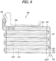
- FIG. 8 is a view conceptually showing a third embodiment of a defroster 370 applied to the refrigerator of FIG. 1 .
- FIG. 9 is a sectional view of a heating unit 371 shown in FIG. 8 .
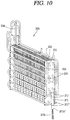
- FIG. 10 is a view showing a detailed embodiment of the defroster 370 shown in FIG. 8 .
- the heating unit 371 includes a heater case 371a connected to both ends of the heat pipe 372 and forming a closed loop where a working fluid (F) can circulate, and a heater 371b configured to heat the working fluid (F).
- the heater 371b includes an active heating portion 371b' configured to emit heat actively so as to heat the working fluid (F), and a passive heating portion 371b" provided below the active heating portion 371b' and heated to a lower temperature than the active heating portion 371b'.
- the heater case 371a is extended in one direction, and is arranged outside one supporting plate 333 in an up-down direction of an evaporator 330.
- An outlet 371' for discharging the working fluid (F) heated by the heater 371b is formed at an upper side of the heater case 371a.
- an inlet 371" for introducing the working fluid (F) cooled through a heat exchange with a cooling pipe 331 of the evaporator 330, is formed at a lower side of the heater case 371a.
- the heat pipe 372 is connected to each of the outlet 371' and the inlet 371" of the heater case 371a. And at least part of the heat pipe 372 is arranged near the cooling pipe 331 of the evaporator 330, such that the working fluid (F) is heat-exchanged with the cooling pipe 331 of the evaporator 330.
- the outlet 371' and the inlet 371" are arranged up and down, which corresponds to well a characteristic that the heated working fluid (F) moves upward.
- the structure where the heating unit 371 is arranged in an up-down direction of the evaporator 330 may significantly prevent a backflow of the heated working fluid (F) to the inlet 371".
- at least part of the passive heating portion 371b" of the heater 371b may be exposed to outside of the heater case 371a.
- the heater 371b inside the heater case 371a may be formed only as the active heating portion 371b', and the passive heating portion 371b" may be exposed to outside of the heater case 371a.
- the active heating portion 371b' is configured to be immersed below the surface of the working fluid (F).
- the passive heating portion 371b" exposed to outside of the heater case 371a is configured to lower a surface load of the heater 371b by emitting heat of the heater 371b to outside. If the surface load of the heater 371b is lowered, the heater 371b may have reliability by preventing its overheating, and a lifespan of the heater 371b may be prolonged.
- the heater case 371a since the heater 371b accommodated in the heater case 371a has a short length, the heater case 371a may have a reduced length.
- the heater 371b may be immersed below the surface of the smaller amount of working fluid (F) than the working fluid (F) in the second embodiment. Further, as the amount of the working fluid (F) is reduced, a temperature of the lowermost-row horizontal pipe of the heat pipe 372 may be increased to a value where defrosting can be performed. That is, the heat pipe 372 may entirely have a value more than a temperature where defrosting can be performed.
- the lowermost-row horizontal pipe of the heat pipe 372 has a temperature where defrosting can be performed.
- it is not required to install the heat pipe 372 below the lowermost-row cooling pipe 331' of the evaporator 330 by at least two rows.
- an upper end of the heating unit 371 may be positioned below a cooling pipe 331" formed directly above the lowermost-row cooling pipe 331' of the evaporator 330 (i.e., the second cooling pipe from the lower side).
- the inlet 371" of the heating unit 371 may be positioned to correspond to a lower part of the active heating portion 371b'.
- the outlet 371' of the heating unit 371, disposed above the inlet 371" may be positioned to correspond to an upper part of the active heating portion 371b', or may be positioned above the active heating portion 371b'.
Landscapes
- Engineering & Computer Science (AREA)
- Physics & Mathematics (AREA)
- Mechanical Engineering (AREA)
- Thermal Sciences (AREA)
- General Engineering & Computer Science (AREA)
- Chemical & Material Sciences (AREA)
- Combustion & Propulsion (AREA)
- Life Sciences & Earth Sciences (AREA)
- Sustainable Development (AREA)
- Geometry (AREA)
- Defrosting Systems (AREA)
Claims (15)
- Dégivreur, comprenant :un fluide de travail (F),une unité de chauffage (171, 271, 371) comprenant un carter (171a, 271a, 371a) d'élément chauffant disposé verticalement dans la direction de haut en bas d'un évaporateur (130, 230, 330) à l'extérieur dudit évaporateur (130, 230, 330), et comprenant un élément chauffant (171b, 271b, 371b) disposé verticalement dans le carter (171a, 271a, 371a) d'élément chauffant au moins partiellement dans la direction de haut en bas ; etun tuyau de chauffage (172, 272, 372) relié à une sortie (171', 271', 371') prévue en haut de l'unité de chauffage (171, 271, 371) ainsi qu'à une entrée (171", 271", 371") prévue en bas de l'unité de chauffage (171, 271, 371), et disposé au moins partiellement à proximité d'un tuyau de refroidissement (131, 231, 331) de l'évaporateur (130, 230, 330) de sorte que le fluide de travail (F) chauffé par l'élément chauffant (171b, 271b, 371b) transfère de la chaleur vers l'évaporateur (130, 230, 330) pour éliminer le givre en circulant,caractérisé en ce quelorsque la totalité du fluide de travail (F) à l'intérieur du tuyau de chauffage (172, 272, 372) est à l'état liquide, l'élément chauffant (171b, 271b, 371b) est prévu pour être placé sous une surface du fluide de travail (F), etle fluide de travail (F) est versé à l'état liquide dans le carter (171a, 271a, 371a) d'élément chauffant pour former une surface à un emplacement situé au-dessus d'une extrémité supérieure de l'élément chauffant (171b, 271b, 371b), de manière à immerger l'élément chauffant (171b, 271b, 371b) sous la surface du fluide de travail (F).
- Dégivreur selon la revendication 1, où l'élément chauffant (171b) comprend :une section de chauffage actif (171b') prévue pour diffuser une chaleur active de manière à chauffer le fluide de travail (F) ; etune section de chauffage passif (171b") prévue sous la section de chauffage actif (171b') et chauffée à une température inférieure à la section de chauffage actif (171b'),où l'entrée (171") de l'unité de chauffage (171) est placée de manière à correspondre à la section de chauffage passif (171b"), de sorte que le fluide de travail (F) revenant après circulation dans le tuyau de chauffage (172) pénètre dans la section de chauffage passif (171b").
- Dégivreur selon la revendication 2, où la sortie (171') de l'unité de chauffage (171) est placée de manière à correspondre à la section de chauffage actif (171b'), ou est placée au-dessus de la section de chauffage actif (171b').
- Dégivreur selon la revendication 1, où le tuyau de chauffage (172) comprend :
une section d'évaporation (E) reliée à la sortie (171') de l'unité de chauffage (171), et disposée de manière à correspondre au tuyau de refroidissement (131) de l'évaporateur (130) pour transférer de la chaleur vers le tuyau de refroidissement de l'évaporateur ; et une section de condensation (C) s'étendant de la section d'évaporation (E), disposée sous la rangée la plus basse du tuyau de refroidissement (131') de l'évaporateur (130), et reliée à l'entrée (171") de l'unité de chauffage (171). - Dégivreur selon la revendication 4, où la section de condensation (C) comprend au moins deux tuyaux horizontaux (172') prévus pour être disposés sous la rangée la plus basse du tuyau de refroidissement (131') de l'évaporateur (130).
- Dégivreur selon la revendication 5, où une extrémité inférieure de l'unité de chauffage (171) est prévue pour être disposée à proximité de la rangée la plus basse du tuyau de refroidissement (131') de l'évaporateur (130).
- Dégivreur selon la revendication 6, où la section de condensation (C) comprend une section de retour (172c) s'étendant vers le haut, de la rangée horizontale de tuyau la plus basse de la section de condensation (C) à l'entrée (171") de l'unité de chauffage (171).
- Dégivreur selon la revendication 5, où le bas de l'unité de chauffage (271) est prévu pour être disposé sous la rangée la plus basse du tuyau de refroidissement (231') de l'évaporateur (230).
- Dégivreur selon la revendication 8, où une extrémité inférieure de l'unité de chauffage (271) est disposée à proximité de la rangée horizontale de tuyau la plus basse (272') de la section de condensation (C).
- Dégivreur selon la revendication 9, où une extrémité supérieure de l'unité de chauffage (271) est prévue pour être placée sous un tuyau de refroidissement formé immédiatement au-dessus de la rangée la plus basse du tuyau de refroidissement (231') de l'évaporateur (230).
- Dégivreur selon la revendication 1, où la rangée horizontale de tuyau la plus basse du tuyau de chauffage (372) est prévue pour être disposée à proximité de la rangée la plus basse du tuyau de refroidissement (331') de l'évaporateur (330), et
où une extrémité supérieure de l'unité de chauffage (371) est prévue pour être placée sous un tuyau de refroidissement formé immédiatement au-dessus de la rangée la plus basse du tuyau de refroidissement (331') de l'évaporateur (330). - Dégivreur selon la revendication 11, où l'élément chauffant (371b) comprend une section de chauffage actif (371b') prévue pour diffuser une chaleur active de manière à chauffer le fluide de travail (F), et
où l'entrée (371 ") de l'unité de chauffage est placée de manière à correspondre à la section de chauffage actif (371b'). - Dégivreur selon la revendication 12, où l'élément chauffant (371b) comprend en outre une section de chauffage passif (371b") prévue sous la section de chauffage actif (371b') et chauffée à une température inférieure à la section de chauffage actif (371b'), et
où au moins une partie de la section de chauffage passif (371b") est disposée à l'extérieur du carter (371a) d'élément chauffant. - Réfrigérateur, comprenant :une carrosserie (110) de réfrigérateur ;un évaporateur (130) monté sur la carrosserie (110) de réfrigérateur, et prévu pour refroidir un fluide par privation de chaleur d'évaporation environnante ; etun dégivreur (170) selon l'une des revendications 1 à 13, prévu pour éliminer le givre sur l'évaporateur (130).
- Réfrigérateur selon la revendication 14, où l'évaporateur (130) comprend :un tuyau de refroidissement (131) formant une pluralité de rangées en étant plié en zigzag de manière répétée ;une pluralité d'ailettes de refroidissement (132) fixées au tuyau de refroidissement (131), et espacées l'une de l'autre d'un intervalle défini dans la direction d'extension du tuyau de refroidissement (131) ; etune pluralité de plaques de support (133) prévues pour supporter les deux extrémités de chaque rangée du tuyau de refroidissement (131).
Applications Claiming Priority (3)
| Application Number | Priority Date | Filing Date | Title |
|---|---|---|---|
| KR20140142753 | 2014-10-21 | ||
| KR1020150119083A KR102327894B1 (ko) | 2014-10-21 | 2015-08-24 | 제상 장치 및 이를 구비하는 냉장고 |
| PCT/KR2016/009365 WO2017034314A1 (fr) | 2014-10-21 | 2016-08-24 | Dégivreur et réfrigérateur le comportant |
Publications (3)
| Publication Number | Publication Date |
|---|---|
| EP3343135A1 EP3343135A1 (fr) | 2018-07-04 |
| EP3343135A4 EP3343135A4 (fr) | 2019-04-10 |
| EP3343135B1 true EP3343135B1 (fr) | 2020-09-30 |
Family
ID=55915809
Family Applications (2)
| Application Number | Title | Priority Date | Filing Date |
|---|---|---|---|
| EP16805958.2A Active EP3343134B1 (fr) | 2014-10-21 | 2016-08-01 | Agencement comprenant un dispositif de dégivrage et un évaporateur |
| EP16839603.4A Active EP3343135B1 (fr) | 2014-10-21 | 2016-08-24 | Dégivreur et réfrigérateur le comportant |
Family Applications Before (1)
| Application Number | Title | Priority Date | Filing Date |
|---|---|---|---|
| EP16805958.2A Active EP3343134B1 (fr) | 2014-10-21 | 2016-08-01 | Agencement comprenant un dispositif de dégivrage et un évaporateur |
Country Status (4)
| Country | Link |
|---|---|
| US (2) | US11226150B2 (fr) |
| EP (2) | EP3343134B1 (fr) |
| KR (3) | KR20160046713A (fr) |
| WO (2) | WO2017034170A1 (fr) |
Families Citing this family (16)
| Publication number | Priority date | Publication date | Assignee | Title |
|---|---|---|---|---|
| CN106662385B (zh) * | 2014-10-21 | 2019-05-03 | Lg 电子株式会社 | 除霜装置和具有该除霜装置的冰箱 |
| EP3367025B1 (fr) * | 2015-10-21 | 2020-03-11 | LG Electronics Inc. | Dispositif de dégivrage et réfrigérateur le comprenant |
| KR102491602B1 (ko) * | 2015-10-23 | 2023-01-25 | 삼성전자주식회사 | 공기조화기 |
| WO2017161425A1 (fr) * | 2016-03-24 | 2017-09-28 | Scantec Refrigeration Technologies Pty. Ltd. | Système de dégivrage |
| WO2017208760A1 (fr) * | 2016-06-01 | 2017-12-07 | 株式会社デンソー | Échangeur de chaleur régénératif |
| KR101987697B1 (ko) * | 2016-09-12 | 2019-06-11 | 엘지전자 주식회사 | 증발기 및 이를 구비하는 냉장고 |
| KR102182084B1 (ko) * | 2016-09-29 | 2020-11-23 | 엘지전자 주식회사 | 냉장고 |
| KR102312536B1 (ko) * | 2017-05-25 | 2021-10-14 | 엘지전자 주식회사 | 제상 장치 및 이를 구비하는 냉장고 |
| EP3633293A4 (fr) | 2017-05-25 | 2021-04-28 | LG Electronics Inc. | Appareil de dégivrage et réfrigérateur le comprenant |
| KR102511095B1 (ko) | 2017-12-13 | 2023-03-16 | 엘지전자 주식회사 | 진공단열체 및 냉장고 |
| KR102530909B1 (ko) * | 2017-12-13 | 2023-05-11 | 엘지전자 주식회사 | 진공단열체 및 냉장고 |
| KR102568737B1 (ko) | 2017-12-13 | 2023-08-21 | 엘지전자 주식회사 | 진공단열체 및 냉장고 |
| KR20210099719A (ko) | 2020-02-05 | 2021-08-13 | 삼성전자주식회사 | 냉장고 |
| US20210354080A1 (en) * | 2020-05-14 | 2021-11-18 | Water Global Solutions, S.L. | Air Humidity Condensing and Potabilizing Machine |
| US11828504B2 (en) * | 2020-09-21 | 2023-11-28 | Whirlpool Corporation | Heat exchanger for an appliance |
| KR102810701B1 (ko) * | 2021-12-29 | 2025-05-26 | 주식회사 경동나비엔 | 열교환기 |
Family Cites Families (26)
| Publication number | Priority date | Publication date | Assignee | Title |
|---|---|---|---|---|
| US1890085A (en) * | 1930-06-09 | 1932-12-06 | C V Hill & Co Inc | Defrosting device for refrigerating cases |
| US2081479A (en) * | 1932-04-18 | 1937-05-25 | Kelvinator Corp | Refrigerator defrosting method and apparatus |
| US2553657A (en) * | 1947-03-06 | 1951-05-22 | Francis L La Porte | Refrigerator defrosting method and apparatus |
| US2513823A (en) * | 1947-09-02 | 1950-07-04 | Tyler Fixture Corp | Refrigerator defrosting device |
| US2652697A (en) * | 1948-02-11 | 1953-09-22 | Louis C Pellegrini | Defrosting system for heat exchange devices |
| US2526032A (en) * | 1948-10-11 | 1950-10-17 | Francis L La Porte | Defrosting method and apparatus for refrigeration systems |
| US2631442A (en) * | 1951-05-22 | 1953-03-17 | Bally Case And Cooler Company | Automatic defrosting system and assembly |
| GB854771A (en) * | 1957-11-15 | 1960-11-23 | Gen Electric Co Ltd | Improvements in or relating to refrigerator evaporators and refrigerator evaporator arrangements |
| JPS589911B2 (ja) * | 1978-11-29 | 1983-02-23 | 株式会社日立製作所 | 冷凍機用蒸発器 |
| JPH05346284A (ja) | 1991-01-24 | 1993-12-27 | Mitsubishi Electric Corp | 冷却装置 |
| JPH07190597A (ja) * | 1993-12-24 | 1995-07-28 | Matsushita Refrig Co Ltd | 冷凍冷蔵庫の除霜装置 |
| JPH08303932A (ja) | 1995-05-08 | 1996-11-22 | Fuji Electric Co Ltd | 冷凍冷蔵ショーケースの除霜装置 |
| KR100512641B1 (ko) | 1999-11-19 | 2005-09-02 | 엘지전자 주식회사 | 대용량 냉장고의 제상시스템 |
| KR100388708B1 (ko) * | 2001-07-12 | 2003-06-25 | 삼성전자주식회사 | 제상히터를 갖춘 냉장고 |
| KR100469322B1 (ko) | 2002-02-19 | 2005-02-02 | 삼성전자주식회사 | 증발기 |
| JP3933613B2 (ja) * | 2002-08-06 | 2007-06-20 | 三星電子株式会社 | 冷蔵庫及び除霜装置 |
| KR100494389B1 (ko) * | 2002-08-06 | 2005-06-13 | 삼성전자주식회사 | 냉장고 및 제상장치 |
| JP4029092B2 (ja) * | 2004-10-26 | 2008-01-09 | 日本ピラー工業株式会社 | 流体用ヒータ及び流体加熱装置 |
| KR20080088807A (ko) * | 2007-03-30 | 2008-10-06 | 엘지전자 주식회사 | 냉장고의 제상장치 |
| KR101036685B1 (ko) | 2009-03-31 | 2011-05-23 | 공상운 | 버블젯을 이용한 루프형 히트파이프 |
| KR100962979B1 (ko) * | 2009-10-19 | 2010-06-10 | 박자현 | 히트 유닛 및 이를 이용한 난방 패널 |
| ES2833102T3 (es) * | 2010-02-23 | 2021-06-14 | Lg Electronics Inc | Refrigerador |
| KR101125827B1 (ko) * | 2010-05-03 | 2012-03-27 | 김종수 | 버블젯을 이용한 루프형 히트파이프가 적용된 제상모듈 |
| KR20130016999A (ko) | 2011-08-09 | 2013-02-19 | 박지오 | 튜브의 내부에 설치된 제상히터를 구비한 증발기 및 그 제조방법 |
| EP2938944A1 (fr) | 2012-12-31 | 2015-11-04 | Arçelik Anonim Sirketi | Dispositif de refroidissement comprenant un élément chauffant de dégivrage |
| WO2016064200A2 (fr) * | 2014-10-21 | 2016-04-28 | Lg Electronics Inc. | Dispositif de dégivrage et réfrigérateur le comprenant |
-
2015
- 2015-08-17 KR KR1020150115650A patent/KR20160046713A/ko active Pending
- 2015-08-24 KR KR1020150119087A patent/KR102295390B1/ko active Active
- 2015-08-24 KR KR1020150119083A patent/KR102327894B1/ko active Active
-
2016
- 2016-08-01 US US15/502,790 patent/US11226150B2/en active Active
- 2016-08-01 WO PCT/KR2016/008433 patent/WO2017034170A1/fr not_active Ceased
- 2016-08-01 EP EP16805958.2A patent/EP3343134B1/fr active Active
- 2016-08-24 US US15/747,866 patent/US10871320B2/en active Active
- 2016-08-24 EP EP16839603.4A patent/EP3343135B1/fr active Active
- 2016-08-24 WO PCT/KR2016/009365 patent/WO2017034314A1/fr not_active Ceased
Non-Patent Citations (1)
| Title |
|---|
| None * |
Also Published As
| Publication number | Publication date |
|---|---|
| EP3343134B1 (fr) | 2020-04-22 |
| EP3343135A4 (fr) | 2019-04-10 |
| US11226150B2 (en) | 2022-01-18 |
| WO2017034314A1 (fr) | 2017-03-02 |
| KR102295390B1 (ko) | 2021-08-31 |
| KR20160046715A (ko) | 2016-04-29 |
| US10871320B2 (en) | 2020-12-22 |
| EP3343134A4 (fr) | 2019-04-10 |
| KR20160046714A (ko) | 2016-04-29 |
| KR20160046713A (ko) | 2016-04-29 |
| EP3343135A1 (fr) | 2018-07-04 |
| KR102327894B1 (ko) | 2021-11-18 |
| WO2017034170A1 (fr) | 2017-03-02 |
| EP3343134A1 (fr) | 2018-07-04 |
| US20190011171A1 (en) | 2019-01-10 |
| US20180156523A1 (en) | 2018-06-07 |
Similar Documents
| Publication | Publication Date | Title |
|---|---|---|
| EP3343135B1 (fr) | Dégivreur et réfrigérateur le comportant | |
| US11079148B2 (en) | Defrosting device and refrigerator having the same | |
| CN107166866B (zh) | 冰箱以及冰箱的控制方法 | |
| US5941085A (en) | Refrigerator having an apparatus for defrosting | |
| US10408525B2 (en) | Defrosting device and refrigerator having the same | |
| EP3109572A1 (fr) | Réfrigérateur | |
| JP6484709B2 (ja) | 除霜装置及びそれを備える冷蔵庫 | |
| EP3586074B1 (fr) | Réfrigérateur | |
| KR20210099719A (ko) | 냉장고 | |
| KR20170032878A (ko) | 제상 장치 및 이를 구비하는 냉장고 | |
| KR20170032879A (ko) | 제상 장치 및 이를 구비하는 냉장고 | |
| KR20190104776A (ko) | 제상 장치 및 이를 구비하는 냉장고 |
Legal Events
| Date | Code | Title | Description |
|---|---|---|---|
| STAA | Information on the status of an ep patent application or granted ep patent |
Free format text: STATUS: THE INTERNATIONAL PUBLICATION HAS BEEN MADE |
|
| PUAI | Public reference made under article 153(3) epc to a published international application that has entered the european phase |
Free format text: ORIGINAL CODE: 0009012 |
|
| STAA | Information on the status of an ep patent application or granted ep patent |
Free format text: STATUS: REQUEST FOR EXAMINATION WAS MADE |
|
| 17P | Request for examination filed |
Effective date: 20180324 |
|
| AK | Designated contracting states |
Kind code of ref document: A1 Designated state(s): AL AT BE BG CH CY CZ DE DK EE ES FI FR GB GR HR HU IE IS IT LI LT LU LV MC MK MT NL NO PL PT RO RS SE SI SK SM TR |
|
| AX | Request for extension of the european patent |
Extension state: BA ME |
|
| DAV | Request for validation of the european patent (deleted) | ||
| DAX | Request for extension of the european patent (deleted) | ||
| A4 | Supplementary search report drawn up and despatched |
Effective date: 20190307 |
|
| RIC1 | Information provided on ipc code assigned before grant |
Ipc: F25B 47/02 20060101AFI20190301BHEP Ipc: F28D 21/00 20060101ALI20190301BHEP Ipc: F25D 21/08 20060101ALI20190301BHEP Ipc: F28F 1/32 20060101ALI20190301BHEP Ipc: F25D 21/00 20060101ALI20190301BHEP Ipc: F25B 39/02 20060101ALI20190301BHEP Ipc: F28D 1/047 20060101ALI20190301BHEP Ipc: F25D 19/00 20060101ALI20190301BHEP Ipc: F28D 15/02 20060101ALI20190301BHEP Ipc: F28F 1/28 20060101ALI20190301BHEP |
|
| GRAP | Despatch of communication of intention to grant a patent |
Free format text: ORIGINAL CODE: EPIDOSNIGR1 |
|
| STAA | Information on the status of an ep patent application or granted ep patent |
Free format text: STATUS: GRANT OF PATENT IS INTENDED |
|
| RIC1 | Information provided on ipc code assigned before grant |
Ipc: F28D 1/047 20060101ALI20200228BHEP Ipc: F25D 19/00 20060101ALI20200228BHEP Ipc: F25B 39/02 20060101ALI20200228BHEP Ipc: F25D 21/08 20060101ALI20200228BHEP Ipc: F28F 1/32 20060101ALI20200228BHEP Ipc: F28D 21/00 20060101ALI20200228BHEP Ipc: F25D 21/00 20060101ALI20200228BHEP Ipc: F25B 47/02 20060101AFI20200228BHEP Ipc: F28D 15/02 20060101ALI20200228BHEP |
|
| INTG | Intention to grant announced |
Effective date: 20200319 |
|
| GRAS | Grant fee paid |
Free format text: ORIGINAL CODE: EPIDOSNIGR3 |
|
| GRAA | (expected) grant |
Free format text: ORIGINAL CODE: 0009210 |
|
| STAA | Information on the status of an ep patent application or granted ep patent |
Free format text: STATUS: THE PATENT HAS BEEN GRANTED |
|
| AK | Designated contracting states |
Kind code of ref document: B1 Designated state(s): AL AT BE BG CH CY CZ DE DK EE ES FI FR GB GR HR HU IE IS IT LI LT LU LV MC MK MT NL NO PL PT RO RS SE SI SK SM TR |
|
| REG | Reference to a national code |
Ref country code: CH Ref legal event code: EP Ref country code: GB Ref legal event code: FG4D |
|
| REG | Reference to a national code |
Ref country code: AT Ref legal event code: REF Ref document number: 1319207 Country of ref document: AT Kind code of ref document: T Effective date: 20201015 |
|
| REG | Reference to a national code |
Ref country code: DE Ref legal event code: R096 Ref document number: 602016045139 Country of ref document: DE |
|
| REG | Reference to a national code |
Ref country code: IE Ref legal event code: FG4D |
|
| PG25 | Lapsed in a contracting state [announced via postgrant information from national office to epo] |
Ref country code: FI Free format text: LAPSE BECAUSE OF FAILURE TO SUBMIT A TRANSLATION OF THE DESCRIPTION OR TO PAY THE FEE WITHIN THE PRESCRIBED TIME-LIMIT Effective date: 20200930 Ref country code: NO Free format text: LAPSE BECAUSE OF FAILURE TO SUBMIT A TRANSLATION OF THE DESCRIPTION OR TO PAY THE FEE WITHIN THE PRESCRIBED TIME-LIMIT Effective date: 20201230 Ref country code: GR Free format text: LAPSE BECAUSE OF FAILURE TO SUBMIT A TRANSLATION OF THE DESCRIPTION OR TO PAY THE FEE WITHIN THE PRESCRIBED TIME-LIMIT Effective date: 20201231 Ref country code: SE Free format text: LAPSE BECAUSE OF FAILURE TO SUBMIT A TRANSLATION OF THE DESCRIPTION OR TO PAY THE FEE WITHIN THE PRESCRIBED TIME-LIMIT Effective date: 20200930 Ref country code: BG Free format text: LAPSE BECAUSE OF FAILURE TO SUBMIT A TRANSLATION OF THE DESCRIPTION OR TO PAY THE FEE WITHIN THE PRESCRIBED TIME-LIMIT Effective date: 20201230 Ref country code: HR Free format text: LAPSE BECAUSE OF FAILURE TO SUBMIT A TRANSLATION OF THE DESCRIPTION OR TO PAY THE FEE WITHIN THE PRESCRIBED TIME-LIMIT Effective date: 20200930 |
|
| REG | Reference to a national code |
Ref country code: AT Ref legal event code: MK05 Ref document number: 1319207 Country of ref document: AT Kind code of ref document: T Effective date: 20200930 |
|
| PG25 | Lapsed in a contracting state [announced via postgrant information from national office to epo] |
Ref country code: RS Free format text: LAPSE BECAUSE OF FAILURE TO SUBMIT A TRANSLATION OF THE DESCRIPTION OR TO PAY THE FEE WITHIN THE PRESCRIBED TIME-LIMIT Effective date: 20200930 Ref country code: LV Free format text: LAPSE BECAUSE OF FAILURE TO SUBMIT A TRANSLATION OF THE DESCRIPTION OR TO PAY THE FEE WITHIN THE PRESCRIBED TIME-LIMIT Effective date: 20200930 |
|
| REG | Reference to a national code |
Ref country code: NL Ref legal event code: MP Effective date: 20200930 |
|
| REG | Reference to a national code |
Ref country code: LT Ref legal event code: MG4D |
|
| PG25 | Lapsed in a contracting state [announced via postgrant information from national office to epo] |
Ref country code: CZ Free format text: LAPSE BECAUSE OF FAILURE TO SUBMIT A TRANSLATION OF THE DESCRIPTION OR TO PAY THE FEE WITHIN THE PRESCRIBED TIME-LIMIT Effective date: 20200930 Ref country code: PT Free format text: LAPSE BECAUSE OF FAILURE TO SUBMIT A TRANSLATION OF THE DESCRIPTION OR TO PAY THE FEE WITHIN THE PRESCRIBED TIME-LIMIT Effective date: 20210201 Ref country code: RO Free format text: LAPSE BECAUSE OF FAILURE TO SUBMIT A TRANSLATION OF THE DESCRIPTION OR TO PAY THE FEE WITHIN THE PRESCRIBED TIME-LIMIT Effective date: 20200930 Ref country code: LT Free format text: LAPSE BECAUSE OF FAILURE TO SUBMIT A TRANSLATION OF THE DESCRIPTION OR TO PAY THE FEE WITHIN THE PRESCRIBED TIME-LIMIT Effective date: 20200930 Ref country code: EE Free format text: LAPSE BECAUSE OF FAILURE TO SUBMIT A TRANSLATION OF THE DESCRIPTION OR TO PAY THE FEE WITHIN THE PRESCRIBED TIME-LIMIT Effective date: 20200930 Ref country code: SM Free format text: LAPSE BECAUSE OF FAILURE TO SUBMIT A TRANSLATION OF THE DESCRIPTION OR TO PAY THE FEE WITHIN THE PRESCRIBED TIME-LIMIT Effective date: 20200930 |
|
| PG25 | Lapsed in a contracting state [announced via postgrant information from national office to epo] |
Ref country code: AL Free format text: LAPSE BECAUSE OF FAILURE TO SUBMIT A TRANSLATION OF THE DESCRIPTION OR TO PAY THE FEE WITHIN THE PRESCRIBED TIME-LIMIT Effective date: 20200930 Ref country code: AT Free format text: LAPSE BECAUSE OF FAILURE TO SUBMIT A TRANSLATION OF THE DESCRIPTION OR TO PAY THE FEE WITHIN THE PRESCRIBED TIME-LIMIT Effective date: 20200930 Ref country code: ES Free format text: LAPSE BECAUSE OF FAILURE TO SUBMIT A TRANSLATION OF THE DESCRIPTION OR TO PAY THE FEE WITHIN THE PRESCRIBED TIME-LIMIT Effective date: 20200930 Ref country code: IS Free format text: LAPSE BECAUSE OF FAILURE TO SUBMIT A TRANSLATION OF THE DESCRIPTION OR TO PAY THE FEE WITHIN THE PRESCRIBED TIME-LIMIT Effective date: 20210130 Ref country code: PL Free format text: LAPSE BECAUSE OF FAILURE TO SUBMIT A TRANSLATION OF THE DESCRIPTION OR TO PAY THE FEE WITHIN THE PRESCRIBED TIME-LIMIT Effective date: 20200930 |
|
| PG25 | Lapsed in a contracting state [announced via postgrant information from national office to epo] |
Ref country code: SK Free format text: LAPSE BECAUSE OF FAILURE TO SUBMIT A TRANSLATION OF THE DESCRIPTION OR TO PAY THE FEE WITHIN THE PRESCRIBED TIME-LIMIT Effective date: 20200930 Ref country code: NL Free format text: LAPSE BECAUSE OF FAILURE TO SUBMIT A TRANSLATION OF THE DESCRIPTION OR TO PAY THE FEE WITHIN THE PRESCRIBED TIME-LIMIT Effective date: 20200930 |
|
| REG | Reference to a national code |
Ref country code: DE Ref legal event code: R097 Ref document number: 602016045139 Country of ref document: DE |
|
| PLBE | No opposition filed within time limit |
Free format text: ORIGINAL CODE: 0009261 |
|
| STAA | Information on the status of an ep patent application or granted ep patent |
Free format text: STATUS: NO OPPOSITION FILED WITHIN TIME LIMIT |
|
| PG25 | Lapsed in a contracting state [announced via postgrant information from national office to epo] |
Ref country code: DK Free format text: LAPSE BECAUSE OF FAILURE TO SUBMIT A TRANSLATION OF THE DESCRIPTION OR TO PAY THE FEE WITHIN THE PRESCRIBED TIME-LIMIT Effective date: 20200930 |
|
| 26N | No opposition filed |
Effective date: 20210701 |
|
| PG25 | Lapsed in a contracting state [announced via postgrant information from national office to epo] |
Ref country code: IT Free format text: LAPSE BECAUSE OF FAILURE TO SUBMIT A TRANSLATION OF THE DESCRIPTION OR TO PAY THE FEE WITHIN THE PRESCRIBED TIME-LIMIT Effective date: 20200930 |
|
| PG25 | Lapsed in a contracting state [announced via postgrant information from national office to epo] |
Ref country code: SI Free format text: LAPSE BECAUSE OF FAILURE TO SUBMIT A TRANSLATION OF THE DESCRIPTION OR TO PAY THE FEE WITHIN THE PRESCRIBED TIME-LIMIT Effective date: 20200930 |
|
| REG | Reference to a national code |
Ref country code: CH Ref legal event code: PL |
|
| PG25 | Lapsed in a contracting state [announced via postgrant information from national office to epo] |
Ref country code: MC Free format text: LAPSE BECAUSE OF FAILURE TO SUBMIT A TRANSLATION OF THE DESCRIPTION OR TO PAY THE FEE WITHIN THE PRESCRIBED TIME-LIMIT Effective date: 20200930 |
|
| REG | Reference to a national code |
Ref country code: BE Ref legal event code: MM Effective date: 20210831 |
|
| GBPC | Gb: european patent ceased through non-payment of renewal fee |
Effective date: 20210824 |
|
| PG25 | Lapsed in a contracting state [announced via postgrant information from national office to epo] |
Ref country code: LI Free format text: LAPSE BECAUSE OF NON-PAYMENT OF DUE FEES Effective date: 20210831 Ref country code: CH Free format text: LAPSE BECAUSE OF NON-PAYMENT OF DUE FEES Effective date: 20210831 |
|
| PG25 | Lapsed in a contracting state [announced via postgrant information from national office to epo] |
Ref country code: IS Free format text: LAPSE BECAUSE OF FAILURE TO SUBMIT A TRANSLATION OF THE DESCRIPTION OR TO PAY THE FEE WITHIN THE PRESCRIBED TIME-LIMIT Effective date: 20210130 Ref country code: LU Free format text: LAPSE BECAUSE OF NON-PAYMENT OF DUE FEES Effective date: 20210824 |
|
| PG25 | Lapsed in a contracting state [announced via postgrant information from national office to epo] |
Ref country code: IE Free format text: LAPSE BECAUSE OF NON-PAYMENT OF DUE FEES Effective date: 20210824 Ref country code: GB Free format text: LAPSE BECAUSE OF NON-PAYMENT OF DUE FEES Effective date: 20210824 Ref country code: FR Free format text: LAPSE BECAUSE OF NON-PAYMENT OF DUE FEES Effective date: 20210831 Ref country code: BE Free format text: LAPSE BECAUSE OF NON-PAYMENT OF DUE FEES Effective date: 20210831 |
|
| PG25 | Lapsed in a contracting state [announced via postgrant information from national office to epo] |
Ref country code: HU Free format text: LAPSE BECAUSE OF FAILURE TO SUBMIT A TRANSLATION OF THE DESCRIPTION OR TO PAY THE FEE WITHIN THE PRESCRIBED TIME-LIMIT; INVALID AB INITIO Effective date: 20160824 |
|
| PG25 | Lapsed in a contracting state [announced via postgrant information from national office to epo] |
Ref country code: CY Free format text: LAPSE BECAUSE OF FAILURE TO SUBMIT A TRANSLATION OF THE DESCRIPTION OR TO PAY THE FEE WITHIN THE PRESCRIBED TIME-LIMIT Effective date: 20200930 |
|
| PG25 | Lapsed in a contracting state [announced via postgrant information from national office to epo] |
Ref country code: MK Free format text: LAPSE BECAUSE OF FAILURE TO SUBMIT A TRANSLATION OF THE DESCRIPTION OR TO PAY THE FEE WITHIN THE PRESCRIBED TIME-LIMIT Effective date: 20200930 |
|
| PG25 | Lapsed in a contracting state [announced via postgrant information from national office to epo] |
Ref country code: MT Free format text: LAPSE BECAUSE OF FAILURE TO SUBMIT A TRANSLATION OF THE DESCRIPTION OR TO PAY THE FEE WITHIN THE PRESCRIBED TIME-LIMIT Effective date: 20200930 |
|
| PGFP | Annual fee paid to national office [announced via postgrant information from national office to epo] |
Ref country code: DE Payment date: 20250707 Year of fee payment: 10 |
|
| PG25 | Lapsed in a contracting state [announced via postgrant information from national office to epo] |
Ref country code: TR Free format text: LAPSE BECAUSE OF FAILURE TO SUBMIT A TRANSLATION OF THE DESCRIPTION OR TO PAY THE FEE WITHIN THE PRESCRIBED TIME-LIMIT Effective date: 20200930 |