EP3343152A1 - Einbaukühlschrank mit Kabeldeckeneinheit - Google Patents
Einbaukühlschrank mit Kabeldeckeneinheit Download PDFInfo
- Publication number
- EP3343152A1 EP3343152A1 EP17210033.1A EP17210033A EP3343152A1 EP 3343152 A1 EP3343152 A1 EP 3343152A1 EP 17210033 A EP17210033 A EP 17210033A EP 3343152 A1 EP3343152 A1 EP 3343152A1
- Authority
- EP
- European Patent Office
- Prior art keywords
- wire
- door
- built
- refrigerator
- case
- Prior art date
- Legal status (The legal status is an assumption and is not a legal conclusion. Google has not performed a legal analysis and makes no representation as to the accuracy of the status listed.)
- Granted
Links
Images


Classifications
-
- F—MECHANICAL ENGINEERING; LIGHTING; HEATING; WEAPONS; BLASTING
- F25—REFRIGERATION OR COOLING; COMBINED HEATING AND REFRIGERATION SYSTEMS; HEAT PUMP SYSTEMS; MANUFACTURE OR STORAGE OF ICE; LIQUEFACTION SOLIDIFICATION OF GASES
- F25D—REFRIGERATORS; COLD ROOMS; ICE-BOXES; COOLING OR FREEZING APPARATUS NOT OTHERWISE PROVIDED FOR
- F25D23/00—General constructional features
- F25D23/02—Doors; Covers
- F25D23/028—Details
-
- E—FIXED CONSTRUCTIONS
- E05—LOCKS; KEYS; WINDOW OR DOOR FITTINGS; SAFES
- E05D—HINGES OR SUSPENSION DEVICES FOR DOORS, WINDOWS OR WINGS
- E05D11/00—Additional features or accessories of hinges
- E05D11/0054—Covers, e.g. for protection
-
- E—FIXED CONSTRUCTIONS
- E05—LOCKS; KEYS; WINDOW OR DOOR FITTINGS; SAFES
- E05D—HINGES OR SUSPENSION DEVICES FOR DOORS, WINDOWS OR WINGS
- E05D11/00—Additional features or accessories of hinges
- E05D11/0081—Additional features or accessories of hinges for transmitting energy, e.g. electrical cable routing
-
- F—MECHANICAL ENGINEERING; LIGHTING; HEATING; WEAPONS; BLASTING
- F25—REFRIGERATION OR COOLING; COMBINED HEATING AND REFRIGERATION SYSTEMS; HEAT PUMP SYSTEMS; MANUFACTURE OR STORAGE OF ICE; LIQUEFACTION SOLIDIFICATION OF GASES
- F25D—REFRIGERATORS; COLD ROOMS; ICE-BOXES; COOLING OR FREEZING APPARATUS NOT OTHERWISE PROVIDED FOR
- F25D11/00—Self-contained movable devices, e.g. domestic refrigerators
-
- F—MECHANICAL ENGINEERING; LIGHTING; HEATING; WEAPONS; BLASTING
- F25—REFRIGERATION OR COOLING; COMBINED HEATING AND REFRIGERATION SYSTEMS; HEAT PUMP SYSTEMS; MANUFACTURE OR STORAGE OF ICE; LIQUEFACTION SOLIDIFICATION OF GASES
- F25D—REFRIGERATORS; COLD ROOMS; ICE-BOXES; COOLING OR FREEZING APPARATUS NOT OTHERWISE PROVIDED FOR
- F25D23/00—General constructional features
- F25D23/02—Doors; Covers
-
- E—FIXED CONSTRUCTIONS
- E05—LOCKS; KEYS; WINDOW OR DOOR FITTINGS; SAFES
- E05D—HINGES OR SUSPENSION DEVICES FOR DOORS, WINDOWS OR WINGS
- E05D3/00—Hinges with pins
- E05D3/06—Hinges with pins with two or more pins
- E05D3/16—Hinges with pins with two or more pins with seven parallel pins and four arms
-
- E—FIXED CONSTRUCTIONS
- E05—LOCKS; KEYS; WINDOW OR DOOR FITTINGS; SAFES
- E05Y—INDEXING SCHEME ASSOCIATED WITH SUBCLASSES E05D AND E05F, RELATING TO CONSTRUCTION ELEMENTS, ELECTRIC CONTROL, POWER SUPPLY, POWER SIGNAL OR TRANSMISSION, USER INTERFACES, MOUNTING OR COUPLING, DETAILS, ACCESSORIES, AUXILIARY OPERATIONS NOT OTHERWISE PROVIDED FOR, APPLICATION THEREOF
- E05Y2800/00—Details, accessories and auxiliary operations not otherwise provided for
- E05Y2800/10—Additional functions
- E05Y2800/122—Telescopic action
-
- E—FIXED CONSTRUCTIONS
- E05—LOCKS; KEYS; WINDOW OR DOOR FITTINGS; SAFES
- E05Y—INDEXING SCHEME ASSOCIATED WITH SUBCLASSES E05D AND E05F, RELATING TO CONSTRUCTION ELEMENTS, ELECTRIC CONTROL, POWER SUPPLY, POWER SIGNAL OR TRANSMISSION, USER INTERFACES, MOUNTING OR COUPLING, DETAILS, ACCESSORIES, AUXILIARY OPERATIONS NOT OTHERWISE PROVIDED FOR, APPLICATION THEREOF
- E05Y2800/00—Details, accessories and auxiliary operations not otherwise provided for
- E05Y2800/40—Physical or chemical protection
-
- E—FIXED CONSTRUCTIONS
- E05—LOCKS; KEYS; WINDOW OR DOOR FITTINGS; SAFES
- E05Y—INDEXING SCHEME ASSOCIATED WITH SUBCLASSES E05D AND E05F, RELATING TO CONSTRUCTION ELEMENTS, ELECTRIC CONTROL, POWER SUPPLY, POWER SIGNAL OR TRANSMISSION, USER INTERFACES, MOUNTING OR COUPLING, DETAILS, ACCESSORIES, AUXILIARY OPERATIONS NOT OTHERWISE PROVIDED FOR, APPLICATION THEREOF
- E05Y2900/00—Application of doors, windows, wings or fittings thereof
- E05Y2900/30—Application of doors, windows, wings or fittings thereof for domestic appliances
- E05Y2900/302—Application of doors, windows, wings or fittings thereof for domestic appliances for built-in appliances
-
- E—FIXED CONSTRUCTIONS
- E05—LOCKS; KEYS; WINDOW OR DOOR FITTINGS; SAFES
- E05Y—INDEXING SCHEME ASSOCIATED WITH SUBCLASSES E05D AND E05F, RELATING TO CONSTRUCTION ELEMENTS, ELECTRIC CONTROL, POWER SUPPLY, POWER SIGNAL OR TRANSMISSION, USER INTERFACES, MOUNTING OR COUPLING, DETAILS, ACCESSORIES, AUXILIARY OPERATIONS NOT OTHERWISE PROVIDED FOR, APPLICATION THEREOF
- E05Y2900/00—Application of doors, windows, wings or fittings thereof
- E05Y2900/30—Application of doors, windows, wings or fittings thereof for domestic appliances
- E05Y2900/31—Application of doors, windows, wings or fittings thereof for domestic appliances for refrigerators
-
- F—MECHANICAL ENGINEERING; LIGHTING; HEATING; WEAPONS; BLASTING
- F25—REFRIGERATION OR COOLING; COMBINED HEATING AND REFRIGERATION SYSTEMS; HEAT PUMP SYSTEMS; MANUFACTURE OR STORAGE OF ICE; LIQUEFACTION SOLIDIFICATION OF GASES
- F25D—REFRIGERATORS; COLD ROOMS; ICE-BOXES; COOLING OR FREEZING APPARATUS NOT OTHERWISE PROVIDED FOR
- F25D2323/00—General constructional features not provided for in other groups of this subclass
- F25D2323/02—Details of doors or covers not otherwise covered
- F25D2323/024—Door hinges
-
- F—MECHANICAL ENGINEERING; LIGHTING; HEATING; WEAPONS; BLASTING
- F25—REFRIGERATION OR COOLING; COMBINED HEATING AND REFRIGERATION SYSTEMS; HEAT PUMP SYSTEMS; MANUFACTURE OR STORAGE OF ICE; LIQUEFACTION SOLIDIFICATION OF GASES
- F25D—REFRIGERATORS; COLD ROOMS; ICE-BOXES; COOLING OR FREEZING APPARATUS NOT OTHERWISE PROVIDED FOR
- F25D2400/00—General features of, or devices for refrigerators, cold rooms, ice-boxes, or for cooling or freezing apparatus not covered by any other subclass
- F25D2400/40—Refrigerating devices characterised by electrical wiring
Definitions
- the present disclosure relates to a built-in refrigerator, and more particularly, to a built-in refrigerator including a wire cover unit of which a portion is configured to move in a sliding manner to reduce friction of a wire due to an opening and closing of a door.
- wires may be drawn from the body of the refrigerator and connected to the inside of a door to supply power to electronic devices such as a display device, a control panel, and the like of the door and transmit and receive signals to and from the electronic devices.
- electronic devices such as a display device, a control panel, and the like of the door and transmit and receive signals to and from the electronic devices.
- a through hole is formed in the central portion of a rotary shaft and the wire is drawn from the through hole to supply the power to the door.
- the door when the door is opened and closed by using a multi-joint hinge, the door is moved simultaneously with linear motion and a rotary motion. Thereby, as the door is opened and closed, the wire can be pulled otherwise introduce friction with surrounding structures at exposed portions of the wire.
- Exemplary embodiments of the present disclosure overcome the above disadvantages and other disadvantages not described above. Also, the present disclosure is not required to overcome the disadvantages described above, and an exemplary embodiment of the present disclosure may not overcome any of the problems described above.
- a built-in refrigerator including a wire cover unit capable of minimizing a damage of a wire by reducing a friction occurring at the wire.
- a built-in refrigerator includes a body; a door configured to open and close an inside of the body; a hinge configured to connect the body with the door; and a wire cover unit configured to guide a wire drawn from the body while a portion thereof slides according to an opening and closing of the door.
- the wire cover unit may include a case configured to store the wire drawn from the body; a sliding member configured to slide from an inside of the case to be drawn to an outside of the case, and to enclose the wire; and a fixing bracket configured to be hinge-connected to the sliding member and coupled to the door.
- the hinge may be a multi-joint hinge, and the fixing bracket may be connected to the door through a portion which is adjacent to the door of the multi-joint hinge.
- the fixing bracket may include a wire guide that guides the wire drawn from the sliding member to a wire connection terminal which is adjacent to the door.
- the wire guide may include a pair of protruding pieces configured to be disposed to face each other; and at least two or more fixing protrusions configured to fix the wire disposed between the pair of protruding pieces.
- the case may include a storing portion configured to store the wire; and a drawing portion configured to guide the sliding member to be drawn.
- the storing portion may include a wire fixing portion limiting a movement length of the wire.
- the wire fixing portion may include a protruding member protruding on an inner surface of the storing portion.
- a plurality of protruding members may be provided, and the wire may be disposed above and below the plurality of protruding members in a zigzag shape.
- the sliding member may be formed of a soft material.
- One end of the wire cover unit may be hooked to a top surface of the body, and a portion of a side surface of the wire cover unit may be screwed to the body.
- the body may include a coupling hole positioned in the top surface, and one end of the wire cover unit may include an inserting protrusion corresponding to a shape of the coupling hole, and the inserting protrusion and the coupling hole may be hooked to each other.
- the body may be screwed to the wire cover unit in an outward direction from a center of the body.
- the body may include a body screw groove protruding from the body
- the wire cover unit may include a cover screw groove in a side surface of the wire cover unit corresponding to the body screw groove, and a screw may be fastened to the body screw groove and the cover screw groove.
- the wire cover unit may include a plurality of protruding portions which are linearly in contact with a portion which is in contact with the wire in a length direction of the wire.
- a built-in refrigerator includes a body; a door configured to open and close an inside of the body; a multi-joint hinge configured to connect the body with the door; a case configured to store the wire drawn from the body; and a sliding member configured to slide from an inside of the case to be drawn to an outside of the case, and to enclose the wire which is hinge-coupled to the door.
- the storing portion may include a plurality of protruding portions which can be linearly in contact with a portion which is in contact lengthwise with the wire.
- One end of the case may be hooked to a top surface of the body, and a portion of a side surface of the case may be screwed to the body.
- the body and the case may be screwed to each other in an outward direction of the body from the center of the body.
- FIGS. 1A through 7 discussed below, and the various embodiments used to describe the principles of the present disclosure in this patent document are by way of illustration only and should not be construed in any way to limit the scope of the disclosure. Those skilled in the art will understand that the principles of the present disclosure may be implemented in any suitably arranged system or device.
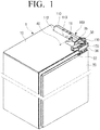
- FIG. 1 illustrates a perspective view of a built-in refrigerator including a wire cover unit according to at least one exemplary embodiment of the present disclosure
- FIG. 2 illustrates a plan view of a door of a built-in refrigerator 1 including a wire cover unit according to an exemplary embodiment of the present disclosure in a closed state
- FIG. 3 illustrates a plan view of a door of a built-in refrigerator including a wire cover unit according to certain embodiments of the present disclosure, in an opened state.
- a built-in refrigerator 1 includes a body 10, a door 20, a hinge 30, and a wire cover unit 100.
- the built-in refrigerator 1 may be installed on a wall surface or in a space provided between the kitchen cabinetry.
- the body 10 may include an opened one surface and includes storage space therein.
- the door 20 is, in some embodiments, connected to one corner of the opened surface of the body 10 by the hinge 30.
- the door 20 may include electronic devices (not shown) such as a display, a temperature control button, and the like, and a wire passing hole 22.
- the wire for supplying power to the electronic device or transmitting and receiving signals to and from the electronic device supplies the power or transmits and receives the signals to and from the electronic device through the wire passing hole 22.
- the hinge 30 may be a multi-joint hinge. According to certain embodiments, body frame 35 and a door frame 36 of the hinge 30 are coupled to the body 10 and the door 20, respectively. Since the built-in refrigerator 1 can be arranged on the wall surface or in the space between the kitchen cabinetry, a side surface of the built-in refrigerator 1 may have almost no free space. Therefore, when a rotary door hinge performing only a rotary motion is used, an outer portion of the door may strike or impinge upon the kitchen cabinetry or the wall surface.
- the hinge 30 connecting the body 10 and the door 20 of the built-in refrigerator 1 be a multi-joint hinge.
- the multi-joint may simultaneously perform a forward motion and a rotary motion. That is, when the door 20 is opened, the door 20 may move to a front of the body 10 and perform the rotary motion at the same time. Since the door 20 is operated to be opened while moving to the front of the body 10, the outer portion of the door 20 may avoid the striking or otherwise impinging upon the kitchen cabinetry or the wall surface.
- the wire cover unit 100 includes a case 110, a sliding member 130, and a fixing bracket 150.
- the case 110 can include a space in which the wire drawn from the body 10 is positioned and is coupled to a top surface of the body 10.
- one end of the case 110 may be hooked to the top surface of the body 10.
- a coupling groove 15 of the top surface of the body 10 and an inserting protrusion 112 of a rear surface portion of the case are hooked to each other to fix one end of the case 110 to the top surface of the body 10.
- the top surface of the body 10 and a side surface of the case 110 are connected to each other by one or more screws. It may be undesirable and/or difficult for the built-in refrigerator 1 to incorporate a screw which fastens to the case 110 from a side which is adjacent to the wall surface. The reason is because depending on the overall profile of built-in refrigerator and the installation site, the gap between the side surface of the case 110 and a wall surface may be very narrow. Therefore, a screw 40 may fastened to a body screw groove 11 in a direction from the center of the body 10 toward the wall surface.
- a portion of the wire drawn from the top surface of the body 10 and positioned in the case 110 may be enclosed by a sliding member 130.
- the sliding member 130 can include a space in which the wire is mounted.
- the sliding member 130 is connected to the fixing bracket 150 by a rotatable hinge 152 (see FIG. 2 ) at one end thereof, and includes an opening 131 (see FIG. 4 ) so that the wire is drawn in a door direction.
- the wire drawn from the body 10 may be led into the other end of the sliding member 130 by the sliding member 130.
- the sliding member 130 is coupled to the door 20 or coupled to the fixing bracket 150 attached to the door 20 through the hinge 152. If there is no hinge 152 when the door 20 is opened from the body 10 and is rotated, the sliding member may be bent. In such cases, stress may be repeatedly applied to the sliding member 130 from the opening and closing of door 20, and the sliding member 130 may be subject to fatigue failure.
- one end of the sliding member 130 may hingeably coupled to the door 20 or the fixing bracket 150 to be rotatable. Further, since the sliding member 130 may be bent when the door 20 is fully opened, an ABS (acrylonitrile-butadiene-styrene) resin or similarly flexible material may be used.
- the length of the sliding member 130 may be determined depending on an advancing distance of the door 20. That is, according to some embodiments, the length of the sliding member 130 is determined to be longer than the advancing distance of the door 20 so that the wire is not exposed to the outside of the case 110.
- the fixing bracket 150 may be coupled to the door frame 36 of the multi-joint and is connected to the door 20.
- the fixing bracket 150 is hingeably connected to the sliding member 130. Therefore, when the door 20 of the built-in refrigerator is opened, the sliding member 130 may move in conjunction with a forward motion of the door 20.
- the fixing bracket 150 includes a wire guide that guides the wire drawn from the opening 131 of the sliding member 130 to a wire connection terminal 172 which is adjacent to the door or the wire passing hole 22 of the door 20.
- the wire may minimize its motion through the wire guide.
- a wire guide guides the wire to the wire passing hole 22 of the door 20 or the wire connection terminal 172 which is adjacent to the door 20.
- the wire cover unit 100 includes the fixing bracket 150.
- the fixing bracket 150 may be omitted.
- the sliding member 130 may be hingeably connected to the door frame 36 or may be hingeably connected to the door 20, and the wire passing hole 22 may be formed to be adjacent to the hinge.
- a structure of the multi-joint hinge according to certain embodiments of this disclosure will be now described and an opening and closing operation of the door 20 of the built-in refrigerator will be then described with reference to FIGS. 2 and 3 .
- the multi-joint hinge 30 includes a plurality of links 31, 32, 33 and 34.
- the multi-joint hinge 30 includes a main body link 31, a main door link 32, a sub body link 33, and a sub door link 34.
- the multi-joint hinge 30 further includes a body frame 35 attached to the body 10 and a door fixing frame 36 attached to the door 20.
- One end of the main body link 31 of the multi-joint hinge 30 is hingeably connected to the body frame 35 and the other end of the main body link 31 is connected to one end of the main door link 32.
- the other end of the main door link 32 is hingeably connected to the door frame 36.
- the other end of the main door link 32 may be configured to slide on the door frame 36.
- the multi-joint hinge may include only the main body link 31 and the main door link 32, and can present a problem that the opening and closing path of the door is varies.
- the opening and closing path can be limited by attaching the sub body link 33 and the sub door link 34.
- One end of the sub body link 33 is coupled to the body frame 35 of the body 10 and the other end of the sub body link 33 hingeably connected to the central portion of the sub door link 34.
- One end of the sub door link 34 may be hingeably connected to the central portion of the main body link 31 to limit a path of the main body link 31.
- the other end of the sub door link 34 is hingeably coupled to the door frame 36.
- the main body link 31, the main door link 32, the sub body link 33, and the sub door link 34 of the multi-joint hinge 30 can be organically coupled to each other to allow simultaneous forward and rotational movement along defined path(s). With the organic coupling between the respective links, the multi-joint hinge 30 may move the door 20 forward and rotate the door 20 at the same time while limiting a movement direction of the door 20 to one. By the multi-joint hinge 30, it is possible for the door 20 to avoid interference with the wall surface or the furniture closet when the door 20 is opened.
- an exposed length of the sliding member 130 may at its shortest. In this case, most of the sliding member 130 remains in the case 110.
- the links of the multi-joint hinge 30 are relaxed and the door 20 simultaneously performs the forward and rotary motions. Therefore, the distance between the hinge 152 of one end of the sliding member 130 and a portion from which the sliding member 130 of the case 110 is drawn is increased. That is, the sliding member 130 slides from the case 110 and is drawn to the outside. Since the advancing distance, a rotary direction, and a movement direction of the door 20 are limited by the multi-joint hinge 30, the distance of the sliding member 130 drawn from the case 110 is also limited. Since, according to certain embodiments, the length of the sliding member 130 is determined to be larger than a distance at which the sliding member 130 is maximally drawn, the entirety of the sliding member 130 need not be drawn to the outside of the case 110.
- a portion indicated by a dotted line illustrates a case in which the door 20 is opened by 90° or more based on the opened surface of the body 10.
- the sliding member 130 may be bent, and the sliding member 130 may be formed of a soft material such as ABS, a rubber, or the like to prevent the sliding member 130 from being damaged due to the bending.
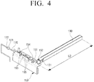
- FIG. 4 is a perspective view illustrating a wire cover unit 100 according to an exemplary embodiment of the present disclosure.
- one end of the sliding member 130 is hingeably connected to the fixing bracket 150.
- the opening 131 may be formed in a side surface of the sliding member at one end of the sliding member 130 and the wire 170 is drawn from the opening 131 of the sliding member 130.
- fixing bracket 150 includes a wire guide 151, and the wire guide 151 guides the wire drawn from the opening 131 to the wire connection terminal 172 which is adjacent to the door 20 or the wire passing hole 22 (see FIG. 1 ) included in the door.
- a wire connection terminal 171 which is adjacent to the sliding member 130 and is connectable to the wire connection terminal 172 which is adjacent to the door 20 may be included.
- the wire connection terminals 171 and 172 may be harness connectors.
- the wire guide 151 may include a pair of protruding pieces 153 and two or more fixing protrusions 154.
- the pair of protruding pieces 153 is disposed on the fixing bracket 150 to face each other.
- the wire may be disposed between the pair of protruding pieces 153.
- At least two or more fixing protrusions 155 fixing the wire 170 disposed between the pair of protruding pieces 153 may be further disposed on the fixing bracket 150.
- the wire 170 drawn from the opening 131 of the sliding member 130 is guided to the wire connection terminal 172 which is adjacent to the door 20 or the wire passing hole 22 by the pair of protruding pieces 153.
- a fixing member for fixing the wire 170 is required.
- the fixing protrusions 154 may be used as the fixing member for fixing the wire.
- a plurality of fixing protrusions 154 are disposed on the fixing bracket 150 and the wire 170 is disposed in a zigzag shape so as to be caught by the plurality of fixing protrusions 154, thereby limiting a motion of the wire 170 in a planar direction.
- wire guide 151 may have auxiliary protrusions 155 protruding from the protruding pieces 153.
- the auxiliary protrusions 155 may limit vertical motion of the wire 170.
- the wire guide 151 may have a plurality of protruding pieces 153, the fixing protrusions 154, and the like to fix the wire 170 to a top surface of the fixing bracket 150.
- the fixing member for fixing is not limited to the protruding pieces 153, the fixing protrusion 154, the auxiliary protrusion 155, or the like, and may include a hook capable of fitting the wire 170, a through-type member attached to the fixing bracket 150 and enclosing the wire, and the like.
- a length L2 of the sliding member 130 may be determined in consideration of an installation position of the case and the advancing distance of the door 20. According to certain embodiments, it is desirable that length L2 of the sliding member 130 be determined to have a margin in which the wire 170 may move so that the wire 170 is not bent inside the case 110 at a position at which the sliding member 130 is retracted, such as when the door 20 is closed. Further, according to some embodiments, the length of the sliding member is determined to be longer than the maximum advancing distance L1 (see FIG. 3 ) of the door 20 so that a portion of the sliding member 130 is disposed to be within the drawn portion of the case 110 even at the maximum advancing distance of the door 20, when the door 20 is opened.
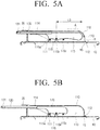
- FIGS. 5A and 5B illustrate cross-sectional views of an upper portion of the wire cover unit 100 and the body 10 of the built-in refrigerator 1 according to certain exemplary embodiments of the present disclosure
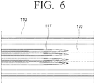
- FIG. 6 further illustrates, from a bottom view, part A of FIG. 5A
- FIG. 7 further illustrates, from an enlarged view, part B of FIG. 5A .
- FIG. 5A illustrates an arrangement of the sliding member 130 and the wire 170 in a state in which the door 20 is closed
- FIG. 5B illustrates an arrangement of the sliding member 130 and the wire 170 in a state in which the door 20 is opened.
- case 110 includes a storing portion 113 and a drawing portion 114.
- the case 110 may store the wire 170 to prevent the wire 170 from being exposed to the outside, and the drawing portion 114 has a shape corresponding to the sliding member 130 so that the sliding member 130 slides to draw the wire 170.
- storing portion 113 stores the wire 170 drawn from the top surface of the body 10.
- the storing portion 113 determines a movement position of the wire 170 and includes a wire fixing portion limiting a moving length of the wire 170.
- the moving length of the wire 170 is limited by installing the wire fixing portion and this is to prevent the wire 170 from being entangled in the storing portion 113.
- the wire fixing portion includes protruding members 115a, 115b, and 115c protruding on an inner surface of the storing portion 113.
- the protruding members 115a, 115b, and 115c may be plural, and the wire fixing portion may include a wire fixing protrusion 116 protruding below a position corresponding to one of the protruding members 115a, 115b, and 115c.
- the wire fixing portion may have surfaces of the protruding members 115a, 115b, and 115c that are in contact with the wire, which are curved surfaces, to minimize friction with the wire. That is, the protruding members 115a, 115b, and 115c of the wire fixing portion may be formed in a cylindrical shape. Further, the protruding members 115a, 115b, and 115c of the wire fixing portion may include a roller (not shown) to minimize the friction even in a case in which the motion of the wire 170 occurs in the case 110.
- wire 170 may be disposed in a zigzag shape above and below the plurality of protruding members 115a, 115b, and 115c.
- First to third protruding members 115a, 115b, and 115c may be sequentially disposed from a front surface.
- the wire 170 drawn from the top surface of the body 10 is disposed at upper ends of the first protruding member and third protruding member 115a and 115c, and may be disposed at a lower end of the second protruding member 115b.
- wire 170 is drawn to the outside of the case 110, since the wire 170 may be caught by the second protruding member 115b, it is possible to prevent the wire 170 from being disconnected because the wire 170 is drawn without any limitation and force is applied to the wire 170. Even if the maintenance of the wire 170 is performed, the protruding members 115a, 115b, and 115c may prevent the wire 170 from being drawn by a predetermined distance or more, thereby preventing the wire 170 inside the body 10 from being damaged.
- the wire fixing portion includes three protruding members 115a, 115b, and 115c as illustrated in FIG. 5A and FIG. 5B , in which case, the maximum drawing distance of the wire 170 is determined by a distance L3 from the second protruding member 115b to a position at which the wire is bent when the door 20 is closed.
- the wire 170 may be drawn approximately twice as longer as the distance L3.
- the protruding members 115a, 115b, and 115c may be disposed so that the drawing distance of the wire 170 is sufficient, and in a case in which the wire 170 may be separated by the connector at the middle, the protruding members 115a, 115b, and 115c may be disposed by taking into account only the drawing distance of the sliding member 130.
- a protruding portion 117 may be provided in a length direction of the case 110 to be linearly in contact with the wire 170 inside the case 110.
- FIG. 6 which illustrates, through an enlarged bottom view, part A of FIG. 5A , an upper bottom of the case 110 has a comb shaped protruding portion 117.
- the wire 170 is in contact with the case 110, and the wire 170 is in contact with a tip of the protruding portion 117.
- a contact area is reduced and the friction between the wire 170 and the case 110 is reduced as compared to a case in which the wire 170 is directly in contact with the case 110. Since resistance is small during the movement of the wire 170 due to allowing a direction of the protruding portion 117 of the comb-shape to coincide with a movement direction of the wire 170, it may be possible to prevent the wire from being damaged due to the friction between the wire 170 and the case 110.
- FIG. 5B illustrates a coupled portion between the case 110 and top surface of the body 10 according to some embodiments of the present disclosure.
- the top surface of the body 10 has a coupling groove 15 and one end of the case 110 has the inserting protrusion 112 having a shape corresponding to the coupling groove 15.
- the inserting protrusion 112 of the case is hooked to the coupling groove 15.
- One end portion of the case 110 is hooked to the coupling groove 15 as described above, and the side surface of the case 110 is screwed to the body as described above.
- a case screw groove 111 which is on the side surface of the case is illustrated in FIG. 5A and FIG. 5B .
- the case screw groove 111 is disposed at a position corresponding to the body screw groove 11 protruding on the top surface of the body 10, and the body 10 and the side surface of the case 110 are screwed to the respective screw grooves 11 and 111 externally from the central portion of the body 10.
- drawing portion 114 is utilized as a passage through which the sliding member 130 is drawn from and led to the outside of the case 110. Even in the case in which the door 20 is closed, the drawing portion 114 may have a sufficient length so that the sliding member 130 is not exposed.
- built-in refrigerator 1 is stored in a cabinetry or is installed in a refrigerator storage space of the wall surface.
- a strictly rotary hinge is used in the built-in refrigerator 1, where door 20 is fully opened, interference between the wall surface or the furniture closet and a movement path of the door 20 occurs, thereby causing a case in which the door 20 is not fully opened.
- the door 20 of the built-in refrigerator 1 may be connected to the body 10 by the multi-joint hinge 30. Even in the case of the rotary hinge performing only a general rotary motion, there may be movement and exposure of the wire.
- the operation of the built-in refrigerator 1 the door 20 and the body 10 are connected to each other by the multi-joint 30 as illustrated in the drawings.
- FIGS. 1 , 2 , 5A and 5B A state in which the door 20 of the built-in refrigerator 1 is closed will be described with reference to FIGS. 1 , 2 , 5A and 5B .
- links 31, 32, 33, and 34 of the multi-link hinge 30 are contracted to each other.
- the wire 170 drawn from the top surface of the body 10 of the built-in refrigerator 1 is stored in the storing portion 113 of the case 110, and a portion of the stored wire 170 is enclosed by the sliding member 130 that slides on the drawing portion 114 of the case 110.
- the wire 170 may be drawn through the opening 131 in a door direction of the sliding member 130, and the drawn wire 170 is guided to the wire passing hole 22 of the door 20 along the guidance of the fixing bracket 150.
- the wire 170 may be connected to an electronic device through the wire passing hole 22, and may supply power to the electronic device such as a display, a light apparatus dial, a lighting of the dial, or the like which is in the door 20, or transmit and receive signals according to an operation of the display or the dial with a controller (not shown).
- a controller not shown
- the protruding members 115a, 115b, and 115c are provided to prevent twisting of the wire 170 or entangling between the wires. Since the protruding members 115a, 115b, and 115c limit the movement length of the wire 170 according to the opening and closing of the door 20 and only the wire 170 of the limited length moves, the protruding members 115a, 115b, and 115c may prevent the twisting or entangling of the wire 170.
- FIGS. 1 , 3 , 5A and 5B A process of opening the door 20 of the built-in refrigerator 1 and a state in which the door 20 of the built-in refrigerator 1 is opened, according to certain embodiments of the present disclosure will be described with reference to FIGS. 1 , 3 , 5A and 5B
- the multi-joint hinge 30 starts to be relaxed. Since the multi-joint hinge 30 has the respective links 31, 32, 33, and 34 which are connected to each other, the movement path of the door 20 is determined as described above. That is, the door fixing frame 36 of the multi-joint hinge 30 has one movement path based on the body frame 35.
- door 20 performs an advance movement by the multi-joint hinge 30 being relaxed. Since the main door link 32 and the sub door link 34 are hinge-connected to the door fixing frame 36, they involve the rotary movement. Therefore, the door 20 simultaneously performs the advance and rotary movements.
- the sliding member 130 slides in the door direction from the wire cover unit 100 and is drawn by the advanced distance L1 of the door 20. Since the length of the sliding member 130 is determined by taking account into the movement distance L1 of the door 20, the wire 170 is not exposed between the sliding member 130 and the case 110. Since the wire 170 is not exposed, friction between an external object and the wire 170 may be reduced, and wear and damage of the wire 170 may be reduced.
- the storing portion of the case 110 keeps a sufficient length of wire 170 which may be moved by taking account into the drawn length of the wire 170, force pulling the wire 170 by the opened door 20, that is, tensile force applied to the wire 170 may be minimized. Therefore, a damage risk of the wire 170 may be reduced.
- the plurality of protruding members 115a, 115b, and 115c when the wire 170 moves in the case 110, the plurality of protruding members 115a, 115b, and 115c have the curved surface or are configured as the cylindrical roller, thereby reducing the friction between the plurality of protruding members 115a, 115b, and 115c and the wire 170 inside the case 110.
- the door 20 When the door 20 is fully opened, in some embodiments, the door 20 is opened as indicated by the dotted line of FIG. 3 .
- a predominantly opened position of the door 20 is determined according to a movement range of the multi-joint hinge 30.
- the sliding member 130 When the door 20 is fully opened and an angle between the opened surface of the body 10 and the door 20 is an obtuse angle, the sliding member 130 is bent. If the sliding member 130 is weak in softness, since sliding member 130 may be damaged, it is preferable that the sliding member 130 is formed of a soft material.
- the wire cover unit 100 includes the case 110, the sliding member 130, and the fixing bracket 150.
- the sliding member 130 and the fixing bracket 150 which are hingeably connected to each other are provided.
- the wire 170 is disposed on the protruding members 115a, 115b, and 115c of the case 110 in the zigzag shape, and the margin taking account into the movement length of the wire 170 is stored in the storing portion 113. A portion of the stored wire 170 is disposed to be exposed to the outside through the drawing portion 114.
- the inserting protrusion 112 of the case 110 is inserted into the coupling groove 15 of the top surface of the body 10 and is hooked thereto.
- the body screw groove 11 protruding from the body 10 and a corresponding case screw groove 111 are aligned to coincide with each other, and the screw is coupled to the screw grooves 11 and 111 in an outward direction from the center of the body 10.
- the sliding member 130 can be installed to protect the wire 170 drawn from the case 110.
- wire 170 drawn from the case is inserted into the sliding member 130, and the sliding member 130 slides into the case 110 through the drawing portion 114. Thereafter, the fixing bracket 150 which is hingeably connected to the sliding member 130 is coupled to the door frame 36, thereby mounting the wire cover unit 100 in the built-in refrigerator 1. Thereafter, the wire 170 is connected through the wire connection terminal (harness).
- An operation of disassembling the wire cover unit 100 may be performed in the reverse order of the mounting operation for maintenance or replacement of the wire 170 provided in the built-in refrigerator 1.
- the wire cover unit 100 may be mounted in a device such as a built-in microwave oven, a built-in styler, or the like having a door 20 which includes a device requiring power such as a display or including a dial button requiring transmission and reception of signals.
- a device such as a built-in microwave oven, a built-in styler, or the like having a door 20 which includes a device requiring power such as a display or including a dial button requiring transmission and reception of signals.
- the wire cover unit 100 includes the sliding member 130 and the case 110, and the wire 170 may be drawn through the sliding member 130 in conjunction with the movement of the door 20 according to the motion of the multi-joint hinge 30.
- the external exposure of the wire 170 may be minimized, the damage risk due to the friction with the external object is reduced, and there is an advantage in that an appearance is good.
- the wire cover unit has the protruding members 115a, 115b, and 115c inside the case 110 and has the protruding portion 117 in the length direction of the case, the friction due to the movement of the wire 170 may be reduced and the damage risk due to the movement of the wire may also be reduced.
Landscapes
- Engineering & Computer Science (AREA)
- Mechanical Engineering (AREA)
- Chemical & Material Sciences (AREA)
- Combustion & Propulsion (AREA)
- Physics & Mathematics (AREA)
- Thermal Sciences (AREA)
- General Engineering & Computer Science (AREA)
- Refrigerator Housings (AREA)
Applications Claiming Priority (1)
| Application Number | Priority Date | Filing Date | Title |
|---|---|---|---|
| KR1020170000907A KR102253487B1 (ko) | 2017-01-03 | 2017-01-03 | 전선커버유닛을 포함하는 빌트인 냉장고 |
Publications (3)
| Publication Number | Publication Date |
|---|---|
| EP3343152A1 true EP3343152A1 (de) | 2018-07-04 |
| EP3343152C0 EP3343152C0 (de) | 2025-07-09 |
| EP3343152B1 EP3343152B1 (de) | 2025-07-09 |
Family
ID=60811866
Family Applications (1)
| Application Number | Title | Priority Date | Filing Date |
|---|---|---|---|
| EP17210033.1A Active EP3343152B1 (de) | 2017-01-03 | 2017-12-22 | Einbaukühlschrank mit kabelabdeckeinheit |
Country Status (4)
| Country | Link |
|---|---|
| US (2) | US10563904B2 (de) |
| EP (1) | EP3343152B1 (de) |
| KR (1) | KR102253487B1 (de) |
| CN (1) | CN108266954B (de) |
Cited By (6)
| Publication number | Priority date | Publication date | Assignee | Title |
|---|---|---|---|---|
| CN112444030A (zh) * | 2019-08-28 | 2021-03-05 | 青岛海尔电冰箱有限公司 | 带有走线模块的冰箱 |
| EP3957936A1 (de) * | 2020-08-18 | 2022-02-23 | LG Electronics Inc. | Kühlschrank |
| AT525246A4 (de) * | 2021-12-21 | 2023-02-15 | Blum Gmbh Julius | Beschlag zur bewegbaren Lagerung eines Schwenkelements |
| AU2021209313B2 (en) * | 2020-07-30 | 2023-08-10 | Eptech Co., Ltd. | Multi-joint link hinge and refrigerator including the same |
| EP4257900A4 (de) * | 2020-12-07 | 2024-05-08 | Haier Smart Home Co., Ltd. | Lineare scharnieranordnung für ein gerät |
| US12442587B2 (en) * | 2021-01-06 | 2025-10-14 | Lg Electronics Inc. | Refrigerator |
Families Citing this family (25)
| Publication number | Priority date | Publication date | Assignee | Title |
|---|---|---|---|---|
| US10830525B2 (en) | 2016-10-17 | 2020-11-10 | Whirlpool Corporation | Hinge assembly |
| US10544983B2 (en) * | 2017-01-03 | 2020-01-28 | Samsung Electronics Co., Ltd. | Refrigerator |
| KR102412060B1 (ko) | 2017-04-26 | 2022-06-23 | 엘지전자 주식회사 | 냉장고 |
| US11091943B2 (en) * | 2018-12-29 | 2021-08-17 | Whirlpool Corporation | Articulating wire chase for use with an articulating hinge for an appliance door |
| KR20220085383A (ko) | 2020-12-15 | 2022-06-22 | 엘지전자 주식회사 | 냉장고 |
| KR20220085384A (ko) | 2020-12-15 | 2022-06-22 | 엘지전자 주식회사 | 냉장고 |
| KR20220085385A (ko) * | 2020-12-15 | 2022-06-22 | 엘지전자 주식회사 | 냉장고 |
| KR20220099332A (ko) * | 2021-01-06 | 2022-07-13 | 엘지전자 주식회사 | 냉장고 |
| KR20220099328A (ko) * | 2021-01-06 | 2022-07-13 | 엘지전자 주식회사 | 냉장고 |
| KR20220099330A (ko) | 2021-01-06 | 2022-07-13 | 엘지전자 주식회사 | 냉장고 |
| KR20230038048A (ko) * | 2021-09-10 | 2023-03-17 | 삼성전자주식회사 | 냉장고 |
| WO2023098200A1 (zh) * | 2021-12-03 | 2023-06-08 | 青岛海尔电冰箱有限公司 | 具有走线模块的冰箱 |
| CN116222069B (zh) * | 2021-12-03 | 2025-09-09 | 青岛海尔电冰箱有限公司 | 具有与箱体相装配的走线组件的冰箱 |
| CN116222067A (zh) * | 2021-12-03 | 2023-06-06 | 青岛海尔电冰箱有限公司 | 具有可伸缩的走线模块的冰箱 |
| CN116222066B (zh) * | 2021-12-03 | 2025-10-17 | 青岛海尔电冰箱有限公司 | 具有绕线装置的冰箱 |
| CN116222064B (zh) * | 2021-12-03 | 2025-11-11 | 青岛海尔电冰箱有限公司 | 具有收线结构的冰箱 |
| CN116294344B (zh) * | 2021-12-03 | 2025-09-09 | 青岛海尔电冰箱有限公司 | 具有走线模块的冰箱 |
| CN117128685A (zh) * | 2022-05-20 | 2023-11-28 | 青岛海尔电冰箱有限公司 | 冰箱 |
| KR20240018273A (ko) | 2022-08-02 | 2024-02-13 | 엘지전자 주식회사 | 조리기기 |
| KR20240018266A (ko) | 2022-08-02 | 2024-02-13 | 엘지전자 주식회사 | 조리기기 |
| WO2024029727A1 (ko) * | 2022-08-03 | 2024-02-08 | 삼성전자주식회사 | 냉장고 |
| KR20240113135A (ko) * | 2023-01-13 | 2024-07-22 | 삼성전자주식회사 | 냉장고 |
| CN119998609A (zh) * | 2023-01-13 | 2025-05-13 | 三星电子株式会社 | 冰箱 |
| CN116182458B (zh) * | 2023-03-08 | 2024-10-29 | 海信冰箱有限公司 | 嵌入式冰箱 |
| EP4697884A1 (de) * | 2023-05-12 | 2026-02-18 | Samsung Electronics Co., Ltd. | Elektronische vorrichtung mit diskontinuierlichem teil zur verschiebung der parasitären resonanzfrequenz |
Citations (12)
| Publication number | Priority date | Publication date | Assignee | Title |
|---|---|---|---|---|
| US3788094A (en) * | 1972-12-01 | 1974-01-29 | Gen Motors Corp | Waterline retractor for refrigerator cabinet |
| US3792189A (en) * | 1972-02-11 | 1974-02-12 | Messerschmitt Boelkow Blohm | Telescopic cable guide |
| JPH02146490A (ja) * | 1988-11-28 | 1990-06-05 | Hitachi Ltd | 冷蔵庫 |
| DE69323392T2 (de) * | 1992-11-12 | 1999-09-09 | General Electric Co. | Kühlschrank mit Zufuhrvorrichtung einer, in einer Tür angeordneten, Ausgabeeinrichtung |
| DE202008006133U1 (de) * | 2007-06-09 | 2008-10-23 | Liebherr-Hausgeräte Ochsenhausen GmbH | Kühl- und/oder Gefriergerät |
| US20090289536A1 (en) * | 2006-07-06 | 2009-11-26 | Lg Electronics Inc. | Refrigerator |
| US20130092802A1 (en) * | 2011-10-13 | 2013-04-18 | Andrew J. Doberstein | Line Extender/Retractor |
| US20130212835A1 (en) * | 2012-02-17 | 2013-08-22 | Oreste Lanzani | Hinge For A Household Appliance With Improved Elastically Deformable Means |
| US20140210328A1 (en) * | 2013-01-30 | 2014-07-31 | BSH Bosch und Siemens Hausgeräte GmbH | Home appliance comprising a transfer element between a body and a door thereof |
| WO2014154252A1 (en) * | 2013-03-26 | 2014-10-02 | Arcelik Anonim Sirketi | Cooling device hinge mechanism and cable installation device |
| US20140319990A1 (en) * | 2013-04-29 | 2014-10-30 | Whirlpool Corporation | Appliance with closure element having an operative device |
| CN104466826A (zh) * | 2014-11-26 | 2015-03-25 | 珠海格力电器股份有限公司 | 一种门体铰链线束约束结构及冰箱 |
Family Cites Families (27)
| Publication number | Priority date | Publication date | Assignee | Title |
|---|---|---|---|---|
| US3396282A (en) * | 1965-08-20 | 1968-08-06 | Rca Corp | Time delay circuit employing logic gate |
| KR0136613Y1 (ko) | 1995-08-19 | 1999-03-20 | 구자홍 | 냉장고의 전선연결구조 |
| US5787724A (en) * | 1997-06-04 | 1998-08-04 | Maytag Corporation | Dispensing assembly for top mount refrigerator |
| US5941619A (en) * | 1997-09-24 | 1999-08-24 | White Consolidated Industries, Inc. | Electrical connector for a refrigerator and method of installing |
| US20030090182A1 (en) * | 2001-11-14 | 2003-05-15 | Johnson Kristianne E. | Interchangeable customized bezel |
| US7623115B2 (en) * | 2002-07-27 | 2009-11-24 | Sony Computer Entertainment Inc. | Method and apparatus for light input device |
| US20060017361A1 (en) * | 2004-07-23 | 2006-01-26 | Robert Rendel | Hinge conduit casing |
| KR100606731B1 (ko) | 2004-11-10 | 2006-08-01 | 엘지전자 주식회사 | 냉장고 |
| TWI360539B (en) * | 2004-10-28 | 2012-03-21 | Shionogi & Co | 3-carbamoyl-2-pyridone derivatives |
| KR100596569B1 (ko) | 2004-12-06 | 2006-07-05 | 삼성전자주식회사 | 냉장고 |
| KR100872226B1 (ko) * | 2007-04-20 | 2008-12-05 | 엘지전자 주식회사 | 냉장고 |
| KR101349986B1 (ko) * | 2007-05-23 | 2014-01-24 | 엘지전자 주식회사 | 냉장고의 리드와이어 연결구조 |
| KR101831614B1 (ko) * | 2010-01-28 | 2018-02-26 | 삼성전자주식회사 | 냉장고 |
| CA2806678A1 (en) | 2010-08-30 | 2012-03-08 | St. Jude Medical Puerto Rico Llc | Disengagable cam system for tissue puncture closure device |
| US20120080991A1 (en) * | 2010-10-05 | 2012-04-05 | General Electric Company | Consumer appliance with finger guard |
| US20120242207A1 (en) * | 2011-03-22 | 2012-09-27 | Martin Mershon | Connection point for communication device on appliance |
| KR101849106B1 (ko) * | 2011-08-23 | 2018-06-01 | 삼성전자주식회사 | 냉장고 |
| JP6092027B2 (ja) * | 2013-07-12 | 2017-03-08 | 東芝ライフスタイル株式会社 | 冷蔵庫 |
| ITTO20130710A1 (it) | 2013-09-02 | 2015-03-03 | Indesit Co Spa | Apparecchio di refrigerazione con passaggio per elemento tubolare flessibile tra armadio e porta |
| DE102014114177A1 (de) * | 2014-09-30 | 2016-03-31 | Miele & Cie. Kg | Haushaltsgerät mit zwei oder mehreren Geräteeinheiten |
| CN204118531U (zh) * | 2014-10-23 | 2015-01-21 | 国家电网公司 | 改善端子箱门关合问题的连杆装置 |
| CN204316032U (zh) * | 2014-11-26 | 2015-05-06 | 珠海格力电器股份有限公司 | 一种门体铰链线束约束结构及冰箱 |
| KR102100252B1 (ko) * | 2015-01-05 | 2020-04-13 | 삼성전자주식회사 | 냉장고 |
| US10386111B2 (en) * | 2016-11-30 | 2019-08-20 | Bsh Hausgeraete Gmbh | Home appliance device and method for assembling a home appliance device |
| US20180156519A1 (en) * | 2016-12-02 | 2018-06-07 | Bsh Hausgeraete Gmbh | Home Appliance Device |
| KR102412060B1 (ko) * | 2017-04-26 | 2022-06-23 | 엘지전자 주식회사 | 냉장고 |
| US11091943B2 (en) * | 2018-12-29 | 2021-08-17 | Whirlpool Corporation | Articulating wire chase for use with an articulating hinge for an appliance door |
-
2017
- 2017-01-03 KR KR1020170000907A patent/KR102253487B1/ko active Active
- 2017-12-22 EP EP17210033.1A patent/EP3343152B1/de active Active
-
2018
- 2018-01-03 CN CN201810004685.5A patent/CN108266954B/zh active Active
- 2018-01-03 US US15/861,591 patent/US10563904B2/en active Active
-
2020
- 2020-01-16 US US16/744,978 patent/US11047612B2/en active Active
Patent Citations (12)
| Publication number | Priority date | Publication date | Assignee | Title |
|---|---|---|---|---|
| US3792189A (en) * | 1972-02-11 | 1974-02-12 | Messerschmitt Boelkow Blohm | Telescopic cable guide |
| US3788094A (en) * | 1972-12-01 | 1974-01-29 | Gen Motors Corp | Waterline retractor for refrigerator cabinet |
| JPH02146490A (ja) * | 1988-11-28 | 1990-06-05 | Hitachi Ltd | 冷蔵庫 |
| DE69323392T2 (de) * | 1992-11-12 | 1999-09-09 | General Electric Co. | Kühlschrank mit Zufuhrvorrichtung einer, in einer Tür angeordneten, Ausgabeeinrichtung |
| US20090289536A1 (en) * | 2006-07-06 | 2009-11-26 | Lg Electronics Inc. | Refrigerator |
| DE202008006133U1 (de) * | 2007-06-09 | 2008-10-23 | Liebherr-Hausgeräte Ochsenhausen GmbH | Kühl- und/oder Gefriergerät |
| US20130092802A1 (en) * | 2011-10-13 | 2013-04-18 | Andrew J. Doberstein | Line Extender/Retractor |
| US20130212835A1 (en) * | 2012-02-17 | 2013-08-22 | Oreste Lanzani | Hinge For A Household Appliance With Improved Elastically Deformable Means |
| US20140210328A1 (en) * | 2013-01-30 | 2014-07-31 | BSH Bosch und Siemens Hausgeräte GmbH | Home appliance comprising a transfer element between a body and a door thereof |
| WO2014154252A1 (en) * | 2013-03-26 | 2014-10-02 | Arcelik Anonim Sirketi | Cooling device hinge mechanism and cable installation device |
| US20140319990A1 (en) * | 2013-04-29 | 2014-10-30 | Whirlpool Corporation | Appliance with closure element having an operative device |
| CN104466826A (zh) * | 2014-11-26 | 2015-03-25 | 珠海格力电器股份有限公司 | 一种门体铰链线束约束结构及冰箱 |
Cited By (15)
| Publication number | Priority date | Publication date | Assignee | Title |
|---|---|---|---|---|
| CN112444030B (zh) * | 2019-08-28 | 2022-11-08 | 青岛海尔电冰箱有限公司 | 带有走线模块的冰箱 |
| CN112444030A (zh) * | 2019-08-28 | 2021-03-05 | 青岛海尔电冰箱有限公司 | 带有走线模块的冰箱 |
| US12449187B2 (en) | 2020-07-30 | 2025-10-21 | Lg Electronics Inc. | Multi-joint link hinge and refrigerator including the same |
| AU2021209313B2 (en) * | 2020-07-30 | 2023-08-10 | Eptech Co., Ltd. | Multi-joint link hinge and refrigerator including the same |
| US12130072B2 (en) | 2020-07-30 | 2024-10-29 | Lg Electronics Inc. | Multi-joint link hinge and refrigerator including the same |
| US12181207B2 (en) | 2020-08-18 | 2024-12-31 | Lg Electronics Inc. | Refrigerator |
| EP3957936A1 (de) * | 2020-08-18 | 2022-02-23 | LG Electronics Inc. | Kühlschrank |
| AU2021215170B2 (en) * | 2020-08-18 | 2023-06-15 | Lg Electronics Inc. | Refrigerator |
| US11774165B2 (en) | 2020-08-18 | 2023-10-03 | Lg Electronics Inc. | Refrigerator |
| EP4368927A3 (de) * | 2020-08-18 | 2024-06-26 | LG Electronics Inc. | Kühlschrank |
| EP4257900A4 (de) * | 2020-12-07 | 2024-05-08 | Haier Smart Home Co., Ltd. | Lineare scharnieranordnung für ein gerät |
| US12442587B2 (en) * | 2021-01-06 | 2025-10-14 | Lg Electronics Inc. | Refrigerator |
| AT525246A4 (de) * | 2021-12-21 | 2023-02-15 | Blum Gmbh Julius | Beschlag zur bewegbaren Lagerung eines Schwenkelements |
| WO2023115084A1 (de) | 2021-12-21 | 2023-06-29 | Julius Blum Gmbh | Beschlag zur bewegbaren lagerung eines schwenkelements |
| AT525246B1 (de) * | 2021-12-21 | 2023-02-15 | Blum Gmbh Julius | Beschlag zur bewegbaren Lagerung eines Schwenkelements |
Also Published As
| Publication number | Publication date |
|---|---|
| US11047612B2 (en) | 2021-06-29 |
| EP3343152C0 (de) | 2025-07-09 |
| US10563904B2 (en) | 2020-02-18 |
| EP3343152B1 (de) | 2025-07-09 |
| CN108266954A (zh) | 2018-07-10 |
| KR102253487B1 (ko) | 2021-05-18 |
| CN108266954B (zh) | 2021-07-16 |
| US20180187956A1 (en) | 2018-07-05 |
| KR20180080032A (ko) | 2018-07-11 |
| US20200149800A1 (en) | 2020-05-14 |
Similar Documents
| Publication | Publication Date | Title |
|---|---|---|
| US11047612B2 (en) | Built-in refrigerator including wire cover unit | |
| US10830528B2 (en) | Traveling harness system | |
| US10731411B2 (en) | End caps for architectural coverings | |
| US11181280B2 (en) | Door for a domestic appliance | |
| US8816525B2 (en) | Electric power supply device for sliding door | |
| EP1563234B1 (de) | Elektronisch gesteuerter kühlschrank mit einer tür dessen öffnungsrichtung geändert werden kann | |
| US20110056136A1 (en) | Apparatus for Transferring Electric Power Between a Closable Member and a Frame | |
| US11555349B2 (en) | Device for winding a screen having a hinged wall attachment | |
| WO2020134184A1 (zh) | 具有滑轨走线机构的冰箱 | |
| EP3255234A1 (de) | Scharnier mit dämpfungswirkung und vorrichtung mit diesem scharnier | |
| EP2960412A1 (de) | Scharnier für ein Haushaltsgerät | |
| CN108777464A (zh) | 一种电力电缆保护装置 | |
| KR100737469B1 (ko) | 차량의 무빙 와이어링 시스템 | |
| KR101113640B1 (ko) | 슬라이딩 도어용 와이어 하네스 프로텍터 | |
| KR20040049683A (ko) | 빌트인 냉장고의 힌지 어셈블리 | |
| CN107702404A (zh) | 冰箱 | |
| CN118870150A (zh) | 摄像头组件及冰箱 | |
| EP4438847A1 (de) | Betätigungsvorrichtung mit einem leiterplattenverdränger | |
| EP4230932B1 (de) | Kühl- und/oder gefriergerät | |
| CN223976272U (zh) | 冰箱 | |
| CN116222062A (zh) | 具有走线模块的冰箱 | |
| CN116222064B (zh) | 具有收线结构的冰箱 | |
| KR0122840Y1 (ko) | 냉장고용 도어의 리드와이어 연결장치 | |
| KR100608940B1 (ko) | 냉장고에 병합된 디스플레이의 리드와이어 설치구조 | |
| CN116222067A (zh) | 具有可伸缩的走线模块的冰箱 |
Legal Events
| Date | Code | Title | Description |
|---|---|---|---|
| PUAI | Public reference made under article 153(3) epc to a published international application that has entered the european phase |
Free format text: ORIGINAL CODE: 0009012 |
|
| STAA | Information on the status of an ep patent application or granted ep patent |
Free format text: STATUS: REQUEST FOR EXAMINATION WAS MADE |
|
| 17P | Request for examination filed |
Effective date: 20171222 |
|
| AK | Designated contracting states |
Kind code of ref document: A1 Designated state(s): AL AT BE BG CH CY CZ DE DK EE ES FI FR GB GR HR HU IE IS IT LI LT LU LV MC MK MT NL NO PL PT RO RS SE SI SK SM TR |
|
| AX | Request for extension of the european patent |
Extension state: BA ME |
|
| STAA | Information on the status of an ep patent application or granted ep patent |
Free format text: STATUS: EXAMINATION IS IN PROGRESS |
|
| 17Q | First examination report despatched |
Effective date: 20200211 |
|
| GRAP | Despatch of communication of intention to grant a patent |
Free format text: ORIGINAL CODE: EPIDOSNIGR1 |
|
| STAA | Information on the status of an ep patent application or granted ep patent |
Free format text: STATUS: GRANT OF PATENT IS INTENDED |
|
| INTG | Intention to grant announced |
Effective date: 20250207 |
|
| GRAS | Grant fee paid |
Free format text: ORIGINAL CODE: EPIDOSNIGR3 |
|
| GRAA | (expected) grant |
Free format text: ORIGINAL CODE: 0009210 |
|
| STAA | Information on the status of an ep patent application or granted ep patent |
Free format text: STATUS: THE PATENT HAS BEEN GRANTED |
|
| AK | Designated contracting states |
Kind code of ref document: B1 Designated state(s): AL AT BE BG CH CY CZ DE DK EE ES FI FR GB GR HR HU IE IS IT LI LT LU LV MC MK MT NL NO PL PT RO RS SE SI SK SM TR |
|
| REG | Reference to a national code |
Ref country code: GB Ref legal event code: FG4D |
|
| REG | Reference to a national code |
Ref country code: CH Ref legal event code: EP |
|
| REG | Reference to a national code |
Ref country code: IE Ref legal event code: FG4D |
|
| U01 | Request for unitary effect filed |
Effective date: 20250711 |
|
| U07 | Unitary effect registered |
Designated state(s): AT BE BG DE DK EE FI FR IT LT LU LV MT NL PT RO SE SI Effective date: 20250716 |
|
| PG25 | Lapsed in a contracting state [announced via postgrant information from national office to epo] |
Ref country code: IS Free format text: LAPSE BECAUSE OF FAILURE TO SUBMIT A TRANSLATION OF THE DESCRIPTION OR TO PAY THE FEE WITHIN THE PRESCRIBED TIME-LIMIT Effective date: 20251109 |
|
| PGFP | Annual fee paid to national office [announced via postgrant information from national office to epo] |
Ref country code: GB Payment date: 20251120 Year of fee payment: 9 |
|
| PG25 | Lapsed in a contracting state [announced via postgrant information from national office to epo] |
Ref country code: NO Free format text: LAPSE BECAUSE OF FAILURE TO SUBMIT A TRANSLATION OF THE DESCRIPTION OR TO PAY THE FEE WITHIN THE PRESCRIBED TIME-LIMIT Effective date: 20251009 |
|
| PG25 | Lapsed in a contracting state [announced via postgrant information from national office to epo] |
Ref country code: HR Free format text: LAPSE BECAUSE OF FAILURE TO SUBMIT A TRANSLATION OF THE DESCRIPTION OR TO PAY THE FEE WITHIN THE PRESCRIBED TIME-LIMIT Effective date: 20250709 |
|
| PG25 | Lapsed in a contracting state [announced via postgrant information from national office to epo] |
Ref country code: GR Free format text: LAPSE BECAUSE OF FAILURE TO SUBMIT A TRANSLATION OF THE DESCRIPTION OR TO PAY THE FEE WITHIN THE PRESCRIBED TIME-LIMIT Effective date: 20251010 |
|
| PG25 | Lapsed in a contracting state [announced via postgrant information from national office to epo] |
Ref country code: PL Free format text: LAPSE BECAUSE OF FAILURE TO SUBMIT A TRANSLATION OF THE DESCRIPTION OR TO PAY THE FEE WITHIN THE PRESCRIBED TIME-LIMIT Effective date: 20250709 |
|
| PG25 | Lapsed in a contracting state [announced via postgrant information from national office to epo] |
Ref country code: RS Free format text: LAPSE BECAUSE OF FAILURE TO SUBMIT A TRANSLATION OF THE DESCRIPTION OR TO PAY THE FEE WITHIN THE PRESCRIBED TIME-LIMIT Effective date: 20251009 |
|
| U20 | Renewal fee for the european patent with unitary effect paid |
Year of fee payment: 9 Effective date: 20251223 |
|
| PG25 | Lapsed in a contracting state [announced via postgrant information from national office to epo] |
Ref country code: ES Free format text: LAPSE BECAUSE OF FAILURE TO SUBMIT A TRANSLATION OF THE DESCRIPTION OR TO PAY THE FEE WITHIN THE PRESCRIBED TIME-LIMIT Effective date: 20250709 |
|
| PG25 | Lapsed in a contracting state [announced via postgrant information from national office to epo] |
Ref country code: SM Free format text: LAPSE BECAUSE OF FAILURE TO SUBMIT A TRANSLATION OF THE DESCRIPTION OR TO PAY THE FEE WITHIN THE PRESCRIBED TIME-LIMIT Effective date: 20250709 |
|
| PG25 | Lapsed in a contracting state [announced via postgrant information from national office to epo] |
Ref country code: CZ Free format text: LAPSE BECAUSE OF FAILURE TO SUBMIT A TRANSLATION OF THE DESCRIPTION OR TO PAY THE FEE WITHIN THE PRESCRIBED TIME-LIMIT Effective date: 20250709 |
|
| PG25 | Lapsed in a contracting state [announced via postgrant information from national office to epo] |
Ref country code: SK Free format text: LAPSE BECAUSE OF FAILURE TO SUBMIT A TRANSLATION OF THE DESCRIPTION OR TO PAY THE FEE WITHIN THE PRESCRIBED TIME-LIMIT Effective date: 20250709 |