EP3343162A1 - Appareil de dissipation thermique - Google Patents
Appareil de dissipation thermique Download PDFInfo
- Publication number
- EP3343162A1 EP3343162A1 EP17178032.3A EP17178032A EP3343162A1 EP 3343162 A1 EP3343162 A1 EP 3343162A1 EP 17178032 A EP17178032 A EP 17178032A EP 3343162 A1 EP3343162 A1 EP 3343162A1
- Authority
- EP
- European Patent Office
- Prior art keywords
- heat
- coupled
- dissipation apparatus
- base
- dissipater
- Prior art date
- Legal status (The legal status is an assumption and is not a legal conclusion. Google has not performed a legal analysis and makes no representation as to the accuracy of the status listed.)
- Granted
Links
Images



Classifications
-
- F—MECHANICAL ENGINEERING; LIGHTING; HEATING; WEAPONS; BLASTING
- F28—HEAT EXCHANGE IN GENERAL
- F28F—DETAILS OF HEAT-EXCHANGE AND HEAT-TRANSFER APPARATUS, OF GENERAL APPLICATION
- F28F3/00—Plate-like or laminated elements; Assemblies of plate-like or laminated elements
- F28F3/02—Elements or assemblies thereof with means for increasing heat-transfer area, e.g. with fins, with recesses, with corrugations
-
- H—ELECTRICITY
- H05—ELECTRIC TECHNIQUES NOT OTHERWISE PROVIDED FOR
- H05K—PRINTED CIRCUITS; CASINGS OR CONSTRUCTIONAL DETAILS OF ELECTRIC APPARATUS; MANUFACTURE OF ASSEMBLAGES OF ELECTRICAL COMPONENTS
- H05K7/00—Constructional details common to different types of electric apparatus
- H05K7/20—Modifications to facilitate cooling, ventilating, or heating
- H05K7/2039—Modifications to facilitate cooling, ventilating, or heating characterised by the heat transfer by conduction from the heat generating element to a dissipating body
-
- H—ELECTRICITY
- H05—ELECTRIC TECHNIQUES NOT OTHERWISE PROVIDED FOR
- H05K—PRINTED CIRCUITS; CASINGS OR CONSTRUCTIONAL DETAILS OF ELECTRIC APPARATUS; MANUFACTURE OF ASSEMBLAGES OF ELECTRICAL COMPONENTS
- H05K7/00—Constructional details common to different types of electric apparatus
- H05K7/20—Modifications to facilitate cooling, ventilating, or heating
- H05K7/2029—Modifications to facilitate cooling, ventilating, or heating using a liquid coolant with phase change in electronic enclosures
- H05K7/20336—Heat pipes, e.g. wicks or capillary pumps
-
- F—MECHANICAL ENGINEERING; LIGHTING; HEATING; WEAPONS; BLASTING
- F28—HEAT EXCHANGE IN GENERAL
- F28D—HEAT-EXCHANGE APPARATUS, NOT PROVIDED FOR IN ANOTHER SUBCLASS, IN WHICH THE HEAT-EXCHANGE MEDIA DO NOT COME INTO DIRECT CONTACT
- F28D15/00—Heat-exchange apparatus with the intermediate heat-transfer medium in closed tubes passing into or through the conduit walls ; Heat-exchange apparatus employing intermediate heat-transfer medium or bodies
- F28D15/02—Heat-exchange apparatus with the intermediate heat-transfer medium in closed tubes passing into or through the conduit walls ; Heat-exchange apparatus employing intermediate heat-transfer medium or bodies in which the medium condenses and evaporates, e.g. heat pipes
- F28D15/0266—Heat-exchange apparatus with the intermediate heat-transfer medium in closed tubes passing into or through the conduit walls ; Heat-exchange apparatus employing intermediate heat-transfer medium or bodies in which the medium condenses and evaporates, e.g. heat pipes with separate evaporating and condensing chambers connected by at least one conduit; Loop-type heat pipes; with multiple or common evaporating or condensing chambers
-
- F—MECHANICAL ENGINEERING; LIGHTING; HEATING; WEAPONS; BLASTING
- F28—HEAT EXCHANGE IN GENERAL
- F28D—HEAT-EXCHANGE APPARATUS, NOT PROVIDED FOR IN ANOTHER SUBCLASS, IN WHICH THE HEAT-EXCHANGE MEDIA DO NOT COME INTO DIRECT CONTACT
- F28D15/00—Heat-exchange apparatus with the intermediate heat-transfer medium in closed tubes passing into or through the conduit walls ; Heat-exchange apparatus employing intermediate heat-transfer medium or bodies
- F28D15/02—Heat-exchange apparatus with the intermediate heat-transfer medium in closed tubes passing into or through the conduit walls ; Heat-exchange apparatus employing intermediate heat-transfer medium or bodies in which the medium condenses and evaporates, e.g. heat pipes
- F28D15/0275—Arrangements for coupling heat-pipes together or with other structures, e.g. with base blocks; Heat pipe cores
-
- F—MECHANICAL ENGINEERING; LIGHTING; HEATING; WEAPONS; BLASTING
- F28—HEAT EXCHANGE IN GENERAL
- F28F—DETAILS OF HEAT-EXCHANGE AND HEAT-TRANSFER APPARATUS, OF GENERAL APPLICATION
- F28F3/00—Plate-like or laminated elements; Assemblies of plate-like or laminated elements
- F28F3/02—Elements or assemblies thereof with means for increasing heat-transfer area, e.g. with fins, with recesses, with corrugations
- F28F3/06—Elements or assemblies thereof with means for increasing heat-transfer area, e.g. with fins, with recesses, with corrugations the means being attachable to the element
-
- F—MECHANICAL ENGINEERING; LIGHTING; HEATING; WEAPONS; BLASTING
- F28—HEAT EXCHANGE IN GENERAL
- F28F—DETAILS OF HEAT-EXCHANGE AND HEAT-TRANSFER APPARATUS, OF GENERAL APPLICATION
- F28F3/00—Plate-like or laminated elements; Assemblies of plate-like or laminated elements
- F28F3/12—Elements constructed in the shape of a hollow panel, e.g. with channels
-
- H—ELECTRICITY
- H05—ELECTRIC TECHNIQUES NOT OTHERWISE PROVIDED FOR
- H05K—PRINTED CIRCUITS; CASINGS OR CONSTRUCTIONAL DETAILS OF ELECTRIC APPARATUS; MANUFACTURE OF ASSEMBLAGES OF ELECTRICAL COMPONENTS
- H05K7/00—Constructional details common to different types of electric apparatus
- H05K7/20—Modifications to facilitate cooling, ventilating, or heating
- H05K7/2039—Modifications to facilitate cooling, ventilating, or heating characterised by the heat transfer by conduction from the heat generating element to a dissipating body
- H05K7/20409—Outer radiating structures on heat dissipating housings, e.g. fins integrated with the housing
-
- F—MECHANICAL ENGINEERING; LIGHTING; HEATING; WEAPONS; BLASTING
- F28—HEAT EXCHANGE IN GENERAL
- F28F—DETAILS OF HEAT-EXCHANGE AND HEAT-TRANSFER APPARATUS, OF GENERAL APPLICATION
- F28F2215/00—Fins
- F28F2215/04—Assemblies of fins having different features, e.g. with different fin densities
-
- F—MECHANICAL ENGINEERING; LIGHTING; HEATING; WEAPONS; BLASTING
- F28—HEAT EXCHANGE IN GENERAL
- F28F—DETAILS OF HEAT-EXCHANGE AND HEAT-TRANSFER APPARATUS, OF GENERAL APPLICATION
- F28F2215/00—Fins
- F28F2215/06—Hollow fins; fins with internal circuits
-
- F—MECHANICAL ENGINEERING; LIGHTING; HEATING; WEAPONS; BLASTING
- F28—HEAT EXCHANGE IN GENERAL
- F28F—DETAILS OF HEAT-EXCHANGE AND HEAT-TRANSFER APPARATUS, OF GENERAL APPLICATION
- F28F2220/00—Closure means, e.g. end caps on header boxes or plugs on conduits
Definitions
- the subject matter herein generally relates to a heat dissipation apparatus. More specifically, the subject matter herein relates to a heat dissipation device having a portion extending away from the base.
- Heat sinks are commonly used with electronic devices to improve heat dissipation and/or heat rejection thereby increasing performance of the associated electronic devices.
- Heat sinks utilize fin arrays and/or an airflow across the fin array to increase the exposed surface area for rejecting heat from the electronic device to the environment.
- a heat dissipation apparatus can include a heat pipe and/or a vapor chamber within the base to abuttingly engage the electronic device to extract increase heat transfer away from the electronic device to the fin array.
- the base in such devices typically provides a limited surface area for implementing a heat pipe or vapor chamber.
- a heat dissipation apparatus having a base, a heat dissipater, and a plurality of fin arrays.
- the heat dissipater has at least one horizontal portion disposed in the base and at least one portion extending therefrom. At least one of the plurality of fin arrays coupled with the at least one horizontal portion of the heat dissipater and at least one of the plurality of fin arrays coupled with the at least one portion extending from the base of the heat dissipater.
- the at least one portion extending from the heat dissipater can be two vertically extending portions.
- the two vertically extending portions can be evenly spaced along the base and form a substantially twin "T" shape.
- the at least one portion extending from the heat dissipater can alternatively be three vertically extending portions.
- the heat dissipater can be a vapor chamber, or the heat dissipater can be a base plate coupled with one or more heat pipes.
- the base plate can form a bottom surface of the base.
- the one or more heat pipes can be a plurality of heat pipes, at least one heat pipe disposed in the at least one portion extending from the base and at least one heat pipe disposed in the at least one horizontal portion.
- the base plate can be a vapor chamber forming a bottom surface the base and one or more heat pipes forming the one or more portions extending from the vapor chamber.
- the at least one fin array coupled to with the at least one horizontal portion can extend substantially perpendicular to the horizontal portion and the at least one fin array coupled with the at least one portion extending from the base can extend substantially perpendicular to the extending portion.
- the at least one fin array coupled to with the at least one horizontal portion can radially extend relative to the horizontal portion and the at least one fin array coupled with the at least one extending portion can radially extend relative to the vertical portion.
- the base can has at least one horizontal portion having an upper surface and disposed in the base and at least one portion extending away from the upper surface. At least one of the plurality of fin arrays coupled with the at least one horizontal portion of the heat dissipater and at least one of the plurality of fin arrays coupled with the at least one portion extending away from the upper surface.
- Coupled is defined as connected, whether directly or indirectly through intervening components, and is not necessarily limited to physical connections.
- the connection can be such that the objects are permanently connected or releasably connected.
- substantially is defined to be essentially conforming to the particular dimension, shape or other word that substantially modifies, such that the component need not be exact.
- substantially cylindrical means that the object resembles a cylinder, but can have one or more deviations from a true cylinder.
- comprising means "including, but not necessarily limited to”; it specifically indicates open-ended inclusion or membership in a so-described combination, group, series and the like.
- the present disclosure relates to a heat dissipation apparatus having a base, a heat dissipater, and a plurality of fin arrays.
- the heat dissipater has at least one horizontal portion having an upper surface and disposed in the base and at least one portion extending away from the upper surface. At least one of the plurality of fin arrays coupled with the at least one horizontal portion of the heat dissipater and at least one of the plurality of fin arrays coupled with the at least one portion extending away from the upper surface.
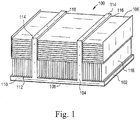
- FIG. 1 illustrates a heat dissipation apparatus 100.
- the heat dissipation apparatus 100 can have a base 102, a heat dissipater 104 and a plurality of fin arrays 106.
- the heat dissipation apparatus 100 can have a base 102 configured to receive at least a portion of the heat dissipater 104 therein.
- the base 102 can have a bottom surface 108 configured to abuttingly engage a heat source (not shown).
- the heat source can be an electronic device, such as a computer processing unit (CPU), microcontroller, graphic processing unit (GPU), or other heat generating device.
- CPU computer processing unit
- GPU graphic processing unit
- the bottom surface 108 can expose at least a portion of the heat dissipater 104 to the heat source and provide an abutting engagement between at least a portion of the heat dissipater 104 and the heat source.
- the base 102 can be formed from a thermally conductive material such as copper or aluminum to increase thermal heat conductive form the heat source to the heat dissipater 104.
- the heat dissipater 104 can have at least one horizontal portion 110 having an upper surface 112 and at least one vertical portion 114 extending away therefrom.
- the upper surface 112 can be coupled with one or more of the plurality of fin arrays 106.
- the at least one vertical portion 114 can have an exterior surface 116 and the exterior surface 116 can be coupled with one or more of the plurality of fin arrays 106.
- the at least one horizontal portion 110 is disposed in the base 102 and configured to be at least partially exposed to the heat source via the bottom surface 108 of the base 102.
- the heat dissipater 104 can formed of any thermally conductive material including, but not limited to copper, aluminum, or a combination thereof.
- the plurality of fin arrays 106 are coupled with the heat dissipater 104 and increase the rejection of thermal energy from the heat source to the environment. At least one of the plurality of fin arrays 106 can be coupled with the base 102, the at least one horizontal portion 110 of the heat dissipater 104, and/or the at least one vertical portion 114.
- the heat dissipater 104 having the horizontal portion 110 and the vertical portion 114 can reduce the overall length of each fin within a fin array 106, thus increasing the efficiency of the plurality of fin arrays 106 while maintaining the surface area of the plurality of fin arrays 106.
- the plurality of fin arrays 106 can increase the exposed surface area of the heat dissipater 104, thereby improving the rejection of thermal energy transferred from the heat source to the heat dissipater 104.
- the heat dissipation apparatus 100 can be implemented with a fan (not shown) generating an air flow across the plurality of fin arrays 106, thereby increasing heat transfer from the plurality of fin arrays 106 to the environment.
- Fan power requirements can be determined by the arrangement of the heat dissipation apparatus 100 and the pressure drop ( ⁇ p) associated with airflow across the heat dissipation apparatus 100. Fin thickness of the plurality of fin arrays 106 and arrangement and orientation of the plurality of fin arrays can alter the associated pressure drop and thus alter the fan power requirements for the heat dissipation apparatus.
- FIG. 2 illustrates an example embodiment of a heat dissipation apparatus 200.
- the heat dissipation apparatus 200 includes base 202 and a heat dissipater 204.
- the base 202 can have at least a portion of the heat dissipater 204 disposed therein.
- the head dissipater 204 is one or more heat pipes 208.
- the heat dissipater 204 can include at least one horizontal heat pipe 210 disposed in the base and at least one heat pipe 212 extending away therefrom. While the illustrated embodiment shows the at least one heat pipe 212 extending away from the base 202 in a substantially vertical arrangement, it is within the scope of this disclosure to vary the angle at which the at least one heat pipe 212 extends away from the base 202. In some instances, the at least one heat pipe 212 can extend away from the base at an angle between 15 degrees and 75 degrees.
- the heat pipe 208 can be a substantially circular tube having opposing ends.
- the heat pipe 208 is vacuum sealed tube having a working fluid disposed therein. As the working fluid absorbs thermal energy it boils to a vapor and travels from one end to the opposing end where it condenses back to a liquid, thus transferring the heat away from the one end and to the opposing end.
- the heat pipe 208 can also include a wicking material configured to allow the condensed working fluid to transition back to the one end of the heat pipe 208.
- the one end of the heat pipe 208 is adjacent and/or engaged with the heat source and the opposing end is disposed away from the heat source.
- the heat transfer of the heat pipe 208 is along the length of the heat pipe 208 from one end to the other, thus unidirectional.
- the heat pipe 208 can be made of any highly thermally conductive material, including but not limited to, copper, aluminum, or an alloy thereof. In some instances, at least a portion of the base 202 is constructed of a similarly
- the base 202 has two horizontal heat pipes 210 disposed therein and three substantially vertical heat pipes 212 extending away therefrom.
- the three heat pipes 212 extending away therefrom are spaced apart on the base 202.
- the horizontal heat pipes 210 coupled with the three substantially vertical heat pipes 212 forms a substantially "tri-T" arrangement.
- more or less than three substantially vertical heat pipes 212 can be implement to form other arrangements, for example two vertical heat pipes 212 forming a substantially "twin-T" arrangement.
- Each of the two horizontal heat pipes 210 and the three vertical heat pipes 212 can have a curved, or substantially U-shape, maximizing total length of the heat pipes 208.
- the two horizontal heat pipes can be placed within the base such that one horizontal heat pipe 210 has an end within an inner portion 214 of the substantially U shape formed by the other horizontal heat pipe 210.
- the heat dissipater 204 can have a plurality of fin arrays coupled to the one or more heat pipes 208.
- the plurality of fin arrays allows the one or more heat pipes 208 to efficiently dissipate the thermal energy absorbed by the one or more heat pipes 208 to the environment.
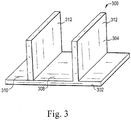
- FIGS. 3 and 4 illustrate an example embodiment of a heat dissipation apparatus 300.
- the heat dissipation apparatus 300 includes base 302 and a heat dissipater 304.
- the base 302 can have at least a portion of the heat dissipater 304 disposed therein.
- the head dissipater 304 can be one or more vapor chambers 308.
- the one or more vapor chambers 308 can be integrally formed with the base 302.
- the heat dissipater 304 can include at least one horizontal vapor chamber 310 disposed in the base 302 and at least one vapor chamber 312 extending away therefrom.
- the at least one horizontal vapor chamber 310 and the at least one vapor chamber 312 can be a single large vapor chamber having a substantially horizontal portion and portion extending away therefrom within a single vapor chamber 308. In other instances, the at least one horizontal vapor chamber 310 and the at least one vapor chamber 312 can be distinct vapor chambers 308 coupled one to the other.
- the illustrated embodiment shows the at least one vapor chamber 312 extending away from the base 302 in a substantially vertical arrangement, it is within the scope of this disclosure to vary the angle at which the at least one vapor chamber 312 extends away from the base 302. In some instances, the at least vapor chamber 312 can extend away from the base at an angle between 15 degrees and 75 degrees.
- the one or more vapor chambers 308 can be a vacuum sealed, substantially flat inner chamber 314 having a working fluid and wick material disposed therein.
- the vapor chamber 308 can abuttingly engage a heat source evaporating the working fluid and causing the gas to move within the inner chamber to a lower temperature causing the working fluid to condense and move within the wicking material back toward the heat source.
- the vapor chamber 308 allows heat transfer any direction within the vapor chamber 308, rather than directionally from one end to an opposing end.
- the vapor chamber 308 can be made of any highly thermally conductive material, including but not limited to, copper, aluminum, or an alloy thereof. In some instances, at least a portion of the base 302 is constructed of a similarly highly thermally conductive material.
- the base 302 has one horizontal vapor chamber 310 disposed therein and two substantially vertical vapor chambers 312 extending away therefrom.
- the two vapor chambers 312 extending away therefrom are spaced apart on the base 202 forming a substantially twin-T shaped arrangement.
- more than two substantially vertical vapor chambers 312 can be implemented to form other arrangements, for example three vertical vapor chambers 312 forming a substantially tri-T arrangement.
- the heat dissipater 304 can be formed from two folded plates 316, 318 coupled one to the other by soldering or diffusion bonding.
- the two folded plates 316, 318 are formed from copper and form a single three-dimensional vapor chamber 308.
- the heat dissipater 304 can have a plurality of fin arrays coupled to the one or more vapor chambers 308.
- the plurality of fin arrays allows the one or more vapor chambers 308 to efficiently dissipate the thermal energy absorbed by the one or more vapor chambers 308 to the environment.
- FIG. 5 illustrates a heat dissipation apparatus 100 having a plurality of fin arrays 106 coupled thereto.
- the plurality of fin arrays 106 can be coupled with the base 102, the heat dissipater 104, the horizontal portion 110, the vertical portion 114, or any combination thereof.
- the plurality of fin arrays 106 can include three vertically extending fin arrays 118 coupled with the horizontal portion 110 and three horizontally extending fin arrays 120 coupled with the vertical portion 114.
- the vertically extending fin arrays 118 can transfer heat away from the horizontal portion 110 and transfer it to the environment and the horizontally extending fin arrays 120 can transfer heat away from the vertical portion 114 and transfer it to the environment.
- the plurality of fin arrays 106 can be made from a thermally conductive material similar to that of the heat dissipater 104, such as copper or aluminum.
- any number of fin arrays 106 can be implemented in a vertical or horizontal arrangement without deviating from the scope of the present disclosure.
- the heat dissipation apparatus 100 can have two, four, five, six or any number of vertically extending fin arrays 118 in conjunction with two, four, five, six or any number of horizontally extending fin arrays 120.
- the plurality of fin arrays 106 are detailed in a vertical or horizontal arrangement, the plurality of fin arrays 106 can be disposed at any angle relative to the respective heat dissipater 104.
- each of the plurality of fin arrays 106 can radially extend away from the heat dissipater.
- horizontal, vertical, and a radially extending fin arrays 106 can be implemented together depending on the configuration of the heat dissipater 104.
Landscapes
- Engineering & Computer Science (AREA)
- Physics & Mathematics (AREA)
- Thermal Sciences (AREA)
- Mechanical Engineering (AREA)
- General Engineering & Computer Science (AREA)
- Microelectronics & Electronic Packaging (AREA)
- Life Sciences & Earth Sciences (AREA)
- Sustainable Development (AREA)
- Cooling Or The Like Of Semiconductors Or Solid State Devices (AREA)
- Cooling Or The Like Of Electrical Apparatus (AREA)
Applications Claiming Priority (1)
| Application Number | Priority Date | Filing Date | Title |
|---|---|---|---|
| US15/397,437 US20180192545A1 (en) | 2017-01-03 | 2017-01-03 | Heat dissipation apparatus |
Publications (2)
| Publication Number | Publication Date |
|---|---|
| EP3343162A1 true EP3343162A1 (fr) | 2018-07-04 |
| EP3343162B1 EP3343162B1 (fr) | 2021-03-03 |
Family
ID=59276511
Family Applications (1)
| Application Number | Title | Priority Date | Filing Date |
|---|---|---|---|
| EP17178032.3A Active EP3343162B1 (fr) | 2017-01-03 | 2017-06-27 | Appareil de dissipation thermique |
Country Status (5)
| Country | Link |
|---|---|
| US (1) | US20180192545A1 (fr) |
| EP (1) | EP3343162B1 (fr) |
| JP (1) | JP6503030B2 (fr) |
| CN (1) | CN108271332B (fr) |
| TW (1) | TWI622342B (fr) |
Families Citing this family (15)
| Publication number | Priority date | Publication date | Assignee | Title |
|---|---|---|---|---|
| WO2015157523A1 (fr) * | 2014-04-10 | 2015-10-15 | Advanced Thermal Solutions, Inc. | Dissipateur de chaleur à entrée d'écoulements multiples |
| US10045464B1 (en) * | 2017-03-31 | 2018-08-07 | International Business Machines Corporation | Heat pipe and vapor chamber heat dissipation |
| FI20195390A1 (en) * | 2019-05-10 | 2020-11-11 | Teknologian Tutkimuskeskus Vtt Oy | Electrical or optical component, coupler and heat transfer system |
| US11839057B2 (en) * | 2019-07-12 | 2023-12-05 | Samsung Electronics Co., Ltd | Apparatus with housing having structure for radiating heat |
| TWI703302B (zh) * | 2019-07-19 | 2020-09-01 | 大陸商深圳興奇宏科技有限公司 | 散熱裝置 |
| US11435144B2 (en) | 2019-08-05 | 2022-09-06 | Asia Vital Components (China) Co., Ltd. | Heat dissipation device |
| CN112542776B (zh) * | 2020-11-04 | 2022-12-06 | 国网河北省电力有限公司赵县供电分公司 | 一种高压开关柜散热辅助设备 |
| JP7542428B2 (ja) | 2020-12-24 | 2024-08-30 | 浜松ホトニクス株式会社 | ヒートシンク、活性エネルギ照射装置及び活性エネルギ照射システム |
| JP7029009B1 (ja) * | 2021-03-09 | 2022-03-02 | 古河電気工業株式会社 | ヒートシンク |
| US11632853B2 (en) * | 2021-03-15 | 2023-04-18 | Heatscape.Com, Inc. | Heatsink with perpendicular vapor chamber |
| CN214426509U (zh) * | 2021-03-18 | 2021-10-19 | 广东英维克技术有限公司 | 散热装置 |
| GB2608431A (en) * | 2021-07-01 | 2023-01-04 | Aptiv Tech Ltd | Power conductor and vehicle power distribution circuit incorporating the same |
| US12557251B1 (en) * | 2023-05-09 | 2026-02-17 | Brunswick Corporation | Chassis for electronic device |
| CN116880679A (zh) * | 2023-08-01 | 2023-10-13 | 深圳市美高电子设备有限公司 | 一种微型计算机散热系统 |
| US12566033B2 (en) * | 2023-12-08 | 2026-03-03 | JWS Technology CO., LTD. | Three-dimensional vapor chamber device |
Citations (7)
| Publication number | Priority date | Publication date | Assignee | Title |
|---|---|---|---|---|
| US20040052051A1 (en) * | 2002-09-17 | 2004-03-18 | Malone Christopher G. | Heat sink with heat pipe and base fins |
| US6945319B1 (en) * | 2004-09-10 | 2005-09-20 | Datech Technology Co., Ltd. | Symmetrical heat sink module with a heat pipe for spreading of heat |
| US20080121372A1 (en) * | 2006-11-24 | 2008-05-29 | Foxconn Technology Co., Ltd. | Heat dissipation device |
| US20090016023A1 (en) * | 2007-07-12 | 2009-01-15 | Foxconn Technology Co., Ltd. | Heat dissipation device with heat pipes |
| US20100078153A1 (en) * | 2002-05-15 | 2010-04-01 | Convergence Technologies (Usa), Llc | Vapor Augmented Heatsink with Multi-Wick Structure |
| US20130175021A1 (en) * | 2012-01-11 | 2013-07-11 | Fanuc Corporation | Servo amplifier with heat sink having two sets of heat-releasing plates perpendicular to each other |
| WO2013169033A1 (fr) * | 2012-05-11 | 2013-11-14 | Kim Yong Gil | Dispositif de rayonnement de chaleur pour appareil d'éclairage à diodes électroluminescentes |
Family Cites Families (24)
| Publication number | Priority date | Publication date | Assignee | Title |
|---|---|---|---|---|
| US3734177A (en) * | 1972-02-04 | 1973-05-22 | Modine Mfg Co | Heat exchanger |
| JPS55122362U (fr) * | 1979-02-21 | 1980-08-30 | ||
| US5216580A (en) * | 1992-01-14 | 1993-06-01 | Sun Microsystems, Inc. | Optimized integral heat pipe and electronic circuit module arrangement |
| JP2794154B2 (ja) * | 1993-06-04 | 1998-09-03 | ダイヤモンド電機 株式会社 | ヒートシンク |
| US5597034A (en) * | 1994-07-01 | 1997-01-28 | Digital Equipment Corporation | High performance fan heatsink assembly |
| IT1294293B1 (it) * | 1997-07-31 | 1999-03-24 | Maurizio Checchetti | Dissipatore di calore |
| US6189601B1 (en) * | 1999-05-05 | 2001-02-20 | Intel Corporation | Heat sink with a heat pipe for spreading of heat |
| US6490160B2 (en) * | 1999-07-15 | 2002-12-03 | Incep Technologies, Inc. | Vapor chamber with integrated pin array |
| JP2003336976A (ja) * | 2002-05-17 | 2003-11-28 | Furukawa Electric Co Ltd:The | ヒートシンクおよびその実装構造 |
| US7140422B2 (en) * | 2002-09-17 | 2006-11-28 | Hewlett-Packard Development Company, L.P. | Heat sink with heat pipe in direct contact with component |
| US7159649B2 (en) * | 2004-03-11 | 2007-01-09 | Thermal Corp. | Air-to-air heat exchanger |
| CN2727959Y (zh) * | 2004-08-14 | 2005-09-21 | 鸿富锦精密工业(深圳)有限公司 | 散热器 |
| TWM264539U (en) * | 2004-08-27 | 2005-05-11 | Hon Hai Prec Ind Co Ltd | Heat sink |
| WO2006035987A1 (fr) * | 2004-09-28 | 2006-04-06 | T.Rad Co., Ltd. | Échangeur de chaleur |
| US20060196640A1 (en) * | 2004-12-01 | 2006-09-07 | Convergence Technologies Limited | Vapor chamber with boiling-enhanced multi-wick structure |
| CN100456461C (zh) * | 2005-06-04 | 2009-01-28 | 富准精密工业(深圳)有限公司 | 热管散热装置 |
| CN100543972C (zh) * | 2005-08-08 | 2009-09-23 | 富准精密工业(深圳)有限公司 | 热管散热装置 |
| US7690418B2 (en) * | 2005-12-28 | 2010-04-06 | Fu Zhun Precision Industry (Shen Zhen) Co., Ltd. | Heat sink |
| JP4714638B2 (ja) * | 2006-05-25 | 2011-06-29 | 富士通株式会社 | ヒートシンク |
| WO2009108192A1 (fr) * | 2008-02-27 | 2009-09-03 | Hewlett-Packard Development Company, L.P. | Dissipateur thermique |
| CN201282616Y (zh) * | 2008-09-22 | 2009-07-29 | 富准精密工业(深圳)有限公司 | 散热装置 |
| JP2010251730A (ja) * | 2009-03-26 | 2010-11-04 | Marusan Denki:Kk | ヒートシンク |
| US9436235B2 (en) * | 2013-02-26 | 2016-09-06 | Nvidia Corporation | Heat sink with an integrated vapor chamber |
| JP3198319U (ja) * | 2015-04-16 | 2015-06-25 | 水谷電機工業株式会社 | 放熱器 |
-
2017
- 2017-01-03 US US15/397,437 patent/US20180192545A1/en not_active Abandoned
- 2017-05-11 TW TW106115649A patent/TWI622342B/zh active
- 2017-06-01 CN CN201710403107.4A patent/CN108271332B/zh active Active
- 2017-06-27 EP EP17178032.3A patent/EP3343162B1/fr active Active
- 2017-08-15 JP JP2017156837A patent/JP6503030B2/ja active Active
Patent Citations (7)
| Publication number | Priority date | Publication date | Assignee | Title |
|---|---|---|---|---|
| US20100078153A1 (en) * | 2002-05-15 | 2010-04-01 | Convergence Technologies (Usa), Llc | Vapor Augmented Heatsink with Multi-Wick Structure |
| US20040052051A1 (en) * | 2002-09-17 | 2004-03-18 | Malone Christopher G. | Heat sink with heat pipe and base fins |
| US6945319B1 (en) * | 2004-09-10 | 2005-09-20 | Datech Technology Co., Ltd. | Symmetrical heat sink module with a heat pipe for spreading of heat |
| US20080121372A1 (en) * | 2006-11-24 | 2008-05-29 | Foxconn Technology Co., Ltd. | Heat dissipation device |
| US20090016023A1 (en) * | 2007-07-12 | 2009-01-15 | Foxconn Technology Co., Ltd. | Heat dissipation device with heat pipes |
| US20130175021A1 (en) * | 2012-01-11 | 2013-07-11 | Fanuc Corporation | Servo amplifier with heat sink having two sets of heat-releasing plates perpendicular to each other |
| WO2013169033A1 (fr) * | 2012-05-11 | 2013-11-14 | Kim Yong Gil | Dispositif de rayonnement de chaleur pour appareil d'éclairage à diodes électroluminescentes |
Also Published As
| Publication number | Publication date |
|---|---|
| JP6503030B2 (ja) | 2019-04-17 |
| JP2018110211A (ja) | 2018-07-12 |
| EP3343162B1 (fr) | 2021-03-03 |
| TW201826913A (zh) | 2018-07-16 |
| US20180192545A1 (en) | 2018-07-05 |
| TWI622342B (zh) | 2018-04-21 |
| CN108271332A (zh) | 2018-07-10 |
| CN108271332B (zh) | 2019-08-23 |
Similar Documents
| Publication | Publication Date | Title |
|---|---|---|
| EP3343162B1 (fr) | Appareil de dissipation thermique | |
| US10410954B2 (en) | Cooling module, water-cooled cooling module and cooling system | |
| TWI765775B (zh) | 散熱裝置 | |
| CA2907056C (fr) | Dispositif de tuyau de chauffage dote d'ailettes liees sur la plaque de base hybride | |
| TWM517314U (zh) | 散熱裝置 | |
| EP3089210A1 (fr) | Module de refroidissement, module de refroidissement refroidi par eau et système de refroidissement | |
| CN107148192B (zh) | 热管模块及应用其的散热装置 | |
| TWM517315U (zh) | 散熱單元 | |
| US20150096720A1 (en) | Heat dissipation module | |
| TW202032080A (zh) | 熱交換裝置 | |
| TW201719101A (zh) | 散熱裝置 | |
| TW202210779A (zh) | 均溫板 | |
| CN221962179U (zh) | 散热装置 | |
| TW202041132A (zh) | 散熱模組 | |
| TW202212763A (zh) | 均溫板 | |
| CN205957774U (zh) | 气泡泵循环热管散热器 | |
| TWM612417U (zh) | 散熱模組 | |
| TWI894468B (zh) | 具有螺旋熱管之散熱裝置 | |
| TWI611157B (zh) | 熱管模組及應用其之散熱裝置 | |
| CN107306488B (zh) | 散热模组 | |
| CN204014389U (zh) | 热管散热装置 | |
| CN204119706U (zh) | 散热模块 | |
| CN104089505B (zh) | 热管散热器 | |
| CN117255525A (zh) | 具有螺旋热管的散热装置 | |
| TW202348942A (zh) | 彎折均溫板散熱裝置 |
Legal Events
| Date | Code | Title | Description |
|---|---|---|---|
| PUAI | Public reference made under article 153(3) epc to a published international application that has entered the european phase |
Free format text: ORIGINAL CODE: 0009012 |
|
| STAA | Information on the status of an ep patent application or granted ep patent |
Free format text: STATUS: THE APPLICATION HAS BEEN PUBLISHED |
|
| AK | Designated contracting states |
Kind code of ref document: A1 Designated state(s): AL AT BE BG CH CY CZ DE DK EE ES FI FR GB GR HR HU IE IS IT LI LT LU LV MC MK MT NL NO PL PT RO RS SE SI SK SM TR |
|
| AX | Request for extension of the european patent |
Extension state: BA ME |
|
| STAA | Information on the status of an ep patent application or granted ep patent |
Free format text: STATUS: REQUEST FOR EXAMINATION WAS MADE |
|
| 17P | Request for examination filed |
Effective date: 20190104 |
|
| RBV | Designated contracting states (corrected) |
Designated state(s): AL AT BE BG CH CY CZ DE DK EE ES FI FR GB GR HR HU IE IS IT LI LT LU LV MC MK MT NL NO PL PT RO RS SE SI SK SM TR |
|
| STAA | Information on the status of an ep patent application or granted ep patent |
Free format text: STATUS: EXAMINATION IS IN PROGRESS |
|
| 17Q | First examination report despatched |
Effective date: 20200528 |
|
| GRAP | Despatch of communication of intention to grant a patent |
Free format text: ORIGINAL CODE: EPIDOSNIGR1 |
|
| STAA | Information on the status of an ep patent application or granted ep patent |
Free format text: STATUS: GRANT OF PATENT IS INTENDED |
|
| INTG | Intention to grant announced |
Effective date: 20201106 |
|
| GRAS | Grant fee paid |
Free format text: ORIGINAL CODE: EPIDOSNIGR3 |
|
| GRAA | (expected) grant |
Free format text: ORIGINAL CODE: 0009210 |
|
| STAA | Information on the status of an ep patent application or granted ep patent |
Free format text: STATUS: THE PATENT HAS BEEN GRANTED |
|
| AK | Designated contracting states |
Kind code of ref document: B1 Designated state(s): AL AT BE BG CH CY CZ DE DK EE ES FI FR GB GR HR HU IE IS IT LI LT LU LV MC MK MT NL NO PL PT RO RS SE SI SK SM TR |
|
| REG | Reference to a national code |
Ref country code: GB Ref legal event code: FG4D |
|
| REG | Reference to a national code |
Ref country code: AT Ref legal event code: REF Ref document number: 1367666 Country of ref document: AT Kind code of ref document: T Effective date: 20210315 Ref country code: CH Ref legal event code: EP |
|
| REG | Reference to a national code |
Ref country code: DE Ref legal event code: R096 Ref document number: 602017033663 Country of ref document: DE |
|
| REG | Reference to a national code |
Ref country code: IE Ref legal event code: FG4D |
|
| REG | Reference to a national code |
Ref country code: LT Ref legal event code: MG9D |
|
| PG25 | Lapsed in a contracting state [announced via postgrant information from national office to epo] |
Ref country code: BG Free format text: LAPSE BECAUSE OF FAILURE TO SUBMIT A TRANSLATION OF THE DESCRIPTION OR TO PAY THE FEE WITHIN THE PRESCRIBED TIME-LIMIT Effective date: 20210603 Ref country code: LT Free format text: LAPSE BECAUSE OF FAILURE TO SUBMIT A TRANSLATION OF THE DESCRIPTION OR TO PAY THE FEE WITHIN THE PRESCRIBED TIME-LIMIT Effective date: 20210303 Ref country code: HR Free format text: LAPSE BECAUSE OF FAILURE TO SUBMIT A TRANSLATION OF THE DESCRIPTION OR TO PAY THE FEE WITHIN THE PRESCRIBED TIME-LIMIT Effective date: 20210303 Ref country code: GR Free format text: LAPSE BECAUSE OF FAILURE TO SUBMIT A TRANSLATION OF THE DESCRIPTION OR TO PAY THE FEE WITHIN THE PRESCRIBED TIME-LIMIT Effective date: 20210604 Ref country code: FI Free format text: LAPSE BECAUSE OF FAILURE TO SUBMIT A TRANSLATION OF THE DESCRIPTION OR TO PAY THE FEE WITHIN THE PRESCRIBED TIME-LIMIT Effective date: 20210303 Ref country code: NO Free format text: LAPSE BECAUSE OF FAILURE TO SUBMIT A TRANSLATION OF THE DESCRIPTION OR TO PAY THE FEE WITHIN THE PRESCRIBED TIME-LIMIT Effective date: 20210603 |
|
| REG | Reference to a national code |
Ref country code: NL Ref legal event code: MP Effective date: 20210303 |
|
| REG | Reference to a national code |
Ref country code: AT Ref legal event code: MK05 Ref document number: 1367666 Country of ref document: AT Kind code of ref document: T Effective date: 20210303 |
|
| PG25 | Lapsed in a contracting state [announced via postgrant information from national office to epo] |
Ref country code: RS Free format text: LAPSE BECAUSE OF FAILURE TO SUBMIT A TRANSLATION OF THE DESCRIPTION OR TO PAY THE FEE WITHIN THE PRESCRIBED TIME-LIMIT Effective date: 20210303 Ref country code: LV Free format text: LAPSE BECAUSE OF FAILURE TO SUBMIT A TRANSLATION OF THE DESCRIPTION OR TO PAY THE FEE WITHIN THE PRESCRIBED TIME-LIMIT Effective date: 20210303 Ref country code: PL Free format text: LAPSE BECAUSE OF FAILURE TO SUBMIT A TRANSLATION OF THE DESCRIPTION OR TO PAY THE FEE WITHIN THE PRESCRIBED TIME-LIMIT Effective date: 20210303 Ref country code: SE Free format text: LAPSE BECAUSE OF FAILURE TO SUBMIT A TRANSLATION OF THE DESCRIPTION OR TO PAY THE FEE WITHIN THE PRESCRIBED TIME-LIMIT Effective date: 20210303 |
|
| PG25 | Lapsed in a contracting state [announced via postgrant information from national office to epo] |
Ref country code: NL Free format text: LAPSE BECAUSE OF FAILURE TO SUBMIT A TRANSLATION OF THE DESCRIPTION OR TO PAY THE FEE WITHIN THE PRESCRIBED TIME-LIMIT Effective date: 20210303 |
|
| PG25 | Lapsed in a contracting state [announced via postgrant information from national office to epo] |
Ref country code: EE Free format text: LAPSE BECAUSE OF FAILURE TO SUBMIT A TRANSLATION OF THE DESCRIPTION OR TO PAY THE FEE WITHIN THE PRESCRIBED TIME-LIMIT Effective date: 20210303 Ref country code: CZ Free format text: LAPSE BECAUSE OF FAILURE TO SUBMIT A TRANSLATION OF THE DESCRIPTION OR TO PAY THE FEE WITHIN THE PRESCRIBED TIME-LIMIT Effective date: 20210303 Ref country code: AT Free format text: LAPSE BECAUSE OF FAILURE TO SUBMIT A TRANSLATION OF THE DESCRIPTION OR TO PAY THE FEE WITHIN THE PRESCRIBED TIME-LIMIT Effective date: 20210303 Ref country code: SM Free format text: LAPSE BECAUSE OF FAILURE TO SUBMIT A TRANSLATION OF THE DESCRIPTION OR TO PAY THE FEE WITHIN THE PRESCRIBED TIME-LIMIT Effective date: 20210303 |
|
| PG25 | Lapsed in a contracting state [announced via postgrant information from national office to epo] |
Ref country code: PT Free format text: LAPSE BECAUSE OF FAILURE TO SUBMIT A TRANSLATION OF THE DESCRIPTION OR TO PAY THE FEE WITHIN THE PRESCRIBED TIME-LIMIT Effective date: 20210705 Ref country code: RO Free format text: LAPSE BECAUSE OF FAILURE TO SUBMIT A TRANSLATION OF THE DESCRIPTION OR TO PAY THE FEE WITHIN THE PRESCRIBED TIME-LIMIT Effective date: 20210303 Ref country code: SK Free format text: LAPSE BECAUSE OF FAILURE TO SUBMIT A TRANSLATION OF THE DESCRIPTION OR TO PAY THE FEE WITHIN THE PRESCRIBED TIME-LIMIT Effective date: 20210303 Ref country code: IS Free format text: LAPSE BECAUSE OF FAILURE TO SUBMIT A TRANSLATION OF THE DESCRIPTION OR TO PAY THE FEE WITHIN THE PRESCRIBED TIME-LIMIT Effective date: 20210703 |
|
| REG | Reference to a national code |
Ref country code: DE Ref legal event code: R097 Ref document number: 602017033663 Country of ref document: DE |
|
| PLBE | No opposition filed within time limit |
Free format text: ORIGINAL CODE: 0009261 |
|
| STAA | Information on the status of an ep patent application or granted ep patent |
Free format text: STATUS: NO OPPOSITION FILED WITHIN TIME LIMIT |
|
| PG25 | Lapsed in a contracting state [announced via postgrant information from national office to epo] |
Ref country code: ES Free format text: LAPSE BECAUSE OF FAILURE TO SUBMIT A TRANSLATION OF THE DESCRIPTION OR TO PAY THE FEE WITHIN THE PRESCRIBED TIME-LIMIT Effective date: 20210303 Ref country code: MC Free format text: LAPSE BECAUSE OF FAILURE TO SUBMIT A TRANSLATION OF THE DESCRIPTION OR TO PAY THE FEE WITHIN THE PRESCRIBED TIME-LIMIT Effective date: 20210303 Ref country code: DK Free format text: LAPSE BECAUSE OF FAILURE TO SUBMIT A TRANSLATION OF THE DESCRIPTION OR TO PAY THE FEE WITHIN THE PRESCRIBED TIME-LIMIT Effective date: 20210303 Ref country code: AL Free format text: LAPSE BECAUSE OF FAILURE TO SUBMIT A TRANSLATION OF THE DESCRIPTION OR TO PAY THE FEE WITHIN THE PRESCRIBED TIME-LIMIT Effective date: 20210303 |
|
| REG | Reference to a national code |
Ref country code: CH Ref legal event code: PL |
|
| 26N | No opposition filed |
Effective date: 20211206 |
|
| PG25 | Lapsed in a contracting state [announced via postgrant information from national office to epo] |
Ref country code: SI Free format text: LAPSE BECAUSE OF FAILURE TO SUBMIT A TRANSLATION OF THE DESCRIPTION OR TO PAY THE FEE WITHIN THE PRESCRIBED TIME-LIMIT Effective date: 20210303 |
|
| REG | Reference to a national code |
Ref country code: BE Ref legal event code: MM Effective date: 20210630 |
|
| PG25 | Lapsed in a contracting state [announced via postgrant information from national office to epo] |
Ref country code: LU Free format text: LAPSE BECAUSE OF NON-PAYMENT OF DUE FEES Effective date: 20210627 |
|
| PG25 | Lapsed in a contracting state [announced via postgrant information from national office to epo] |
Ref country code: LI Free format text: LAPSE BECAUSE OF NON-PAYMENT OF DUE FEES Effective date: 20210630 Ref country code: IT Free format text: LAPSE BECAUSE OF FAILURE TO SUBMIT A TRANSLATION OF THE DESCRIPTION OR TO PAY THE FEE WITHIN THE PRESCRIBED TIME-LIMIT Effective date: 20210303 Ref country code: IE Free format text: LAPSE BECAUSE OF NON-PAYMENT OF DUE FEES Effective date: 20210627 Ref country code: CH Free format text: LAPSE BECAUSE OF NON-PAYMENT OF DUE FEES Effective date: 20210630 |
|
| PG25 | Lapsed in a contracting state [announced via postgrant information from national office to epo] |
Ref country code: IS Free format text: LAPSE BECAUSE OF FAILURE TO SUBMIT A TRANSLATION OF THE DESCRIPTION OR TO PAY THE FEE WITHIN THE PRESCRIBED TIME-LIMIT Effective date: 20210703 |
|
| PG25 | Lapsed in a contracting state [announced via postgrant information from national office to epo] |
Ref country code: BE Free format text: LAPSE BECAUSE OF NON-PAYMENT OF DUE FEES Effective date: 20210630 |
|
| PG25 | Lapsed in a contracting state [announced via postgrant information from national office to epo] |
Ref country code: CY Free format text: LAPSE BECAUSE OF FAILURE TO SUBMIT A TRANSLATION OF THE DESCRIPTION OR TO PAY THE FEE WITHIN THE PRESCRIBED TIME-LIMIT Effective date: 20210303 |
|
| PG25 | Lapsed in a contracting state [announced via postgrant information from national office to epo] |
Ref country code: HU Free format text: LAPSE BECAUSE OF FAILURE TO SUBMIT A TRANSLATION OF THE DESCRIPTION OR TO PAY THE FEE WITHIN THE PRESCRIBED TIME-LIMIT; INVALID AB INITIO Effective date: 20170627 |
|
| PG25 | Lapsed in a contracting state [announced via postgrant information from national office to epo] |
Ref country code: MK Free format text: LAPSE BECAUSE OF FAILURE TO SUBMIT A TRANSLATION OF THE DESCRIPTION OR TO PAY THE FEE WITHIN THE PRESCRIBED TIME-LIMIT Effective date: 20210303 |
|
| PG25 | Lapsed in a contracting state [announced via postgrant information from national office to epo] |
Ref country code: MT Free format text: LAPSE BECAUSE OF FAILURE TO SUBMIT A TRANSLATION OF THE DESCRIPTION OR TO PAY THE FEE WITHIN THE PRESCRIBED TIME-LIMIT Effective date: 20210303 |
|
| PGFP | Annual fee paid to national office [announced via postgrant information from national office to epo] |
Ref country code: DE Payment date: 20250429 Year of fee payment: 9 |
|
| PGFP | Annual fee paid to national office [announced via postgrant information from national office to epo] |
Ref country code: GB Payment date: 20250508 Year of fee payment: 9 |
|
| PGFP | Annual fee paid to national office [announced via postgrant information from national office to epo] |
Ref country code: FR Payment date: 20250508 Year of fee payment: 9 |
|
| PG25 | Lapsed in a contracting state [announced via postgrant information from national office to epo] |
Ref country code: TR Free format text: LAPSE BECAUSE OF FAILURE TO SUBMIT A TRANSLATION OF THE DESCRIPTION OR TO PAY THE FEE WITHIN THE PRESCRIBED TIME-LIMIT Effective date: 20210303 |