EP3343184B1 - Multiphasiges wirbelströmungsmessgerät - Google Patents
Multiphasiges wirbelströmungsmessgerät Download PDFInfo
- Publication number
- EP3343184B1 EP3343184B1 EP17199805.7A EP17199805A EP3343184B1 EP 3343184 B1 EP3343184 B1 EP 3343184B1 EP 17199805 A EP17199805 A EP 17199805A EP 3343184 B1 EP3343184 B1 EP 3343184B1
- Authority
- EP
- European Patent Office
- Prior art keywords
- fluid
- sensor
- perturbation
- bluff body
- flowrate
- Prior art date
- Legal status (The legal status is an assumption and is not a legal conclusion. Google has not performed a legal analysis and makes no representation as to the accuracy of the status listed.)
- Active
Links
Images

Classifications
-
- G—PHYSICS
- G01—MEASURING; TESTING
- G01F—MEASURING VOLUME, VOLUME FLOW, MASS FLOW OR LIQUID LEVEL; METERING BY VOLUME
- G01F1/00—Measuring the volume flow or mass flow of fluid or fluent solid material wherein the fluid passes through a meter in a continuous flow
- G01F1/74—Devices for measuring flow of a fluid or flow of a fluent solid material in suspension in another fluid
-
- E—FIXED CONSTRUCTIONS
- E21—EARTH OR ROCK DRILLING; MINING
- E21B—EARTH OR ROCK DRILLING; OBTAINING OIL, GAS, WATER, SOLUBLE OR MELTABLE MATERIALS OR A SLURRY OF MINERALS FROM WELLS
- E21B47/00—Survey of boreholes or wells
- E21B47/10—Locating fluid leaks, intrusions or movements
-
- G—PHYSICS
- G01—MEASURING; TESTING
- G01F—MEASURING VOLUME, VOLUME FLOW, MASS FLOW OR LIQUID LEVEL; METERING BY VOLUME
- G01F1/00—Measuring the volume flow or mass flow of fluid or fluent solid material wherein the fluid passes through a meter in a continuous flow
- G01F1/05—Measuring the volume flow or mass flow of fluid or fluent solid material wherein the fluid passes through a meter in a continuous flow by using mechanical effects
- G01F1/20—Measuring the volume flow or mass flow of fluid or fluent solid material wherein the fluid passes through a meter in a continuous flow by using mechanical effects by detection of dynamic effects of the flow
- G01F1/32—Measuring the volume flow or mass flow of fluid or fluent solid material wherein the fluid passes through a meter in a continuous flow by using mechanical effects by detection of dynamic effects of the flow using swirl flowmeters
-
- G—PHYSICS
- G01—MEASURING; TESTING
- G01F—MEASURING VOLUME, VOLUME FLOW, MASS FLOW OR LIQUID LEVEL; METERING BY VOLUME
- G01F1/00—Measuring the volume flow or mass flow of fluid or fluent solid material wherein the fluid passes through a meter in a continuous flow
- G01F1/05—Measuring the volume flow or mass flow of fluid or fluent solid material wherein the fluid passes through a meter in a continuous flow by using mechanical effects
- G01F1/20—Measuring the volume flow or mass flow of fluid or fluent solid material wherein the fluid passes through a meter in a continuous flow by using mechanical effects by detection of dynamic effects of the flow
- G01F1/32—Measuring the volume flow or mass flow of fluid or fluent solid material wherein the fluid passes through a meter in a continuous flow by using mechanical effects by detection of dynamic effects of the flow using swirl flowmeters
- G01F1/325—Means for detecting quantities used as proxy variables for swirl
-
- G—PHYSICS
- G01—MEASURING; TESTING
- G01F—MEASURING VOLUME, VOLUME FLOW, MASS FLOW OR LIQUID LEVEL; METERING BY VOLUME
- G01F1/00—Measuring the volume flow or mass flow of fluid or fluent solid material wherein the fluid passes through a meter in a continuous flow
- G01F1/05—Measuring the volume flow or mass flow of fluid or fluent solid material wherein the fluid passes through a meter in a continuous flow by using mechanical effects
- G01F1/34—Measuring the volume flow or mass flow of fluid or fluent solid material wherein the fluid passes through a meter in a continuous flow by using mechanical effects by measuring pressure or differential pressure
-
- G—PHYSICS
- G01—MEASURING; TESTING
- G01F—MEASURING VOLUME, VOLUME FLOW, MASS FLOW OR LIQUID LEVEL; METERING BY VOLUME
- G01F1/00—Measuring the volume flow or mass flow of fluid or fluent solid material wherein the fluid passes through a meter in a continuous flow
- G01F1/704—Measuring the volume flow or mass flow of fluid or fluent solid material wherein the fluid passes through a meter in a continuous flow using marked regions or existing inhomogeneities within the fluid stream, e.g. statistically occurring variations in a fluid parameter
- G01F1/708—Measuring the time taken to traverse a fixed distance
- G01F1/7082—Measuring the time taken to traverse a fixed distance using acoustic detecting arrangements
-
- G—PHYSICS
- G01—MEASURING; TESTING
- G01F—MEASURING VOLUME, VOLUME FLOW, MASS FLOW OR LIQUID LEVEL; METERING BY VOLUME
- G01F1/00—Measuring the volume flow or mass flow of fluid or fluent solid material wherein the fluid passes through a meter in a continuous flow
- G01F1/704—Measuring the volume flow or mass flow of fluid or fluent solid material wherein the fluid passes through a meter in a continuous flow using marked regions or existing inhomogeneities within the fluid stream, e.g. statistically occurring variations in a fluid parameter
- G01F1/708—Measuring the time taken to traverse a fixed distance
- G01F1/712—Measuring the time taken to traverse a fixed distance using auto-correlation or cross-correlation detection means
-
- G—PHYSICS
- G01—MEASURING; TESTING
- G01F—MEASURING VOLUME, VOLUME FLOW, MASS FLOW OR LIQUID LEVEL; METERING BY VOLUME
- G01F5/00—Measuring a proportion of the volume flow
-
- G—PHYSICS
- G01—MEASURING; TESTING
- G01F—MEASURING VOLUME, VOLUME FLOW, MASS FLOW OR LIQUID LEVEL; METERING BY VOLUME
- G01F7/00—Volume-flow measuring devices with two or more measuring ranges; Compound meters
-
- G—PHYSICS
- G01—MEASURING; TESTING
- G01N—INVESTIGATING OR ANALYSING MATERIALS BY DETERMINING THEIR CHEMICAL OR PHYSICAL PROPERTIES
- G01N33/00—Investigating or analysing materials by specific methods not covered by groups G01N1/00 - G01N31/00
- G01N33/26—Oils; Viscous liquids; Paints; Inks
- G01N33/28—Oils, i.e. hydrocarbon liquids
- G01N33/2835—Specific substances contained in the oils or fuels
- G01N33/2847—Water in oils
-
- G—PHYSICS
- G01—MEASURING; TESTING
- G01N—INVESTIGATING OR ANALYSING MATERIALS BY DETERMINING THEIR CHEMICAL OR PHYSICAL PROPERTIES
- G01N9/00—Investigating density or specific gravity of materials; Analysing materials by determining density or specific gravity
- G01N9/32—Investigating density or specific gravity of materials; Analysing materials by determining density or specific gravity by using flow properties of fluids, e.g. flow through tubes or apertures
-
- G—PHYSICS
- G01—MEASURING; TESTING
- G01F—MEASURING VOLUME, VOLUME FLOW, MASS FLOW OR LIQUID LEVEL; METERING BY VOLUME
- G01F1/00—Measuring the volume flow or mass flow of fluid or fluent solid material wherein the fluid passes through a meter in a continuous flow
- G01F1/05—Measuring the volume flow or mass flow of fluid or fluent solid material wherein the fluid passes through a meter in a continuous flow by using mechanical effects
- G01F1/20—Measuring the volume flow or mass flow of fluid or fluent solid material wherein the fluid passes through a meter in a continuous flow by using mechanical effects by detection of dynamic effects of the flow
- G01F1/32—Measuring the volume flow or mass flow of fluid or fluent solid material wherein the fluid passes through a meter in a continuous flow by using mechanical effects by detection of dynamic effects of the flow using swirl flowmeters
- G01F1/325—Means for detecting quantities used as proxy variables for swirl
- G01F1/3259—Means for detecting quantities used as proxy variables for swirl for detecting fluid pressure oscillations
-
- G—PHYSICS
- G01—MEASURING; TESTING
- G01F—MEASURING VOLUME, VOLUME FLOW, MASS FLOW OR LIQUID LEVEL; METERING BY VOLUME
- G01F1/00—Measuring the volume flow or mass flow of fluid or fluent solid material wherein the fluid passes through a meter in a continuous flow
- G01F1/05—Measuring the volume flow or mass flow of fluid or fluent solid material wherein the fluid passes through a meter in a continuous flow by using mechanical effects
- G01F1/20—Measuring the volume flow or mass flow of fluid or fluent solid material wherein the fluid passes through a meter in a continuous flow by using mechanical effects by detection of dynamic effects of the flow
- G01F1/32—Measuring the volume flow or mass flow of fluid or fluent solid material wherein the fluid passes through a meter in a continuous flow by using mechanical effects by detection of dynamic effects of the flow using swirl flowmeters
- G01F1/325—Means for detecting quantities used as proxy variables for swirl
- G01F1/3273—Means for detecting quantities used as proxy variables for swirl for detecting fluid speed oscillations by thermal sensors
-
- G—PHYSICS
- G01—MEASURING; TESTING
- G01F—MEASURING VOLUME, VOLUME FLOW, MASS FLOW OR LIQUID LEVEL; METERING BY VOLUME
- G01F1/00—Measuring the volume flow or mass flow of fluid or fluent solid material wherein the fluid passes through a meter in a continuous flow
- G01F1/05—Measuring the volume flow or mass flow of fluid or fluent solid material wherein the fluid passes through a meter in a continuous flow by using mechanical effects
- G01F1/20—Measuring the volume flow or mass flow of fluid or fluent solid material wherein the fluid passes through a meter in a continuous flow by using mechanical effects by detection of dynamic effects of the flow
- G01F1/32—Measuring the volume flow or mass flow of fluid or fluent solid material wherein the fluid passes through a meter in a continuous flow by using mechanical effects by detection of dynamic effects of the flow using swirl flowmeters
- G01F1/325—Means for detecting quantities used as proxy variables for swirl
- G01F1/3282—Means for detecting quantities used as proxy variables for swirl for detecting variations in infrasonic, sonic or ultrasonic waves, due to modulation by passing through the swirling fluid
Definitions
- the present disclosure relates to techniques for measuring multiphase flows in wellbores. More particularly, the present disclosure relates to tools and methods for intelligent completions and monitoring systems, including monitoring multiphase fluid flow in wellbores.
- well diagnostics takes place on a near-continuous basis such as where pressure, temperature or other sensors are disposed downhole, for example, in conjunction with production tubing.
- a monitoring tool with sensors may be affixed downhole with tubing in order to track well conditions during hydrocarbon recovery.
- the monitoring tools may be fairly sophisticated with capacity to simultaneously track a host of well conditions in real time.
- both sudden production profile changes and more gradual production changes over time may be accurately monitored.
- Such monitoring allows for informed interventions or other adjustments where appropriate.
- these types of conditions may be monitored in conjunction with an intervention such as a logging application as opposed to relying on permanently installed downhole components.
- monitoring tools may be equipped with flowmeters in order to keep track of downhole fluid flow.
- monitoring of downhole fluid flow may be a fairly direct indicator of the hydrocarbon recovery rate for a given well.
- the flowmeter itself is often a Venturi flowmeter which introduces a bottleneck-type of restriction to the flow of fluid resulting in measurable differential pressure data. This data may be used to ascertain fluid flowrate and to indirectly estimate density.
- Venturi flowmeters to ascertain flowrate in a well.
- the flowrate is not directly measured. Instead, it is estimated based on the relationship between the pressure drop induced by a constriction and the product of density and the square of the volumetric flowrate.
- the computation introduces a certain degree of inherent inaccuracy because of a direct measurement, a pressure drop from differential pressure measurements is correlated to the square of flowrate.
- a minor inaccuracy in a pressure measurement may be amplified when translated to flowrate.
- the range of flowrate detectable by such a flowmeter is also limited due to the indirect nature of the meter.
- the need to correlate pressure to a square of the flowrate means that the flowrate needs to be within a manageable window in order to ensure practical correlation to detected pressure.
- a vortex flowmeter is capable of taking more direct measurements of flowrate through inducing and monitoring vortices. More specifically, instead of introducing a restriction or bottlenecking type of feature to a flow of fluid, a vortex flowmeter introduces a bluff body to a flow of fluid.
- a bluff body is an elongated structure that traverses a flow of fluid in a channel and is of a shape that is configured to encourage the formation of vortices. As the flow meets a generally flat surface face of the stationary bluff body, vortices of swirling fluid will form in a regular pattern and continue on downstream for a period, eventually attenuating.
- This regular pattern of vortices will take place at a frequency that is directly related to the flowrate of the flowing fluid.
- sensors positioned immediately adjacent and downstream of the face of the bluff body to detect the frequency of the forming vortices may provide flowrate information.
- Acoustic sensors, pressure sensors, and other sensors may be used to acquire such vortex frequency information.
- a vortex flowmeter may provide greater accuracy and range than a Venturi flowmeter.
- Chinese patent publication CN 101 699 225 A discloses a vortex-street flow sensing measuring method and sensor.
- the vortex flowmeter is not able to provide usable detections where the fluid type changes from one type to another. For example, it is not uncommon in a well for a hydrocarbon liquid to transition to a gas or for water to emerge in the fluid stream. When this type of phase change occurs, the uniform vortices are interrupted by perturbations that are not detectable in an understandable manner by the sensors at the bluff body and instead of detecting flowrate, no detection at all may occur even where the flowrate has not changed. Thus, as a practical matter, operators are often left with only the option of utilizing a less accurate, narrower range flowrate detector as opposed to risking no detection at all.
- a method of detecting flowrate in a fluid channel according to claim 1 includes introducing a bluff body to a flow of fluid in the channel in order to form a shedded vortex of the fluid.
- a perturbation in the vortex due to phase change in the flow of fluid takes place which is detected at a first location and then again detected at a second location downstream of the first location.
- a flowrate for the flow of fluid is calculated based on a time difference between the detections.
- the detecting of the perturbation is achieved with a sensor that is a piezo patch sensor.
- a flowrate of a vortex of the shedded vortices may also be calculated in this manner.
- a multiphase flowmeter with a housing defining the channel is provided, which also accommodates the bluff body.
- a first sensor detected one of the vortex and the perturbation, wherein the first sensor is at a first location that is one of at the bluff body and downstream of the bluff body.
- a second sensor detects one of the vortex and the perturbation at a second location at a known distance (d) downstream of the first sensor.
- the second sensor is a piezo patch sensor. Therefore, sensors at the two locations may be utilized to ascertain time of flight information for the detecting of the flowrate.
- connection In the specification and appended claims: the terms “connect”, “connection”, “connected”, “in connection with”, and “connecting” are used to mean “in direct connection with” or “in connection with via one or more elements”; and the term “set” is used to mean “one element” or “more than one element”. Further, the terms “couple”, “coupling”, “coupled”, “coupled together”, and “coupled with” are used to mean “directly coupled together” or “coupled together via one or more elements”.
- Embodiments are described with reference to certain types of downhole hydrocarbon recovery operations.
- focus is drawn to flowmeters and techniques applied to permanent installations for long term flow monitoring in a well.
- tools and techniques detailed herein may be employed in a variety of other manners.
- embodiments of multiphase flowmeters as detailed herein may be configured for use with interventional equipment such as logging tools. Indeed, such flowmeters may even be employed outside of the oilfield environment. Regardless, so long as perturbations are detected at multiple locations to allow for the calculation of fluid transit time even in the absence of clear vortex frequency, appreciable benefit may be realized.
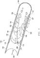
- a side perspective cross-sectional view of an embodiment of a multiphase vortex flowmeter 100 is shown.
- a fluid 130 is shown passing through a channel 180 of the flowmeter 100 defined by a cylindrical housing 190.
- the fluid 130 is flowing in a direction indicated by an arrow 185 and intersects a bluff body 175 at a face 177 thereof.
- discrete vortices 135 may emerge at a detectable frequency.
- the frequency of the emergence of these vortices may be detected by one or more differential pressure sensors 150, 350 to ascertain a rate of flow for the fluid 130. The higher the frequency/rate of vortex formation, the faster the flow.
- the flowmeter 100 is also outfitted with more downstream supplemental sensor assemblies 110, 112.
- assemblies 110, 112 may be provided to help ascertain a flowrate of the fluid 130 when vortex formation is compromised.
- a fluid 130 changes phases, such as from a predominantly liquid oil to a hydrocarbon gas or water, it may fail to present discernable vortices 135.
- more random disturbances or perturbations 230 may emerge for a period of time.
- these perturbations may emerge in response to fluid encountering the bluff body 175 but may occur at no particularly reliable frequency from which to ascertain flow rate from a single sensor location at the bluff body 175.
- the supplemental sensor assemblies 110, 112 which continue more downstream, are provided so as to prevent any substantial interruption in the acquisition of flowrate information.
- these sensor assemblies 110, 112 are referred to as 'supplemental' in the embodiment shown.
- these assemblies 110, 112 are primary in nature, providing flow information from vortex detections 135 as well, perhaps in complete absence of the sensors right at the bluff body 175 (e.g. 150).
- the supplemental sensor assemblies 110, 112 include two separate detection locations or zones 120, 125 that are spaced apart by a known distance (d).
- the flowmeter 100 may be no more than a few inches in length with the distance (d) being less than one inch.
- sensors 122, 127 capable of detecting a perturbation 230 are positioned at each zone 120, 125 (see Figs. 3B and 3C ).
- Such sensors 122 may be temperature sensors, pressure sensors, acoustic sensors, ultrasonic, piezo-patches or others, likely operable at up to several hundred Hertz and capable of detecting a fluid characteristic of a perturbation 230 (and/or a vortex 135), whereas sensor 127 is a piezo patch sensor.
- sensor 127 is a piezo patch sensor.
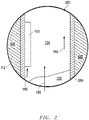
- FIG. 2 an enlarged view of a section of a well 280 taken from 2-2 of Fig. 4 is shown.
- the flowmeter 100 of Fig. 1 can be seen accommodated within the well 280. More specifically, the flowmeter 100 is shown secured to a casing 285 defining the well 280 as it traverses a formation 495. In this way, the flowmeter 100 may be utilized to ascertain fluid flow (see arrows 185). Indeed, as detailed further below, even as the fluid changes from one phase (130) to another (230), flowrate detections may continue in an uninterrupted fashion as alluded to above.
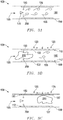
- FIG. 3A-3C side cross-sectional schematic views of the flowmeter 100 of Fig. 1 are shown as fluid vortices 135 give way to disruptive perturbations 230 as phase changes occur.
- a period of transition from one fluid type to another may occur such as liquid hydrocarbons (130) giving way to a mixture (230) with hydrocarbon gas and eventually gas alone (430). Nevertheless, as detailed herein, uninterrupted flowrate measurements may continue in spite of the phase change and perturbations (e.g. 230).
- vortices 135 are shown that may present at a detectable frequency that is indicative of flowrate. As noted above, this is to be expected where the fluid flowing through the channel 180 is of a consistent phase, such as where a particular liquid is present without any substantial gas or other liquid type mixed therewith. Indeed, with such a uniform fluid present, pressure sensors 150, 350 at a single location adjacent the bluff body 175 may be sufficient to detect the frequency of the vortex formation so as to ascertain flowrate in a direct, linear fashion. As indicated, the sensors 150, 350 are located adjacent the bluff body 175 given that this is the source of vortex formation. Thus, a substantially direct and accurate measurement is available without concern over drift or other similar issues.
- the sensors 150, 350 may also be positioned at other locations within the housing 190 downstream of the bluff body 175. Indeed, along these lines, in the embodiment shown, the flowmeter 100 does include additional or "supplemental" sensing capacity to address circumstances when fluid flow continues but without a regular frequency presentation of vortices 135.
- the flowmeter 100 of Fig. 3A is depicted as the fluid type within the channel 180 begins to change.
- additional detection zones 120, 125 with supplemental sensors 122, 127 may come into play.
- the interaction of the fluid with the bluff body 175 of Fig. 3A may cease to present vortices 135 at discernable frequencies (see Fig. 3A ).
- the interaction of the transitioning fluid with the bluff body 175 may result in the emergence of detectable perturbations 230.
- the perturbation 230 may continue to flow (arrow 185) through the channel 180 bypassing an initial detection zone 120.
- this zone 120 is provided by way of sensor assemblies 110, 112 equipped with sensors 122. While perturbations such as the one depicted (230) may not present at clear usable frequencies, individual characteristics of a given perturbation 230 may nevertheless be detectable.
- the sensors 122 in the initial detection zone 120 may be piezo, acoustic, pressure, temperature or other type of sensors as noted above for detecting a characteristic of the perturbation 230.
- the availability of durable cost-effective piezo-patches, in particular, may make these types of sensors desirable.
- an encapsulated, thin walled patch may be used to circumferentially line the housing 190 with openings or exposures provided in the area of a given zone 120 (or 125 as discussed below).
- a single sensor 122 may suffice for the zone 120.
- a sensor 122 is provided that is configured to work as an acoustic receiver for an acoustic signal that is transmitted from the opposite side of the channel 180 (e.g. at the location of the opposite sensor 122). In this scenario, the transmitted signal may be compared to the detection for ascertaining the presence of the perturbation 230 in the initial zone 120.
- a cross-sectional view of the flowmeter 100 of Fig. 3B is shown as the perturbation 230 detected within the initial zone 120 continues along with the flow (185) across a distance (d) and reaches the second zone 125.
- the same perturbation 230 may still be detected again within the second zone 125 via sensors 127.
- this second set of sensors 127 detects the same acoustic perturbation that has been detected in the initial zone 120, the fact that this is the same perturbation 230 may be confirmed.
- the time of flight or the time it takes for the detected perturbation 230 to traverse the known distance (d), allows for the flowrate to be determined.
- flowrate may continue to be ascertained.
- vortex-focused sensors 150, 350 may be pressure sensors that are used to detect a frequency of vortices 135 when present but also utilized to detect pressure of a perturbation 230 in absence of vortices 135.
- the sensors 150, 350 at the bluff body 175 may provide the initial zone of detection for the perturbation 230.
- another zone such as 120 (or 125) may be at a known distance from the bluff body sensors 150, 350 utilizing sensors 122 (or piezo patch sensor 127) to make the second detection of the perturbation 230.
- a time of flight computation may again be made for sake of ascertaining flowrate. As a practical matter, this may reduce number of zones and sensors required to determine flowrate during a fluid transition from one phase to another.
- supplemental sensors 122, 127 at one zone 120 or another 125 may even be employed during periods of reliable vortex shedding where the frequency of vortices 135 is ascertained by sensors 150, 350.
- flowrate detection of a consistent single phase fluid may take place as described above at Fig. 1 .
- supplemental sensors 122 (or piezo patch sensor 127) at a subsequent zone 120 (or 125) may still be employed to provide time of flight information in order to enhance the flowrate analysis under way.
- the flowmeter 100 is shown in a real-world environment where it may be used to provide continuous flowrate information even as fluid therethrough changes from one phase to another.
- an overview depiction of an oilfield 400 is shown with a well 280 accommodating the flowmeter 100 of Fig. 2 .
- fluid flow in the well 280 may be measured on a substantially continuous basis regardless of phase change.
- the wellsite includes equipment 425 in the form of a rig 440 to support initial downhole completions or subsequent interventions. Further, a production line 480 emerges from a wellhead 475 for collection of downhole fluids 130, 230, 430. A control unit 450 adjacent the wellhead 475 may be utilized for a variety of purposes, including analysis of flowrate data from the flowmeter 100.
- the well 280 is outfitted with a casing 285 traversing various formation layers 490, 495.
- a production region 497 with perforations 499 may be targeted for production.
- fluid may flow (see arrow 185) from locations downhole of this region 497 as well.
- fluid in the well 280 includes hydrocarbon liquid 130 that gives way for a time to fluid gas 430, perhaps originating from outside of the targeted production region 497.
- phase change fluid 230 is present between the liquid 130 and gas 430.
- this phase change fluid 230 is the same fluid that makes up the perturbation 230 as depicted in Figs. 3B and 3C referenced above, thus, sharing the same feature numbering.
- flowrate may be continuously determined as all fluid (130, 230, 430) makes its way up the well 280 and is produced at surface.
- flowrate information may be relayed to the control unit 450 where it is analyzed in an uninterrupted fashion regardless of fluid type or phase change conditions. Relaying of the detection information from the flowmeter 100 may be achieved wirelessly, through fiber optics, electrical line or by way of any practical conventional mode for the oilfield environment. Regardless, the information may be attained and analyzed on a substantially continuous basis irrespective of the multiphase nature of the fluids due to the unique features of the flowmeter 100.
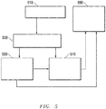
- FIG. 5 a flow-chart summarizing an example not part of the invention of employing a multiphase flowmeter in a well during oilfield operations is depicted.
- flowrate may be monitored on a substantially continuous basis. This involves detecting with a flowmeter fluid characteristics as indicated at 530. When the fluid is in a single, consistent phase and type, this may include monitoring frequency of vortices generated within the flowmeter as indicated at 550. However, even when such detections are not available, such as during a transitional phase for the fluid, time of flight monitoring of perturbations may take place as noted at 570.
- time of flight monitoring of generated vortices may also be utilized where the fluid is not in a transitional phase, either as a supplement to, or replacement for, vortex frequency detections. Regardless, no interruption in flowrate monitoring is required even in the event of fluid phase change.
- Embodiments described hereinabove include vortex flowmeter measurements that are enhanced to account for periods where vortex frequency measurements may be compromised due to the emergence of a fluid phase change.
- the advantages of improved accuracy and range from direct measurements may be retained. More specifically, even where perturbations emerge as a result of multi-phase flowing fluid, as is common for an oilfield well, the ability of the flowmeter to detect transit time of perturbations allows for continued accurate flowrate detection.
Landscapes
- Physics & Mathematics (AREA)
- General Physics & Mathematics (AREA)
- Fluid Mechanics (AREA)
- Life Sciences & Earth Sciences (AREA)
- Engineering & Computer Science (AREA)
- Chemical & Material Sciences (AREA)
- Health & Medical Sciences (AREA)
- Geology (AREA)
- Mining & Mineral Resources (AREA)
- Pathology (AREA)
- Immunology (AREA)
- General Health & Medical Sciences (AREA)
- Biochemistry (AREA)
- Analytical Chemistry (AREA)
- General Chemical & Material Sciences (AREA)
- Oil, Petroleum & Natural Gas (AREA)
- Geophysics (AREA)
- Food Science & Technology (AREA)
- Medicinal Chemistry (AREA)
- Chemical Kinetics & Catalysis (AREA)
- Geochemistry & Mineralogy (AREA)
- General Life Sciences & Earth Sciences (AREA)
- Environmental & Geological Engineering (AREA)
- Acoustics & Sound (AREA)
- Measuring Volume Flow (AREA)
Claims (16)
- Verfahren zur Durchflusserfassung in einem Fluidkanal (180), wobei das Verfahren umfasst:Einbringen eines Prallkörpers (175) in einen Strom von Fluid (130) im Kanal (180), um eines aus einem abgelösten Wirbel (135) und einer Störung (230) des Fluids auszubilden;Erfassen (570) des einen aus dem Wirbel und der Störung an einem ersten Ort (120) im Kanal;Erfassen (570) des einen aus dem Wirbel und der Störung an einem zweiten Ort (125) im Kanal stromabwärts vom ersten Ort; undBerechnen eines Durchflusses für den Strom von Fluid basierend auf einer Zeitdifferenz zwischen den Erfassungen,dadurch gekennzeichnet, dassdas Erfassen (570) der Störung (230) mit einem Sensor (110, 112, 122, 127) ausgeführt wird, bei dem es sich um einen Piezopatch-Sensor handelt.
- Verfahren nach Anspruch 1, wobei es sich bei dem Strom von Fluid (130) um einen Mehrphasenstrom handelt und das Berechnen des Durchflusses ungeachtet der Fluidphase im Wesentlichen kontinuierlich ist.
- Verfahren nach Anspruch 1, ferner umfassend:Generieren einer Häufigkeit von Wirbeln (135) aus dem Strom von Fluid (130) mit dem Prallkörper (175) während einer Periode einer konsistenten Phase des Fluids; undErfassen (550) der Häufigkeit von Wirbeln am Prallkörper, um den Durchfluss im Voraus vor dem Berechnen des Durchflusses basierend auf der Zeitdifferenz zwischen den Erfassungen zu ermitteln.
- Verfahren nach Anspruch 3, ferner umfassend ein Generieren der Störung (230) aus dem Strom von Fluid (130) mit dem Prallkörper (175) während einer Periode des Phasenübergangs des Fluids, um das Berechnen des Durchflusses bei Ausbleiben des Erfassens (550) der Häufigkeit der Wirbel zu unterstützen.
- Verfahren gemäß Anspruch 1, ferner umfassend:Erfassen (550) einer Häufigkeit des Wirbels, um einen Durchfluss des Fluids während der Periode der konsistenten Phase zu ermitteln;Ausbilden einer Störung (230) durch Einbringen des Prallkörpers in den Strom von Fluid während einer Periode des Phasenübergangs des Fluids; undErfassen (570) der Störung an dem um einen bekannten Abstand (d) voneinander entfernten ersten und zweiten Ort (120, 125) im Kanal, um einen Durchfluss für den Strom von Fluid während des Phasenübergangs basierend auf einer Zeitdifferenz zwischen den Erfassungen der Störung zu berechnen.
- Verfahren nach Anspruch 5, wobei sich die Orte (120, 125) im Kanal (180) stromabwärts vom Prallkörper (175) befinden.
- Verfahren nach Anspruch 5, wobei das Erfassen (550) der Häufigkeit der Wirbel mit einem an den Prallkörper (175) angrenzenden Sensor (150, 350) ausgeführt wird.
- Verfahren nach Anspruch 7, wobei das Erfassen (570) der Störung (230) am Ort des an den Prallkörper (175) angrenzenden Sensors (150, 350) und an einem Ort (120, 125) stromabwärts davon erfolgt.
- Verfahren nach Anspruch 5, wobei es sich bei dem Piezosensor um einen ein den Kanal (180) begrenzendes Gehäuse (190) auskleidenden eingekapselten Piezopatch-Sensor mit am ersten und zweiten Ort (120, 125) freiliegenden Abschnitten handelt.
- Mehrphasen-Durchflussmesser (100), umfassend:ein Gehäuse (190) zum Begrenzen eines Kanals (180) zur Aufnahme eines Stroms von Fluid (130) durch denselben;einen Prallkörper (175), der im Kanal befestigt ist, um eines aus einem Wirbel (135) und einer Störung (230) während des Strömens von Fluid durch den Kanal auszubilden;einen ersten Sensor (110, 122) zur Erfassung des einen aus dem Wirbel und der Störung, wobei sich der erste Sensor an einem ersten Ort (120) befindet, bei dem es sich um einen aus einem Ort am Prallkörper und einem Ort stromabwärts vom Prallkörper handelt; und einen zweiten Sensor (112) zur Erfassung des einen aus dem Wirbel und der Störung, wobei sich der zweite Sensor an einem zweiten Ort (125) befindet, der sich in einem bekannten Abstand (d) stromabwärts vom ersten Sensor befindet, um Laufzeitinformationen zwischen den Erfassungen zur Ermittlung des Durchflusses des Stroms von Fluid bereitzustellen,dadurch gekennzeichnet, dasses sich bei dem zweiten Sensor (112, 127) um einen Piezopatch-Sensor handelt.
- Mehrphasen-Durchflussmesser (100) nach Anspruch 10, wobei es sich bei dem Fluid (130) um ein Ölfeldfluid handelt und der Durchflussmesser (100) zur Integrierung in eine permanente Untertageeinrichtung in einer Bohrung (280) ausgelegt ist.
- Mehrphasen-Durchflussmesser (100) nach Anspruch 10, wobei es sich bei dem Fluid (130) um ein Ölfeldfluid handelt und der Durchflussmesser zur Integrierung in ein Bohrlochmessgerät ausgelegt ist.
- Mehrphasen-Durchflussmesser (100) nach Anspruch 10, wobei der Durchflussmesser als fluidischer Oszillator ausgelegt ist.
- Mehrphasen-Durchflussmesser (100) nach Anspruch 10, wobei es sich bei dem Piezosensor um einen ein Inneres des Gehäuses (190) auskleidenden eingekapselten Piezopatch-Sensor mit einem an einer ersten Zone (120) freiliegenden ersten Abschnitt als erstem Sensor (110, 122) und einem an einer zweiten Zone (125) freiliegenden zweiten Abschnitt als zweitem Sensor (112) handelt.
- Mehrphasen-Durchflussmesser (100) nach Anspruch 10, wobei es sich bei dem ersten Sensor (110, 122) um einen ersten Zusatzsensor stromabwärts vom Prallkörper (175) und bei dem zweiten Sensor (112) um einen zweiten Zusatzsensor stromabwärts vom ersten Zusatzsensor handelt, wobei die Zusatzsensoren zum Erfassen der Störung (230) während einer Periode eines Phasenübergangs des Fluids (130) dienen, wobei der Durchflussmesser ferner einen Prallkörpersensor am Prallkörper zum Erfassen einer Häufigkeit von abgelösten Wirbeln (135) während einer Periode einer konsistenten Phase des Fluids umfasst.
- Mehrphasen-Durchflussmesser (100) nach Anspruch 15, wobei es sich bei dem Prallkörpersensor (150, 350) um einen Drucksensor und bei den Zusatzsensoren (110, 112, 122) um eine Piezopatch-Art handelt.
Applications Claiming Priority (1)
| Application Number | Priority Date | Filing Date | Title |
|---|---|---|---|
| EP16290239 | 2016-12-16 |
Publications (2)
| Publication Number | Publication Date |
|---|---|
| EP3343184A1 EP3343184A1 (de) | 2018-07-04 |
| EP3343184B1 true EP3343184B1 (de) | 2020-08-05 |
Family
ID=57755100
Family Applications (1)
| Application Number | Title | Priority Date | Filing Date |
|---|---|---|---|
| EP17199805.7A Active EP3343184B1 (de) | 2016-12-16 | 2017-11-03 | Multiphasiges wirbelströmungsmessgerät |
Country Status (2)
| Country | Link |
|---|---|
| US (1) | US10473501B2 (de) |
| EP (1) | EP3343184B1 (de) |
Families Citing this family (5)
| Publication number | Priority date | Publication date | Assignee | Title |
|---|---|---|---|---|
| US11619534B2 (en) | 2019-04-10 | 2023-04-04 | Honeywell International Inc. | System and method for measuring saturated steam flow using redundant measurements |
| US11773694B2 (en) | 2019-06-25 | 2023-10-03 | Schlumberger Technology Corporation | Power generation for multi-stage wireless completions |
| CN110501050A (zh) * | 2019-08-29 | 2019-11-26 | 广州敏华仪器仪表有限公司 | 一种污水排放计量计 |
| US12422285B2 (en) | 2021-03-03 | 2025-09-23 | Halker Smart Solutions LLC | Multiphase vortex flowmeter system |
| US12455181B2 (en) * | 2023-04-24 | 2025-10-28 | Saudi Arabian Oil Company | Measurement of bulk flow velocity and mixture sound speed using an array of dynamic pressure sensors |
Family Cites Families (8)
| Publication number | Priority date | Publication date | Assignee | Title |
|---|---|---|---|---|
| GB9823675D0 (en) | 1998-10-30 | 1998-12-23 | Schlumberger Ltd | Flowmeter |
| US8346491B2 (en) * | 2007-02-23 | 2013-01-01 | Expro Meters, Inc. | Sonar-based flow meter operable to provide product identification |
| DE102009001526A1 (de) * | 2009-03-12 | 2010-09-16 | Endress + Hauser Flowtec Ag | Wirbelströmungsmessgerät zum Überwachen und/oder Messen einer verteilten Teilchen- und/oder Tröpfchen-Strömung |
| CN101699225B (zh) | 2009-10-26 | 2012-04-25 | 山东聊城科尔仪表科技有限公司 | 一种涡街流量传感测量方法及专用传感器 |
| DE102013110243A1 (de) * | 2013-09-17 | 2015-04-02 | Endress + Hauser Flowtec Ag | Verfahren zur Überwachung eines Messgerätes der Automatisierungstechnik |
| US9404781B2 (en) * | 2014-04-01 | 2016-08-02 | Saudi Arabian Oil Company | Multiphase metering with ultrasonic tomography and vortex shedding |
| WO2016176224A1 (en) * | 2015-04-27 | 2016-11-03 | Kim Lewis | Fluid flow meter diagnostics |
| US10704939B2 (en) * | 2015-07-28 | 2020-07-07 | Expro Meters, Inc. | Methodology and apparatus for distinguishing single phase fluid flows from multiphase fluid flows using a flow meter |
-
2017
- 2017-11-03 EP EP17199805.7A patent/EP3343184B1/de active Active
- 2017-11-03 US US15/802,491 patent/US10473501B2/en active Active
Non-Patent Citations (1)
| Title |
|---|
| None * |
Also Published As
| Publication number | Publication date |
|---|---|
| US20180172495A1 (en) | 2018-06-21 |
| US10473501B2 (en) | 2019-11-12 |
| EP3343184A1 (de) | 2018-07-04 |
Similar Documents
| Publication | Publication Date | Title |
|---|---|---|
| EP3343184B1 (de) | Multiphasiges wirbelströmungsmessgerät | |
| US5551287A (en) | Method of monitoring fluids entering a wellbore | |
| US8061219B2 (en) | Flow restriction insert for differential pressure measurement | |
| US10240455B2 (en) | Method and system for monitoring fluid flow in a conduit | |
| US20190120048A1 (en) | Using fluidic devices to estimate water cut in production fluids | |
| US10036242B2 (en) | Downhole acoustic density detection | |
| EP3494278B1 (de) | Überwachung eines kohlenwasserstoffflüssigkeitsflusses | |
| US20150211362A1 (en) | Systems and methods for monitoring drilling fluid conditions | |
| US20120279292A1 (en) | Flow measurements in an oil reservoir | |
| EP3280875B1 (de) | Instrument zur strömungsüberwachung | |
| US20230392460A1 (en) | Smart system for early kick and loss detection during drilling operations | |
| US20160097273A1 (en) | Multi-phase fluid flow profile measurement | |
| EP1078228B1 (de) | Durchflussmesser | |
| US11603733B2 (en) | Wellbore flow monitoring using a partially dissolvable plug | |
| CA2924895A1 (en) | Determining well fluid flow velocity based on vortex frequency | |
| US9523274B2 (en) | Telemetry system and method of communicating through a tubular |
Legal Events
| Date | Code | Title | Description |
|---|---|---|---|
| PUAI | Public reference made under article 153(3) epc to a published international application that has entered the european phase |
Free format text: ORIGINAL CODE: 0009012 |
|
| STAA | Information on the status of an ep patent application or granted ep patent |
Free format text: STATUS: THE APPLICATION HAS BEEN PUBLISHED |
|
| AK | Designated contracting states |
Kind code of ref document: A1 Designated state(s): AL AT BE BG CH CY CZ DE DK EE ES FI FR GB GR HR HU IE IS IT LI LT LU LV MC MK MT NL NO PL PT RO RS SE SI SK SM TR |
|
| AX | Request for extension of the european patent |
Extension state: BA ME |
|
| STAA | Information on the status of an ep patent application or granted ep patent |
Free format text: STATUS: REQUEST FOR EXAMINATION WAS MADE |
|
| 17P | Request for examination filed |
Effective date: 20181231 |
|
| RBV | Designated contracting states (corrected) |
Designated state(s): AL AT BE BG CH CY CZ DE DK EE ES FI FR GB GR HR HU IE IS IT LI LT LU LV MC MK MT NL NO PL PT RO RS SE SI SK SM TR |
|
| STAA | Information on the status of an ep patent application or granted ep patent |
Free format text: STATUS: EXAMINATION IS IN PROGRESS |
|
| 17Q | First examination report despatched |
Effective date: 20190531 |
|
| GRAP | Despatch of communication of intention to grant a patent |
Free format text: ORIGINAL CODE: EPIDOSNIGR1 |
|
| RIC1 | Information provided on ipc code assigned before grant |
Ipc: G01N 33/28 20060101ALI20200129BHEP Ipc: G01F 1/708 20060101ALI20200129BHEP Ipc: G01F 5/00 20060101ALI20200129BHEP Ipc: G01F 1/32 20060101AFI20200129BHEP Ipc: G01F 1/712 20060101ALI20200129BHEP Ipc: E21B 47/10 20120101ALI20200129BHEP Ipc: G01F 7/00 20060101ALI20200129BHEP |
|
| STAA | Information on the status of an ep patent application or granted ep patent |
Free format text: STATUS: GRANT OF PATENT IS INTENDED |
|
| INTG | Intention to grant announced |
Effective date: 20200305 |
|
| GRAS | Grant fee paid |
Free format text: ORIGINAL CODE: EPIDOSNIGR3 |
|
| GRAA | (expected) grant |
Free format text: ORIGINAL CODE: 0009210 |
|
| STAA | Information on the status of an ep patent application or granted ep patent |
Free format text: STATUS: THE PATENT HAS BEEN GRANTED |
|
| AK | Designated contracting states |
Kind code of ref document: B1 Designated state(s): AL AT BE BG CH CY CZ DE DK EE ES FI FR GB GR HR HU IE IS IT LI LT LU LV MC MK MT NL NO PL PT RO RS SE SI SK SM TR |
|
| REG | Reference to a national code |
Ref country code: GB Ref legal event code: FG4D |
|
| REG | Reference to a national code |
Ref country code: CH Ref legal event code: EP |
|
| REG | Reference to a national code |
Ref country code: AT Ref legal event code: REF Ref document number: 1299343 Country of ref document: AT Kind code of ref document: T Effective date: 20200815 |
|
| REG | Reference to a national code |
Ref country code: DE Ref legal event code: R096 Ref document number: 602017020945 Country of ref document: DE |
|
| REG | Reference to a national code |
Ref country code: IE Ref legal event code: FG4D |
|
| REG | Reference to a national code |
Ref country code: NO Ref legal event code: T2 Effective date: 20200805 |
|
| REG | Reference to a national code |
Ref country code: LT Ref legal event code: MG4D |
|
| REG | Reference to a national code |
Ref country code: NL Ref legal event code: MP Effective date: 20200805 |
|
| REG | Reference to a national code |
Ref country code: AT Ref legal event code: MK05 Ref document number: 1299343 Country of ref document: AT Kind code of ref document: T Effective date: 20200805 |
|
| PG25 | Lapsed in a contracting state [announced via postgrant information from national office to epo] |
Ref country code: HR Free format text: LAPSE BECAUSE OF FAILURE TO SUBMIT A TRANSLATION OF THE DESCRIPTION OR TO PAY THE FEE WITHIN THE PRESCRIBED TIME-LIMIT Effective date: 20200805 Ref country code: LT Free format text: LAPSE BECAUSE OF FAILURE TO SUBMIT A TRANSLATION OF THE DESCRIPTION OR TO PAY THE FEE WITHIN THE PRESCRIBED TIME-LIMIT Effective date: 20200805 Ref country code: AT Free format text: LAPSE BECAUSE OF FAILURE TO SUBMIT A TRANSLATION OF THE DESCRIPTION OR TO PAY THE FEE WITHIN THE PRESCRIBED TIME-LIMIT Effective date: 20200805 Ref country code: FI Free format text: LAPSE BECAUSE OF FAILURE TO SUBMIT A TRANSLATION OF THE DESCRIPTION OR TO PAY THE FEE WITHIN THE PRESCRIBED TIME-LIMIT Effective date: 20200805 Ref country code: GR Free format text: LAPSE BECAUSE OF FAILURE TO SUBMIT A TRANSLATION OF THE DESCRIPTION OR TO PAY THE FEE WITHIN THE PRESCRIBED TIME-LIMIT Effective date: 20201106 Ref country code: SE Free format text: LAPSE BECAUSE OF FAILURE TO SUBMIT A TRANSLATION OF THE DESCRIPTION OR TO PAY THE FEE WITHIN THE PRESCRIBED TIME-LIMIT Effective date: 20200805 Ref country code: PT Free format text: LAPSE BECAUSE OF FAILURE TO SUBMIT A TRANSLATION OF THE DESCRIPTION OR TO PAY THE FEE WITHIN THE PRESCRIBED TIME-LIMIT Effective date: 20201207 Ref country code: ES Free format text: LAPSE BECAUSE OF FAILURE TO SUBMIT A TRANSLATION OF THE DESCRIPTION OR TO PAY THE FEE WITHIN THE PRESCRIBED TIME-LIMIT Effective date: 20200805 Ref country code: BG Free format text: LAPSE BECAUSE OF FAILURE TO SUBMIT A TRANSLATION OF THE DESCRIPTION OR TO PAY THE FEE WITHIN THE PRESCRIBED TIME-LIMIT Effective date: 20201105 |
|
| PG25 | Lapsed in a contracting state [announced via postgrant information from national office to epo] |
Ref country code: NL Free format text: LAPSE BECAUSE OF FAILURE TO SUBMIT A TRANSLATION OF THE DESCRIPTION OR TO PAY THE FEE WITHIN THE PRESCRIBED TIME-LIMIT Effective date: 20200805 Ref country code: PL Free format text: LAPSE BECAUSE OF FAILURE TO SUBMIT A TRANSLATION OF THE DESCRIPTION OR TO PAY THE FEE WITHIN THE PRESCRIBED TIME-LIMIT Effective date: 20200805 Ref country code: LV Free format text: LAPSE BECAUSE OF FAILURE TO SUBMIT A TRANSLATION OF THE DESCRIPTION OR TO PAY THE FEE WITHIN THE PRESCRIBED TIME-LIMIT Effective date: 20200805 Ref country code: RS Free format text: LAPSE BECAUSE OF FAILURE TO SUBMIT A TRANSLATION OF THE DESCRIPTION OR TO PAY THE FEE WITHIN THE PRESCRIBED TIME-LIMIT Effective date: 20200805 Ref country code: IS Free format text: LAPSE BECAUSE OF FAILURE TO SUBMIT A TRANSLATION OF THE DESCRIPTION OR TO PAY THE FEE WITHIN THE PRESCRIBED TIME-LIMIT Effective date: 20201205 |
|
| PG25 | Lapsed in a contracting state [announced via postgrant information from national office to epo] |
Ref country code: EE Free format text: LAPSE BECAUSE OF FAILURE TO SUBMIT A TRANSLATION OF THE DESCRIPTION OR TO PAY THE FEE WITHIN THE PRESCRIBED TIME-LIMIT Effective date: 20200805 Ref country code: SM Free format text: LAPSE BECAUSE OF FAILURE TO SUBMIT A TRANSLATION OF THE DESCRIPTION OR TO PAY THE FEE WITHIN THE PRESCRIBED TIME-LIMIT Effective date: 20200805 Ref country code: CZ Free format text: LAPSE BECAUSE OF FAILURE TO SUBMIT A TRANSLATION OF THE DESCRIPTION OR TO PAY THE FEE WITHIN THE PRESCRIBED TIME-LIMIT Effective date: 20200805 Ref country code: DK Free format text: LAPSE BECAUSE OF FAILURE TO SUBMIT A TRANSLATION OF THE DESCRIPTION OR TO PAY THE FEE WITHIN THE PRESCRIBED TIME-LIMIT Effective date: 20200805 Ref country code: RO Free format text: LAPSE BECAUSE OF FAILURE TO SUBMIT A TRANSLATION OF THE DESCRIPTION OR TO PAY THE FEE WITHIN THE PRESCRIBED TIME-LIMIT Effective date: 20200805 |
|
| REG | Reference to a national code |
Ref country code: DE Ref legal event code: R097 Ref document number: 602017020945 Country of ref document: DE |
|
| PG25 | Lapsed in a contracting state [announced via postgrant information from national office to epo] |
Ref country code: AL Free format text: LAPSE BECAUSE OF FAILURE TO SUBMIT A TRANSLATION OF THE DESCRIPTION OR TO PAY THE FEE WITHIN THE PRESCRIBED TIME-LIMIT Effective date: 20200805 |
|
| REG | Reference to a national code |
Ref country code: DE Ref legal event code: R119 Ref document number: 602017020945 Country of ref document: DE |
|
| PLBE | No opposition filed within time limit |
Free format text: ORIGINAL CODE: 0009261 |
|
| STAA | Information on the status of an ep patent application or granted ep patent |
Free format text: STATUS: NO OPPOSITION FILED WITHIN TIME LIMIT |
|
| PG25 | Lapsed in a contracting state [announced via postgrant information from national office to epo] |
Ref country code: SK Free format text: LAPSE BECAUSE OF FAILURE TO SUBMIT A TRANSLATION OF THE DESCRIPTION OR TO PAY THE FEE WITHIN THE PRESCRIBED TIME-LIMIT Effective date: 20200805 Ref country code: MC Free format text: LAPSE BECAUSE OF FAILURE TO SUBMIT A TRANSLATION OF THE DESCRIPTION OR TO PAY THE FEE WITHIN THE PRESCRIBED TIME-LIMIT Effective date: 20200805 |
|
| REG | Reference to a national code |
Ref country code: CH Ref legal event code: PL |
|
| 26N | No opposition filed |
Effective date: 20210507 |
|
| PG25 | Lapsed in a contracting state [announced via postgrant information from national office to epo] |
Ref country code: IT Free format text: LAPSE BECAUSE OF FAILURE TO SUBMIT A TRANSLATION OF THE DESCRIPTION OR TO PAY THE FEE WITHIN THE PRESCRIBED TIME-LIMIT Effective date: 20200805 Ref country code: LU Free format text: LAPSE BECAUSE OF NON-PAYMENT OF DUE FEES Effective date: 20201103 |
|
| REG | Reference to a national code |
Ref country code: BE Ref legal event code: MM Effective date: 20201130 |
|
| PG25 | Lapsed in a contracting state [announced via postgrant information from national office to epo] |
Ref country code: CH Free format text: LAPSE BECAUSE OF NON-PAYMENT OF DUE FEES Effective date: 20201130 Ref country code: SI Free format text: LAPSE BECAUSE OF FAILURE TO SUBMIT A TRANSLATION OF THE DESCRIPTION OR TO PAY THE FEE WITHIN THE PRESCRIBED TIME-LIMIT Effective date: 20200805 Ref country code: LI Free format text: LAPSE BECAUSE OF NON-PAYMENT OF DUE FEES Effective date: 20201130 |
|
| PG25 | Lapsed in a contracting state [announced via postgrant information from national office to epo] |
Ref country code: FR Free format text: LAPSE BECAUSE OF NON-PAYMENT OF DUE FEES Effective date: 20201130 Ref country code: IE Free format text: LAPSE BECAUSE OF NON-PAYMENT OF DUE FEES Effective date: 20201103 |
|
| PG25 | Lapsed in a contracting state [announced via postgrant information from national office to epo] |
Ref country code: DE Free format text: LAPSE BECAUSE OF NON-PAYMENT OF DUE FEES Effective date: 20210601 |
|
| PG25 | Lapsed in a contracting state [announced via postgrant information from national office to epo] |
Ref country code: TR Free format text: LAPSE BECAUSE OF FAILURE TO SUBMIT A TRANSLATION OF THE DESCRIPTION OR TO PAY THE FEE WITHIN THE PRESCRIBED TIME-LIMIT Effective date: 20200805 Ref country code: MT Free format text: LAPSE BECAUSE OF FAILURE TO SUBMIT A TRANSLATION OF THE DESCRIPTION OR TO PAY THE FEE WITHIN THE PRESCRIBED TIME-LIMIT Effective date: 20200805 Ref country code: CY Free format text: LAPSE BECAUSE OF FAILURE TO SUBMIT A TRANSLATION OF THE DESCRIPTION OR TO PAY THE FEE WITHIN THE PRESCRIBED TIME-LIMIT Effective date: 20200805 |
|
| PG25 | Lapsed in a contracting state [announced via postgrant information from national office to epo] |
Ref country code: MK Free format text: LAPSE BECAUSE OF FAILURE TO SUBMIT A TRANSLATION OF THE DESCRIPTION OR TO PAY THE FEE WITHIN THE PRESCRIBED TIME-LIMIT Effective date: 20200805 |
|
| PG25 | Lapsed in a contracting state [announced via postgrant information from national office to epo] |
Ref country code: BE Free format text: LAPSE BECAUSE OF NON-PAYMENT OF DUE FEES Effective date: 20201130 |
|
| P01 | Opt-out of the competence of the unified patent court (upc) registered |
Effective date: 20231208 |
|
| PGFP | Annual fee paid to national office [announced via postgrant information from national office to epo] |
Ref country code: GB Payment date: 20250911 Year of fee payment: 9 |
|
| PGFP | Annual fee paid to national office [announced via postgrant information from national office to epo] |
Ref country code: NO Payment date: 20251113 Year of fee payment: 9 |