EP3343251A1 - Bildgebungsverfahren und lichtregulierungswerkzeug - Google Patents
Bildgebungsverfahren und lichtregulierungswerkzeug Download PDFInfo
- Publication number
- EP3343251A1 EP3343251A1 EP16841187.4A EP16841187A EP3343251A1 EP 3343251 A1 EP3343251 A1 EP 3343251A1 EP 16841187 A EP16841187 A EP 16841187A EP 3343251 A1 EP3343251 A1 EP 3343251A1
- Authority
- EP
- European Patent Office
- Prior art keywords
- light
- principal surface
- regulation device
- holes
- imaging
- Prior art date
- Legal status (The legal status is an assumption and is not a legal conclusion. Google has not performed a legal analysis and makes no representation as to the accuracy of the status listed.)
- Granted
Links
Images





Classifications
-
- G—PHYSICS
- G01—MEASURING; TESTING
- G01N—INVESTIGATING OR ANALYSING MATERIALS BY DETERMINING THEIR CHEMICAL OR PHYSICAL PROPERTIES
- G01N21/00—Investigating or analysing materials by the use of optical means, i.e. using sub-millimetre waves, infrared, visible or ultraviolet light
- G01N21/17—Systems in which incident light is modified in accordance with the properties of the material investigated
-
- G—PHYSICS
- G01—MEASURING; TESTING
- G01N—INVESTIGATING OR ANALYSING MATERIALS BY DETERMINING THEIR CHEMICAL OR PHYSICAL PROPERTIES
- G01N15/00—Investigating characteristics of particles; Investigating permeability, pore-volume or surface-area of porous materials
- G01N15/02—Investigating particle size or size distribution
- G01N15/0205—Investigating particle size or size distribution by optical means
- G01N15/0227—Investigating particle size or size distribution by optical means using imaging; using holography
-
- G—PHYSICS
- G01—MEASURING; TESTING
- G01N—INVESTIGATING OR ANALYSING MATERIALS BY DETERMINING THEIR CHEMICAL OR PHYSICAL PROPERTIES
- G01N15/00—Investigating characteristics of particles; Investigating permeability, pore-volume or surface-area of porous materials
- G01N15/10—Investigating individual particles
- G01N15/14—Optical investigation techniques, e.g. flow cytometry
- G01N15/1429—Signal processing
- G01N15/1433—Signal processing using image recognition
-
- G—PHYSICS
- G01—MEASURING; TESTING
- G01N—INVESTIGATING OR ANALYSING MATERIALS BY DETERMINING THEIR CHEMICAL OR PHYSICAL PROPERTIES
- G01N15/00—Investigating characteristics of particles; Investigating permeability, pore-volume or surface-area of porous materials
- G01N15/10—Investigating individual particles
- G01N15/14—Optical investigation techniques, e.g. flow cytometry
- G01N15/1434—Optical arrangements
-
- G—PHYSICS
- G01—MEASURING; TESTING
- G01N—INVESTIGATING OR ANALYSING MATERIALS BY DETERMINING THEIR CHEMICAL OR PHYSICAL PROPERTIES
- G01N21/00—Investigating or analysing materials by the use of optical means, i.e. using sub-millimetre waves, infrared, visible or ultraviolet light
- G01N21/17—Systems in which incident light is modified in accordance with the properties of the material investigated
- G01N21/25—Colour; Spectral properties, i.e. comparison of effect of material on the light at two or more different wavelengths or wavelength bands
- G01N21/251—Colorimeters; Construction thereof
- G01N21/253—Colorimeters; Construction thereof for batch operation, i.e. multisample apparatus
-
- G—PHYSICS
- G01—MEASURING; TESTING
- G01N—INVESTIGATING OR ANALYSING MATERIALS BY DETERMINING THEIR CHEMICAL OR PHYSICAL PROPERTIES
- G01N21/00—Investigating or analysing materials by the use of optical means, i.e. using sub-millimetre waves, infrared, visible or ultraviolet light
- G01N21/17—Systems in which incident light is modified in accordance with the properties of the material investigated
- G01N21/41—Refractivity; Phase-affecting properties, e.g. optical path length
-
- G—PHYSICS
- G02—OPTICS
- G02B—OPTICAL ELEMENTS, SYSTEMS OR APPARATUS
- G02B21/00—Microscopes
- G02B21/06—Means for illuminating specimens
-
- G—PHYSICS
- G02—OPTICS
- G02B—OPTICAL ELEMENTS, SYSTEMS OR APPARATUS
- G02B21/00—Microscopes
- G02B21/06—Means for illuminating specimens
- G02B21/08—Condensers
- G02B21/082—Condensers for incident illumination only
- G02B21/084—Condensers for incident illumination only having annular illumination around the objective
-
- G—PHYSICS
- G02—OPTICS
- G02B—OPTICAL ELEMENTS, SYSTEMS OR APPARATUS
- G02B27/00—Optical systems or apparatus not provided for by any of the groups G02B1/00 - G02B26/00, G02B30/00
- G02B27/30—Collimators
-
- G—PHYSICS
- G02—OPTICS
- G02B—OPTICAL ELEMENTS, SYSTEMS OR APPARATUS
- G02B5/00—Optical elements other than lenses
-
- G—PHYSICS
- G02—OPTICS
- G02B—OPTICAL ELEMENTS, SYSTEMS OR APPARATUS
- G02B5/00—Optical elements other than lenses
- G02B5/003—Light absorbing elements
-
- G—PHYSICS
- G02—OPTICS
- G02B—OPTICAL ELEMENTS, SYSTEMS OR APPARATUS
- G02B5/00—Optical elements other than lenses
- G02B5/02—Diffusing elements; Afocal elements
- G02B5/0273—Diffusing elements; Afocal elements characterized by the use
- G02B5/0284—Diffusing elements; Afocal elements characterized by the use used in reflection
-
- G—PHYSICS
- G01—MEASURING; TESTING
- G01N—INVESTIGATING OR ANALYSING MATERIALS BY DETERMINING THEIR CHEMICAL OR PHYSICAL PROPERTIES
- G01N15/00—Investigating characteristics of particles; Investigating permeability, pore-volume or surface-area of porous materials
- G01N15/10—Investigating individual particles
- G01N2015/1006—Investigating individual particles for cytology
-
- G—PHYSICS
- G01—MEASURING; TESTING
- G01N—INVESTIGATING OR ANALYSING MATERIALS BY DETERMINING THEIR CHEMICAL OR PHYSICAL PROPERTIES
- G01N15/00—Investigating characteristics of particles; Investigating permeability, pore-volume or surface-area of porous materials
- G01N15/10—Investigating individual particles
- G01N15/14—Optical investigation techniques, e.g. flow cytometry
- G01N2015/1493—Particle size
-
- G—PHYSICS
- G01—MEASURING; TESTING
- G01N—INVESTIGATING OR ANALYSING MATERIALS BY DETERMINING THEIR CHEMICAL OR PHYSICAL PROPERTIES
- G01N2201/00—Features of devices classified in G01N21/00
- G01N2201/06—Illumination; Optics
- G01N2201/061—Sources
Definitions
- This invention relates to a technology for imaging biological specimens carried in a specimen container under illumination and particularly to a technology for adjusting that illumination light.
- Imaging objects included in biological specimens may be, for example, cells or cell colonies two-dimensionally spreading along the bottom surface of a container.
- the cells are close to transparent, sufficient contrast may not be obtained under illumination by diffused light.
- contrast can be improved by performing imaging under illumination by parallel light.
- This invention was developed in view of the above problem and provides a technology enabling imaging to be more conveniently performed under parallel light illumination without requiring an imaging apparatus to have a function of generating parallel light.
- One aspect of the invention is directed to an imaging method which comprises: supporting horizontally a specimen container carrying biological specimens; arranging an illumination light source above the specimen container, a light regulation device between the illumination light source and the specimen container and an imager below the specimen container; and imaging the biological specimens by causing light from the illumination light source to be incident on the biological specimens via the light regulation device and receiving light transmitted downward from the specimen container by the imager, wherein: the light regulation device includes a plate member in a form of a flat plate placeable on the specimen container; a plurality of through holes penetrating from one principal surface side to another principal surface side of the plate member are two-dimensionally and proximately arranged along the one principal surface of the plate member; each through hole is a light-guiding path having a uniform cross-sectional shape along a normal direction to the one principal surface; and a side wall surface of each through hole has a light absorbing property.
- components having a relatively large incident angle, out of the light incident on the one principal surface side of the light regulation device, are absorbed by the light regulation device and light close to parallel light having a traveling direction regulated is emitted from the another principal surface side of the light regulation device.
- illumination light converted into substantially parallel light by the light regulation device is incident on the biological specimens carried in the specimen container. Therefore, the biological specimens such as cells two-dimensionally distributed in the specimen container can be imaged with good contrast.
- the illumination light source may be, for example, a general diffused light source and the illumination light source and the imager need not be modified. Thus, an increase of imaging cost can be suppressed and an imaging failure caused by improper illumination can also be avoided.
- another aspect of this invention is directed to a light regulation device with a plate member having a flat plate shape and including a plurality of through holes penetrating from one principal surface side to another principal surface side and two-dimensionally and proximately arranged along the one principal surface and a frame which covers end surfaces of the plate member, the end surfaces being different from the one principal surface and the another principal surface, wherein each through hole is a light-guiding path having a uniform cross-sectional shape along a normal direction to the one principal surface, and a side wall surface of the through hole has a light absorbing property.
- another aspect of this invention is directed to a light regulation device with a plate member having a flat plate shape and including a plurality of through holes penetrating from one principal surface side to another principal surface side and two-dimensionally and proximately arranged along the one principal surface and a transparent cover member which covers at least one of the one principal surface and the another principal surface, wherein each through hole is a light-guiding path having a uniform cross-sectional shape along a normal direction to the one principal surface, and a side wall surface of the through hole has a light absorbing property.
- These light regulation devices are configured to be applicable to the imaging method described above. Specifically, by arranging the light regulation device configured as described above between the illumination light source and the specimen container, biological specimens can be imaged under parallel light illumination without changing existing imaging apparatus and specimen container at all.
- the plate member in the configuration including the frame for covering the end surfaces of the plate member, the plate member can be mechanically protected by the frame.
- a member having a low strength can be used as the plate member.
- the plate member in the configuration including the cover member for covering at least the another principal surface side of the plate member, the plate member can be protected from damage and dust without impairing optical effects exhibited by the plate member. This makes the light regulation device easily handled.
- illumination light having a direction of emitted light regulated is obtained by using a light regulation device.
- imaging can be conveniently performed under parallel light illumination without requiring an imaging apparatus to have a function of generating parallel light.
- FIG.1 is a diagram showing an example of an imaging apparatus to which an embodiment of an imaging method according to the invention is applied.
- the imaging apparatus images a biological specimen such as a cell cultured in liquid poured into recesses called wells W formed on an upper surface of a well plate WP.
- the imaging is performed in state that a regulation plate 2 is placed on the upper surface of the well plate WP, and that is one feature of the invention.
- the XY plane is a horizontal surface.
- the Z axis represents the vertical axis.
- the (+Z) direction represents the vertically upward direction.
- the well plate WP is generally used in the fields of drug discovery and bioscience.
- a plurality of wells W having a substantially circular cross-section and a transparent and flat bottom surface are disposed to the upper surface of a plate having a flat plate shape.
- the number of the wells W on the well plate WP is arbitrary.
- a well plate WP having 96 (12x8 matrix array) wells can be used.
- a diameter and a depth of each well W are typically about several mm.
- the size of a well plate and the number of wells used in this imaging apparatus 1 are arbitrary without being limited to these.
- well plate having 384 wells may be used.
- the imaging apparatus 1 can be applied to image the biological specimen not only in the well plate provided with a multitude of wells but also, in a flat container called a "dish", for example.
- a predetermined amount of liquid as a culture medium M is poured into each well of the well plate WP.
- Cells cultured under predetermined culture conditions in this liquid are imaging objects of this imaging apparatus 1.
- the culture medium M may be added with appropriate reagents or may be gelled after being poured into the wells W in a liquid state.
- this imaging apparatus 1 for example, a cell or the like cultured on an inner bottom surface of the well can be an imaging object as described later. About 50 to 200 microliters of the liquid is generally usually used.
- an isolated cell a cell colony formed by many cells two-dimension ally distributing in the culture medium, a spheroid (cell cluster) formed by cells gathering three-dimensionally in the culture medium or the like can be applied as the biological specimen cultured in the culture medium and to be imaged.
- an imaging biological specimens such as a bacillus or an organic tissue can be performed by using the imaging apparatus 1.
- these imaging objects are generically called a "cell or the like".
- the imaging apparatus 1 includes a holder 11 which holds the well plate WP carrying sample together with the culture medium in each well W.
- the holder 11 holds the well plate WP in a substantially horizontal posture by being held in contact with a peripheral edge part of the lower surface of the well plate WP.
- the imaging apparatus 1 includes an illuminator 12 arranged above the holder 11, an imager 13 arranged below the holder 11 and a controller 14 which includes a CPU 141 controlling the operation of these components.
- the illuminator 12 emits appropriate diffused light (e.g., white light) toward the well plate WP held by the holder 11. More specifically, for example, a combination of a white LED (light emitting diode) as a light source and a diffusion plate may be used as the illuminator 12.
- a light emitting surface on a lower part of the illuminator 12 has a planar size larger than the upper surface of the well plate WP and is provided to entirely cover an area of the upper surface of the well plate WP where the wells W are formed. In such a configuration, the cells or the like in each well W provided in the well plate WP are uniformly illuminated from above by diffused light L1 emitted in various directions from each part of the lower part of the illuminator 12.
- the imager 13 is provided below the well plate WP held by the holder 11.
- an imaging optical system not shown in the figure is arranged at a position right below the well plate WP.
- An optical axis of the imaging optical system extends in a vertical direction (Z direction).
- the imaging of the biological specimen in the well W is performed by the imager 13. Specifically, light emitted from the illuminator 12 and incident on the surface of the culture medium M from above the well W illuminates the cell or the like which is the imaging object. Light transmitted downward from the bottom surface of the well W is incident to a light receiving surface of an imaging element not shown via the imaging optical system. An image of the imaging object is formed on the light receiving surface of the imaging element by the imaging optical system is imaged by the imaging element.
- a CCD sensor or a CMOS sensor can be used as the imaging element. Either a two-dimensional image sensor or a one-dimensional image sensor can be used.
- the imager 13 is capable of moving in the XYZ directions by a mechanism controller 146 provided in the controller 14. Specifically, the mechanism controller 146 moves the imager 13 in the X direction and the Y direction based on a control command from the CPU 141. By doing so, the imager 13 moves relative to the well W in the horizontal direction. Further, focusing is performed by moving the imager 13 in the Z direction. When imaging is performed with the imaging object in a well W, the mechanism controller 146 positions the imager 13 in the horizontal direction such that the optical axis of the imaging optical system coincides with the center of the well W.
- the imaging element of the imager 13 is a one-dimensional image sensor
- a two-dimensional image can be obtained by scanning the imager 13 to an orthogonal direction to a longitudinal direction of the image sensor.
- the image signal output from the imaging device of the imager 13 is send to the controller 14.
- the image signal is input to an AD converter (A/D) 143 provided in the controller 14 and converted into digital image data.
- the CPU 141 performs appropriate image processings based on the received image data.
- the controller 14 further includes an image memory 144 for storing image data and a memory 145 for storing programs to be executed by the CPU 141 and data generated by the CPU 141, but these may be integrated.
- the CPU 141 performs variable calculation processings described later by executing a control program stored in the memory 145.
- the controller 14 is provided with an interface (I/F) 142.
- the interface 142 has a function of performing data exchange with an external apparatus connected via a communication line besides a function of receiving an operation input from a user and presenting information such as processing results to the user.
- the controller 14 may be an exclusive device including above hardware or may be a general-purpose processing device such as a personal computer or a workstation installed with the control program for performing the process described above.
- a general-purpose computer apparatus may be used as the controller 14 of the imaging apparatus 1.
- the imaging apparatus 1 may have just a minimal control function for controlling each components of the imager 13.
- FIGS. 2A, 2B and 2C are views illustrating combinations of an imaging object and an illumination light source.
- FIG. 2A shows a case where the imaging object in the well W is, for example, a spheroid S having a three-dimensional shape in the culture medium M.
- the imaging object in the well W is, for example, a spheroid S having a three-dimensional shape in the culture medium M.
- a wide range of the surface of the spheroid S is effectively illuminated by the incidence of the diffused light L1 emitted from the illumination unit 12.
- L1 diffused light
- FIG. 2B shows a case where the imaging object is cells (or cell colony) C two-dimensionally and thinly spreading in the culture medium M along an inner bottom surface Wb of the well W.
- the imaging object is cells (or cell colony) C two-dimensionally and thinly spreading in the culture medium M along an inner bottom surface Wb of the well W.
- the cells themselves are close to transparent, it is difficult to obtain high contrast.
- a phenomenon in which a direction of emitted light changes due to peripheral edge parts of the cells C acting as if they were lenses is known. Under illumination by diffused light, it is difficult to selectively detect such light.
- illumination light L2 close to parallel light as shown in FIG. 2C is more preferable. Since the illumination light L2 is refracted by the peripheral edge parts of the cells C, the peripheral edge parts of the cells C have a lower luminance than other areas in an imaged image and the contours of the cells C more clearly appear.
- imaging may be performed for the purpose of automatically measuring the sizes or number of cells distributed in the well W at a high speed.
- an image in which contour parts of the cells or the like are expressed at a luminance clearly different from that of surrounding background parts is useful.
- the illumination means needs to be used according to an imaging object and the purpose of imaging.
- the imaging apparatus 1 is desirably such that illumination light to be emitted from the illumination unit 12 can be switched between diffused light and parallel light according to the imaging object.
- it leads to the enlargement/complication of the apparatus configuration and causes an increase of imaging cost to provide two types of light sources in the imaging apparatus 1 or provide a mechanism for generating parallel light from diffused light in a pseudo manner.
- a failure unable to obtain desired image quality may be possibly caused.
- the illumination unit 12 for emitting diffused light is provided in the imaging apparatus 1.
- a regulation plate 2 to be described next is placed atop the well plate WP. This causes the illumination light L2, which is substantially parallel light, to be incident on the imaging objects in the wells W.
- the regulation plate 2 has a function of causing light components having an incident angle equal to or smaller than a predetermined angle on the upper surface, out of the diffused light emitted from the illumination unit 12, to pass to a lower surface side and, on the other hand, absorbing light components having an incident angle larger than the predetermined angle to regulate the passage thereof to the lower surface side.
- Substantially parallel light having a traveling direction regulated more specifically having the traveling direction inclined at the predetermined angle or smaller with respect to the imaging direction (Z direction) of the imaging unit 13 is emitted from the lower surface of the regulation plate 2 and incident on each well W.
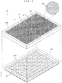
- FIG. 3 is a perspective view showing the structure of the regulation plate.
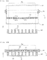
- FIGS. 4A and 4B are side views in section of the regulation plate. More specifically, FIG. 4A is an exploded schematic when a cross-section of the regulation plate 2 is viewed in a section A of FIG. 3 , and FIG. 4B is a sectional view showing a state where the regulation plate 2 is placed on the well plate WP.
- a main part of the regulation plate 2 is a perforated panel 21 having a planar size to entirely cover an area Rw of the upper surface of the well plate WP where the wells W are arranged.
- the perforated panel 21 has a flat plate-like outer shape in which both principal surfaces 21a, 21b are parallel.
- a multitude of through holes 21c penetrating from the side of one principal surface 21a toward the side of the other principal surface 21b perpendicularly to these principal surfaces, i.e. in a direction parallel to normals to these principal surfaces are provided.
- the through holes 21c are arrayed two-dimensionally and regularly in directions along the principal surfaces.
- a partially enlarged view of the one principal surface 21a of the perforated panel 21 is shown in a right-upper circle of FIG. 3 . As shown in this partially enlarged view, each through hole 21c has a hexagonal cross-section and the perforated panel 21 has a so-called honeycomb structure. Such a structure is light in weight and high in strength.
- the one principal surface 21a on an upper side facing the illumination unit 12 when the regulation plate 2 is placed on the well plate WP, out of the both principal surfaces 21a, 21b of the perforated panel 21, is referred to as an "upper surface” and the other principal surface 21b on a lower side facing the upper surface of the well plate WP is referred to as a "lower surface” in some cases.
- the regulation plate 21 itself is structured to be undistinguishable on front and back sides as described below, and functions in the same way even if being turned upside down.
- the perforated panel 21 is housed in a frame 22 having a rectangular outer shape and provided with a rectangular opening, and side surfaces of the perforated panel 21 are protected by the frame 22. Further, cover members 23, 23 formed of a transparent material such as acrylic resin, in the form of thin plates and having the same shape are fitted into the frame 22 to sandwich the perforated panel 21. The upper surface 21a and the lower surface 21b of the perforated panel 21 are protected by being covered by these cover members 23, 23. Note that the cover member may be provided only on either one of the upper surface 21a and the lower surface 21b of the perforated panel 21.
- the upper and lower surfaces 21a, 21b of the perforated panel 21 are protected by the cover members 23, 23 and the side surfaces of the perforated panel 21 are protected by the frame 22. Due to such a structure, the perforated panel 21 itself is not required to have large mechanical strength.
- a honeycomb panel structured by overlapping a multitude of strip-like metal foils e.g. aluminum foils
- partially joining those metal foils and spreading the joined assembly in an overlapping direction can be, for example, used as the perforated panel 21.
- a width of the strip-like metal foils becomes a depth of the through holes 21c
- Honeycomb panels having such a structure come in various sizes and are already commercialized.
- the regulation plate 2 structured by combining the respective members described above is placed on the well plate WP in a horizontal orientation in a state where the upper surface 21a of the perforated panel 21 is facing upward with the lower surface of the lower cover member 23 held in contact with the upper surface of the well plate WP as shown in FIG. 4B .
- an axial direction of each through hole 21c provided in the perforated panel 21 is the vertical direction (Z direction).
- the regulation plate 2 needs to be placed such that the entire area Rw of the upper surface of the well plate WP where the wells W are arranged is covered by the perforated panel 21.
- engaging parts for positioning the regulation plate 2 by being engaged with the well plate WP may be provided between the regulation plate 2 and the well plate WP at least on the lower surface side of the regulation plate 2. It is not necessary to distinguish upper and lower sides of the regulation plate 2 if the engaging parts are provided on both the upper and lower surface sides of the regulation plate 2.
- FIGS. 5A, 5B and 5C are views showing the action of the perforated panel.
- the perforated panel 21 includes the multitude of through holes 21c penetrating from the one principal surface (upper surface) 21a to the other principal surface (lower surface) 21b substantially perpendicularly to the both principal surfaces.
- a cross-sectional shape of each through hole 21c is constant in the axial direction (Z direction) of the through hole from the one principal surface toward the other principal surface. Focusing on the action of the individual through hole 21c, the diffused light L1 having components La, Lb and Lc in various directions is incident on the through hole 21c from the illumination unit 12 arranged to face the upper surface 21a as shown in FIG. 5A .
- the light component La having a small incident angle and incident in parallel to or at a very small angle to the axial direction (Z direction) of the through hole 21c shown by dashed-dotted line propagates straight in the through hole 21c and is emitted downward or substantially downward from an opening on the side of the lower surface 21b.
- the light component Lc having a sufficiently large incident angle is incident on the inner wall surface of the through hole 21c from an opening of the through hole 21c on the side of the upper surface 21a.
- the inner wall surfaces of the through holes 21c are blackened or painted in black in the perforated panel 21.
- the inner wall surfaces of the through holes 21c have a light absorbing property and reflectance on the wall surfaces is very low. Therefore, light incident at a large incident angle on the through hole 21c is absorbed by the inner wall surface and almost no light is emitted from the opening on the side of the lower surface 21b.
- An incident angle ⁇ of the light component Lb inclined most, out of the light components incident on the through hole 21c from the side of the upper surface 21a and emitted from the side of the lower surface 21b without being absorbed by the side wall surface, is dependent on an opening width D and an axial length (i.e. thickness of the perforated panel 21) L of the through hole 21c.
- the light emitted from the lower surface 21b of the perforated panel 21 includes only components whose angle of inclination to the Z direction, which is the axial direction of the through holes 21c, i.e. the vertical direction is equal to or smaller than the above angle ⁇ .
- the regulation plate 2 can illuminate the well plate WP by generating the substantially parallel illumination light L2 from the diffused light L1 irradiated from the illumination unit 12.
- a right side of (Equation 1) represents a round number of an NA (numerical aperture) of an illumination system including the illumination unit 12 and the regulation plate 2.
- NA D / L 2 + D / 2 2 1 / 2 and can be approximately expressed as (D/L) if L»D.
- NA of the emitted light can be controlled by setting the opening width D and axial length L of the through holes 21c.
- examples of using a honeycomb structure for the purpose of controlling a traveling direction of light are conventionally known.
- an illumination range is limited by arranging a device called a "honeycomb grid" on the front surface of an illumination light source.
- a device is for concentrating illumination light emitted at a wide angle in a narrower range.
- inner wall surfaces of through holes are reflective so that light power can be effectively utilized. Therefore, as shown as a comparative example in FIG. 5C , light L3 incident at a relatively large incident angle on an opening on one principal surface side of a through hole G1 of a honeycomb grid G is reflected inside the through hole and emitted from an opening on the other principal surface side.
- the regulation plate 2 for generating substantially parallel light by removing light components not parallel to the imaging direction from the diffused light is different in purpose from such a device.
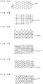
- FIGS. 6A, 6B, 6C, 6D, 6E and 6F are views showing various examples of the cross-sectional shape of the through holes.
- the perforated panel 21 described above is a honeycomb panel and the cross-section and the opening shape of each through hole 21c are hexagonal as shown in FIG. 6A .
- the cross-section needs not be hexagonal, but the through holes 21c having the same shape can be closely arranged by being formed into a hexagonal shape in which facing sides are parallel. Since light incident on the upper surfaces of partition wall parts partitioning between adjacent through holes 21c becomes loss without passing to the lower surface side, partition walls are preferably as thin as possible. Also from this point, a honeycomb structure formed of strip-like foils can be said to be preferable.
- strip-like members may be combined into a lattice, for example, as shown in FIG. 6B and through holes 21d having a rectangular cross-section may be formed. Further, strip-like members may be combined at three different angles as shown in FIG. 6C and through holes 21e having a triangular cross-section may be formed. Further, flat strip-like members and periodically wavy strip-like members may be combined and through holes 21f shaped as shown in FIG. 6D may be formed. Further, periodically wavy strip-like members may be combined in opposite phases and through holes 21g shaped as shown in FIG. 6E may be formed. In this way, perforated panels having through holes having various cross-sectional shapes can be used. The perforated panels having the cross-sectional shapes of the through holes described above are thought to be relatively easily industrially produced.
- a multitude of through holes in which surfaces of the strip-like members serve as side wall surfaces can be realized.
- structures as shown in FIGS. 6A and 6E can be realized.
- a perforated panel structured by perforating a multitude of through holes 21h in a flat plate-like member as shown in FIG. 6F may be employed.
- an interval between adjacent ones of the through holes 21h is desirably as small as possible to suppress light loss.
- a ratio (opening ratio) of an opening area to a surface area of the perforated panel is desirably as close to 100 % as possible.
- the opening width D if the through hole has a circular cross-sectional shape, a diameter of this circle can be set as the opening width D.
- the cross-sectional shape is not circular, a length of a longest line segment drawn in the opening (e.g. diagonal in the case of a rectangular shape) can be regarded as the opening width D that gives a maximum illumination angle of illumination.
- the cross-sectional shape and the cross-sectional size are not the same among the plurality of through holes, the effect of regulating the direction of the illumination light described above can be expected to some extent.
- the cross-sectional shapes and sizes of the respective through holes are more preferably the same to cause the illumination light to be uniformly incident on each part of the wells W.
- FIGS. 7A and 7B are a graph and a diagram for the consideration of a dimensional relationship of the regulation plate. More specifically, FIG. 7A is a graph showing a relationship between the NA of the illumination system and image contrast when thin cells are imaged. Further, FIG. 7B is a diagram showing a preferred dimensional relationship of each part of the regulation plate.
- FIG. 7A is a graph showing a relationship between the NA of the illumination system and image contrast when thin cells are imaged.
- FIG. 7B is a diagram showing a preferred dimensional relationship of each part of the regulation plate.
- FIG. 7B shows a dimensional relationship necessary to obtain a uniform illumination condition in the well W.
- a light quantity distribution of light passing through one through hole 21c has a bell-shaped distribution centered on a center axis (shown by dashed-dotted line) of this through hole 21c.
- Reference sign T denotes a distance from the lower surface 21b of the perforated panel 21 to the well inner bottom surface Wb on which the cells or the like are present. If the regulation plate 2 is placed on the well plate WP, the distance T is equivalent to the sum of a depth of the wells W and a thickness of the cover member 23 on the lower side. In the absence of the cover member on the lower side, the distance T is equal to the depth of the wells W. If this distance T is short or the NA of the illumination system ( ⁇ D/L) is small, the overlap of the light quantity distributions is small between proximate through holes 21c and the uniformity of the illuminance distribution is impaired.
- a distance between the regulation plate 2 and the well plate WP may be adjusted.
- the regulation plate 2 as a small-size, light-weight and portable member without configuring it as a constituent component of the imaging apparatus 1, an image with good image quality can be obtained by adjusting the NA of illumination by a simple configuration.
- FIG. 8 is a table showing an example of effects of the regulation plate.
- the inventor verified differences between images due to the presence or absence of the regulation plate 2 by imaging the same thinly distributing biological specimens such as cells on the inner bottom surface of the well W using the imaging apparatus 1 having a diffused light source as the illumination unit 12.
- two images in an upper row are images obtained by imaging the entire well W, and two images in a lower row are partially enlarged views.
- two images in a left column are images imaged without using the regulation plate 2
- two images in a right column are images imaged with the regulation plate 2 placed on the well plate WP.
- the regulation plate 2 used in an experiment uses a honeycomb panel having a cell size (dimension Sc shown in FIG. 6A ) of 0.7 mm and a thickness of 7 mm as the perforated panel 21.
- imaging is performed with the regulation plate 2 for regulating the direction of passing light arranged between the illumination unit 12 and the well plate WP carrying biological specimens.
- the regulation plate 2 needs not be a constituent component of the imaging apparatus 1 and is configured as a small and light independent member having about the same size as the well plate WP.
- the regulation plate 2 has a function of causing only substantially parallel light components, out of incident diffused light, to selectively pass therethrough. Only by placing the regulation plate 2 on the well plate WP, illumination light close to parallel light for obtaining necessary contrast can be obtained. Thus, imaging can be performed under parallel light illumination by a simple configuration without adding a new configuration to the apparatus.
- the regulation plate 2 is not attached to the imaging apparatus 1 and is carried into and out of the imaging apparatus 1 similarly to the well plate WP. Thus, an imaging failure due to erroneous application of the regulation plate 2 to specimens not requiring the regulation plate 2 is avoided.
- the regulation plate 2 corresponds to a "light regulation device” of the invention and the perforated panel 21 functions as a "plate member” of the invention.
- a space in a hollow part enclosed by the side wall surface of the through hole 21 corresponds to a "light-guiding path” of the invention.
- the frame 22 corresponds to a "frame” of the invention and the cover member 23 corresponds to a “cover member” of the invention.
- the illuminator 12 and the imager 13 respectively function as an "illumination light source” and an “imager” of the invention.
- the well plate WP corresponds to a "specimen container” of the invention.
- the invention is not limited to the above embodiment and various changes other than those described above can be made without departing from the gist of the invention.
- the perforated panel 21 is housed in a space enclosed by the frame 22 and the cover members 23, 23 to protect the perforated panel 21 from breakage, the entrance of dust and the like.
- the frame 22 and the cover members 23 are not necessarily essential components for the function of controlling the illumination.
- the hollow insides of the through holes can be filled with a material transparent to illumination light (e.g. acrylic resin or polycarbonate resin).
- a material transparent to illumination light e.g. acrylic resin or polycarbonate resin.
- the perforated panel itself can have sufficient strength since the through holes become solid, and the either one or both of the frame and the cover members can be omitted.
- the honeycomb panel formed of metal foils is used as the perforated panel 21 in the above embodiment.
- the material of the perforated panel is not limited to this.
- a honeycomb panel formed using paper or aramid resin as a raw material can be used. Even in this case, light reflectance on the surface of the raw material is preferably suppressed to be small, for example, by painting or dyeing in black.
- the regulation plate 2 of the above embodiment is placed atop the well plate WP.
- a spacer member to be sandwiched between the regulation plate 2 and the well plate WP may be separately prepared to adjust a distance from the regulation plate to the well inner bottom surfaces.
- the NA of the illumination system can be changed within a predetermined range by using the spacer member and image quality can be finely adjusted.
- the light regulation device may be so configured as to pass light incident on the one principal surface at an incident angle equal to or smaller than an angle ⁇ , thereby causing the light to be incident on the specimen container and block the light incident at an angle larger than the angle ⁇ .
- the light regulation device may be, for example, placed on the upper surface of the specimen container.
- the light regulation device it is not necessary to separately provide a member and a mechanism for holding the light regulation device and easily determine a distance from the through holes to biological specimens serving as an imaging object.
- the light regulation device by arranging the light regulation device at a position distant from the illumination light source and close to the biological specimens, it can be suppressed that the light emitted from the through holes comes to have properties as diffused light again such as due to reflection in the container.
- the plurality of through holes may be arranged at a constant pitch P and a following equation may be satisfied: P ⁇ D ⁇ 1 / 2 + T / L , where D denotes a maximum opening width in a cross-section of the light-guiding path, L denotes a length of the light-guiding path in the normal direction and T denotes a distance from the another principal surface of the light regulation device to an inner bottom surface of the specimen container.
- D denotes a maximum opening width in a cross-section of the light-guiding path
- L denotes a length of the light-guiding path in the normal direction
- T denotes a distance from the another principal surface of the light regulation device to an inner bottom surface of the specimen container.
- the illumination light source may be, for example, configured to emit diffused light downward.
- a diffused light source has a relatively simple configuration and can be realized at low cost as an illumination light source in an apparatus for imaging biological specimens, and the light regulation device of the invention can generate substantially parallel illumination light from the diffused light by a simple configuration. By combining these, it is possible to obtain an image of desired quality while suppressing imaging cost.
- the plate member may include a plurality of strip members having a width equal to the length of the through holes in the normal direction, and the plurality of strip members may be partially joined and separated from each other in parts other than joined parts, whereby the through holes are formed.
- a technology for manufacturing a flat plate-like member having an opening shape as described above by spreading an assembly of a plurality of strip-like members having a width equal to a length of through holes and partially joined in a lamination direction of the strip-like members has been put to practical use and this can be utilized.
- the respective cross-sectional shapes of the plurality of through holes may be the same. In such a configuration, light passing through each through hole is uniform among the through holes, wherefore a uniform illuminance distribution is easily obtained.
- the cross-sectional shape of the through hole is arbitrary. However, if the cross-sectional shape is a polygonal shape, particularly a hexagonal shape having parallel facing sides, manufacturing cost can be suppressed to be low due to easy industrial production.
- the strip members in this case can be, for example, metal foils having surfaces blackened. By blackening the surfaces, light reflection on the side wall surfaces of the through holes can be suppressed and it can be suppressed that the light incident at a large incident angle on the one principal surface side passes through the through holes and is emitted from the other principal surface side.
- the insides of the through holes may be filled with a transparent solid.
- the insides of the through holes are solid, mechanical damage and clogging caused by opaque dust and the like can be prevented and the light regulation device is more easily handled.
- the invention is suitable in the case of imaging specimens, for which sufficient contrast cannot be obtained under diffused light illumination, such as cells or cell colonies two-dimensionally cultured in a culture medium using an imaging apparatus including a diffused light source as illumination light.
Landscapes
- Physics & Mathematics (AREA)
- General Physics & Mathematics (AREA)
- Chemical & Material Sciences (AREA)
- Analytical Chemistry (AREA)
- Immunology (AREA)
- Pathology (AREA)
- Health & Medical Sciences (AREA)
- Life Sciences & Earth Sciences (AREA)
- Biochemistry (AREA)
- General Health & Medical Sciences (AREA)
- Optics & Photonics (AREA)
- Dispersion Chemistry (AREA)
- Spectroscopy & Molecular Physics (AREA)
- Engineering & Computer Science (AREA)
- Signal Processing (AREA)
- Apparatus Associated With Microorganisms And Enzymes (AREA)
- Investigating Or Analysing Materials By Optical Means (AREA)
- Optical Elements Other Than Lenses (AREA)
Applications Claiming Priority (2)
| Application Number | Priority Date | Filing Date | Title |
|---|---|---|---|
| JP2015168633A JP6577793B2 (ja) | 2015-08-28 | 2015-08-28 | 光規制器具および撮像方法 |
| PCT/JP2016/062999 WO2017038155A1 (ja) | 2015-08-28 | 2016-04-26 | 撮像方法および光規制器具 |
Publications (3)
| Publication Number | Publication Date |
|---|---|
| EP3343251A1 true EP3343251A1 (de) | 2018-07-04 |
| EP3343251A4 EP3343251A4 (de) | 2019-04-24 |
| EP3343251B1 EP3343251B1 (de) | 2021-04-07 |
Family
ID=58187011
Family Applications (1)
| Application Number | Title | Priority Date | Filing Date |
|---|---|---|---|
| EP16841187.4A Active EP3343251B1 (de) | 2015-08-28 | 2016-04-26 | Bildgebungsverfahren und lichtregulierungswerkzeug |
Country Status (4)
| Country | Link |
|---|---|
| US (1) | US20180202921A1 (de) |
| EP (1) | EP3343251B1 (de) |
| JP (1) | JP6577793B2 (de) |
| WO (1) | WO2017038155A1 (de) |
Families Citing this family (7)
| Publication number | Priority date | Publication date | Assignee | Title |
|---|---|---|---|---|
| JP7154005B2 (ja) * | 2017-09-15 | 2022-10-17 | 株式会社島津製作所 | 菌体量測定装置、分析装置および菌体量測定方法 |
| WO2019181803A1 (ja) | 2018-03-20 | 2019-09-26 | 住友電気工業株式会社 | 微小粒子計測装置 |
| US11347040B2 (en) * | 2019-02-14 | 2022-05-31 | Double Helix Optics Inc. | 3D target for optical system characterization |
| CN112763486B (zh) * | 2020-11-30 | 2022-05-10 | 成都飞机工业(集团)有限责任公司 | 一种基于线激光扫描的复材壁板阵列孔检测方法 |
| JP2022189083A (ja) * | 2021-06-10 | 2022-12-22 | 株式会社エビデント | 観察装置、リフレクター、及び、位相物体の観察方法 |
| US20240419049A1 (en) * | 2023-06-16 | 2024-12-19 | Omron Corporation | Cavity-Based Diffusion Enhancement in Substrates |
| WO2025151596A1 (en) * | 2024-01-11 | 2025-07-17 | Becton, Dickinson And Company | Spatial filters for optical time-of-flight sensors |
Family Cites Families (16)
| Publication number | Priority date | Publication date | Assignee | Title |
|---|---|---|---|---|
| US4767935A (en) * | 1986-08-29 | 1988-08-30 | Measurex Corporation | System and method for measurement of traveling webs |
| JPS64901A (en) * | 1987-06-24 | 1989-01-05 | Asahi Chem Ind Co Ltd | Material for constituting light shielding screen |
| JPH0381754A (ja) * | 1989-08-25 | 1991-04-08 | Konica Corp | 密着露光方法 |
| JPH0588021A (ja) * | 1991-09-25 | 1993-04-09 | Nitto Denko Corp | 光伝送体 |
| US5263075A (en) * | 1992-01-13 | 1993-11-16 | Ion Track Instruments, Inc. | High angular resolution x-ray collimator |
| JP2916039B2 (ja) * | 1992-04-24 | 1999-07-05 | シャープ株式会社 | 投影型画像表示装置 |
| US5459592A (en) * | 1992-04-24 | 1995-10-17 | Sharp Kabushiki Kaisha | Projection display system including a collimating tapered waveguide or lens with the normal to optical axis angle increasing toward the lens center |
| JP3514351B2 (ja) * | 1996-06-11 | 2004-03-31 | 日本軽金属株式会社 | ツララ防止型高架シェルター |
| JP3056078U (ja) * | 1998-07-22 | 1999-02-02 | 富夫 森田 | パネル材 |
| DE10319798A1 (de) * | 2003-04-30 | 2004-11-25 | Werth Messtechnik Gmbh | Durchlichtbeleuchtungsanordnung |
| CN1968876B (zh) * | 2004-04-13 | 2012-10-31 | Tdk株式会社 | 片式部件搬送装置以及外观检查装置 |
| EP1912072A1 (de) * | 2005-08-03 | 2008-04-16 | Olympus Corporation | Mischvorrichtung und analysevorrichtung mit der mischvorrichtung |
| JP2008096895A (ja) * | 2006-10-16 | 2008-04-24 | Olympus Corp | 顕微鏡用照明装置 |
| JP2013205041A (ja) * | 2012-03-27 | 2013-10-07 | Sony Corp | 照明、検査装置及び基板の製造方法 |
| JP5690359B2 (ja) * | 2012-03-30 | 2015-03-25 | 株式会社Screenホールディングス | 撮像装置および撮像方法 |
| JP6195373B2 (ja) * | 2013-12-19 | 2017-09-13 | 株式会社Screenホールディングス | 撮像装置および撮像方法 |
-
2015
- 2015-08-28 JP JP2015168633A patent/JP6577793B2/ja active Active
-
2016
- 2016-04-26 WO PCT/JP2016/062999 patent/WO2017038155A1/ja not_active Ceased
- 2016-04-26 EP EP16841187.4A patent/EP3343251B1/de active Active
- 2016-04-26 US US15/743,243 patent/US20180202921A1/en not_active Abandoned
Also Published As
| Publication number | Publication date |
|---|---|
| JP6577793B2 (ja) | 2019-09-18 |
| EP3343251A4 (de) | 2019-04-24 |
| US20180202921A1 (en) | 2018-07-19 |
| JP2017044939A (ja) | 2017-03-02 |
| WO2017038155A1 (ja) | 2017-03-09 |
| EP3343251B1 (de) | 2021-04-07 |
Similar Documents
| Publication | Publication Date | Title |
|---|---|---|
| EP3343251B1 (de) | Bildgebungsverfahren und lichtregulierungswerkzeug | |
| CN208705562U (zh) | 成像系统和dna测序系统 | |
| US10754140B2 (en) | Parallel imaging acquisition and restoration methods and systems | |
| JP4403121B2 (ja) | 導光板及びバックライト装置 | |
| US20120020078A1 (en) | Surface light source device | |
| JP6195373B2 (ja) | 撮像装置および撮像方法 | |
| CN101295038A (zh) | 背光模组及其光学板 | |
| US20160109633A1 (en) | Surface light source device and liquid crystal display device | |
| US20150292712A1 (en) | Display Device | |
| US7537373B2 (en) | Light guide plate and backlight module using the same | |
| CN114616484A (zh) | 光源、传感器和照射场景的方法 | |
| US20130294064A1 (en) | Dimpled light distribution plates | |
| US20150049508A1 (en) | Display device | |
| JP2008123973A (ja) | 面状光源装置および液晶表示装置 | |
| TW201133040A (en) | Light concentrating device and backlight module | |
| CN113166700B (zh) | 用于细胞融汇测量的成像和照明系统及方法 | |
| US7898615B2 (en) | Backlight module with light guide plate having partially overlapped reflective structures and liquid crystal display with same | |
| KR102332577B1 (ko) | 백라이트 유닛 및 이를 포함하는 표시 장치 | |
| CN205404871U (zh) | 一种基于量子点的光栅型导光板 | |
| JP2006164625A (ja) | 照明装置、及びこれを備える表示装置 | |
| KR20150014195A (ko) | 바텀샤시, 이를 제조하는 방법 및 이를 포함하는 표시장치 | |
| US20110058124A1 (en) | Composite optical device and monitor | |
| JPWO2012046700A1 (ja) | 導光板、照明装置、及び、液晶表示装置 | |
| CN100363815C (zh) | 背光模组及其导光板 | |
| US20060262563A1 (en) | Light guide plate and backlight module using the same |
Legal Events
| Date | Code | Title | Description |
|---|---|---|---|
| STAA | Information on the status of an ep patent application or granted ep patent |
Free format text: STATUS: THE INTERNATIONAL PUBLICATION HAS BEEN MADE |
|
| PUAI | Public reference made under article 153(3) epc to a published international application that has entered the european phase |
Free format text: ORIGINAL CODE: 0009012 |
|
| STAA | Information on the status of an ep patent application or granted ep patent |
Free format text: STATUS: REQUEST FOR EXAMINATION WAS MADE |
|
| 17P | Request for examination filed |
Effective date: 20180201 |
|
| AK | Designated contracting states |
Kind code of ref document: A1 Designated state(s): AL AT BE BG CH CY CZ DE DK EE ES FI FR GB GR HR HU IE IS IT LI LT LU LV MC MK MT NL NO PL PT RO RS SE SI SK SM TR |
|
| AX | Request for extension of the european patent |
Extension state: BA ME |
|
| DAV | Request for validation of the european patent (deleted) | ||
| DAX | Request for extension of the european patent (deleted) | ||
| A4 | Supplementary search report drawn up and despatched |
Effective date: 20190325 |
|
| RIC1 | Information provided on ipc code assigned before grant |
Ipc: G02B 5/00 20060101AFI20190319BHEP Ipc: G02B 27/30 20060101ALI20190319BHEP Ipc: G01N 21/17 20060101ALI20190319BHEP Ipc: G01N 21/41 20060101ALI20190319BHEP Ipc: G02B 21/06 20060101ALI20190319BHEP |
|
| STAA | Information on the status of an ep patent application or granted ep patent |
Free format text: STATUS: EXAMINATION IS IN PROGRESS |
|
| 17Q | First examination report despatched |
Effective date: 20200213 |
|
| RIC1 | Information provided on ipc code assigned before grant |
Ipc: G01N 21/41 20060101ALI20201204BHEP Ipc: G01N 15/02 20060101ALI20201204BHEP Ipc: G02B 27/30 20060101ALI20201204BHEP Ipc: G01N 21/17 20060101ALI20201204BHEP Ipc: G01N 15/10 20060101ALI20201204BHEP Ipc: G01N 21/25 20060101ALI20201204BHEP Ipc: G01N 15/14 20060101ALI20201204BHEP Ipc: G02B 21/06 20060101ALI20201204BHEP Ipc: G02B 21/08 20060101ALI20201204BHEP Ipc: G02B 5/00 20060101AFI20201204BHEP |
|
| GRAP | Despatch of communication of intention to grant a patent |
Free format text: ORIGINAL CODE: EPIDOSNIGR1 |
|
| STAA | Information on the status of an ep patent application or granted ep patent |
Free format text: STATUS: GRANT OF PATENT IS INTENDED |
|
| INTG | Intention to grant announced |
Effective date: 20210115 |
|
| GRAS | Grant fee paid |
Free format text: ORIGINAL CODE: EPIDOSNIGR3 |
|
| GRAA | (expected) grant |
Free format text: ORIGINAL CODE: 0009210 |
|
| STAA | Information on the status of an ep patent application or granted ep patent |
Free format text: STATUS: THE PATENT HAS BEEN GRANTED |
|
| AK | Designated contracting states |
Kind code of ref document: B1 Designated state(s): AL AT BE BG CH CY CZ DE DK EE ES FI FR GB GR HR HU IE IS IT LI LT LU LV MC MK MT NL NO PL PT RO RS SE SI SK SM TR |
|
| REG | Reference to a national code |
Ref country code: GB Ref legal event code: FG4D |
|
| REG | Reference to a national code |
Ref country code: AT Ref legal event code: REF Ref document number: 1380423 Country of ref document: AT Kind code of ref document: T Effective date: 20210415 Ref country code: CH Ref legal event code: EP |
|
| REG | Reference to a national code |
Ref country code: DE Ref legal event code: R096 Ref document number: 602016055811 Country of ref document: DE |
|
| REG | Reference to a national code |
Ref country code: IE Ref legal event code: FG4D |
|
| REG | Reference to a national code |
Ref country code: LT Ref legal event code: MG9D |
|
| REG | Reference to a national code |
Ref country code: NL Ref legal event code: MP Effective date: 20210407 Ref country code: AT Ref legal event code: MK05 Ref document number: 1380423 Country of ref document: AT Kind code of ref document: T Effective date: 20210407 |
|
| PG25 | Lapsed in a contracting state [announced via postgrant information from national office to epo] |
Ref country code: HR Free format text: LAPSE BECAUSE OF FAILURE TO SUBMIT A TRANSLATION OF THE DESCRIPTION OR TO PAY THE FEE WITHIN THE PRESCRIBED TIME-LIMIT Effective date: 20210407 Ref country code: AT Free format text: LAPSE BECAUSE OF FAILURE TO SUBMIT A TRANSLATION OF THE DESCRIPTION OR TO PAY THE FEE WITHIN THE PRESCRIBED TIME-LIMIT Effective date: 20210407 Ref country code: BG Free format text: LAPSE BECAUSE OF FAILURE TO SUBMIT A TRANSLATION OF THE DESCRIPTION OR TO PAY THE FEE WITHIN THE PRESCRIBED TIME-LIMIT Effective date: 20210707 Ref country code: NL Free format text: LAPSE BECAUSE OF FAILURE TO SUBMIT A TRANSLATION OF THE DESCRIPTION OR TO PAY THE FEE WITHIN THE PRESCRIBED TIME-LIMIT Effective date: 20210407 Ref country code: FI Free format text: LAPSE BECAUSE OF FAILURE TO SUBMIT A TRANSLATION OF THE DESCRIPTION OR TO PAY THE FEE WITHIN THE PRESCRIBED TIME-LIMIT Effective date: 20210407 Ref country code: LT Free format text: LAPSE BECAUSE OF FAILURE TO SUBMIT A TRANSLATION OF THE DESCRIPTION OR TO PAY THE FEE WITHIN THE PRESCRIBED TIME-LIMIT Effective date: 20210407 |
|
| PG25 | Lapsed in a contracting state [announced via postgrant information from national office to epo] |
Ref country code: NO Free format text: LAPSE BECAUSE OF FAILURE TO SUBMIT A TRANSLATION OF THE DESCRIPTION OR TO PAY THE FEE WITHIN THE PRESCRIBED TIME-LIMIT Effective date: 20210707 Ref country code: PL Free format text: LAPSE BECAUSE OF FAILURE TO SUBMIT A TRANSLATION OF THE DESCRIPTION OR TO PAY THE FEE WITHIN THE PRESCRIBED TIME-LIMIT Effective date: 20210407 Ref country code: PT Free format text: LAPSE BECAUSE OF FAILURE TO SUBMIT A TRANSLATION OF THE DESCRIPTION OR TO PAY THE FEE WITHIN THE PRESCRIBED TIME-LIMIT Effective date: 20210809 Ref country code: RS Free format text: LAPSE BECAUSE OF FAILURE TO SUBMIT A TRANSLATION OF THE DESCRIPTION OR TO PAY THE FEE WITHIN THE PRESCRIBED TIME-LIMIT Effective date: 20210407 Ref country code: SE Free format text: LAPSE BECAUSE OF FAILURE TO SUBMIT A TRANSLATION OF THE DESCRIPTION OR TO PAY THE FEE WITHIN THE PRESCRIBED TIME-LIMIT Effective date: 20210407 Ref country code: LV Free format text: LAPSE BECAUSE OF FAILURE TO SUBMIT A TRANSLATION OF THE DESCRIPTION OR TO PAY THE FEE WITHIN THE PRESCRIBED TIME-LIMIT Effective date: 20210407 Ref country code: IS Free format text: LAPSE BECAUSE OF FAILURE TO SUBMIT A TRANSLATION OF THE DESCRIPTION OR TO PAY THE FEE WITHIN THE PRESCRIBED TIME-LIMIT Effective date: 20210807 Ref country code: GR Free format text: LAPSE BECAUSE OF FAILURE TO SUBMIT A TRANSLATION OF THE DESCRIPTION OR TO PAY THE FEE WITHIN THE PRESCRIBED TIME-LIMIT Effective date: 20210708 |
|
| PG25 | Lapsed in a contracting state [announced via postgrant information from national office to epo] |
Ref country code: LU Free format text: LAPSE BECAUSE OF NON-PAYMENT OF DUE FEES Effective date: 20210426 |
|
| REG | Reference to a national code |
Ref country code: DE Ref legal event code: R097 Ref document number: 602016055811 Country of ref document: DE |
|
| REG | Reference to a national code |
Ref country code: BE Ref legal event code: MM Effective date: 20210430 |
|
| PG25 | Lapsed in a contracting state [announced via postgrant information from national office to epo] |
Ref country code: SK Free format text: LAPSE BECAUSE OF FAILURE TO SUBMIT A TRANSLATION OF THE DESCRIPTION OR TO PAY THE FEE WITHIN THE PRESCRIBED TIME-LIMIT Effective date: 20210407 Ref country code: SM Free format text: LAPSE BECAUSE OF FAILURE TO SUBMIT A TRANSLATION OF THE DESCRIPTION OR TO PAY THE FEE WITHIN THE PRESCRIBED TIME-LIMIT Effective date: 20210407 Ref country code: CZ Free format text: LAPSE BECAUSE OF FAILURE TO SUBMIT A TRANSLATION OF THE DESCRIPTION OR TO PAY THE FEE WITHIN THE PRESCRIBED TIME-LIMIT Effective date: 20210407 Ref country code: DK Free format text: LAPSE BECAUSE OF FAILURE TO SUBMIT A TRANSLATION OF THE DESCRIPTION OR TO PAY THE FEE WITHIN THE PRESCRIBED TIME-LIMIT Effective date: 20210407 Ref country code: EE Free format text: LAPSE BECAUSE OF FAILURE TO SUBMIT A TRANSLATION OF THE DESCRIPTION OR TO PAY THE FEE WITHIN THE PRESCRIBED TIME-LIMIT Effective date: 20210407 Ref country code: CH Free format text: LAPSE BECAUSE OF NON-PAYMENT OF DUE FEES Effective date: 20210430 Ref country code: MC Free format text: LAPSE BECAUSE OF FAILURE TO SUBMIT A TRANSLATION OF THE DESCRIPTION OR TO PAY THE FEE WITHIN THE PRESCRIBED TIME-LIMIT Effective date: 20210407 Ref country code: LI Free format text: LAPSE BECAUSE OF NON-PAYMENT OF DUE FEES Effective date: 20210430 Ref country code: RO Free format text: LAPSE BECAUSE OF FAILURE TO SUBMIT A TRANSLATION OF THE DESCRIPTION OR TO PAY THE FEE WITHIN THE PRESCRIBED TIME-LIMIT Effective date: 20210407 Ref country code: ES Free format text: LAPSE BECAUSE OF FAILURE TO SUBMIT A TRANSLATION OF THE DESCRIPTION OR TO PAY THE FEE WITHIN THE PRESCRIBED TIME-LIMIT Effective date: 20210407 |
|
| PLBE | No opposition filed within time limit |
Free format text: ORIGINAL CODE: 0009261 |
|
| STAA | Information on the status of an ep patent application or granted ep patent |
Free format text: STATUS: NO OPPOSITION FILED WITHIN TIME LIMIT |
|
| 26N | No opposition filed |
Effective date: 20220110 |
|
| PG25 | Lapsed in a contracting state [announced via postgrant information from national office to epo] |
Ref country code: IE Free format text: LAPSE BECAUSE OF NON-PAYMENT OF DUE FEES Effective date: 20210426 |
|
| PG25 | Lapsed in a contracting state [announced via postgrant information from national office to epo] |
Ref country code: IS Free format text: LAPSE BECAUSE OF FAILURE TO SUBMIT A TRANSLATION OF THE DESCRIPTION OR TO PAY THE FEE WITHIN THE PRESCRIBED TIME-LIMIT Effective date: 20210807 Ref country code: AL Free format text: LAPSE BECAUSE OF FAILURE TO SUBMIT A TRANSLATION OF THE DESCRIPTION OR TO PAY THE FEE WITHIN THE PRESCRIBED TIME-LIMIT Effective date: 20210407 |
|
| PG25 | Lapsed in a contracting state [announced via postgrant information from national office to epo] |
Ref country code: IT Free format text: LAPSE BECAUSE OF FAILURE TO SUBMIT A TRANSLATION OF THE DESCRIPTION OR TO PAY THE FEE WITHIN THE PRESCRIBED TIME-LIMIT Effective date: 20210407 Ref country code: BE Free format text: LAPSE BECAUSE OF NON-PAYMENT OF DUE FEES Effective date: 20210430 |
|
| P01 | Opt-out of the competence of the unified patent court (upc) registered |
Effective date: 20230515 |
|
| PG25 | Lapsed in a contracting state [announced via postgrant information from national office to epo] |
Ref country code: CY Free format text: LAPSE BECAUSE OF FAILURE TO SUBMIT A TRANSLATION OF THE DESCRIPTION OR TO PAY THE FEE WITHIN THE PRESCRIBED TIME-LIMIT Effective date: 20210407 |
|
| PG25 | Lapsed in a contracting state [announced via postgrant information from national office to epo] |
Ref country code: HU Free format text: LAPSE BECAUSE OF FAILURE TO SUBMIT A TRANSLATION OF THE DESCRIPTION OR TO PAY THE FEE WITHIN THE PRESCRIBED TIME-LIMIT; INVALID AB INITIO Effective date: 20160426 |
|
| PG25 | Lapsed in a contracting state [announced via postgrant information from national office to epo] |
Ref country code: MK Free format text: LAPSE BECAUSE OF FAILURE TO SUBMIT A TRANSLATION OF THE DESCRIPTION OR TO PAY THE FEE WITHIN THE PRESCRIBED TIME-LIMIT Effective date: 20210407 |
|
| PG25 | Lapsed in a contracting state [announced via postgrant information from national office to epo] |
Ref country code: MT Free format text: LAPSE BECAUSE OF FAILURE TO SUBMIT A TRANSLATION OF THE DESCRIPTION OR TO PAY THE FEE WITHIN THE PRESCRIBED TIME-LIMIT Effective date: 20210407 |
|
| PGFP | Annual fee paid to national office [announced via postgrant information from national office to epo] |
Ref country code: FR Payment date: 20250310 Year of fee payment: 10 |
|
| PGFP | Annual fee paid to national office [announced via postgrant information from national office to epo] |
Ref country code: GB Payment date: 20250306 Year of fee payment: 10 |
|
| PGFP | Annual fee paid to national office [announced via postgrant information from national office to epo] |
Ref country code: DE Payment date: 20250305 Year of fee payment: 10 |
|
| PG25 | Lapsed in a contracting state [announced via postgrant information from national office to epo] |
Ref country code: TR Free format text: LAPSE BECAUSE OF FAILURE TO SUBMIT A TRANSLATION OF THE DESCRIPTION OR TO PAY THE FEE WITHIN THE PRESCRIBED TIME-LIMIT Effective date: 20210407 |