EP3343685A1 - Sekundärbatterie und herstellungsverfahren dafür - Google Patents
Sekundärbatterie und herstellungsverfahren dafür Download PDFInfo
- Publication number
- EP3343685A1 EP3343685A1 EP16842198.0A EP16842198A EP3343685A1 EP 3343685 A1 EP3343685 A1 EP 3343685A1 EP 16842198 A EP16842198 A EP 16842198A EP 3343685 A1 EP3343685 A1 EP 3343685A1
- Authority
- EP
- European Patent Office
- Prior art keywords
- layer
- battery
- exterior
- openings
- penetration part
- Prior art date
- Legal status (The legal status is an assumption and is not a legal conclusion. Google has not performed a legal analysis and makes no representation as to the accuracy of the status listed.)
- Withdrawn
Links
- 238000004519 manufacturing process Methods 0.000 title claims abstract description 20
- 230000035515 penetration Effects 0.000 claims abstract description 146
- 238000000926 separation method Methods 0.000 claims abstract description 92
- 238000007789 sealing Methods 0.000 claims abstract description 82
- 239000003792 electrolyte Substances 0.000 claims abstract description 67
- 238000004080 punching Methods 0.000 claims description 40
- 238000002347 injection Methods 0.000 claims description 18
- 239000007924 injection Substances 0.000 claims description 18
- 239000011149 active material Substances 0.000 claims description 16
- 230000004927 fusion Effects 0.000 claims description 10
- 238000000034 method Methods 0.000 claims description 10
- 239000004744 fabric Substances 0.000 claims description 3
- 239000004745 nonwoven fabric Substances 0.000 claims description 3
- 239000010410 layer Substances 0.000 description 412
- 229910052751 metal Inorganic materials 0.000 description 37
- 239000002184 metal Substances 0.000 description 37
- 239000000835 fiber Substances 0.000 description 26
- WHXSMMKQMYFTQS-UHFFFAOYSA-N Lithium Chemical compound [Li] WHXSMMKQMYFTQS-UHFFFAOYSA-N 0.000 description 19
- 229910052744 lithium Inorganic materials 0.000 description 19
- 238000003466 welding Methods 0.000 description 17
- 238000010586 diagram Methods 0.000 description 15
- XEEYBQQBJWHFJM-UHFFFAOYSA-N Iron Chemical compound [Fe] XEEYBQQBJWHFJM-UHFFFAOYSA-N 0.000 description 14
- 230000000149 penetrating effect Effects 0.000 description 12
- 239000000853 adhesive Substances 0.000 description 11
- 230000001070 adhesive effect Effects 0.000 description 11
- 239000000463 material Substances 0.000 description 9
- 230000001965 increasing effect Effects 0.000 description 8
- 238000010030 laminating Methods 0.000 description 8
- 239000011148 porous material Substances 0.000 description 8
- 229910052742 iron Inorganic materials 0.000 description 7
- 239000002245 particle Substances 0.000 description 7
- 229920000642 polymer Polymers 0.000 description 7
- 239000000758 substrate Substances 0.000 description 7
- 230000008961 swelling Effects 0.000 description 6
- 239000011888 foil Substances 0.000 description 5
- OKTJSMMVPCPJKN-UHFFFAOYSA-N Carbon Chemical compound [C] OKTJSMMVPCPJKN-UHFFFAOYSA-N 0.000 description 4
- RYGMFSIKBFXOCR-UHFFFAOYSA-N Copper Chemical compound [Cu] RYGMFSIKBFXOCR-UHFFFAOYSA-N 0.000 description 4
- PXHVJJICTQNCMI-UHFFFAOYSA-N Nickel Chemical compound [Ni] PXHVJJICTQNCMI-UHFFFAOYSA-N 0.000 description 4
- 239000004020 conductor Substances 0.000 description 4
- 150000002500 ions Chemical class 0.000 description 4
- 150000002739 metals Chemical class 0.000 description 4
- 239000012811 non-conductive material Substances 0.000 description 4
- 230000002093 peripheral effect Effects 0.000 description 4
- -1 polyethylene terephthalate Polymers 0.000 description 4
- 229920002981 polyvinylidene fluoride Polymers 0.000 description 4
- IOLCXVTUBQKXJR-UHFFFAOYSA-M potassium bromide Chemical compound [K+].[Br-] IOLCXVTUBQKXJR-UHFFFAOYSA-M 0.000 description 4
- 238000003825 pressing Methods 0.000 description 4
- 238000004804 winding Methods 0.000 description 4
- 239000002033 PVDF binder Substances 0.000 description 3
- WCUXLLCKKVVCTQ-UHFFFAOYSA-M Potassium chloride Chemical compound [Cl-].[K+] WCUXLLCKKVVCTQ-UHFFFAOYSA-M 0.000 description 3
- QAOWNCQODCNURD-UHFFFAOYSA-N Sulfuric acid Chemical compound OS(O)(=O)=O QAOWNCQODCNURD-UHFFFAOYSA-N 0.000 description 3
- 229910045601 alloy Inorganic materials 0.000 description 3
- 239000000956 alloy Substances 0.000 description 3
- 239000011230 binding agent Substances 0.000 description 3
- 239000000919 ceramic Substances 0.000 description 3
- 229920001577 copolymer Polymers 0.000 description 3
- 238000005516 engineering process Methods 0.000 description 3
- 239000012528 membrane Substances 0.000 description 3
- JIAARYAFYJHUJI-UHFFFAOYSA-L zinc dichloride Chemical compound [Cl-].[Cl-].[Zn+2] JIAARYAFYJHUJI-UHFFFAOYSA-L 0.000 description 3
- 239000004642 Polyimide Substances 0.000 description 2
- VYPSYNLAJGMNEJ-UHFFFAOYSA-N Silicium dioxide Chemical compound O=[Si]=O VYPSYNLAJGMNEJ-UHFFFAOYSA-N 0.000 description 2
- 229910052782 aluminium Inorganic materials 0.000 description 2
- XAGFODPZIPBFFR-UHFFFAOYSA-N aluminium Chemical compound [Al] XAGFODPZIPBFFR-UHFFFAOYSA-N 0.000 description 2
- 239000003990 capacitor Substances 0.000 description 2
- 239000011247 coating layer Substances 0.000 description 2
- 229910052802 copper Inorganic materials 0.000 description 2
- 239000010949 copper Substances 0.000 description 2
- 239000011889 copper foil Substances 0.000 description 2
- 239000012792 core layer Substances 0.000 description 2
- 238000003780 insertion Methods 0.000 description 2
- 230000037431 insertion Effects 0.000 description 2
- 230000001788 irregular Effects 0.000 description 2
- 229910052759 nickel Inorganic materials 0.000 description 2
- 238000007500 overflow downdraw method Methods 0.000 description 2
- 229920002239 polyacrylonitrile Polymers 0.000 description 2
- 229920000728 polyester Polymers 0.000 description 2
- 229920001721 polyimide Polymers 0.000 description 2
- 239000005518 polymer electrolyte Substances 0.000 description 2
- 229920001343 polytetrafluoroethylene Polymers 0.000 description 2
- 239000004810 polytetrafluoroethylene Substances 0.000 description 2
- 239000000243 solution Substances 0.000 description 2
- 229910001220 stainless steel Inorganic materials 0.000 description 2
- 239000010935 stainless steel Substances 0.000 description 2
- 229920003048 styrene butadiene rubber Polymers 0.000 description 2
- 229920003002 synthetic resin Polymers 0.000 description 2
- 239000011592 zinc chloride Substances 0.000 description 2
- OIFBSDVPJOWBCH-UHFFFAOYSA-N Diethyl carbonate Chemical compound CCOC(=O)OCC OIFBSDVPJOWBCH-UHFFFAOYSA-N 0.000 description 1
- 229920002943 EPDM rubber Polymers 0.000 description 1
- KMTRUDSVKNLOMY-UHFFFAOYSA-N Ethylene carbonate Chemical compound O=C1OCCO1 KMTRUDSVKNLOMY-UHFFFAOYSA-N 0.000 description 1
- 229910001290 LiPF6 Inorganic materials 0.000 description 1
- HBBGRARXTFLTSG-UHFFFAOYSA-N Lithium ion Chemical compound [Li+] HBBGRARXTFLTSG-UHFFFAOYSA-N 0.000 description 1
- 229920003171 Poly (ethylene oxide) Polymers 0.000 description 1
- 239000004696 Poly ether ether ketone Substances 0.000 description 1
- 229930182556 Polyacetal Natural products 0.000 description 1
- 239000004952 Polyamide Substances 0.000 description 1
- 239000004695 Polyether sulfone Substances 0.000 description 1
- 239000004698 Polyethylene Substances 0.000 description 1
- 239000004721 Polyphenylene oxide Substances 0.000 description 1
- 239000004734 Polyphenylene sulfide Substances 0.000 description 1
- 239000004743 Polypropylene Substances 0.000 description 1
- KWYUFKZDYYNOTN-UHFFFAOYSA-M Potassium hydroxide Chemical compound [OH-].[K+] KWYUFKZDYYNOTN-UHFFFAOYSA-M 0.000 description 1
- RTAQQCXQSZGOHL-UHFFFAOYSA-N Titanium Chemical compound [Ti] RTAQQCXQSZGOHL-UHFFFAOYSA-N 0.000 description 1
- 230000004308 accommodation Effects 0.000 description 1
- 239000006230 acetylene black Substances 0.000 description 1
- 230000004888 barrier function Effects 0.000 description 1
- 238000005452 bending Methods 0.000 description 1
- 229910052799 carbon Inorganic materials 0.000 description 1
- 239000002041 carbon nanotube Substances 0.000 description 1
- 229910021393 carbon nanotube Inorganic materials 0.000 description 1
- 239000003575 carbonaceous material Substances 0.000 description 1
- 239000006182 cathode active material Substances 0.000 description 1
- 239000011248 coating agent Substances 0.000 description 1
- 238000000576 coating method Methods 0.000 description 1
- 238000004891 communication Methods 0.000 description 1
- 239000002131 composite material Substances 0.000 description 1
- 238000001816 cooling Methods 0.000 description 1
- 238000013461 design Methods 0.000 description 1
- 238000011161 development Methods 0.000 description 1
- 230000018109 developmental process Effects 0.000 description 1
- IEJIGPNLZYLLBP-UHFFFAOYSA-N dimethyl carbonate Chemical compound COC(=O)OC IEJIGPNLZYLLBP-UHFFFAOYSA-N 0.000 description 1
- 230000000694 effects Effects 0.000 description 1
- 238000010292 electrical insulation Methods 0.000 description 1
- 238000009429 electrical wiring Methods 0.000 description 1
- 239000007772 electrode material Substances 0.000 description 1
- 230000002708 enhancing effect Effects 0.000 description 1
- 239000003822 epoxy resin Substances 0.000 description 1
- 238000005530 etching Methods 0.000 description 1
- 229910002804 graphite Inorganic materials 0.000 description 1
- 239000010439 graphite Substances 0.000 description 1
- AMGQUBHHOARCQH-UHFFFAOYSA-N indium;oxotin Chemical compound [In].[Sn]=O AMGQUBHHOARCQH-UHFFFAOYSA-N 0.000 description 1
- 239000011244 liquid electrolyte Substances 0.000 description 1
- 229910001416 lithium ion Inorganic materials 0.000 description 1
- MHCFAGZWMAWTNR-UHFFFAOYSA-M lithium perchlorate Chemical compound [Li+].[O-]Cl(=O)(=O)=O MHCFAGZWMAWTNR-UHFFFAOYSA-M 0.000 description 1
- 229910001486 lithium perchlorate Inorganic materials 0.000 description 1
- 229910003002 lithium salt Inorganic materials 0.000 description 1
- 159000000002 lithium salts Chemical class 0.000 description 1
- 239000002923 metal particle Substances 0.000 description 1
- 238000002156 mixing Methods 0.000 description 1
- 238000012986 modification Methods 0.000 description 1
- 230000004048 modification Effects 0.000 description 1
- 239000002086 nanomaterial Substances 0.000 description 1
- 239000007773 negative electrode material Substances 0.000 description 1
- 239000011255 nonaqueous electrolyte Substances 0.000 description 1
- 239000005011 phenolic resin Substances 0.000 description 1
- 230000000704 physical effect Effects 0.000 description 1
- 229920003229 poly(methyl methacrylate) Polymers 0.000 description 1
- 229920002647 polyamide Polymers 0.000 description 1
- 229920000515 polycarbonate Polymers 0.000 description 1
- 239000004417 polycarbonate Substances 0.000 description 1
- 229920000647 polyepoxide Polymers 0.000 description 1
- 229920006393 polyether sulfone Polymers 0.000 description 1
- 229920002530 polyetherether ketone Polymers 0.000 description 1
- 229920000573 polyethylene Polymers 0.000 description 1
- 229920000139 polyethylene terephthalate Polymers 0.000 description 1
- 239000005020 polyethylene terephthalate Substances 0.000 description 1
- 239000002861 polymer material Substances 0.000 description 1
- 239000002952 polymeric resin Substances 0.000 description 1
- 239000004926 polymethyl methacrylate Substances 0.000 description 1
- 229920000098 polyolefin Polymers 0.000 description 1
- 229920006324 polyoxymethylene Polymers 0.000 description 1
- 229920006380 polyphenylene oxide Polymers 0.000 description 1
- 229920000069 polyphenylene sulfide Polymers 0.000 description 1
- 229920001155 polypropylene Polymers 0.000 description 1
- 229920002635 polyurethane Polymers 0.000 description 1
- 239000004814 polyurethane Substances 0.000 description 1
- 239000001103 potassium chloride Substances 0.000 description 1
- 235000011164 potassium chloride Nutrition 0.000 description 1
- 239000002243 precursor Substances 0.000 description 1
- RUOJZAUFBMNUDX-UHFFFAOYSA-N propylene carbonate Chemical compound CC1COC(=O)O1 RUOJZAUFBMNUDX-UHFFFAOYSA-N 0.000 description 1
- 230000001681 protective effect Effects 0.000 description 1
- 230000005855 radiation Effects 0.000 description 1
- 230000002040 relaxant effect Effects 0.000 description 1
- 238000012827 research and development Methods 0.000 description 1
- 150000003839 salts Chemical class 0.000 description 1
- 239000004065 semiconductor Substances 0.000 description 1
- 239000000377 silicon dioxide Substances 0.000 description 1
- 239000002356 single layer Substances 0.000 description 1
- 239000002344 surface layer Substances 0.000 description 1
- 239000000057 synthetic resin Substances 0.000 description 1
- 239000010936 titanium Substances 0.000 description 1
- 229910052719 titanium Inorganic materials 0.000 description 1
- 238000012546 transfer Methods 0.000 description 1
- 238000009736 wetting Methods 0.000 description 1
- 235000005074 zinc chloride Nutrition 0.000 description 1
Images




Classifications
-
- H—ELECTRICITY
- H01—ELECTRIC ELEMENTS
- H01M—PROCESSES OR MEANS, e.g. BATTERIES, FOR THE DIRECT CONVERSION OF CHEMICAL ENERGY INTO ELECTRICAL ENERGY
- H01M4/00—Electrodes
- H01M4/02—Electrodes composed of, or comprising, active material
- H01M4/64—Carriers or collectors
- H01M4/70—Carriers or collectors characterised by shape or form
-
- H—ELECTRICITY
- H01—ELECTRIC ELEMENTS
- H01M—PROCESSES OR MEANS, e.g. BATTERIES, FOR THE DIRECT CONVERSION OF CHEMICAL ENERGY INTO ELECTRICAL ENERGY
- H01M10/00—Secondary cells; Manufacture thereof
- H01M10/05—Accumulators with non-aqueous electrolyte
- H01M10/052—Li-accumulators
-
- H—ELECTRICITY
- H01—ELECTRIC ELEMENTS
- H01M—PROCESSES OR MEANS, e.g. BATTERIES, FOR THE DIRECT CONVERSION OF CHEMICAL ENERGY INTO ELECTRICAL ENERGY
- H01M10/00—Secondary cells; Manufacture thereof
- H01M10/05—Accumulators with non-aqueous electrolyte
- H01M10/058—Construction or manufacture
-
- H—ELECTRICITY
- H01—ELECTRIC ELEMENTS
- H01M—PROCESSES OR MEANS, e.g. BATTERIES, FOR THE DIRECT CONVERSION OF CHEMICAL ENERGY INTO ELECTRICAL ENERGY
- H01M10/00—Secondary cells; Manufacture thereof
- H01M10/05—Accumulators with non-aqueous electrolyte
- H01M10/058—Construction or manufacture
- H01M10/0585—Construction or manufacture of accumulators having only flat construction elements, i.e. flat positive electrodes, flat negative electrodes and flat separators
-
- H—ELECTRICITY
- H01—ELECTRIC ELEMENTS
- H01M—PROCESSES OR MEANS, e.g. BATTERIES, FOR THE DIRECT CONVERSION OF CHEMICAL ENERGY INTO ELECTRICAL ENERGY
- H01M10/00—Secondary cells; Manufacture thereof
- H01M10/42—Methods or arrangements for servicing or maintenance of secondary cells or secondary half-cells
-
- H—ELECTRICITY
- H01—ELECTRIC ELEMENTS
- H01M—PROCESSES OR MEANS, e.g. BATTERIES, FOR THE DIRECT CONVERSION OF CHEMICAL ENERGY INTO ELECTRICAL ENERGY
- H01M10/00—Secondary cells; Manufacture thereof
- H01M10/42—Methods or arrangements for servicing or maintenance of secondary cells or secondary half-cells
- H01M10/425—Structural combination with electronic components, e.g. electronic circuits integrated to the outside of the casing
-
- H—ELECTRICITY
- H01—ELECTRIC ELEMENTS
- H01M—PROCESSES OR MEANS, e.g. BATTERIES, FOR THE DIRECT CONVERSION OF CHEMICAL ENERGY INTO ELECTRICAL ENERGY
- H01M10/00—Secondary cells; Manufacture thereof
- H01M10/60—Heating or cooling; Temperature control
- H01M10/64—Heating or cooling; Temperature control characterised by the shape of the cells
- H01M10/647—Prismatic or flat cells, e.g. pouch cells
-
- H—ELECTRICITY
- H01—ELECTRIC ELEMENTS
- H01M—PROCESSES OR MEANS, e.g. BATTERIES, FOR THE DIRECT CONVERSION OF CHEMICAL ENERGY INTO ELECTRICAL ENERGY
- H01M10/00—Secondary cells; Manufacture thereof
- H01M10/60—Heating or cooling; Temperature control
- H01M10/65—Means for temperature control structurally associated with the cells
- H01M10/654—Means for temperature control structurally associated with the cells located inside the innermost case of the cells, e.g. mandrels, electrodes or electrolytes
-
- H—ELECTRICITY
- H01—ELECTRIC ELEMENTS
- H01M—PROCESSES OR MEANS, e.g. BATTERIES, FOR THE DIRECT CONVERSION OF CHEMICAL ENERGY INTO ELECTRICAL ENERGY
- H01M4/00—Electrodes
- H01M4/02—Electrodes composed of, or comprising, active material
- H01M4/04—Processes of manufacture in general
- H01M4/0402—Methods of deposition of the material
- H01M4/0404—Methods of deposition of the material by coating on electrode collectors
-
- H—ELECTRICITY
- H01—ELECTRIC ELEMENTS
- H01M—PROCESSES OR MEANS, e.g. BATTERIES, FOR THE DIRECT CONVERSION OF CHEMICAL ENERGY INTO ELECTRICAL ENERGY
- H01M4/00—Electrodes
- H01M4/02—Electrodes composed of, or comprising, active material
- H01M4/13—Electrodes for accumulators with non-aqueous electrolyte, e.g. for lithium-accumulators; Processes of manufacture thereof
-
- H—ELECTRICITY
- H01—ELECTRIC ELEMENTS
- H01M—PROCESSES OR MEANS, e.g. BATTERIES, FOR THE DIRECT CONVERSION OF CHEMICAL ENERGY INTO ELECTRICAL ENERGY
- H01M4/00—Electrodes
- H01M4/02—Electrodes composed of, or comprising, active material
- H01M4/13—Electrodes for accumulators with non-aqueous electrolyte, e.g. for lithium-accumulators; Processes of manufacture thereof
- H01M4/134—Electrodes based on metals, Si or alloys
-
- H—ELECTRICITY
- H01—ELECTRIC ELEMENTS
- H01M—PROCESSES OR MEANS, e.g. BATTERIES, FOR THE DIRECT CONVERSION OF CHEMICAL ENERGY INTO ELECTRICAL ENERGY
- H01M4/00—Electrodes
- H01M4/02—Electrodes composed of, or comprising, active material
- H01M4/64—Carriers or collectors
- H01M4/66—Selection of materials
- H01M4/661—Metal or alloys, e.g. alloy coatings
-
- H—ELECTRICITY
- H01—ELECTRIC ELEMENTS
- H01M—PROCESSES OR MEANS, e.g. BATTERIES, FOR THE DIRECT CONVERSION OF CHEMICAL ENERGY INTO ELECTRICAL ENERGY
- H01M50/00—Constructional details or processes of manufacture of the non-active parts of electrochemical cells other than fuel cells, e.g. hybrid cells
- H01M50/60—Arrangements or processes for filling or topping-up with liquids; Arrangements or processes for draining liquids from casings
- H01M50/609—Arrangements or processes for filling with liquid, e.g. electrolytes
- H01M50/627—Filling ports
-
- H—ELECTRICITY
- H01—ELECTRIC ELEMENTS
- H01M—PROCESSES OR MEANS, e.g. BATTERIES, FOR THE DIRECT CONVERSION OF CHEMICAL ENERGY INTO ELECTRICAL ENERGY
- H01M4/00—Electrodes
- H01M4/02—Electrodes composed of, or comprising, active material
- H01M2004/026—Electrodes composed of, or comprising, active material characterised by the polarity
- H01M2004/027—Negative electrodes
-
- H—ELECTRICITY
- H01—ELECTRIC ELEMENTS
- H01M—PROCESSES OR MEANS, e.g. BATTERIES, FOR THE DIRECT CONVERSION OF CHEMICAL ENERGY INTO ELECTRICAL ENERGY
- H01M4/00—Electrodes
- H01M4/02—Electrodes composed of, or comprising, active material
- H01M2004/026—Electrodes composed of, or comprising, active material characterised by the polarity
- H01M2004/028—Positive electrodes
-
- H—ELECTRICITY
- H01—ELECTRIC ELEMENTS
- H01M—PROCESSES OR MEANS, e.g. BATTERIES, FOR THE DIRECT CONVERSION OF CHEMICAL ENERGY INTO ELECTRICAL ENERGY
- H01M50/00—Constructional details or processes of manufacture of the non-active parts of electrochemical cells other than fuel cells, e.g. hybrid cells
- H01M50/10—Primary casings; Jackets or wrappings
- H01M50/102—Primary casings; Jackets or wrappings characterised by their shape or physical structure
- H01M50/105—Pouches or flexible bags
-
- Y—GENERAL TAGGING OF NEW TECHNOLOGICAL DEVELOPMENTS; GENERAL TAGGING OF CROSS-SECTIONAL TECHNOLOGIES SPANNING OVER SEVERAL SECTIONS OF THE IPC; TECHNICAL SUBJECTS COVERED BY FORMER USPC CROSS-REFERENCE ART COLLECTIONS [XRACs] AND DIGESTS
- Y02—TECHNOLOGIES OR APPLICATIONS FOR MITIGATION OR ADAPTATION AGAINST CLIMATE CHANGE
- Y02E—REDUCTION OF GREENHOUSE GAS [GHG] EMISSIONS, RELATED TO ENERGY GENERATION, TRANSMISSION OR DISTRIBUTION
- Y02E60/00—Enabling technologies; Technologies with a potential or indirect contribution to GHG emissions mitigation
- Y02E60/10—Energy storage using batteries
-
- Y—GENERAL TAGGING OF NEW TECHNOLOGICAL DEVELOPMENTS; GENERAL TAGGING OF CROSS-SECTIONAL TECHNOLOGIES SPANNING OVER SEVERAL SECTIONS OF THE IPC; TECHNICAL SUBJECTS COVERED BY FORMER USPC CROSS-REFERENCE ART COLLECTIONS [XRACs] AND DIGESTS
- Y02—TECHNOLOGIES OR APPLICATIONS FOR MITIGATION OR ADAPTATION AGAINST CLIMATE CHANGE
- Y02P—CLIMATE CHANGE MITIGATION TECHNOLOGIES IN THE PRODUCTION OR PROCESSING OF GOODS
- Y02P70/00—Climate change mitigation technologies in the production process for final industrial or consumer products
- Y02P70/50—Manufacturing or production processes characterised by the final manufactured product
Definitions
- the present invention relates to a battery technology, and more particularly, relates to a secondary battery and a manufacturing method therefor.
- a lithium primary battery referred to as a typical battery has higher voltage and energy density is also higher.
- Such a lithium primary battery is mainly being used as a main power source for a portable electronic device or a backup power source.
- the secondary battery uses an electrode material having excellent reversibility and thus, may be charged/discharged.
- a secondary battery mainly consists of a lithium-based oxide as a cathode active material, and carbon materials as the negative active material.
- the secondary battery is classified into an aqueous-based electrolyte battery, and a polymer electrolyte battery depending on the type of electrolyte.
- a battery using an aqueous-based electrolyte battery is referred as a lithium ion battery
- a battery using uses a polymer electrolyte is referred as a lithium-polymer battery.
- the lithium secondary batteries are being manufactured in various shapes, and a cylindrical shape, a quadrangle shape, and a pouch shape are enumerated as the typical shapes of the secondary battery.
- an exterior part of the pouch consists of multi-layers structure including a metal foil layer and a synthetic resin layer covering the metal foil layer. If this material is employed, it is possible to reduce a weight of the pouch-type lithium secondary battery remarkably, as compared with a cylindrical or a quadrangle lithium secondary battery using a metal may. In order to realize a light weight of a lithium secondary battery, research and development has been concentrated on the pouch-type lithium secondary battery.
- the pouch-type lithium secondary battery may be manufactured through a step for forming a bare cell by accommodating the electrode assembly into a lower side of the exterior part including a space for accommodating the electrode assembly, covering and sealing the lower side using a upper surface of the exterior part of the pouch; and a step for forming a pouch core pack by attaching an accessory such as a protective circuit module to the pouch bare cell.
- the pouch-type lithium secondary battery When the pouch-type lithium secondary battery is applied to electronic products, a separate battery housing space is already embedded and thus, it becomes a factor that limits the shape and size of the lithium secondary battery, and the housing space also limits the capacity of the battery itself, or there is a limitation to miniaturize electronic products because of the size of the secondary battery.
- the present invention has been made in diagram of the above problems.
- the technological object to be realized by the present invention is to provide a secondary battery having improved stability, which is characterized in that it is possible to diversify the shape and size of the lithium secondary battery by relaxing the constraint of the accommodation space of electronic products, and making the electronic products to be downsized while improving the capacity of the secondary battery itself.
- Another technological object to be realized by the present invention is to provide a method by which a secondary battery having the above-mentioned advantages may be easily manufactured.
- a battery according to an embodiment of the present invention may include an electrode assembly including a cathode layer and an anode layer facing the cathode layer and a separation film disposed between the anode layer and the cathode layer.
- the cathode layer, the anode layer, and the separation film include an exterior body having more than one aligned inner penetration parts; a upper exterior layer and a lower exterior layer, and also may include an exterior body having an outer sealing part of which at least a portion of or whole edges are adhered so as to accommodate the electrode assembly and an electrolyte therein and wherein facing portions of the adhered outer sealing part are adhered each other.
- the upper exterior layer and the lower exterior layer are aligned in the inner penetration part, they may include a battery penetration part forming openings from the upper exterior layer to the lower exterior layer; and an inner sealing part in which facing portions of the upper exterior layer and the lower exterior layer of external periphery of the battery penetration part is adhered each other.
- At least any one of the cathode layer and the anode layer may include a current collector and an active material layer coated on the current collector layer.
- at least any one of the cathode layer or the anode layer may include a current collector including conductive fabrics connected to each other like a non-woven fabric structure and an active material embedded in the current collector.
- the exterior sealing part and the inner sealing part of the upper exterior layer and the lower exterior layer may be adhered each other by a heat fusion.
- the width of the opening of the separator among the individual openings defining the inner penetration part may be equal to or smaller than the widths of the openings of the anode layer and the cathode layer.
- the width of the opening of the separator among the individual openings defining the inner penetration part may be equal to or may be larger than the width of the opening of the battery penetration part.
- the inner penetration part and the battery penetration part may have the same shape.
- the inner penetration part and the battery penetration part may have different shapes.
- at least more than one electronic component may be mounted or laminated on the printed circuit board.
- the at least more than one electronic components may be inserted into the battery penetration part or may be protruded through the battery penetration part, so that the battery and the printed circuit board may be assembled.
- a method for manufacturing a battery may comprise a step for providing an electrode assembly having an inner penetration part; a step for providing an exterior body including a upper exterior layer having an exterior sealing part of which a part or all of edges are adhered to the upper exterior layer, and a lower exterior layer for accommodating the electrode assembly; and a step for forming a battery penetration part having at least more than one openings on the exterior body, in alignment with the inner penetration part of the electrode assembly.
- the step for forming a battery penetration part may form an inner sealing part which is aligned with the inner penetration part by adhering opposite portions of the upper exterior layer and the lower exterior layer each other.
- the battery penetration part may be formed by forming openings from the upper exterior layer to the lower exterior layer.
- the exterior sealing part and the inner sealing part of the upper exterior layer and the lower exterior layer may be adhered by a heat fusion.
- the battery penetration part may be formed on the inner sealing part by using a punching device.
- the step of providing an electrode assembly may form a cathode layer, an anode layer facing the cathode layer, and a separation film. At least more than one inner penetration part may be formed on the cathode layer, the anode layer and the separation film.
- the width of an opening of the separation film among individual openings that defines the inner penetration may be formed to be equal to or smaller than the widths of the openings formed in the cathode layer and the anode layer. According to one embodiment of the present invention, the width of an opening of the separation film among individual openings that defines the inner penetration may be formed to be equal to or larger than the widths of the openings formed in the cathode layer and the anode layer.
- an electrolyte may be injected into the exterior body where the electrode assembly is accommodated. According to one embodiment of the present invention, the electrolyte may be injected from an injection hole arranged at an edge of the exterior body. According to one embodiment of the present invention, the injection hole may be sealed after injecting the electrolyte into the exterior body.
- the inner penetration part TH1 is formed in the electrode assembly 100 consisting of the cathode layer, the anode layer, and the separation film and the battery penetration part TH2 including the inner penetration part TH1 is formed from the exterior body for accommodating the electrode assembly therein.
- a battery or a battery cell including the battery penetration part TH2 passing through from the upper to the lower exterior layer exterior layer may be provided.
- the battery or the battery cell may be stacked on a printed circuit board so as to be mounted.
- the central part of the battery 1000 is swelling larger as compared with the periphery of the battery.
- Such a swelling phenomenon of the central part of the battery generated due to the increasing pressure may be prevented by a penetration part formed in the battery 1000 according to the present invention. Therefore, stability of the battery 1000 may be enormously improved.
- the battery penetration unit of the battery 1000 may prevent the electrode assembly 100 from being moved in the inner space of the exterior body 200. Therefore, when the electrode assembly 100 is moving in the inner space, the problems that the electrode assembly 100 is damaged or a contact is made between the electrode plates of different polarities of the other electrode assembly 100 and thus, an internal short circuit occurs may be prevented.
- the terms, "the first” and “the second” may be used to explain various kinds of constituting members, components, regions, layers and/or parts. But, the constituting members, components, regions, layers and/or parts should not be limited by the above terms. The terms must be used only to distinguish the constituting members, components, regions, layers and/or parts from other members, other layers or other parts. Thus, hereinafter, it should be understood that the first constituting members, components, regions, layers and/or parts described as below may indicate the second constituting members, components, regions, layers and/or parts without departing from the teachings of the present invention.
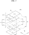
- FIG. 1 is a perspective diagram illustrating a battery having an electrode structure according to an embodiment of the present invention.
- FIG. 2 is a perspective diagram of the battery taken along the line A-A' in FIG. 1 .
- the battery 1000 may include the electrode assembly 100, an exterior body 200 for accommodating the electrode assembly 100 and an electrolyte 300.
- the electrode assembly 100 includes a cathode layer 110, an anode layer 120 facing the cathode layer 110, and a separation film 130 disposed between the cathode layer 110 and the anode layer 120.
- the electrode assembly 100 may be formed by laminating those members or winding after laminating them.
- the electrode assembly 100 may have a single layer structure, or a stacked multi-layer bending structure.
- the exterior body 200 may include a upper exterior layer 210 and a lower exterior layer 220 facing the upper exterior layer 210 in order to accommodate the electrode assembly 100 and the electrolyte 300.
- the upper exterior layer 210 and the lower exterior layer 220 may include an exterior sealing part ES in which some parts of edges (a peripheral part) of the upper exterior layer 210 and the lower exterior layer 220 are adhered, and an inner sealing part IS in which the inner peripheral sides of the upper exterior layer 210 and the lower exterior layer 220 are adhered.
- the electrode assembly 100 may be formed through a step for disposing an electrode assembly 100 between the upper exterior layer 210 and the lower exterior layer 220, a step for laminating the upper exterior layer 210 and the lower exterior layer 220, and a step for winding the upper exterior layer 210 and the lower exterior layer 220 after a laminating step.
- the cathode layer 110, the anode layer 120 and the separation film 130 may have a planar shape extending in a first direction D1 and a second direction D2.
- the cathode layer 110, the anode layer 120, and the separation film 130 may be stacked in the third direction D3.
- an orthogonal coordinate system may be constructed, but the present invention is not limited thereto.
- the third direction D3 has any value between 0 ° - 90° for a plane defined by the first direction D1 and the second direction D2 without being vertical to the plane. Therefore, these layers are may be stacked in an inclined way.
- At least one of the cathode layer 110 and the anode layer 120 may have a structure in which an active material layer suitable for a concerned polarity is coated on a planar current collector such as a metal foil.
- at least one of the cathode layer 110 and the anode layer 120 may also have a suitable structure to form a battery having flexibility. This will be described in detail later with reference to FIG. 3A to 3C .
- the cathode layer 110 may include at least more than one first openings OP11.
- the openings OP11 may be formed in the cathode layer 110.
- the first openings OP11 of the cathode layer 110 may be formed as a circular shape, a triangular shape, a quadrangle, an elliptical type, or the like.
- FIG. 1 illustrates the three first openings OP11 having different sizes. However, these shapes are only illustrative and the present invention is not limited thereto.
- the anode layer 120 may include at least more than one second openings OP12.
- the openings OP12 may be formed in the anode layer 120.
- the second openings OP12 of the anode layer 120 may be formed as a circular shape, a triangular shape, a quadrangle, an elliptical type, or the like.
- FIG. 1 illustrates the three second openings OP12 having different sizes. However, these shapes are only exemplary and thus, the present invention is not limited thereto.
- the separation film 130 may be made of a porous material which is filled with the electrolyte 300 and transfer of ions may be easily realized.
- the porous material may be polyethylene terephthalate, polyester, polyacetal, polyamide, polycarbonate, polyimide, polyether ether ketone, polyether sulfone, polyphenylene oxide, polyphenylene sulfide, polyethylene naphthalene, polyvinylidene fluoride, polyethylene oxide, polyacrylonitrile, polyvinylidene fluoride, hexafluoropropylene copolymer, polyethylene, polypropylene, and equivalents thereof, or combinations thereof.
- the listed materials are merely exemplary and the present invention is not limited thereto.
- a polyolefin series may also be used as the separation film 130.
- the separation film 130 may be in the form of a fiber or a membrane.
- the fibrous separation film may include a nonwoven fabric forming a porous web, and may be a Spunbond type formed by long an anodes or Melt blown type.
- the pore size and porosity of the separation film 130 may range within 30% to 95% and the average diameter of the pores may range from 0.01 ⁇ m to 10 ⁇ m.
- the pore size and porosity are less than 0.01 ⁇ m and approximately 30%, respectively, it may be difficult to impregnate the electrolyte with sufficient electrolyte due to a decrease in movement of the electrolyte precursor.
- the size and porosity are greater than about 10 ⁇ m and 95%, it may be difficult to maintain the physical properties and there is a high possibility that a short-circuit may occur between the cathode layer 110 and the anode layer 120.
- the thickness of the separation film 130 is not limited, it may be in the range of 1 ⁇ m to 100 ⁇ m, and it is preferable that the thickness is in the range of 5 ⁇ m to 50 ⁇ m.
- the thickness of the separation film 130 is less than 1 ⁇ m, it is difficult to maintain the mechanical properties, and when it exceeds 100 ⁇ m, it acts as a resistive layer, resulting in lowering the output voltage, and flexibility of a battery may be reduced.
- FIG. 1 Although a single separation film 130 is illustrated in FIG. 1 , the present invention is limited thereto, and two or more separation film 130 may be arranged. In this case, the shapes and the materials of more than two the separation films may be same or different.
- the length of the separation film 130 extending in the first direction D1 is longer than the lengths of the cathode layer 110 and the anode layer 120 extending in the direction D1.
- the separation film 130 may not sufficiently perform the function to efficiently move ions between the cathode layer 110 and the anode layer 120.
- a short-circuit may occur between the cathode layer 110 and the anode layer 120.
- the separation film 130 may include at least more than one third openings OP13 formed in the separation film 130.
- the third openings OP13 of the separation film 130 may be formed as a circular shape, a triangular shape, a quadrangle, or an ellipse.
- FIG. 1 shows three circular third openings OP13 of different sizes. However, these shapes are only exemplary and the invention is not limited thereto.
- the cathode layer 110, the anode layer 120, and separation film 130 disposed between the cathode layer 110 and the anode layer 120 may include at least more than one openings.
- the openings may be aligned in one direction to form the inner penetrating part TH1.
- the inner penetrating part TH1 may have a shape such as a circular shape, a triangular shape, a quadrangle, and an ellipse.
- FIG. 1 shows an example of an inner penetrating part TH1 including three circular first openings OP11, three circular second openings, OP12 and three circular third openings OP13.
- these shapes are only exemplary and the present invention is not limited thereto.
- the inner penetration part TH1 may be formed by aligning the first openings OP11 of the cathode layer 110, the second openings OP12 of the anode layer 120 and the third openings OP13 of the separation film 130.
- the width (the size) of the third openings OP13 of the separation film 130 may be smaller than the widths of the first openings OP11 the cathode layer 110 and the second openings OP12 of the anode layer 120.
- the width of the third openings OP13 of the separation film 130 may be larger than the widths of the first openings OP11 of the cathode layer 110 and the second openings OP12 of the anode layer 120, there are contacts among some parts of the cathode layer 110 and the anode layer 120, which are opposed to each other, and thus internal short-circuit may occur inside the third openings OP13 of the separation film 130. Therefore, it is preferable that the width of the third openings OP13 of the separation film 130 is formed smaller than the widths of the first openings OP11 of the cathode layer 110 or the second openings OP12 of the anode layer 120.
- the positive lead tab(not shown) and the negative lead tab(not shown) may be adhered to the cathode layer 110 and the anode layer 120 of the electrode assembly 100 by using a laser welding, an ultrasonic welding, or a conductive adhesive, so that a current flow may be made.
- the positive lead tab or the negative lead tab may be formed so as to protrude from the electrode assembly 100 toward the direction vertical to the direction in the electrode assembly 100 is wound.
- the exterior body 200 may include a upper exterior layer 210 and a lower exterior layer 220 facing the upper exterior layer 210 in order to accommodate the electrode assembly 100 and the electrolyte 300.
- the upper exterior layer 210 and the lower exterior layer 220 may include an exterior sealing part ES in which some parts of edges (a peripheral part) of the upper exterior layer 210 and the lower exterior layer 220 are adhered, and an inner sealing part IS in which the inner peripheral sides of the upper exterior layer 210 and the lower exterior layer 220 are adhered.
- the exterior body 200 may be formed by disposing the electrode assembly 100 between the upper exterior layer 210 and the lower exterior layer 220, and laminating the upper exterior layer 210 and the lower exterior layer 220, or winding the upper exterior layer 210 and the lower exterior layer 220 after laminating them.
- the exterior body 200 is arranged to prevent the electrode assembly 100 from swelling when the internal pressure of the secondary battery increases.
- it may be formed by a strong material to deformation.
- the upper exterior layer 210 may be formed by a metal such as a copper.
- the present invention is not necessarily limited to these examples, and the upper exterior layer 210 may be formed by various kinds of materials such as other metals, polymers, composite materials thereof, or a laminated structure thereof.
- the upper exterior layer 210 may include at least more than one fourth openings OP21 formed inside the upper exterior layer 210.
- the fourth openings OP21 of the upper exterior layer 210 may be formed as a circular shape, a triangular shape, a quadrangle, or an ellipse.
- FIG. 1 shows the three circular fourth openings OP21 having different sizes, respectively.
- these shapes are only exemplary and thus, the present invention is not limited thereto.
- At least the exterior surface of the exterior body 200 may be formed by a non-conductive material.
- the entire exterior body 200 may be uniformly formed by polymer, paper, or an electrically non-conductive material such as fabrics.
- the present invention is not limited to this embodiment, and the lower exterior layer 220 may be formed by other metals or various materials such as polymers.
- the lower exterior layer 220 may include at least more than one fifth openings OP22 formed within the lower exterior layer 220.
- the fifth openings OP22 of the lower exterior layer 220 may be formed as a circular shape, a triangular shape, a quadrangle, or an ellipse.
- FIG. 1 shows the three circular fifth openings OP22 having different sizes, respectively.
- these shapes are only exemplary and thus, the present invention is not limited thereto.
- the exterior body 200 may be formed by an inner core layer and an exterior coating layer.
- the inner core layer may be formed by a metal film so that a mechanical strength, a moisture resistance, or barrier properties may be secured.
- the exterior coating layer may be formed by an electrically nonconductive material for ensuring electrical insulation. In connection with the exterior body 200 wherein at least more than one surfaces are formed of an electrically non-conductive material, even if the electrode plates of the electrode assembly 100 are in contact with the exterior body 200, an internal short circuit of the assembly 100 generated due to the exterior body 200 may be prevented.
- the exterior sealing part ES is a section where formed by a part of edges(exterior periphery) of the upper exterior layer 210 and a part, and a part of edges(exterior periphery) of the lower exterior layer 220 are adhered each other.
- the electrode assembly 100 and the electrolyte 300 are accommodated inside the exterior body 200 by the exterior sealing part ES.
- the exterior sealing part ES may be formed by adhering the upper and lower exterior layers 210 and 220 via a heat fusion, an ultrasonic welding, or an adhesive.
- the lower exterior layer 220 may be arranged so as to face the upper exterior layer 210.
- the inner sealing part IS is a section where the inner circumferences of the upper and lower exterior layers 210 and 220 are adhered.
- the inner sealing part IS includes an inner penetration part TH1 and may form a battery penetration part TH2 which penetrates from the inner periphery of the upper exterior layer 210 to the inner periphery of the lower exterior layer.
- the battery penetration part TH2 may be formed as a circular shape, a triangular shape, a quadrangle, or an elliptical shape.
- FIG. 2 illustrates two battery penetration parts TH2. However, these shapes are only exemplary and the present invention is not limited thereto.
- the shape of the inner penetration part TH1 of the battery penetration part TH2 may be identical to that of the battery penetration part TH2. According to one embodiment of the present invention, the shape of the inner penetrating part TH1 of the battery penetrating part TH2 may be different from that of the battery penetrating part TH2.
- the battery penetrating part TH2 may be formed by aligning the inner penetration part TH1 formed by aligning the first openings OP11 of the cathode layer 110, the second openings OP12 of the anode layer 120, and the third openings OP13 of the separation film 130 in one direction; the fourth openings OP21 of the upper exterior layer 210; and the fifth openings OP 22 of the lower exterior layer 220 in one direction.
- the surfaces where the fourth openings OP21 of the upper exterior layer 210 are facing the fifth openings OP 22 of the lower exterior layer 220, or those opening are in a contact with each other may be formed by the inner sealing part IS. Therefore, the inner penetration part TH1 of the electrode assembly 100 may be sealed by the inner sealing part IS.
- the widths of the fourth openings OP21 of the upper exterior layer 210 and the fifth openings OP22 of the lower exterior layer 220 may be smaller than that of the inner penetration part TH1 of the electrode assembly 100.
- the fourth openings OP21 of the upper exterior layer 210 and the fifth openings OP22 of the lower exterior layer 220 are larger than the width of the inner penetration part TH1 of the electrode assembly 100, the exterior body 200 may not completely seal the electrode assembly 100 and thus, the electrolyte 300 may be leaked out from the sealing part IS.
- the efficiency of the battery 1000 may be tremendously reduced. Therefore, the widths of the fourth openings OP21 of the upper exterior layer 210 and the fifth openings OP22 of the lower exterior layer 220 may be smaller than that of the widths of the first openings OP11, the second openings OP12, and the third openings OP13 of the electrode assembly 100.
- the widths of the battery penetration part TH2 formed by the fourth openings OP21 of the upper exterior layer 210, and the fifth openings OP21 of the lower exterior layer 220 may be smaller, as compared with the width of the third openings OP13 of the separation film 130 of the electrode assembly 100.
- FIG. 3A through 3C are the magnified diagrams illustrating one electrode of an electrode assembly according to an embodiment of the present invention.
- the electrode 110a includes a metal fiber type current collector 111 and a particle-active material 112, and a liquid electrolyte or gelling and/or a solidified electrolyte 300 between them is provided.
- the electrode 110a may be any one of a positive electrode and a negative electrode, and the invention is not limited to thereto.
- the electrode 110a may include a metal fiber type current collector for forming a conductive network wherein a plurality of metal fibers are in contact with each other, and a heat conduction network.
- the metal-fiber-type current collector may form a conductive network having porosity, wherein a plurality of metal fibers are randomly arranged, physically contacted with each other, are bended or broken, and tangled to each other, and thereby, they are mechanically fastened each other.
- the conductive network may form non-woven structure.
- the plurality of metal fibers may optionally include two or more different kinds of metals or other metals having different lengths.
- the metal fiber type current collector include stainless steel, aluminum, nickel, titanium, copper or any one of alloys thereof, or combinations thereof.
- a cathode layer 110 an aluminum which is not oxidized at a high potential region, or alloys thereof may be used for forming the metal fiber type current collector.
- an anode layer 120 a cooper, a stainless steel, nickel or alloys thereof which are electrochemically inactive in the low operating potential may be used for forming a metal fiber type collector.
- a metal foil (not shown) of a plate shape may be combined to one side of the metal fiber type current collector. Combination of the metal fiber type current collector and the metal foil may be implemented by adhering via a heat fusion, an ultrasonic welding or an adhesive.
- cathode layer 110 and the anode layer 120 including a structure of a metal fiber type current collector are described. But, these embodiments are only exemplary, and only any one of the cathode layer 110 and the anode layer 120 may have the structure of the metal fiber type current collector.
- the cathode layer 110 or the anode layer 120 may be provided by impregnating the metal fiber type current collector with an active material, or by coating a metal fiber of the metal fiber type current collector.
- a metal fiber type current collector 111 is generally formed as a straight line and a bended type, but as an another embodiment of the invention, the metal fiber current collector 111 may be molded so as to have a regular and/or an irregular shape such as a curly or spiral shape
- the metal fiber type current collector 111 having the above-mentioned a straight line, a bended type, or an regular and/or an irregular shape form a heat conduction network with high thermal conductivity via the physical contacts with each other in the electrode 110a.
- the heat conduction network is formed when more than one metal fiber type current collector 111 are bended or broken, and tangled to each other, mutually contacted or combined.
- the heat conduction network may have porosity, mechanical firmness and flexibility obtained due to the fiber properties.
- the active material 112 in the form of particles is tightly bonded to the heat conduction network provided by a metal fiber type current collector 111. Since the active material 112 is tightly bonded to the heat conduction network, the size of the pores and porosity of the heat conduction network to form the metal fiber type current collector 111 may be adjusted properly. A step for adjusting the size of pores and adjustment of the porosity may be carried out by adjusting a mixing weight ratio when being mixed with the active material 112 in the entire electrode 110a of the metal fiber type current collector 111.
- the gelled or solidified electrolyte 300 is tightly bonded to the pore provided between a metal fiber type current collector 111 and an active material 112. Further, the gelled or solidified electrolyte 300 is arranged so that it may be in contact with the entire interface of an active material 112 of a particle form. Accordingly, in connection with the electrolyte 300, a wetting and the contact properties are improved as far as the active material 112 is concerned, so that a contact resistance between the electrolyte 300 and the active material 112 may be reduced, and the electrical conductivity may be increased.
- a binder 114 may be further added to the electrode 110a, so that the active material 12 in the form of particles may be tightly bonded to the heat conduction network.
- the binder 114 may be, for example, the polymer materials such as vinylidene fluoride-hexafluoropropylene copolymer(PVdF-co-HFP), polyvinylidenefluoride(PVdF), polyacrylonitrile, polymethylmethacrylate, polytetrafluoroethylene(PTFE), styrene-butadiene rubber styrenebutadiene rubber(SBR), polyimide, polyurethane-based polymer, polyester-based polymers, and ethylene-propylene-diene copolymer(EPDM) be a polymer-based material.
- the present invention is not necessarily limited to these examples, and the material of the binder having a predetermined cohesive power and stability under the electrochemical environment while dissolving in the electrolyte 300 may be
- a conductive material 115 may be further added to the electrode 110a for improving the electrical conductivity of the electrode 110a.
- the conductive material 115 may be, for example, fine carbon such as carbon black, acetylene black, ketchen black, and ultra-fine graphite particles; a nano metal particle paste; or ITO (indium tin oxide) paste; or the nano structure having a large specific surface area and a low resistance such as a carbon nano tube.
- the metal fiber type current collector 111 having a micro size corresponding to the active material 112 is able to perform the same role as the role of the conductive material 115, there is an advantage that may suppress the increase in manufacturing cost due to the addition of the conductive material 115.
- porous ceramic particles may be further added into the electrode 110a.
- the porous ceramic particles may include, for example, porous silica.
- the porous ceramic particles facilitate the electrolyte 300 to be impregnated into the electrode 110a.
- the electrolyte 300 may be accommodated in the exterior body 200 of the battery 1000.
- the electrolyte 300 may be absorbed in the electrode assembly 100.
- the battery 1000 may be formed by absorbing a suitable aqueous electrolyte electrode solution including a salt such as potassium hydroxide(KOH), potassium bromide(KBr), potassium chloride (KCL), zinc chloride(ZnCl 2 ) and sulfuric acid(H 2 SO 4 ) into the cathode layer 110, the anode layer 120, and/or the separation film 130 of the electrode assembly.
- a salt such as potassium hydroxide(KOH), potassium bromide(KBr), potassium chloride (KCL), zinc chloride(ZnCl 2 ) and sulfuric acid(H 2 SO 4 )
- the battery 1000 may be a non-aqueous electrolyte such as ethylene carbonate, propylene carbonate, dimethyl carbonate or di-ethyl carbonate which include a lithium salt such as LiClO 4 or LiPF 6 .
- a suitable cooling device or battery managing system may be connected to the battery 1000 for controlling a power supply characteristics and stability of a battery 1000 while being used.
- FIG. 4 is a perspective diagram showing a laminated structure wherein a secondary battery having a battery penetration is laminated on a printed circuit board according to one embodiment of the present invention.
- the battery 1000 may be disposed on a printed circuit board PCB.
- PCB Printed Circuit Board
- PCB is a printed wiring plate for forming the electrical wirings between the electronic components on an insulating layer according to a circuit design, and PCB is also referred as PCB substrate, a printed circuit plate, or a printed wiring board.
- a printed circuit board(PCB) is defined as a board formed from a FR4 substrate, MCPCB (metal core printed circuit board), and a cast polymer resin cross-linked by using ultraviolet radiation, or a circuit board selected from the structures of any other circuit boards which could be easily understood by the person in the related art.
- such a printed circuit board is being manufactured by a step for mounting a copper foil on the surfaces of a phenol resin or an epoxy resin insulating layer; a step for forming necessary circuit patterns by etching the copper foil according to the circuit pattern; and a step for densely mounting various kinds of electronic components such as IC chips, capacitors, resistors on the circuit patterns,
- the printed circuit board is classified into a single substrate, a double-sided substrate or a multi-layer substrate according to the number of circuit layers and insulating layers. As the number of layers in increasing, the mounting capability of the electronic components are getting more excellent.
- a PCB including the multi-layers for producing are used for producing the products requiring very high precision.
- the printed circuit board(PCB) includes, a substrate, electronic components(CD) formed on the substrate.
- the electronic components (CD) may be the components of a common printed circuit board such as at least more than one IC chips, capacitors, resistors.
- the electrode assembly 100 between the upper exterior layer 210 and the lower exterior layer 220, and the exterior body 200 may be formed by laminating the upper exterior layer 210 and the lower exterior layer 220 or winding the upper exterior layer 210 and the lower exterior layer 220 after laminating them.
- the battery 1000 may include the fourth openings OP21 and the fifth openings OP22 formed in the electrode assembly 100 and the exterior body 200.
- the fourth openings OP21 and the fifth openings OP22 may be formed as a circular shape, a triangular shape, a quadrangle, and an elliptical shape.
- FIG. 1 shows three circular fourth openings OP21 and fifth openings OP22 having different sizes.
- these shapes are only exemplary, and the present invention is not limited to these shapes.
- the listed shapes are only exemplary, and the present invention is not limited to thereto.
- the electronic components(CD) of the printed circuit board(PCB) may be inserted into, or may be protruded from the battery 1000 after passing through the battery penetration part TH2 formed by aligning the first openings OP11, the second opening OP12, the third opening OP13, the fourth opening OP21 and the fifth openings OP22 of the battery 1000 in one direction.
- the electronic components(CD) of a printed circuit board(PCB) may be assembled with the battery 1000. It may not be necessary to secure a space for an additional printed circuit board(PCB) for accommodating the battery 1000.
- the inner penetration part TH1 is formed in the electrode assembly 100 consisting of the cathode layer, the anode layer, and the separation film.
- a battery or a battery cell including the battery penetration part TH2 passing through from the upper to the lower exterior layer exterior layer may be provided by forming the battery penetration part TH2 including the inner penetration part TH1 from the exterior body 200 for accommodating the electrode assembly 100 therein.
- the battery may be stacked on a printed circuit board so as to be mounted.
- the central part of the battery when the internal pressure of the secondary battery is increased, the central part of the battery remarkably swells as compared with the periphery of the battery. This phenomenon that the central part of the battery swells according to the increasing pressure may be prevented. Therefore, stability of the battery may be enormously improved.
- the battery penetration unit may prevent the electrode assembly 100 from being moved in the inner space of the exterior body 200. Therefore, when the electrode assembly 100 moves in the inner space, the problems that the electrode assembly 100 is damaged or a contact is made between the electrode plates of different polarities of the other electrode assembly 100 and thus, an internal short circuit occurs may be prevented.
- Figure 5 is a perspective diagram illustrating a structure in which a secondary battery having a battery penetration unit is laminated on the drone in accordance with one embodiment of the present invention.
- the battery 1000 may be installed in the drone DN.
- drone DN may be referred to the drone.
- size or shape of drone DN may be varied in accordance with the intended use.
- the drone DN may be used for military, rescue, or civilian purposes.
- the drone DN includes at least more than one rotary blade, and a rotor and a driving unit for rotating each of the rotary blade.
- the rotary blades may be rotated by power force of a drive unit.
- the driving unit at least more than one motor, the camera or GPS may be installed.
- Drone DN may be controlled by an adjusting device.
- drone DN may be adjusted by wireless adjustment device or automatic navigation equipments.
- the battery 1000 including a battery penetration unitTH2 may be installed on a drone DN. Furthermore, the drone DN having passed through the battery penetration unit TH2 of the battery 1000 drone DN is inserted through the battery penetration unit TH2, or may be projected. Therefore, the drone DN may be assembled together with the battery 1000 and thus, it is not necessary to install an additional power supply that provides power on the drone DN.
- an inner penetration part TH1 is formed in an electrode assembly 100 consisting of a cathode layer, an anode layer, and a separation film, and the battery penetration unit TH2 including an inner penetration part TH1 is formed from an exterior body 200 for accommodating the electrode assembly 100 therein.
- a battery or a battery cell may be provided in which the battery penetration unit TH2 passing through from the upper exterior layer to the lower exterior layer is formed.
- a battery is installed on a drone through the battery penetration unit TH2, and the battery may be mounted on the drone.
- various kinds of shape and size of the lithium secondary battery may be realized and it is also possible to miniaturize the drone while enhancing capacity of the secondary battery itself by reducing the need for a power supply device for providing a separate power source.
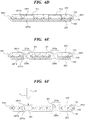
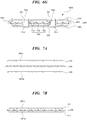
- FIG. 6A-6G are cross-sectional diagrams illustrating a method of manufacturing a secondary battery according to an embodiment of the present invention.
- the electrode assembly 100 is formed.
- the cathode layer 110, the anode layer 120 and the separation film 130 disposed between the cathode layer 110 and the anode layer 120 are prepared.
- the cathode layer 110 may include at least more than one first openings OP11 formed in one region.
- the first openings OP11 may be formed on the cathode layer 110 of a plate shape by using a punching equipment P.
- the punching equipment P may comprise an end portion of a pin shape capable of passing through the surface of the cathode 110.
- a drill, an iron or a hollow pipe may be used as the punching equipment.
- the anode layer 120 may include at least more than one second openings OP12 formed on one region.
- the second openings OP12 may be formed on the anode layer 120 of the plate shape by a punching equipment.
- the punching equipment P may comprise an end portion of a pin shape capable of passing through the surface of the anode layer 120.
- a drill, an iron or a hollow pipe may be used as a punching equipment.
- the separation film 130 may include at least more than one third openings OP13 formed on one region.
- the third openings OP13 is formed on the film 130 of a plate shape by a punching equipment P.
- the punching equipment P may include an end portion of a pin shape capable of passing through the surface of the separation film 130.
- a drill, an iron or a hollow pipe may be used as a punching equipment.
- the widths of the third openings OP13 of the separation film 130 may be formed such that they are smaller than those of the first openings OP11 of the cathode layer 110 and the second openings OP12 of the anode layer 120. If the widths of the third openings OP13 of the separation film 130 may be formed such that they are larger than those of the first openings OP11 of the cathode layer 110 and the second openings OP12 of the anode layer 120, the internal short-circuit of the cathode layer 110 and the anode layer 120 may occur. Therefore, it is preferable that the third openings OP13 of the separation film 130 are smaller than those of the first openings OP11 of the cathode layer 110 and the second openings OP12 of the anode layer 120.
- the separation film 130 may be parallel to the cathode layer 110 and anode layer 120. Furthermore, a porous separation film as well as the separation film 130 may be formed additionally between the cathode layer 110 and anode layer 120. According to one embodiment of the present invention, the length of the uni-directionally formed separation film 130 may be longer than the length of uni-directionally formed the cathode layer 110 and the anode layer 120. When the length of the separation film 130 is formed shorter than the length of the cathode layer 110 and anode layer 120, the separation film 130 may not effectively perform a function moving ions between the cathode layer 110 and the anode layer 120. As a result, a short-circuit may occur between the cathode layer 110 and the anode layer 120.
- a positive lead tab not shown and a negative lead tab not shown may be adhered to the cathode layer 110 and the anode layer 120 in electrode assembly 100, respectively via a welding process such as a laser welding, ultrasonic welding, and resistance welding, or a conductive adhesive, so that current flow may be made swimmingly.
- the positive electrode lead tab or the negative electrode lead tab may be formed so as to protrude from the electrode assembly 100 toward the direction perpendicular to the direction in which the electrode assembly 100 is wound.
- the anode layer 120, the separation film 130 and the cathode layer 110 may be laminated according to the sequential order as described above.
- the cathode layer 110, the separation film 130 and the anode layer 120 may be arranged in one direction and may be stacked according to the sequential order as described above.
- the first openings OP11 of the cathode layer 110, the second openings OP12 of the anode layer 120, and the third openings OP13 of the separation film130 may be arranged in one direction so that an inner penetration unit TH1 may be formed.
- the inner penetration unit TH1 may be formed so as to have shapes such as a circle, a triangle, a quadrangle, and an ellipse may be formed.
- shapes such as a circle, a triangle, a quadrangle, and an ellipse may be formed.
- the enumerated shapes are described only as examples and the present invention is not limited to these shapes.
- an exterior body 200 may be formed in order to accommodate the electrode assembly 100 and electrolyte 300, and a upper exterior layer 210 and the lower exterior layer 220 of a plate shape may be prepared in order to form an exterior body 200.
- an exterior sealing part ES1 may be formed by attaching the upper exterior layer 210 and the lower exterior layer 220 to one side of the electrode assembly 100, and sealing the edge zone of the upper exterior layer 210 and the lower exterior layer 220.
- the portion where the edge surfaces of the upper exterior layer 210 and the exterior surface layer 220 are bonded to each other may be an exterior sealing part ES1.
- the exterior sealing part ES1 may cover the cathode layer 110, the anode layer 120 and a lateral side of the separation film 130 of the electrode assembly 100.
- the exterior sealing part ES1 may be formed by compressing the edges of the upper exterior layer 210 and the lower exterior layer 220 to each other using a pressing equipment. Further, the exterior sealing part ES1 may be formed by attaching the edges of an upper exterior layer 210 and a lower exterior layer 220 to each other via a heat fusion, an ultrasonic welding or an adhesive.
- the exterior sealing part ES1 may be formed by adhering some portions of the respective edge surfaces of an upper exterior layer 210 and the lower exterior layer 220a. At this time, an electrolyte injection hole EI through which electrolyte 300 is to be injected may be further formed along the respective edge portions of an upper exterior layer 210 and the lower exterior layer 220.
- an inner sealing part IS1 it is possible to form an inner sealing part IS1 by adhering the respective opposite parts of the upper exterior layer 210 and the lower exterior layer 220 of the exterior body 200.
- the inner sealing part IS1 may be the part where a portion 210a of the upper exterior layer 210 at which the inner penetration part TH1 illustrated in FIG. 6G is to be formed and a portion 220a of the lower exterior layer 220 are mutually adhered.
- the inner sealing part IS1 may be formed by mutually compressing the portion 210a of the upper exterior layer 210 corresponding to a region where the inner penetration part TH1 is to be formed, and the portion 220a of the lower exterior layer 220 corresponding to a region where the inner penetration part TH1 is to be formed via a pressing equipment. Further, the inner sealing part IS1 may be formed by mutually compressing the portion 210a of the upper exterior layer 210 corresponding to a region where the inner penetration part TH1 is to be formed, and the portion 220a of the lower exterior layer 220 corresponding to a region where the inner penetration part TH1 is to be formed via a heat fusion, an ultrasonic welding or an adhesive.
- a punching equipment P may penetrate from the portion 210a of the upper exterior layer 210 corresponding to a region where the inner sealing part IS1 is to be formed, until the portion 220a of the lower exterior layer 220 corresponding to a region where the inner sealing part IS1 is to be formed.
- the moving direction of the punching equipment P penetrating from the portion 210a of the upper exterior layer 210 to the portion 220a of the lower exterior layer 220 may be represented by an arrow in FIG. 5F .
- the punching equipment P may include a punching part C which may penetrate from the portion 210a of the upper exterior layer 210 corresponding to a region where the inner sealing part IS1 is formed, to the portion 220a of the lower exterior layer 220 corresponding to a region where the inner sealing part IS1 is formed.
- the punching portion C of the punching equipment P may include an end of a sharp pin shape.
- a drill, an iron or a hollow pipe may be used as the punching equipment.
- At least more than one fourth opening OP21 passing through the upper exterior layer 210 corresponding to a region where the inner sealing part IS1 is formed; at least more than one fifth opening OP22 passing through the lower exterior layer 220 corresponding to a region where the inner sealing part IS 1 is formed, may be formed via a punching equipment P.
- the fourth opening OP21 and the fifth opening OP22 may be formed as a circle, a triangle, a quadrangle, an ellipse. However, these shapes are only to be illustrative of the present invention and it is not limited thereto.
- the fourth openings OP21 are formed from the portion 210a of the upper exterior layer and the fifth openings OP22 are formed from the portion 220a of the lower exterior layer OP22 is formed.
- the respective surfaces of the upper exterior layer 210 and the lower exterior layer 220 adjacent to the inner penetration part TH1 may be adhered to each other.
- the widths of the fourth openings OP21 of the upper exterior layer 210 and the opening OP22 of the lower exterior layer 220 may be formed smaller than the width of the inner penetration part TH1 of the electrode assembly 100.
- the widths of the fourth openings OP21 of the upper exterior layer 210 and the openings OP22 of the lower exterior layer 220 may be formed larger than the width of the inner penetration part TH1 of the electrode assembly 100, since the exterior body 200 may not completely seal the electrode assembly 100, there is a possibility that the electrolyte 300 may be leaked from the inner sealing part IS1. Further, if the electrolyte 300 is discharged to an outside space from the exterior body 200, the efficiency of the battery 1000 may be reduced remarkably. Thus, the exterior body 200 may be formed smaller than those of the fourth openings OP21 of the upper exterior layer 210 and the opening OP22 of the lower exterior layer.
- a battery penetration part TH2 at least more than one passing through the fourth openings OP21 of the upper exterior layer 210, the first openings OP11 of the cathode layer 110, the third openings OP13 of the separation membrane 130, the second openings OP12 of the anode layer 120, and the fifth openings OP22 of the lower exterior layer 220 may be formed by using the punching equipment P.
- the battery penetration part TH2 may be formed by aligning the first openings OP11 of the cathode layer 110, the second openings OP12 of the anode layer 120, the third openings OP13 of the separation membrane 130, the fourth openings OP21 of the upper exterior layer 210, and the fifth openings OP22 of the lower exterior layer 220 in one direction.
- the battery penetration part TH2 may be formed as a circle, a triangle, a quadrangle, an ellipse.
- the shape of the battery penetration part TH2 may be changed according to a shape of the punching portion C of the punching equipment P.
- the listed shapes are only illustrative of the present invention and it is not limited to these shapes.
- the inner penetration part TH1 and the battery penetration part TH2 may be formed as a same shape. If the inner penetration part TH1 and the battery penetration part TH2 may are formed as a same shape, it is possible to extend the internal space of the exterior body 200. Thus, the amount of an electrolyte 300 that may be injected into the exterior body 200 may be maximized.
- the shapes of the inner penetration part TH1 and the battery penetration part TH2 may be formed differently.
- the width of the battery penetration part TH2 which is formed by fourth openings OP21 of the upper exterior layer 210 and the fifth openings OP22 of a lower exterior layer 220 may be formed to be smaller.
- the electrolyte 300 may be injected to the inside of the exterior member 200 through an electrolyte injection hole EI formed on the exterior body 200.
- the electrolyte injection hole EI through which the electrolyte 300 is injected may be formed in advance by enabling some portions of the edge surfaces of the upper exterior layer 210 and the lower outer layer 220 not to be adhered.
- the electrolyte 300 may be injected into the inside of the exterior body 200 through the injection hole EI formed on the exterior body 200.
- the electrolyte injection hole EI through which the electrolyte 300 is injected may be formed in advance by enabling some portions of the edge surfaces of the upper exterior layer 210 and the lower outer layer 220 not to be adhered.
- the electrolyte Injection hole EI may be sealed in order to prevent the leakage of the electrolyte 300.
- An electrolyte injection hole EI may be completely sealed by using a heat fusion method, an ultrasonic welding method, or other separate adhesives.
- the exterior body 200 including the exterior sealing part ES1 may be formed from the upper exterior layer 210 and the lower exterior layer 220. The exterior body 200 may accommodate and cover the electrode assembly 100. Further, the exterior body 200 may protect the electrode assembly 100 and the electrolyte 300 from the outside environment.
- the electrode assembly 100, the exterior body 200 covering the electrode assembly 100, and the battery 1000 including the electrolyte 300 may be formed from these processes.
- a battery 1000 may be installed on the inside part or the outside part of the electronic products via the battery penetration part TH2.
- the parts of the electronic products may be inserted into or projected from TH2.
- the inner penetration part TH1 is formed, and a battery penetration part TH2 including the penetration part TH1 from the exterior body 200 for accommodating the electrode assembly 100 therein is formed on an electrode assembly 100 consisting of the anode layer, the cathode layer, and the separation film.
- a battery or a battery cell may be provided wherein the battery penetration part TH2 passing through from the upper exterior layer 210 to the lower portion 220 is formed. Since the electronic component are inserted and mounted on a printed circuit board via the battery penetration part TH2 and the battery may be stacked to be mounted, so the need for the additional battery receiving space is reduced. As a result of it, it is possible to realize various kinds of shapes and sizes of the lithium secondary battery and to increase the capacity of the secondary battery itself, while enabling the electronic products to be miniaturized.
- the battery penetration part TH2 may prevent the problem that the electrode assembly 100 is moving inside the exterior body 200.
- the problem that the electrode assembly 100 is damaged due to movement of the electrode assembly 100 or internal short circuit takes place due to contacts between the plates of other polarities of the other electrode assembly 100 may be prevented.
- FIG. 7A-7G are cross-sectional diagrams illustrating a method of manufacturing a secondary battery according to another embodiment of the present invention.
- the electrode assembly 100 is formed.
- the cathode layer 110, the anode layer 120 and the separation film 130 disposed between the cathode layer 110 and the anode layer 120 are prepared in order to form the electrode assembly 100.
- the cathode layer 110 may include at least more than one the first openings OP11 formed on a region.
- the first openings OP11 may be formed on the cathode layer 110 of a plate shape using a punching equipment.
- the punching equipment P may include an end of a pin shape capable of passing through the surface of the cathode layer 110.
- a drill, an iron or a hollow pipe may be used as the punching equipment.
- the anode layer 120 may include at least more than one the second openings OP12 on one region.
- the second openings OP12 may be formed on the anode layer 120 of a plate shape using a punching machine.
- the punching equipment P may include an end of a pin shape capable of passing through the surface of the anode layer 120.
- a drill, an iron or a hollow pipe may be used as a punching equipment.
- the separation film 130 may be disposed between the cathode layer 110 and anode layer 120.
- the separation film 130 may have a plate shape.
- at least more than one openings may be formed after forming the electrode assembly 100 so that the first penetration part TH1 and the second penetration part TH2 described later may be formed.
- the separation film 130 may be parallel to the cathode layer 110 and anode layer 120.
- a porous separator may be further formed in addition to a separation film 130 between the cathode layer 110 and the anode layer 120.
- the length of the separation film 130 formed in one direction may be longer than the lengths of the cathode layer 110 and the anode layer 120 formed in one direction. If the length of the separation film 130 is formed shorter than those of the cathode layer 110 and the anode layer 120, the separation film 130 may not perform sufficiently efficient movement of ions passing between the cathode layer 110 and the anode layer 120, and thus, a short circuit may occur between the cathode layer 110 and the anode layer 120.
- a positive lead tab(not shown) and a negative lead tab(not shown) may be adhered to the cathode layer 110 and the anode layer 120 of the electrode assembly 100 by a laser welding, an ultrasonic welding, a resistance welding or a conductive adhesive so that the currents may flow swimmingly.
- the positive electrode lead tab or the negative electrode lead tab may be formed so as to protrude from the electrode assembly 100 toward the direction vertical to the direction in which the electrode assembly 100 is wound. hode
- the anode layer 120, the separation film 130 and the cathode layer 110 may be laminated according to the sequential order as described above.
- the anode layer 120, the separation film 130 and the cathode layer 110 may be aligned in one direction and be stacked according to the above stacked order.
- the separation film 130 may be disposed between the first openings OP11 of the cathode layer 110 and the second openings OP12 of the anode layer 120.
- an exterior body 200 may be formed to accommodate the electrode assembly 100 and electrolyte 300.
- the upper exterior layer 210 and the lower exterior layer 220 of a plate shape prepared may be prepared in order to form an exterior member 200.
- an exterior sealing part ES2 may be formed via a step for attaching the upper exterior layer 210 and the lower exterior layer 220 to one side of the electrode assembly 100, and a step for sealing the edge zone of the upper exterior layer 210 and the lower exterior layer 220.
- the portion where the edge surfaces of the upper exterior layer 210 and the lower exterior layer 220 are adhered to each other may be the exterior sealing part ES2 at the edges of the upper exterior layer 210 and the lower exterior layer 220.
- the exterior sealing part ES2 may cover the lateral sides of the cathode layer 110, the anode layer 120 and the separation film 130 of the electrode assembly 100.
- the exterior sealing part ES2 may be formed by compressing the edges of the upper exterior layer 210 and the lower exterior layer 220 by using a pressing equipment. Further, the exterior sealing part ES2 may be formed by attaching the edges of the upper exterior layer 210 and the lower exterior layer 220 by a heat fusion, an ultrasonic welding or an adhesive.
- the exterior sealing part ES2 may be formed by adhering some portions of the respective edge surfaces of an upper exterior layer 210 and the lower exterior layer 220a.
- an electrolyte injection hole EI through which electrolyte 300 is to be injected may be further formed along the respective edge portions of an upper exterior layer 210 and the lower exterior layer 220.
- FIG. 7E it is possible to form an inner sealing part IS2 by adhering the respective opposite parts of the upper exterior layer 210 and the lower exterior layer 220 of the exterior body 200.
- the inner sealing part IS2 may be the part where a portion 210a of the upper exterior layer 210 and a portion 220a of the lower exterior layer 220, at which the inner penetration part TH2 illustrated in FIG. 7G is to be formed, are mutually adhered.
- the inner sealing part IS2 may be formed by mutually compressing the portion 210a of the upper exterior layer 210 corresponding to a region where the inner penetration part TH2 is to be formed, the portion 220a of the lower exterior layer 220 corresponding to a region where the inner penetration part TH2 is to be formed, and a portion of the separation film 130 corresponding to a region where the inner penetration part TH2 is to be formed, via a pressing equipment.
- the inner sealing part IS2 may be formed by mutually compressing the portion 210a of the upper exterior layer 210 corresponding to a region where the inner penetration part TH2 is to be formed, the portion 220a of the lower exterior layer 220 corresponding to a region where the inner penetration part TH2 is to be formed, and a portion of the separation film 130 corresponding to a region where the inner penetration part TH2 is to be formed, via a heat fusion, an ultrasonic welding or an adhesive.
- a punching equipment P may pass through the portion 210a of the upper exterior layer 210 corresponding to a region where the inner sealing part IS2 is to be formed, a portion of the separation film 130 corresponding to a region where the inner penetration part TH2 is to be formed, and the portion 220a of the lower exterior layer 220 corresponding to a region where the inner sealing part IS2 is to be formed.
- the moving direction of the punching equipment P passing through the portion 210a of the upper exterior layer 210, a portion of the separation film 130 corresponding to a region where the inner penetration part TH2 is to be formed, and the portion 220a of the lower exterior layer 220 may be represented by an arrow in FIG.
- the punching equipment P may include a punching part C which may pass through the portion 210a of the upper exterior layer 210 corresponding to a region where the inner sealing part IS2 is formed, a portion of the separation film 130 corresponding to a region where the inner sealing part IS2 is to be formed, and the portion 220a of the lower exterior layer 220 corresponding to a region where the inner sealing part IS2 is formed in a sequential order as above.
- the punching portion C of the punching equipment P may include an end of a sharp pin shape. For example, a drill, an iron or a hollow pipe may be used as the punching equipment.
- the punching part C it is possible to make the punching part C pass through the portion 210a of the upper exterior layer 210 corresponding to the area of the inner sealing part IS2, a portion of the separation film 130 corresponding to a region where the inner sealing part IS2 is formed, and the portion 220a of the lower exterior layer 220 in a sequential order as above.
- the punching equipment P may pass through the upper exterior layer 210 corresponding to a region where the inner sealing part IS2 is formed, the separation film 130 and the lower exterior layer 220.
- the battery penetration part TH2 including at least more than one inner penetration part TH1 may be formed.
- the inner penetration part TH1 may be an opening passing through the cathode layer 110, and the anode layer 120 and the separation film 130 between the cathode layer 110 and anode layer 120, under a state that the cathode layer 110, and the anode layer 120 and the separation film 130 between the cathode layer 110 and anode layer 120 are being aligned in one direction.
- the battery penetration part TH2 may be an opening passing through the upper exterior layer 210, the cathode layer 110, and the anode layer 120, the separation film 130 between the cathode layer 110 and anode layer 120, and the lower exterior layer 220, under a state that the upper exterior layer 210, the cathode layer 110, the anode layer 120, the separation film 130 between the cathode layer 110 and anode layer 120, and the lower exterior layer 220 are being aligned in one direction.
- inner the inner penetration part TH1 and a battery and the battery penetration part TH2 may be a shape such as a circle, a triangle, a quadrangle, an elliptical type.
- these shapes are not intended to be only illustrative of the present invention and it is not limited thereto. Since the battery penetration part TH2 passing through the portion 210a of the upper exterior layer, the separation film 130 and the lower exterior layer is formed, the respective surfaces of the upper exterior layer 210, the separation film 130 and the lower exterior layer 220 may be adhered to each other. According to one embodiment of the present invention, the shape of the battery penetration part TH2 including the inner penetration part TH1 may be changed in accordance with the shape of the punching portion C of the punching device P.
- the listed shapes according to the present invention are only illustrative and the present invention is not limited to them.
- the width of the battery penetration part TH2 be formed smaller than those of the first openings OP11 of the cathode layer 110 and the second openings OP12 of the anode layer 120. If the width of the battery penetration part TH2 may be formed larger than those of the first openings OP11 of the cathode layer 110 and the second openings OP12 of the anode layer 120, the internal short-circuit of the cathode layer and the anode layer may occur. Therefore, it is preferable that the width of the battery penetration part TH2 is smaller than those of the first openings OP11 of the cathode layer 110 and the second openings OP12 of the anode layer 120.
- the electrolyte 300 may be injected to the inside the exterior member 200 through the electrolyte injection hole EI formed on the exterior body 200.
- the electrolyte injection hole EI through which the electrolyte 300 is injected may be formed in advance by enabling some portions of the edge surfaces of the upper exterior layer 210 and the lower outer layer 220 not to be adhered.
- the electrolyte 300 may be injected into the inside of the exterior body 200 through the injection hole EI formed on the exterior body 200.
- the electrolyte injection hole EI through which the electrolyte 300 is injected may be formed in advance by enabling some portions of the edge surfaces of the upper exterior layer 210 and the lower outer layer 220 not to be adhered.
- the electrolyte Injection hole EI may be sealed in order to prevent the leakage of the electrolyte 300.
- An electrolyte injection hole EI may be completely sealed by using a heat fusion method, an ultrasonic welding method, or other separate adhesives.
- the exterior body 200 including the exterior sealing part ES2 and the inner sealing part IS2 may be formed from the upper exterior layer 210, the separation film 130 and the lower exterior layer 220.
- the exterior body 200 may accommodate and cover the electrode assembly 100. Further, the exterior body 200 may protect the electrode assembly 100 and the electrolyte 300 from the outside environment.
- the electrode assembly 100, the exterior body 200 covering the electrode assembly 100, and the battery 1000 including the electrolyte 300 may be formed from these processes.
- a battery 1000 may be installed on the inside part or the outside part of the electronic products via the battery penetration part TH2.
- the parts of the electronic products may be inserted into or projected from TH2.
- a battery penetration part TH2 including the penetration part TH1 is formed.
- a battery or a battery cell may be provided wherein the battery penetration part TH2 passing through from the upper exterior layer 210 to the lower portion 220 is formed. Since the electronic component mounted on a printed circuit board are inserted and arranged via the battery penetration part TH2 and thus, the battery may be stacked to be mounted on a printed circuit board, so the need for the additional battery receiving space is reduced. As a result of it, it is possible to realize various kinds of shapes and sizes of the lithium secondary battery and to increase the capacity of the secondary battery itself, while enabling the electronic products to be miniaturized.
- the battery penetration part TH2 in the battery 1000 may prevent the problem that the electrode assembly 100 is moving inside the exterior body 200.
- the problem that the electrode assembly 100 is seriously damaged due to movement of the electrode assembly 100 or internal short circuit takes place due to contacts between the plates of other polarities of the other electrode assembly 100 may be prevented.
Landscapes
- Chemical & Material Sciences (AREA)
- Chemical Kinetics & Catalysis (AREA)
- Electrochemistry (AREA)
- General Chemical & Material Sciences (AREA)
- Engineering & Computer Science (AREA)
- Manufacturing & Machinery (AREA)
- Materials Engineering (AREA)
- Microelectronics & Electronic Packaging (AREA)
- Secondary Cells (AREA)
- Sealing Battery Cases Or Jackets (AREA)
- Battery Electrode And Active Subsutance (AREA)
- Cell Electrode Carriers And Collectors (AREA)
- Cell Separators (AREA)
Applications Claiming Priority (2)
| Application Number | Priority Date | Filing Date | Title |
|---|---|---|---|
| KR1020150122154A KR101749409B1 (ko) | 2015-08-28 | 2015-08-28 | 이차 전지 및 이의 제조 방법 |
| PCT/KR2016/009465 WO2017039232A1 (ko) | 2015-08-28 | 2016-08-25 | 이차 전지 및 이의 제조 방법 |
Publications (2)
| Publication Number | Publication Date |
|---|---|
| EP3343685A1 true EP3343685A1 (de) | 2018-07-04 |
| EP3343685A4 EP3343685A4 (de) | 2019-05-08 |
Family
ID=58189028
Family Applications (1)
| Application Number | Title | Priority Date | Filing Date |
|---|---|---|---|
| EP16842198.0A Withdrawn EP3343685A4 (de) | 2015-08-28 | 2016-08-25 | Sekundärbatterie und herstellungsverfahren dafür |
Country Status (6)
| Country | Link |
|---|---|
| US (1) | US11056711B2 (de) |
| EP (1) | EP3343685A4 (de) |
| JP (1) | JP6723346B2 (de) |
| KR (1) | KR101749409B1 (de) |
| CN (1) | CN107925123A (de) |
| WO (1) | WO2017039232A1 (de) |
Families Citing this family (5)
| Publication number | Priority date | Publication date | Assignee | Title |
|---|---|---|---|---|
| KR102051554B1 (ko) * | 2016-08-17 | 2019-12-03 | 주식회사 엘지화학 | 침상 도체로 인한 단락을 방지하는 인슐레이터 어셈블리를 포함하는 전지셀 |
| KR102451686B1 (ko) | 2017-06-20 | 2022-10-05 | 삼성에스디아이 주식회사 | 이차 전지용 외장재 및 이를 포함하는 이차 전지 |
| US11552327B2 (en) * | 2019-09-24 | 2023-01-10 | Apple Inc. | Electrodes for increased wettability |
| CN114597486A (zh) * | 2020-12-07 | 2022-06-07 | 通用汽车环球科技运作有限责任公司 | 具有均匀分布的电解质的固态电池组及与之相关的制造方法 |
| KR20250170823A (ko) * | 2024-05-29 | 2025-12-08 | 주식회사 모빌로보틱스 | 배터리 일체형 프레임, 배터리 일체형 회로기판, 이들의 제조방법 및 이들을 포함하는 전자기기 |
Family Cites Families (23)
| Publication number | Priority date | Publication date | Assignee | Title |
|---|---|---|---|---|
| JPH0379162U (de) * | 1989-12-01 | 1991-08-12 | ||
| JPH03130147U (de) * | 1990-04-12 | 1991-12-26 | ||
| US6632538B1 (en) * | 1998-02-05 | 2003-10-14 | Dai Nippon Printing Co., Ltd. | Sheet for cell and cell device |
| JP2000090979A (ja) * | 1998-09-16 | 2000-03-31 | Toshiba Corp | 密閉型電池 |
| JP2000285881A (ja) * | 1999-03-30 | 2000-10-13 | Kyocera Corp | 薄型電池およびその製造方法 |
| TWI266445B (en) * | 2004-05-19 | 2006-11-11 | Antig Tech Co Ltd | Battery with embedded electronic circuit |
| US20060267546A1 (en) * | 2005-05-26 | 2006-11-30 | Ko-Chen Shen | Secondary battery, and secondary battery matrix and multi-lamination secondary battery matrix having the same |
| JP2007018917A (ja) * | 2005-07-08 | 2007-01-25 | Nissan Motor Co Ltd | 積層型電池および組電池 |
| KR100925857B1 (ko) * | 2006-03-14 | 2009-11-06 | 주식회사 엘지화학 | 향상된 안전성의 다중 중첩식 전기화학 셀 |
| KR100964490B1 (ko) * | 2007-10-12 | 2010-06-21 | 킴스테크날리지 주식회사 | 쿼지바이폴라 구조를 갖는 전기화학셀 |
| KR101001320B1 (ko) * | 2007-11-09 | 2010-12-14 | 주식회사 엘지화학 | 향상된 열 안정성의 전지셀 및 이를 포함하는 중대형전지모듈 |
| KR100983191B1 (ko) * | 2008-02-20 | 2010-09-20 | 삼성에스디아이 주식회사 | 원통형 이차 전지 |
| KR101098196B1 (ko) | 2010-09-08 | 2011-12-23 | 주식회사 엘지화학 | 향상된 열 안정성의 전지셀 및 이를 포함하는 중대형 전지모듈 |
| KR101088073B1 (ko) * | 2010-10-16 | 2011-12-01 | 주식회사 샤인 | 금속 장섬유를 포함하는 전극 구조를 갖는 전지 및 이의 제조 방법 |
| EP2747184B1 (de) * | 2011-09-20 | 2020-03-18 | LG Chem, Ltd. | Sekundäres batteriemodul |
| KR101486623B1 (ko) * | 2011-09-20 | 2015-02-06 | 주식회사 엘지화학 | 파우치형 이차전지 및 이의 제조방법 |
| US20130323536A1 (en) * | 2012-05-31 | 2013-12-05 | Samsung Sdi Co., Ltd. | Rechargeable battery pack |
| KR101602867B1 (ko) * | 2012-07-30 | 2016-03-11 | 데이진 가부시키가이샤 | 비수 전해질 전지용 세퍼레이터 및 비수 전해질 전지 |
| KR101516225B1 (ko) * | 2013-05-03 | 2015-05-04 | 주식회사 제낙스 | 부직포 집전체, 이를 이용한 전지의 제조 방법 및 이의 제조 시스템 |
| KR101666699B1 (ko) * | 2013-06-24 | 2016-10-14 | 주식회사 제낙스 | 이차 전지용 집전체 및 이를 이용한 전극 |
| KR101619604B1 (ko) * | 2013-09-26 | 2016-05-10 | 주식회사 엘지화학 | 전극조립체 및 이차전지의 제조방법 |
| JP6378868B2 (ja) * | 2013-09-27 | 2018-08-22 | 積水化学工業株式会社 | 積層型電池及びその製造方法 |
| KR101588931B1 (ko) * | 2013-10-01 | 2016-01-26 | 주식회사 엘지화학 | 이차전지의 제조방법 |
-
2015
- 2015-08-28 KR KR1020150122154A patent/KR101749409B1/ko not_active Expired - Fee Related
-
2016
- 2016-08-25 WO PCT/KR2016/009465 patent/WO2017039232A1/ko not_active Ceased
- 2016-08-25 CN CN201680050093.6A patent/CN107925123A/zh active Pending
- 2016-08-25 EP EP16842198.0A patent/EP3343685A4/de not_active Withdrawn
- 2016-08-25 JP JP2018511060A patent/JP6723346B2/ja not_active Expired - Fee Related
- 2016-08-25 US US15/756,164 patent/US11056711B2/en not_active Expired - Fee Related
Also Published As
| Publication number | Publication date |
|---|---|
| WO2017039232A1 (ko) | 2017-03-09 |
| JP6723346B2 (ja) | 2020-07-15 |
| US11056711B2 (en) | 2021-07-06 |
| US20180254508A1 (en) | 2018-09-06 |
| KR101749409B1 (ko) | 2017-06-21 |
| JP2018529193A (ja) | 2018-10-04 |
| EP3343685A4 (de) | 2019-05-08 |
| CN107925123A (zh) | 2018-04-17 |
| KR20170025566A (ko) | 2017-03-08 |
Similar Documents
| Publication | Publication Date | Title |
|---|---|---|
| US12278393B2 (en) | Electrochemical systems with ionically conductive and electronically insulating separator | |
| EP3174131B1 (de) | Flexible wiederaufladbare batterie | |
| US10158110B2 (en) | Separators for electrochemical systems | |
| US11056711B2 (en) | Secondary battery and method of manufacturing therefor | |
| KR101802102B1 (ko) | 전극 및 전극을 갖는 전지 | |
| KR102230229B1 (ko) | 전기화학 시스템들용 신규 세퍼레이터들 | |
| KR101315672B1 (ko) | 전극 조립체, 이를 포함하는 전지 및 이의 제조 방법 | |
| US20170005318A1 (en) | Laminated-type battery and method for manufacturing the same | |
| US20170155098A1 (en) | Flexible rechargeable battery | |
| KR102803820B1 (ko) | 이차 전지용 전지 케이스 및 가스 배출부 제조 방법 | |
| CN102842735A (zh) | 非水系二次电池及其制造方法 | |
| KR20170017131A (ko) | 플렉시블 전지 | |
| KR20180081752A (ko) | 나노다공성 세퍼레이터 상의 전극 직접 코팅을 이용한 배터리 | |
| JP2012069408A (ja) | 電気化学素子モジュール | |
| KR102212886B1 (ko) | 이차 전지 및 이의 제조 방법 | |
| KR101787853B1 (ko) | 축전 디바이스의 제조 방법 및 축전 디바이스 | |
| KR20180037601A (ko) | 열 안전성이 개선된 전극조립체 | |
| KR20170095072A (ko) | 이차 전지 및 이차 전지 제조방법 | |
| KR20120006730A (ko) | 고분자 전해질을 이용한 이차전지 제조방법 | |
| KR100303829B1 (ko) | 리튬폴리머전지및그제조방법 | |
| JP6861127B2 (ja) | 電極の製造方法および製造装置 | |
| KR20160005421A (ko) | 분리막의 열 수축성이 억제된 전지셀 | |
| KR101684396B1 (ko) | 유연성 집전체를 포함하는 전지셀 | |
| JP2003197198A (ja) | 非水系電池ならびにこれを構成する電極フィルムおよび電池素子 | |
| JP4135353B2 (ja) | ラミネートシートを外装ケースに用いた非水電解液二次電池及びこれを内蔵した機器 |
Legal Events
| Date | Code | Title | Description |
|---|---|---|---|
| STAA | Information on the status of an ep patent application or granted ep patent |
Free format text: STATUS: THE INTERNATIONAL PUBLICATION HAS BEEN MADE |
|
| PUAI | Public reference made under article 153(3) epc to a published international application that has entered the european phase |
Free format text: ORIGINAL CODE: 0009012 |
|
| STAA | Information on the status of an ep patent application or granted ep patent |
Free format text: STATUS: REQUEST FOR EXAMINATION WAS MADE |
|
| 17P | Request for examination filed |
Effective date: 20180326 |
|
| AK | Designated contracting states |
Kind code of ref document: A1 Designated state(s): AL AT BE BG CH CY CZ DE DK EE ES FI FR GB GR HR HU IE IS IT LI LT LU LV MC MK MT NL NO PL PT RO RS SE SI SK SM TR |
|
| AX | Request for extension of the european patent |
Extension state: BA ME |
|
| DAV | Request for validation of the european patent (deleted) | ||
| DAX | Request for extension of the european patent (deleted) | ||
| A4 | Supplementary search report drawn up and despatched |
Effective date: 20190408 |
|
| RIC1 | Information provided on ipc code assigned before grant |
Ipc: H01M 2/02 20060101ALI20190329BHEP Ipc: H01M 4/66 20060101ALI20190329BHEP Ipc: H01M 2/36 20060101ALI20190329BHEP Ipc: H05K 1/00 20060101ALI20190329BHEP Ipc: H01M 4/134 20100101ALI20190329BHEP Ipc: H01M 4/02 20060101ALI20190329BHEP Ipc: H01M 10/647 20140101ALI20190329BHEP Ipc: H01M 10/052 20100101AFI20190329BHEP Ipc: H01M 4/13 20100101ALI20190329BHEP Ipc: H01M 4/04 20060101ALI20190329BHEP Ipc: H01M 10/42 20060101ALI20190329BHEP Ipc: H01M 10/058 20100101ALI20190329BHEP |
|
| STAA | Information on the status of an ep patent application or granted ep patent |
Free format text: STATUS: EXAMINATION IS IN PROGRESS |
|
| 17Q | First examination report despatched |
Effective date: 20200327 |
|
| GRAP | Despatch of communication of intention to grant a patent |
Free format text: ORIGINAL CODE: EPIDOSNIGR1 |
|
| STAA | Information on the status of an ep patent application or granted ep patent |
Free format text: STATUS: GRANT OF PATENT IS INTENDED |
|
| RIC1 | Information provided on ipc code assigned before grant |
Ipc: H01M 10/058 20100101ALI20201013BHEP Ipc: H01M 10/052 20100101ALI20201013BHEP Ipc: H01M 4/66 20060101ALI20201013BHEP Ipc: H01M 4/02 20060101ALI20201013BHEP Ipc: H01M 10/654 20140101ALI20201013BHEP Ipc: H01M 10/647 20140101ALI20201013BHEP Ipc: H01M 10/0585 20100101ALI20201013BHEP Ipc: H01M 2/18 20060101AFI20201013BHEP Ipc: H01M 4/13 20100101ALI20201013BHEP Ipc: H01M 2/02 20060101ALI20201013BHEP Ipc: H01M 4/134 20100101ALI20201013BHEP Ipc: H01M 10/42 20060101ALI20201013BHEP Ipc: H05K 1/00 20060101ALI20201013BHEP Ipc: H01M 4/04 20060101ALI20201013BHEP Ipc: H01M 2/36 20060101ALI20201013BHEP Ipc: H01M 4/70 20060101ALI20201013BHEP |
|
| INTG | Intention to grant announced |
Effective date: 20201029 |
|
| STAA | Information on the status of an ep patent application or granted ep patent |
Free format text: STATUS: THE APPLICATION IS DEEMED TO BE WITHDRAWN |
|
| 18D | Application deemed to be withdrawn |
Effective date: 20210310 |