EP3343697B1 - Antenne patch - Google Patents
Antenne patch Download PDFInfo
- Publication number
- EP3343697B1 EP3343697B1 EP16207490.0A EP16207490A EP3343697B1 EP 3343697 B1 EP3343697 B1 EP 3343697B1 EP 16207490 A EP16207490 A EP 16207490A EP 3343697 B1 EP3343697 B1 EP 3343697B1
- Authority
- EP
- European Patent Office
- Prior art keywords
- antenna
- slots
- patch
- patch antenna
- resonant frequencies
- Prior art date
- Legal status (The legal status is an assumption and is not a legal conclusion. Google has not performed a legal analysis and makes no representation as to the accuracy of the status listed.)
- Active
Links
Images



Classifications
-
- H—ELECTRICITY
- H01—ELECTRIC ELEMENTS
- H01Q—ANTENNAS, i.e. RADIO AERIALS
- H01Q9/00—Electrically-short antennas having dimensions not more than twice the operating wavelength and consisting of conductive active radiating elements
- H01Q9/04—Resonant antennas
- H01Q9/0407—Substantially flat resonant element parallel to ground plane, e.g. patch antenna
- H01Q9/0421—Substantially flat resonant element parallel to ground plane, e.g. patch antenna with a shorting wall or a shorting pin at one end of the element
-
- H—ELECTRICITY
- H01—ELECTRIC ELEMENTS
- H01Q—ANTENNAS, i.e. RADIO AERIALS
- H01Q1/00—Details of, or arrangements associated with, antennas
- H01Q1/27—Adaptation for use in or on movable bodies
-
- H—ELECTRICITY
- H01—ELECTRIC ELEMENTS
- H01Q—ANTENNAS, i.e. RADIO AERIALS
- H01Q1/00—Details of, or arrangements associated with, antennas
- H01Q1/27—Adaptation for use in or on movable bodies
- H01Q1/32—Adaptation for use in or on road or rail vehicles
- H01Q1/3208—Adaptation for use in or on road or rail vehicles characterised by the application wherein the antenna is used
- H01Q1/3233—Adaptation for use in or on road or rail vehicles characterised by the application wherein the antenna is used particular used as part of a sensor or in a security system, e.g. for automotive radar, navigation systems
-
- H—ELECTRICITY
- H01—ELECTRIC ELEMENTS
- H01Q—ANTENNAS, i.e. RADIO AERIALS
- H01Q13/00—Waveguide horns or mouths; Slot antennas; Leaky-waveguide antennas; Equivalent structures causing radiation along the transmission path of a guided wave
- H01Q13/10—Resonant slot antennas
- H01Q13/106—Microstrip slot antennas
-
- H—ELECTRICITY
- H01—ELECTRIC ELEMENTS
- H01Q—ANTENNAS, i.e. RADIO AERIALS
- H01Q5/00—Arrangements for simultaneous operation of antennas on two or more different wavebands, e.g. dual-band or multi-band arrangements
- H01Q5/30—Arrangements for providing operation on different wavebands
- H01Q5/307—Individual or coupled radiating elements, each element being fed in an unspecified way
- H01Q5/342—Individual or coupled radiating elements, each element being fed in an unspecified way for different propagation modes
- H01Q5/357—Individual or coupled radiating elements, each element being fed in an unspecified way for different propagation modes using a single feed point
-
- H—ELECTRICITY
- H01—ELECTRIC ELEMENTS
- H01Q—ANTENNAS, i.e. RADIO AERIALS
- H01Q5/00—Arrangements for simultaneous operation of antennas on two or more different wavebands, e.g. dual-band or multi-band arrangements
- H01Q5/30—Arrangements for providing operation on different wavebands
- H01Q5/307—Individual or coupled radiating elements, each element being fed in an unspecified way
- H01Q5/342—Individual or coupled radiating elements, each element being fed in an unspecified way for different propagation modes
- H01Q5/357—Individual or coupled radiating elements, each element being fed in an unspecified way for different propagation modes using a single feed point
- H01Q5/364—Creating multiple current paths
-
- H—ELECTRICITY
- H01—ELECTRIC ELEMENTS
- H01Q—ANTENNAS, i.e. RADIO AERIALS
- H01Q5/00—Arrangements for simultaneous operation of antennas on two or more different wavebands, e.g. dual-band or multi-band arrangements
- H01Q5/30—Arrangements for providing operation on different wavebands
- H01Q5/307—Individual or coupled radiating elements, each element being fed in an unspecified way
- H01Q5/342—Individual or coupled radiating elements, each element being fed in an unspecified way for different propagation modes
- H01Q5/357—Individual or coupled radiating elements, each element being fed in an unspecified way for different propagation modes using a single feed point
- H01Q5/364—Creating multiple current paths
- H01Q5/371—Branching current paths
-
- H—ELECTRICITY
- H01—ELECTRIC ELEMENTS
- H01Q—ANTENNAS, i.e. RADIO AERIALS
- H01Q9/00—Electrically-short antennas having dimensions not more than twice the operating wavelength and consisting of conductive active radiating elements
- H01Q9/04—Resonant antennas
- H01Q9/0407—Substantially flat resonant element parallel to ground plane, e.g. patch antenna
-
- H—ELECTRICITY
- H01—ELECTRIC ELEMENTS
- H01Q—ANTENNAS, i.e. RADIO AERIALS
- H01Q9/00—Electrically-short antennas having dimensions not more than twice the operating wavelength and consisting of conductive active radiating elements
- H01Q9/04—Resonant antennas
- H01Q9/0407—Substantially flat resonant element parallel to ground plane, e.g. patch antenna
- H01Q9/0442—Substantially flat resonant element parallel to ground plane, e.g. patch antenna with particular tuning means
-
- G—PHYSICS
- G01—MEASURING; TESTING
- G01S—RADIO DIRECTION-FINDING; RADIO NAVIGATION; DETERMINING DISTANCE OR VELOCITY BY USE OF RADIO WAVES; LOCATING OR PRESENCE-DETECTING BY USE OF THE REFLECTION OR RERADIATION OF RADIO WAVES; ANALOGOUS ARRANGEMENTS USING OTHER WAVES
- G01S13/00—Systems using the reflection or reradiation of radio waves, e.g. radar systems; Analogous systems using reflection or reradiation of waves whose nature or wavelength is irrelevant or unspecified
- G01S13/88—Radar or analogous systems specially adapted for specific applications
- G01S13/93—Radar or analogous systems specially adapted for specific applications for anti-collision purposes
- G01S13/931—Radar or analogous systems specially adapted for specific applications for anti-collision purposes of land vehicles
Definitions
- the disclosure relates to patch antennas for radar or communications applications.
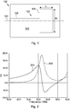
- a conventional patch antenna 100 is illustrated in figure 1 , the antenna 100 having a planar antenna structure 101 mounted on a planar substrate 102, with a ground plane (not shown) provided on the other side of the substrate 102.
- a microstrip transmission line 103 extends along an axis 104 and connects to a rectangular patch 105 extending on either side of the axis 104.
- the lateral dimensions of the rectangular patch 105 i.e. the length L and width W, along with the thickness and dielectric constant of the substrate 102, define the resonant frequency of the antenna 100, while the difference between the length and width defines the shape of the radiation pattern of the antenna 100, a smaller difference providing a more uniform pattern.
- Typical applications for patch antennas are in the field of radar sensing, which is increasingly being used in automotive applications. Frequencies of the order of tens of GHz are typically used, resulting in antenna lateral dimensions of the order of millimetres in size.
- An antenna will be designed for a particular resonant frequency and radiation pattern. Different radiation patterns, which may for example be required for narrow and wide field radar sensing, will require different antennas.
- EP 1 276 170 A1 discloses a multi-band antenna comprising a conductive patch having a feed mechanism arranged to feed electromagnetic signals to a point on a diagonal of the patch and one or more slots for manipulating the performance of the antenna.
- an antenna comprising:
- An advantage of the antenna is that the two resonant frequencies within a frequency range of operation can be used to provide different modes of operation using the same antenna. Different radiation patterns in each mode can, for example, be used to provide narrow and wide fields of view by simply switching the frequency of operation.
- the field of view of a radar system can be increased without the need for additional hardware, since a common antenna can be used for different fields of view.
- the ability to switch between different fields of view may be advantageous when a pair of antennas are oriented such that they are not in line but are oriented at an angle with respect to each other. Switching to a different beam pattern may therefore potentially increase the gain for the communication chain.
- the two resonant frequencies may be within a frequency range of 60 to 90 GHz, typically used for radar applications, and may be within a range of 75 to 110 GHz (known as the W band), or more narrowly between 77 and 81 GHz (known as the 79 GHz band, and currently the subject of development for automotive radar applications).
- a higher one of the two resonant frequencies may be less than 5% greater than a lower one of the two resonant frequencies.
- a ratio between the higher and lower resonant frequencies may be between 1.01 and 1.05, with a particular value of around 1.02. In general, a percentage difference between the resonant frequencies will be greater at lower frequencies.
- the two slots may be oriented parallel to the central symmetry axis of the patch antenna.
- Each of the two slots may be positioned between 5% and 20% of a width of the radiating element from an edge thereof, where the width of the radiating element is the linear dimension orthogonal to the central axis and in the plane of the substrate.
- the length of the rectangular inner region is the linear dimension parallel to the central axis and in the plane of the substrate.
- a width of each of the two slots may be between 0.05 and 0.3 mm.
- a radar or RF communication transceiver comprising an antenna according to the first aspect.
- a radar transceiver of the second aspect comprising:
- Figure 2 illustrates a plot of the real 201 and imaginary 202 parts of the port impedance as a function of frequency for a typical patch antenna of the type illustrated in figure 1 .
- the resonant frequency of around 77 GHz is typical for use in automotive radar sensing applications, for example as used in the Qorivva MPC577xK MCU and the MR2001 77 GHz radar transceiver chipsets available from NXP USA Inc. (previously Freescale Semiconductor, Inc.).
- the antenna is operable only at or near the single resonant frequency.
- Typical dimensions of an antenna of the type shown in figure 2 are of the order of half the wavelength of the frequency of operation.
- the length L of the patch antenna 105 may be around 1 to 2 mm for operating frequencies within the range of 75 to 150 GHz.
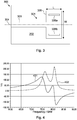
- FIG 3 is a schematic plan view of an example of an antenna 300 configured to have two resonant frequencies within a frequency range of operation.
- the antenna 300 has the same basic structure of the antenna 100 of figure 1 , i.e. with a rectangular patch antenna 301 on a substrate 302, with a microstrip lead 303 connected to a patch 305, the lead 303 extending along a central axis 304 and the patch 305 extending either side of the axis 303.
- the dimensions L and W of the patch are the same as those in the specific example provided above.
- the antenna 300 differs from the antenna 100 of figure 1 in that two slots 306a, 306b are provided within the rectangular patch 305 on opposing sides of the axis 304.
- the slots 306a, 306b result in the patch 305 having two resonant frequencies, one of which is defined by the length L of the patch and the other by the size and position of the slots 306a, 306b.
- the patch antenna is preferably symmetric about the axis 303.
- the slots 306a, 306b may be between 0.6 and 0.9 of the length L of the patch antenna 305, and in the example shown are each 0.85 mm in length.
- the slots 306a, 306b may be positioned such that each slot is between 5% and 20% of the width from the edge of the patch 305, and in the example shown are 0.2 mm from the edges.
- the slots 306a, 306b may be generally positioned to be equidistant from the edges orthogonal to the central axis 304 and are generally symmetrical about the axis 304.
- the width of each slot may be generally between 0.05 and 0.3 mm, depending on the overall dimensions of the patch and on manufacturing tolerances.
- FIG 4 A plot of the real 401 and imaginary 402 parts of the port impedance of an antenna of the type shown in figure 3 as a function of frequency is shown in figure 4 .
- the antenna 300 exhibits two resonant frequencies, in this example at around 76 GHz and 81 GHz.
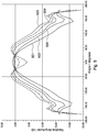
- the radiation pattern at the two resonant frequencies is different. This is illustrated in figure 5 , in which amplitude as a function of angle is plotted for different frequencies.
- the frequencies chosen for this example are 76, 77, 79, 80 and 81 GHz, covering both of the resonant frequencies exhibited by the antenna.
- the trace 501 for 76 GHz which is at the lower of the two resonant frequencies, shows a peak amplitude at zero angle, with the amplitude tailing off in either direction.
- the peak As the frequency is increased to 77 GHz (trace 502), the peak lowers and the width broadens and then, at 79 GHz (trace 503), transforms into a broader distribution with a double peak and lower amplitude at zero angle.
- 80 GHz (trace 504) and 81 GHz (trace 505) the double peak disappears but the distribution remains broader than at 76 GHz.
- the difference in radiation distribution at different frequencies can be used to define a narrow field of view at one frequency, such as at 77 GHz in the example in figure 5 , and a broader field of view at another frequency, for example using one of the higher frequencies.
- the amplitude difference at higher angles can be substantial, providing up to around 8dB difference at a 100 degree angle (i.e. the difference between the amplitudes of traces 503 and 501 at 100 degrees in figure 5 ).
- An application of this is in automotive radar sensing applications, where a narrow field of view is needed for sensing objects immediately in front of the vehicle, such as the vehicle in front, and a wider field of view for sensing objects in the surroundings, such as other vehicles and pedestrians on either side of the vehicle. Allowing for both fields of view to be possible with a single antenna reduces the amount of hardware required, and allows the field of view to be switched simply by switching the operating frequency of the antenna.
- FIG. 6 is a schematic plan view of an example antenna 600 comprising a patch antenna 601 of similar form to the antenna 300 of figure 3 , the main difference being a narrowed region 607 of the microstrip lead 603 leading to the patch antenna 601.
- the narrowed region is an example of an impedance matching network for the antenna 601.
- a matching network may be provided in other forms.
- the antenna 600 is otherwise of the same form as the antenna 300 of figure 3 , with two slots 606a, 606b on either side of a central axis 604, the patch antenna 601 and microstrip lead 603 being formed on a dielectric substrate 602 having a ground plane (not shown) on an opposing face.
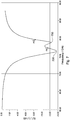
- Figure 7 shows a plot of the magnitude of the S(1,1) parameter of the antenna of figure 6 as a function of frequency, in which a first resonant frequency 701 at around 76.5 GHz and a second resonant frequency 702 at around 79 GHz are shown.
- Figures 8 and 9 illustrate further plots of amplitude as a function of angle for two different narrower frequency ranges for the same antenna.
- Figure 8 shows the variation in radiation pattern for frequencies ranging from 76 to 76.6 GHz (four traces covering a bandwidth of 0.6 GHz), while figure 9 shows the variation in radiation pattern for frequencies ranging from 78.2 to 79.6 GHz (8 traces covering a bandwidth of 1.2 GHz).
- the overall shape of the radiation pattern is distinctly different for the two frequency ranges, with the lower range having a narrower distribution with a single peak at zero angle, while the higher range has a broader distribution with peaks at around +/- 45 degrees.
- the antenna may be configured such that a radiation pattern of the antenna at a first one of the resonant frequencies has a peak at zero azimuth angle, and a radiation pattern of the antenna at a second one of the resonant frequencies has two peaks on either side of the zero azimuth angle.
- the two peaks may be at between +/- 30 to 60 degrees, and may be between +/- 40 to 50 degrees. Having peaks in the radiation pattern on either side of the zero azimuth angle broadens out the radiation pattern, thereby allowing the second resonant frequency to be used to measuring at wide angles, while the first resonant frequency can be used for measuring at narrower angles.
- the antenna thereby serves two purpose simply by changing the frequency of operation.
- FIG 10 shows a schematic plan view of an example patch antenna structure 1005, in which the length and position of the slots 1006a, 1006b are indicated. Each slot has a length L sl0t along the direction of the central axis of symmetry 1004 and an offset Off from the edge of the patch antenna 1005.
- Figures 11 and 12 are plots of real and imaginary parts of the Z(1,1) parameter of the patch antenna 1005 as a function of frequency for two values of L sl0t ( figure 11 ) and for two values of Off ( figure 12 ), illustrating the effect of changing these dimensions on the resonant frequencies.
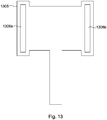
- FIG. 13 illustrates an example patch antenna structure 1305 in accordance with the invention, in which slots 1306a, 1306b are provided within loops extending outside an inner region of the patch antenna.
- the patch antenna structure 1305 is otherwise of similar general form as in the other illustrated examples.
Landscapes
- Engineering & Computer Science (AREA)
- Computer Security & Cryptography (AREA)
- Radar, Positioning & Navigation (AREA)
- Remote Sensing (AREA)
- Radar Systems Or Details Thereof (AREA)
- Waveguide Aerials (AREA)
Claims (10)
- Antenne comprenant :un substrat ;un plan de masse sur une première face du substrat ; etune antenne patch (1305) sur une seconde face opposée du substrat, l'antenne patch ayant un élément rayonnant et un conducteur s'étendant le long d'un axe de symétrie central de l'antenne patch et connecté à l'élément rayonnant,l'élément rayonnant comprenant une région rectangulaire intérieure et deux fentes (1306a, 1306b) positionnées à l'extérieur de la région rectangulaire intérieure et sur des côtés opposés de l'axe de symétrie central de telle sorte que l'antenne patch a deux fréquences de résonance dans une gamme de fréquences de fonctionnement de l'antenne patchla région rectangulaire intérieure ayant la même longueur le long de l'axe de symétrie central que l'élément rayonnant,caractérisé en ce que les deux fentes (1306a, 1306b) sont prévues dans des boucles respectives ayant chacune une longueur le long de l'axe de symétrie central qui est plus longue que la longueur de la région rectangulaire intérieure et chacune des deux fentes (1306a, 1306b) ayant une longueur plus longue que la longueur de la région rectangulaire intérieure.
- Antenne selon la revendication 1, les deux fréquences de résonance se situant dans une gamme de fréquences de 60 à 90 GHz.
- Antenne selon la revendication 2, les deux fréquences de résonance se situant dans une gamme de fréquences de 75 à 80 GHz.
- Antenne selon l'une quelconque des revendications précédentes, une fréquence de résonance supérieure parmi les deux fréquences de résonance étant supérieure de moins de 5 % à une fréquence de résonance inférieure parmi les deux fréquences de résonance.
- Antenne selon la revendication 4, le rapport entre les fréquences de résonance supérieures et inférieures étant compris entre 1,01 et 1,05.
- Antenne selon l'une quelconque des revendications précédentes, les deux fentes étant orientées parallèlement à l'axe de symétrie central.
- Antenne selon la revendication 6, chacune des deux fentes étant positionnée entre 5 % et 20 % d'une largeur de l'élément rayonnant à partir d'un bord de celui-ci.
- Antenne selon la revendication 1, une largeur de chacune des deux fentes étant comprise entre 0,05 et 0,3 mm.
- Émetteur-récepteur de communication radar ou RF comprenant une antenne selon l'une quelconque des revendications précédentes.
- Procédé de fonctionnement d'un émetteur-récepteur radar selon la revendication 9, le procédé comprenant :dans une première opération, le fonctionnement de l'émetteur-récepteur radar à une première fréquence de résonance de l'antenne pour détecter des objets dans un premier champ de vision ;dans une seconde opération, le fonctionnement de l'émetteur-récepteur radar à une seconde fréquence de résonance de l'antenne pour détecter des objets dans un second champ de vision ; etla combinaison des résultats des première et seconde opérations.
Priority Applications (2)
| Application Number | Priority Date | Filing Date | Title |
|---|---|---|---|
| EP16207490.0A EP3343697B1 (fr) | 2016-12-30 | 2016-12-30 | Antenne patch |
| US15/849,753 US11322847B2 (en) | 2016-12-30 | 2017-12-21 | Patch antenna |
Applications Claiming Priority (1)
| Application Number | Priority Date | Filing Date | Title |
|---|---|---|---|
| EP16207490.0A EP3343697B1 (fr) | 2016-12-30 | 2016-12-30 | Antenne patch |
Publications (2)
| Publication Number | Publication Date |
|---|---|
| EP3343697A1 EP3343697A1 (fr) | 2018-07-04 |
| EP3343697B1 true EP3343697B1 (fr) | 2020-08-12 |
Family
ID=57629502
Family Applications (1)
| Application Number | Title | Priority Date | Filing Date |
|---|---|---|---|
| EP16207490.0A Active EP3343697B1 (fr) | 2016-12-30 | 2016-12-30 | Antenne patch |
Country Status (2)
| Country | Link |
|---|---|
| US (1) | US11322847B2 (fr) |
| EP (1) | EP3343697B1 (fr) |
Families Citing this family (5)
| Publication number | Priority date | Publication date | Assignee | Title |
|---|---|---|---|---|
| EP3565059B1 (fr) * | 2018-04-30 | 2021-04-07 | NXP USA, Inc. | Antenne à diagramme de faisceau commutable |
| JP2020028077A (ja) * | 2018-08-16 | 2020-02-20 | 株式会社デンソーテン | アンテナ装置 |
| CN109149087B (zh) * | 2018-08-22 | 2020-10-09 | 广东工业大学 | 一种低剖面高增益超宽带天线 |
| US10868354B1 (en) * | 2019-01-17 | 2020-12-15 | Airgain, Inc. | 5G broadband antenna |
| CN116613531A (zh) * | 2023-05-30 | 2023-08-18 | 西安空间无线电技术研究所 | 一种微3d打印紧凑型毫米波天线及阵列 |
Family Cites Families (8)
| Publication number | Priority date | Publication date | Assignee | Title |
|---|---|---|---|---|
| US3403394A (en) * | 1966-07-19 | 1968-09-24 | Gen Electric | Diversity radar system |
| DE60122698T2 (de) * | 2001-07-12 | 2007-08-30 | Tdk Corp. | Mehrbandantenne |
| US6774853B2 (en) * | 2002-11-07 | 2004-08-10 | Accton Technology Corporation | Dual-band planar monopole antenna with a U-shaped slot |
| US7876274B2 (en) * | 2007-06-21 | 2011-01-25 | Apple Inc. | Wireless handheld electronic device |
| TWI491104B (zh) | 2011-12-26 | 2015-07-01 | 巽晨國際股份有限公司 | 具雙輻射場型之天線裝置 |
| US9954285B2 (en) * | 2014-09-12 | 2018-04-24 | Taoglas Group Holdings Limited | WiFi patch antenna with dual u-shaped slots |
| US10573959B2 (en) * | 2016-04-25 | 2020-02-25 | Uhnder, Inc. | Vehicle radar system using shaped antenna patterns |
| US10699305B2 (en) * | 2016-11-21 | 2020-06-30 | Nio Usa, Inc. | Smart refill assistant for electric vehicles |
-
2016
- 2016-12-30 EP EP16207490.0A patent/EP3343697B1/fr active Active
-
2017
- 2017-12-21 US US15/849,753 patent/US11322847B2/en active Active
Non-Patent Citations (4)
| Title |
|---|
| ALSALEH ADEL A A ET AL: "Design and Optimization of Dual Band Microstip Patch Antenna Using Slots Pair", 2016 INTERNATIONAL CONFERENCE ON COMPUTER AND COMMUNICATION ENGINEERING (ICCCE), IEEE, 26 July 2016 (2016-07-26), pages 439 - 442, XP033038738, DOI: 10.1109/ICCCE.2016.98 * |
| AMIT SINGH BHADOURIA ET AL: "Microstrip X-band Antenna with Improvement in Performance Using DGS", ELECTRICAL AND ELECTRONIC ENGINEERING, vol. 4, no. 2, 31 December 2014 (2014-12-31), pages 31 - 35, XP055611371, ISSN: 2162-9455, DOI: 10.5923/j.eee.20140402.02 * |
| M M SHAFIEI ET AL: "Antenna tackles wifi and wmax", MICROWAVES AND RF, 16 January 2016 (2016-01-16), pages 80 - 83, XP055611010, Retrieved from the Internet <URL:https://www.mwrf.com/sites/mwrf.com/files/datasheets/gated/Dual_Band_Antenna.pdf> [retrieved on 20190805] * |
| WEN-CHENG TZOU ET AL: "Bandwidth enhancement of U-slot patch antenna on high permittivity ceramic substrate for Bluetooth application", MICROWAVE AND OPTICAL TECHNOLOGY LETTERS, vol. 36, no. 6, 20 March 2003 (2003-03-20), US, pages 499 - 501, XP055611007, ISSN: 0895-2477, DOI: 10.1002/mop.10802 * |
Also Published As
| Publication number | Publication date |
|---|---|
| EP3343697A1 (fr) | 2018-07-04 |
| US20180198210A1 (en) | 2018-07-12 |
| US11322847B2 (en) | 2022-05-03 |
Similar Documents
| Publication | Publication Date | Title |
|---|---|---|
| EP3343697B1 (fr) | Antenne patch | |
| US9368881B2 (en) | Antenna for a radar detector | |
| CN109428150A (zh) | 天线部件、车载雷达和汽车 | |
| CN109193177A (zh) | 一种车载77GHz毫米波雷达天线 | |
| Kumar et al. | Analysis of a low-profile, dual band patch antenna for wireless applications. | |
| US11967768B2 (en) | Slot array antenna | |
| Kumar Deb et al. | Dual band multilayer E-shape microstrip patch antenna for C-band and X-band | |
| Kadam et al. | Slit loaded circular ultra wideband antenna for band notch characteristics | |
| Fei et al. | Design of a wideband dual-element slot loop antenna array with adjustable back-reflector | |
| Dhanaraj et al. | Performance analysis of electrically coupled SRR bowtie antenna for wireless broadband communications | |
| Shi et al. | A new UWB antenna with band-notched characteristic | |
| CN103078182B (zh) | 一种宽带背腔式微波毫米波圆极化天线 | |
| WO2011078293A1 (fr) | Étiquette rfid | |
| CN105337029A (zh) | 微带天线 | |
| Babu et al. | Flared V-shape slotted monopole multiband antenna with metamaterial loading | |
| CN106229644B (zh) | 一种多频太赫兹缝隙天线及其制备方法和用途 | |
| Meenu et al. | Experimental investigations on monopole loop antenna with dual band characteristics | |
| Abdulhameed et al. | Increasing radiation power in half width microstrip leaky wave antenna by using slots technique | |
| CN109428175A (zh) | 天线部件、车载雷达和汽车 | |
| Jose et al. | Emerging trends in high gain antennas for wireless communication | |
| CN107134644A (zh) | 双层微带脊型间隙波导馈电的高增益me极子天线 | |
| CN111224236A (zh) | 一种宽带圆极化微带天线阵 | |
| Tiwari et al. | Design of a Compact Antenna using Particle Swarm Optimization for the Entire Milli-meter Wave Range. | |
| Peng et al. | A novel design of broadband Quasi-Yagi antenna loaded with split-ring resonators | |
| Venkatesh et al. | Design and analysis of array of slot antenna for s-band application |
Legal Events
| Date | Code | Title | Description |
|---|---|---|---|
| PUAI | Public reference made under article 153(3) epc to a published international application that has entered the european phase |
Free format text: ORIGINAL CODE: 0009012 |
|
| STAA | Information on the status of an ep patent application or granted ep patent |
Free format text: STATUS: THE APPLICATION HAS BEEN PUBLISHED |
|
| AK | Designated contracting states |
Kind code of ref document: A1 Designated state(s): AL AT BE BG CH CY CZ DE DK EE ES FI FR GB GR HR HU IE IS IT LI LT LU LV MC MK MT NL NO PL PT RO RS SE SI SK SM TR |
|
| AX | Request for extension of the european patent |
Extension state: BA ME |
|
| STAA | Information on the status of an ep patent application or granted ep patent |
Free format text: STATUS: REQUEST FOR EXAMINATION WAS MADE |
|
| 17P | Request for examination filed |
Effective date: 20190104 |
|
| RBV | Designated contracting states (corrected) |
Designated state(s): AL AT BE BG CH CY CZ DE DK EE ES FI FR GB GR HR HU IE IS IT LI LT LU LV MC MK MT NL NO PL PT RO RS SE SI SK SM TR |
|
| STAA | Information on the status of an ep patent application or granted ep patent |
Free format text: STATUS: EXAMINATION IS IN PROGRESS |
|
| 17Q | First examination report despatched |
Effective date: 20190816 |
|
| GRAP | Despatch of communication of intention to grant a patent |
Free format text: ORIGINAL CODE: EPIDOSNIGR1 |
|
| STAA | Information on the status of an ep patent application or granted ep patent |
Free format text: STATUS: GRANT OF PATENT IS INTENDED |
|
| INTG | Intention to grant announced |
Effective date: 20200417 |
|
| RAP1 | Party data changed (applicant data changed or rights of an application transferred) |
Owner name: NXP B.V. |
|
| GRAS | Grant fee paid |
Free format text: ORIGINAL CODE: EPIDOSNIGR3 |
|
| GRAA | (expected) grant |
Free format text: ORIGINAL CODE: 0009210 |
|
| STAA | Information on the status of an ep patent application or granted ep patent |
Free format text: STATUS: THE PATENT HAS BEEN GRANTED |
|
| AK | Designated contracting states |
Kind code of ref document: B1 Designated state(s): AL AT BE BG CH CY CZ DE DK EE ES FI FR GB GR HR HU IE IS IT LI LT LU LV MC MK MT NL NO PL PT RO RS SE SI SK SM TR |
|
| REG | Reference to a national code |
Ref country code: CH Ref legal event code: EP |
|
| REG | Reference to a national code |
Ref country code: IE Ref legal event code: FG4D |
|
| REG | Reference to a national code |
Ref country code: DE Ref legal event code: R096 Ref document number: 602016041777 Country of ref document: DE |
|
| REG | Reference to a national code |
Ref country code: AT Ref legal event code: REF Ref document number: 1302457 Country of ref document: AT Kind code of ref document: T Effective date: 20200915 |
|
| REG | Reference to a national code |
Ref country code: LT Ref legal event code: MG4D |
|
| REG | Reference to a national code |
Ref country code: NL Ref legal event code: MP Effective date: 20200812 |
|
| PG25 | Lapsed in a contracting state [announced via postgrant information from national office to epo] |
Ref country code: SE Free format text: LAPSE BECAUSE OF FAILURE TO SUBMIT A TRANSLATION OF THE DESCRIPTION OR TO PAY THE FEE WITHIN THE PRESCRIBED TIME-LIMIT Effective date: 20200812 Ref country code: GR Free format text: LAPSE BECAUSE OF FAILURE TO SUBMIT A TRANSLATION OF THE DESCRIPTION OR TO PAY THE FEE WITHIN THE PRESCRIBED TIME-LIMIT Effective date: 20201113 Ref country code: FI Free format text: LAPSE BECAUSE OF FAILURE TO SUBMIT A TRANSLATION OF THE DESCRIPTION OR TO PAY THE FEE WITHIN THE PRESCRIBED TIME-LIMIT Effective date: 20200812 Ref country code: NO Free format text: LAPSE BECAUSE OF FAILURE TO SUBMIT A TRANSLATION OF THE DESCRIPTION OR TO PAY THE FEE WITHIN THE PRESCRIBED TIME-LIMIT Effective date: 20201112 Ref country code: BG Free format text: LAPSE BECAUSE OF FAILURE TO SUBMIT A TRANSLATION OF THE DESCRIPTION OR TO PAY THE FEE WITHIN THE PRESCRIBED TIME-LIMIT Effective date: 20201112 Ref country code: LT Free format text: LAPSE BECAUSE OF FAILURE TO SUBMIT A TRANSLATION OF THE DESCRIPTION OR TO PAY THE FEE WITHIN THE PRESCRIBED TIME-LIMIT Effective date: 20200812 Ref country code: HR Free format text: LAPSE BECAUSE OF FAILURE TO SUBMIT A TRANSLATION OF THE DESCRIPTION OR TO PAY THE FEE WITHIN THE PRESCRIBED TIME-LIMIT Effective date: 20200812 |
|
| REG | Reference to a national code |
Ref country code: AT Ref legal event code: MK05 Ref document number: 1302457 Country of ref document: AT Kind code of ref document: T Effective date: 20200812 |
|
| PG25 | Lapsed in a contracting state [announced via postgrant information from national office to epo] |
Ref country code: IS Free format text: LAPSE BECAUSE OF FAILURE TO SUBMIT A TRANSLATION OF THE DESCRIPTION OR TO PAY THE FEE WITHIN THE PRESCRIBED TIME-LIMIT Effective date: 20201212 Ref country code: RS Free format text: LAPSE BECAUSE OF FAILURE TO SUBMIT A TRANSLATION OF THE DESCRIPTION OR TO PAY THE FEE WITHIN THE PRESCRIBED TIME-LIMIT Effective date: 20200812 Ref country code: LV Free format text: LAPSE BECAUSE OF FAILURE TO SUBMIT A TRANSLATION OF THE DESCRIPTION OR TO PAY THE FEE WITHIN THE PRESCRIBED TIME-LIMIT Effective date: 20200812 Ref country code: PL Free format text: LAPSE BECAUSE OF FAILURE TO SUBMIT A TRANSLATION OF THE DESCRIPTION OR TO PAY THE FEE WITHIN THE PRESCRIBED TIME-LIMIT Effective date: 20200812 Ref country code: NL Free format text: LAPSE BECAUSE OF FAILURE TO SUBMIT A TRANSLATION OF THE DESCRIPTION OR TO PAY THE FEE WITHIN THE PRESCRIBED TIME-LIMIT Effective date: 20200812 |
|
| PG25 | Lapsed in a contracting state [announced via postgrant information from national office to epo] |
Ref country code: EE Free format text: LAPSE BECAUSE OF FAILURE TO SUBMIT A TRANSLATION OF THE DESCRIPTION OR TO PAY THE FEE WITHIN THE PRESCRIBED TIME-LIMIT Effective date: 20200812 Ref country code: DK Free format text: LAPSE BECAUSE OF FAILURE TO SUBMIT A TRANSLATION OF THE DESCRIPTION OR TO PAY THE FEE WITHIN THE PRESCRIBED TIME-LIMIT Effective date: 20200812 Ref country code: CZ Free format text: LAPSE BECAUSE OF FAILURE TO SUBMIT A TRANSLATION OF THE DESCRIPTION OR TO PAY THE FEE WITHIN THE PRESCRIBED TIME-LIMIT Effective date: 20200812 Ref country code: RO Free format text: LAPSE BECAUSE OF FAILURE TO SUBMIT A TRANSLATION OF THE DESCRIPTION OR TO PAY THE FEE WITHIN THE PRESCRIBED TIME-LIMIT Effective date: 20200812 Ref country code: SM Free format text: LAPSE BECAUSE OF FAILURE TO SUBMIT A TRANSLATION OF THE DESCRIPTION OR TO PAY THE FEE WITHIN THE PRESCRIBED TIME-LIMIT Effective date: 20200812 |
|
| REG | Reference to a national code |
Ref country code: DE Ref legal event code: R097 Ref document number: 602016041777 Country of ref document: DE |
|
| PG25 | Lapsed in a contracting state [announced via postgrant information from national office to epo] |
Ref country code: AT Free format text: LAPSE BECAUSE OF FAILURE TO SUBMIT A TRANSLATION OF THE DESCRIPTION OR TO PAY THE FEE WITHIN THE PRESCRIBED TIME-LIMIT Effective date: 20200812 Ref country code: AL Free format text: LAPSE BECAUSE OF FAILURE TO SUBMIT A TRANSLATION OF THE DESCRIPTION OR TO PAY THE FEE WITHIN THE PRESCRIBED TIME-LIMIT Effective date: 20200812 Ref country code: ES Free format text: LAPSE BECAUSE OF FAILURE TO SUBMIT A TRANSLATION OF THE DESCRIPTION OR TO PAY THE FEE WITHIN THE PRESCRIBED TIME-LIMIT Effective date: 20200812 |
|
| PLBE | No opposition filed within time limit |
Free format text: ORIGINAL CODE: 0009261 |
|
| STAA | Information on the status of an ep patent application or granted ep patent |
Free format text: STATUS: NO OPPOSITION FILED WITHIN TIME LIMIT |
|
| PG25 | Lapsed in a contracting state [announced via postgrant information from national office to epo] |
Ref country code: SK Free format text: LAPSE BECAUSE OF FAILURE TO SUBMIT A TRANSLATION OF THE DESCRIPTION OR TO PAY THE FEE WITHIN THE PRESCRIBED TIME-LIMIT Effective date: 20200812 |
|
| 26N | No opposition filed |
Effective date: 20210514 |
|
| PG25 | Lapsed in a contracting state [announced via postgrant information from national office to epo] |
Ref country code: IT Free format text: LAPSE BECAUSE OF FAILURE TO SUBMIT A TRANSLATION OF THE DESCRIPTION OR TO PAY THE FEE WITHIN THE PRESCRIBED TIME-LIMIT Effective date: 20200812 |
|
| REG | Reference to a national code |
Ref country code: CH Ref legal event code: PL |
|
| PG25 | Lapsed in a contracting state [announced via postgrant information from national office to epo] |
Ref country code: SI Free format text: LAPSE BECAUSE OF FAILURE TO SUBMIT A TRANSLATION OF THE DESCRIPTION OR TO PAY THE FEE WITHIN THE PRESCRIBED TIME-LIMIT Effective date: 20200812 Ref country code: MC Free format text: LAPSE BECAUSE OF FAILURE TO SUBMIT A TRANSLATION OF THE DESCRIPTION OR TO PAY THE FEE WITHIN THE PRESCRIBED TIME-LIMIT Effective date: 20200812 |
|
| REG | Reference to a national code |
Ref country code: BE Ref legal event code: MM Effective date: 20201231 |
|
| PG25 | Lapsed in a contracting state [announced via postgrant information from national office to epo] |
Ref country code: IE Free format text: LAPSE BECAUSE OF NON-PAYMENT OF DUE FEES Effective date: 20201230 Ref country code: LU Free format text: LAPSE BECAUSE OF NON-PAYMENT OF DUE FEES Effective date: 20201230 |
|
| PG25 | Lapsed in a contracting state [announced via postgrant information from national office to epo] |
Ref country code: CH Free format text: LAPSE BECAUSE OF NON-PAYMENT OF DUE FEES Effective date: 20201231 Ref country code: LI Free format text: LAPSE BECAUSE OF NON-PAYMENT OF DUE FEES Effective date: 20201231 |
|
| PG25 | Lapsed in a contracting state [announced via postgrant information from national office to epo] |
Ref country code: TR Free format text: LAPSE BECAUSE OF FAILURE TO SUBMIT A TRANSLATION OF THE DESCRIPTION OR TO PAY THE FEE WITHIN THE PRESCRIBED TIME-LIMIT Effective date: 20200812 Ref country code: MT Free format text: LAPSE BECAUSE OF FAILURE TO SUBMIT A TRANSLATION OF THE DESCRIPTION OR TO PAY THE FEE WITHIN THE PRESCRIBED TIME-LIMIT Effective date: 20200812 Ref country code: CY Free format text: LAPSE BECAUSE OF FAILURE TO SUBMIT A TRANSLATION OF THE DESCRIPTION OR TO PAY THE FEE WITHIN THE PRESCRIBED TIME-LIMIT Effective date: 20200812 |
|
| PG25 | Lapsed in a contracting state [announced via postgrant information from national office to epo] |
Ref country code: MK Free format text: LAPSE BECAUSE OF FAILURE TO SUBMIT A TRANSLATION OF THE DESCRIPTION OR TO PAY THE FEE WITHIN THE PRESCRIBED TIME-LIMIT Effective date: 20200812 |
|
| PG25 | Lapsed in a contracting state [announced via postgrant information from national office to epo] |
Ref country code: PT Free format text: LAPSE BECAUSE OF FAILURE TO SUBMIT A TRANSLATION OF THE DESCRIPTION OR TO PAY THE FEE WITHIN THE PRESCRIBED TIME-LIMIT Effective date: 20200812 Ref country code: BE Free format text: LAPSE BECAUSE OF NON-PAYMENT OF DUE FEES Effective date: 20201231 |
|
| P01 | Opt-out of the competence of the unified patent court (upc) registered |
Effective date: 20230725 |
|
| PGFP | Annual fee paid to national office [announced via postgrant information from national office to epo] |
Ref country code: DE Payment date: 20251126 Year of fee payment: 10 |
|
| PGFP | Annual fee paid to national office [announced via postgrant information from national office to epo] |
Ref country code: GB Payment date: 20251119 Year of fee payment: 10 |
|
| PGFP | Annual fee paid to national office [announced via postgrant information from national office to epo] |
Ref country code: FR Payment date: 20251120 Year of fee payment: 10 |