EP3343705A1 - Connecteur de réceptacle et unité de caméra - Google Patents
Connecteur de réceptacle et unité de caméra Download PDFInfo
- Publication number
- EP3343705A1 EP3343705A1 EP17207419.7A EP17207419A EP3343705A1 EP 3343705 A1 EP3343705 A1 EP 3343705A1 EP 17207419 A EP17207419 A EP 17207419A EP 3343705 A1 EP3343705 A1 EP 3343705A1
- Authority
- EP
- European Patent Office
- Prior art keywords
- shell
- extension direction
- connector
- spacer
- seal member
- Prior art date
- Legal status (The legal status is an assumption and is not a legal conclusion. Google has not performed a legal analysis and makes no representation as to the accuracy of the status listed.)
- Granted
Links
Images


Classifications
-
- H—ELECTRICITY
- H01—ELECTRIC ELEMENTS
- H01R—ELECTRICALLY-CONDUCTIVE CONNECTIONS; STRUCTURAL ASSOCIATIONS OF A PLURALITY OF MUTUALLY-INSULATED ELECTRICAL CONNECTING ELEMENTS; COUPLING DEVICES; CURRENT COLLECTORS
- H01R13/00—Details of coupling devices of the kinds covered by groups H01R12/70 or H01R24/00 - H01R33/00
- H01R13/40—Securing contact members in or to a base or case; Insulating of contact members
- H01R13/405—Securing in non-demountable manner, e.g. moulding, riveting
-
- H—ELECTRICITY
- H01—ELECTRIC ELEMENTS
- H01R—ELECTRICALLY-CONDUCTIVE CONNECTIONS; STRUCTURAL ASSOCIATIONS OF A PLURALITY OF MUTUALLY-INSULATED ELECTRICAL CONNECTING ELEMENTS; COUPLING DEVICES; CURRENT COLLECTORS
- H01R13/00—Details of coupling devices of the kinds covered by groups H01R12/70 or H01R24/00 - H01R33/00
- H01R13/46—Bases; Cases
-
- H—ELECTRICITY
- H01—ELECTRIC ELEMENTS
- H01R—ELECTRICALLY-CONDUCTIVE CONNECTIONS; STRUCTURAL ASSOCIATIONS OF A PLURALITY OF MUTUALLY-INSULATED ELECTRICAL CONNECTING ELEMENTS; COUPLING DEVICES; CURRENT COLLECTORS
- H01R12/00—Structural associations of a plurality of mutually-insulated electrical connecting elements, specially adapted for printed circuits, e.g. printed circuit boards [PCB], flat or ribbon cables, or like generally planar structures, e.g. terminal strips, terminal blocks; Coupling devices specially adapted for printed circuits, flat or ribbon cables, or like generally planar structures; Terminals specially adapted for contact with, or insertion into, printed circuits, flat or ribbon cables, or like generally planar structures
- H01R12/70—Coupling devices
- H01R12/71—Coupling devices for rigid printing circuits or like structures
- H01R12/712—Coupling devices for rigid printing circuits or like structures co-operating with the surface of the printed circuit or with a coupling device exclusively provided on the surface of the printed circuit
- H01R12/716—Coupling device provided on the PCB
-
- H—ELECTRICITY
- H01—ELECTRIC ELEMENTS
- H01R—ELECTRICALLY-CONDUCTIVE CONNECTIONS; STRUCTURAL ASSOCIATIONS OF A PLURALITY OF MUTUALLY-INSULATED ELECTRICAL CONNECTING ELEMENTS; COUPLING DEVICES; CURRENT COLLECTORS
- H01R13/00—Details of coupling devices of the kinds covered by groups H01R12/70 or H01R24/00 - H01R33/00
- H01R13/02—Contact members
- H01R13/04—Pins or blades for co-operation with sockets
-
- H—ELECTRICITY
- H01—ELECTRIC ELEMENTS
- H01R—ELECTRICALLY-CONDUCTIVE CONNECTIONS; STRUCTURAL ASSOCIATIONS OF A PLURALITY OF MUTUALLY-INSULATED ELECTRICAL CONNECTING ELEMENTS; COUPLING DEVICES; CURRENT COLLECTORS
- H01R13/00—Details of coupling devices of the kinds covered by groups H01R12/70 or H01R24/00 - H01R33/00
- H01R13/40—Securing contact members in or to a base or case; Insulating of contact members
- H01R13/42—Securing in a demountable manner
- H01R13/436—Securing a plurality of contact members by one locking piece or operation
- H01R13/4367—Insertion of locking piece from the rear
-
- H—ELECTRICITY
- H01—ELECTRIC ELEMENTS
- H01R—ELECTRICALLY-CONDUCTIVE CONNECTIONS; STRUCTURAL ASSOCIATIONS OF A PLURALITY OF MUTUALLY-INSULATED ELECTRICAL CONNECTING ELEMENTS; COUPLING DEVICES; CURRENT COLLECTORS
- H01R13/00—Details of coupling devices of the kinds covered by groups H01R12/70 or H01R24/00 - H01R33/00
- H01R13/46—Bases; Cases
- H01R13/502—Bases; Cases composed of different pieces
-
- H—ELECTRICITY
- H01—ELECTRIC ELEMENTS
- H01R—ELECTRICALLY-CONDUCTIVE CONNECTIONS; STRUCTURAL ASSOCIATIONS OF A PLURALITY OF MUTUALLY-INSULATED ELECTRICAL CONNECTING ELEMENTS; COUPLING DEVICES; CURRENT COLLECTORS
- H01R13/00—Details of coupling devices of the kinds covered by groups H01R12/70 or H01R24/00 - H01R33/00
- H01R13/46—Bases; Cases
- H01R13/502—Bases; Cases composed of different pieces
- H01R13/506—Bases; Cases composed of different pieces assembled by snap action of the parts
-
- H—ELECTRICITY
- H01—ELECTRIC ELEMENTS
- H01R—ELECTRICALLY-CONDUCTIVE CONNECTIONS; STRUCTURAL ASSOCIATIONS OF A PLURALITY OF MUTUALLY-INSULATED ELECTRICAL CONNECTING ELEMENTS; COUPLING DEVICES; CURRENT COLLECTORS
- H01R13/00—Details of coupling devices of the kinds covered by groups H01R12/70 or H01R24/00 - H01R33/00
- H01R13/46—Bases; Cases
- H01R13/52—Dustproof, splashproof, drip-proof, waterproof, or flameproof cases
- H01R13/5202—Sealing means between parts of housing or between housing part and a wall, e.g. sealing rings
-
- H—ELECTRICITY
- H01—ELECTRIC ELEMENTS
- H01R—ELECTRICALLY-CONDUCTIVE CONNECTIONS; STRUCTURAL ASSOCIATIONS OF A PLURALITY OF MUTUALLY-INSULATED ELECTRICAL CONNECTING ELEMENTS; COUPLING DEVICES; CURRENT COLLECTORS
- H01R13/00—Details of coupling devices of the kinds covered by groups H01R12/70 or H01R24/00 - H01R33/00
- H01R13/46—Bases; Cases
- H01R13/52—Dustproof, splashproof, drip-proof, waterproof, or flameproof cases
- H01R13/521—Sealing between contact members and housing, e.g. sealing insert
-
- H—ELECTRICITY
- H01—ELECTRIC ELEMENTS
- H01R—ELECTRICALLY-CONDUCTIVE CONNECTIONS; STRUCTURAL ASSOCIATIONS OF A PLURALITY OF MUTUALLY-INSULATED ELECTRICAL CONNECTING ELEMENTS; COUPLING DEVICES; CURRENT COLLECTORS
- H01R13/00—Details of coupling devices of the kinds covered by groups H01R12/70 or H01R24/00 - H01R33/00
- H01R13/62—Means for facilitating engagement or disengagement of coupling parts or for holding them in engagement
- H01R13/639—Additional means for holding or locking coupling parts together, after engagement, e.g. separate keylock, retainer strap
-
- H—ELECTRICITY
- H01—ELECTRIC ELEMENTS
- H01R—ELECTRICALLY-CONDUCTIVE CONNECTIONS; STRUCTURAL ASSOCIATIONS OF A PLURALITY OF MUTUALLY-INSULATED ELECTRICAL CONNECTING ELEMENTS; COUPLING DEVICES; CURRENT COLLECTORS
- H01R13/00—Details of coupling devices of the kinds covered by groups H01R12/70 or H01R24/00 - H01R33/00
- H01R13/648—Protective earth or shield arrangements on coupling devices, e.g. anti-static shielding
- H01R13/658—High frequency shielding arrangements, e.g. against EMI [Electro-Magnetic Interference] or EMP [Electro-Magnetic Pulse]
- H01R13/6591—Specific features or arrangements of connection of shield to conductive members
-
- H—ELECTRICITY
- H01—ELECTRIC ELEMENTS
- H01R—ELECTRICALLY-CONDUCTIVE CONNECTIONS; STRUCTURAL ASSOCIATIONS OF A PLURALITY OF MUTUALLY-INSULATED ELECTRICAL CONNECTING ELEMENTS; COUPLING DEVICES; CURRENT COLLECTORS
- H01R13/00—Details of coupling devices of the kinds covered by groups H01R12/70 or H01R24/00 - H01R33/00
- H01R13/648—Protective earth or shield arrangements on coupling devices, e.g. anti-static shielding
- H01R13/658—High frequency shielding arrangements, e.g. against EMI [Electro-Magnetic Interference] or EMP [Electro-Magnetic Pulse]
- H01R13/6591—Specific features or arrangements of connection of shield to conductive members
- H01R13/6594—Specific features or arrangements of connection of shield to conductive members the shield being mounted on a PCB and connected to conductive members
-
- H—ELECTRICITY
- H04—ELECTRIC COMMUNICATION TECHNIQUE
- H04N—PICTORIAL COMMUNICATION, e.g. TELEVISION
- H04N23/00—Cameras or camera modules comprising electronic image sensors; Control thereof
- H04N23/50—Constructional details
- H04N23/54—Mounting of pick-up tubes, electronic image sensors, deviation or focusing coils
-
- H—ELECTRICITY
- H01—ELECTRIC ELEMENTS
- H01R—ELECTRICALLY-CONDUCTIVE CONNECTIONS; STRUCTURAL ASSOCIATIONS OF A PLURALITY OF MUTUALLY-INSULATED ELECTRICAL CONNECTING ELEMENTS; COUPLING DEVICES; CURRENT COLLECTORS
- H01R13/00—Details of coupling devices of the kinds covered by groups H01R12/70 or H01R24/00 - H01R33/00
- H01R13/40—Securing contact members in or to a base or case; Insulating of contact members
- H01R13/405—Securing in non-demountable manner, e.g. moulding, riveting
- H01R13/41—Securing in non-demountable manner, e.g. moulding, riveting by frictional grip in grommet, panel or base
Definitions
- This kind of receptacle connector has a signal terminal with one side connected to an electronic substrate of an electronic device, and is used as an electronic substrate unit (e.g., a vehicle-mounted camera unit obtained by attaching a receptacle connector to a vehicle-mounted camera module serving as the electronic substrate) in some cases.
- an electronic substrate unit e.g., a vehicle-mounted camera unit obtained by attaching a receptacle connector to a vehicle-mounted camera module serving as the electronic substrate
- this kind of receptacle connector is sometimes used together with a plug connector connected to a connection portion on a side of the receptacle connector corresponding to the plug connector (hereinafter referred to as "plug connector side”), which is the side opposite to a side corresponding to the electronic substrate (hereinafter referred to as “electronic substrate side”), to form a pair of connectors.
- plug connector side a plug connector connected to a connection portion on a side of the receptacle connector corresponding to the plug connector
- electro substrate side the side opposite to a side corresponding to the electronic substrate
- Examples of added functions include a waterproofing function, ease of attaching an electronic substrate including an electronic circuit (hereinafter referred to as “mountability"), an ability of shielding the electronic circuit from noise, ease of assembly, and safety during use.
- the holder is in a state of holding the signal terminals at the center portion in the extension direction of the signal terminals (i.e., a state in which both end portions of the signal terminals are exposed). Also, the holder is covered by the first shell due to being inserted into the tube of the first shell or the like, for example, while holding the signal terminals.
- the signal terminals when held by the holder, overlap with the portion of the tube of the conductive first shell in a view in the radial direction of the signal terminals, and the signal terminals are shielded from electrical noise (electromagnetic waves) from the radial direction at the overlapping portion.
- the signal terminals and the holder are contained in the connector case via the first shell and function as the receptacle connector.
- the surface portion of the spacer can be used to mount the electronic substrate for forming the camera unit on the receptacle connector, for example.
- the electronic substrate can be easily mounted on the receptacle connector due to the surface portion of the spacer.
- a receptacle connector that includes an added function of being able to provide high safety by reliably positioning the holder and the signal terminals so as to avoid a case in which the positions of the signal terminals shift during use (e.g., avoid an accident such as short-circuiting), with a simple structure in which the above-described spacer is used to engage the signal terminals, the holder, and the first shell to each other as described above.
- a further characteristic configuration of a receptacle connector according to an embodiment of the present invention lies in including a second shell having a conducting bottom portion including an opening portion through which the first shell penetrates, wherein the spacer is arranged on the electronic substrate side with respect to the second shell, and the second shell is interposed between the spacer and the connector case with the second shell being penetrated by the first shell at the opening portion, and thus the second shell is restricted from moving in the extension direction.
- the second shell penetrates through the first shell at its opening portion, and therefore the second shell intersects with the extension direction of the signal terminals. Accordingly, the bottom portion of the conductive second shell functions so as to block electrical noise in the extension direction. Also, the second shell having this noise blocking ability can be attached to the receptacle connector using a simple structure and assembly method in which the second shell is interposed between the spacer and the connector case.
- a receptacle connector with a simple structure including added functions such as a noise blocking ability and ease of assembly.
- a further characteristic configuration of a receptacle connector according to an embodiment of the present invention lies in that the surface portion includes a spacer wall that is bent from the periphery of the surface portion and extends to the plug connector side in the extension direction, and an end portion of the spacer wall on the plug connector side locks the second shell from the electronic substrate side and restricts movement of the second shell in the extension direction.
- the second shell is locked by the end portion of the spacer wall on the plug connector side, and thus it is possible to prevent movement of the second shell in the extension direction, or in other words, movement thereof toward the plug connector side, and the second shell can be prevented from falling off from the electronic substrate side with a simple configuration.
- a further characteristic configuration of a receptacle connector according to an embodiment of the present invention lies in that a circular ring-shaped outer seal member that seals a gap between the first shell and the connector case in the extension direction is included on an outer side of the first shell in the radial direction, and the outer seal member is interposed between the bottom portion and the connector case and thus the outer seal member is restricted from moving in the extension direction.
- the gap between the inner circumferential surface of the connector case and the first shell is sealed by the outer seal member, and thus it is possible to provide a waterproofing function of preventing water from entering the electronic substrate side from the plug connector side.
- the mounting of the outer seal member can be made reliable using a mode in which the outer seal member is interposed between the bottom portion of the second shell and the connector case, or in other words, with a simple and easily-assembled structure in which the outer seal member is locked from the electronic substrate side to the plug connector side by the bottom portion of the second shell.
- a further characteristic configuration of a receptacle connector according to an embodiment of the present invention lies in that a circular column-shaped inner seal member that seals the interior of the first shell in the extension direction is included on an inner side of the first shell in the radial direction, and the inner seal member is interposed between the spacer and the holder, and thus the inner seal member is restricted from moving in the extension direction.
- the gap between the first shell and the inner seal member is sealed by the inner seal member, and it is possible to provide a waterproofing function of preventing water from entering the electronic substrate side from the plug connector side (waterproofing). Also, the mounting of the inner seal member can be made more reliable with a simple and easily-assembled structure in which the inner seal member is interposed between the spacer and the holder.
- the surface of the inner seal member on the electronic substrate side is locked by the support portion, whereby it is possible to prevent the inner seal member from moving to the electronic substrate side.
- a case in which the inner seal member falls off from the electronic substrate side can be avoided with a simple structure.
- a further characteristic configuration of a receptacle connector according to an embodiment of the present invention lies in that the support portion of the spacer protrudes in the form of a circular column from the surface portion to the plug connector side in the extension direction.
- mounting of the inner seal member can be made reliable in a state of arrangement in which the inner seal member is pressed to the inner side (inner portion) of the tube of the first shell by the support portion.
- the positioning of the signal terminals can be made reliable by increasing the lengths in the extension direction of the insertion holes provided in the support portion.
- a characteristic configuration of a camera unit for achieving the above-described object lies in including an electronic substrate including: an image sensor; an electronic circuit that performs driving control for the image sensor and that processes an image signal output from the image sensor; and an optical system having a lens that focuses light on the image sensor; and the receptacle connector described above, wherein the electronic circuit is electrically connected to the signal terminals and the electronic substrate is mounted on the surface portion of the spacer.
- a camera unit including added functions such as high safety, a noise blocking ability, ease of assembly, and a waterproofing ability can be provided with a simple configuration in which the electronic substrate is mounted on the surface portion of the spacer.
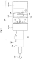
- FIGS. 1 to 9 A receptacle connector and a connector according to an embodiment of the present invention will be described with reference to FIGS. 1 to 9 .
- the present embodiment describes, as an example, a receptacle connector 10 that is to be attached to a camera module 110 serving as an example of an electronic substrate, and that is to be used in a camera unit 100 (e.g., a vehicle-mounted camera to be installed in a car) that is to be mounted in a vehicle (not shown).
- a camera unit 100 e.g., a vehicle-mounted camera to be installed in a car
- the connector 20 is used to electrically connect a cable 130 connected to the plug connector 120 and the camera module 110.
- the connector 20 outputs signals from the cable 130 to the camera module 110 (see FIG. 1 ) and outputs signals from the camera module 110 to the cable 130. Furthermore, the power for driving that is supplied from the cable 130 is supplied to the camera module 110.
- signals transmitted by the cable 130 include signals for controlling the camera module 110 and image signals including image information received from the camera module 110.
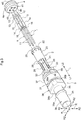
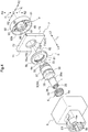
- the receptacle connector 10 includes: four linear signal terminals 1 that can fit together with the plug connector 120 (see FIG. 7 ) in an extension direction L and transmit signals between the plug connector side L1 and an electronic substrate side L2; an insulating holder 2 that has a circular column shape extending in the extension direction L, and that holds the signal terminals 1 by being penetrated by them in the extension direction L; a conductive first shell 3 having a tube shape that covers the outer circumference of the holder 2 in a radial direction R that is orthogonal to the extension direction L; and a non-conductive connector case 8 that includes a cylindrical space E3 that extends in the extension direction L and contains the first shell 3.
- FIG. 2 shows a cross-section taken along the extension direction L of the receptacle connector 10.
- the receptacle connector 10 further includes: an inner seal member 4 that seals the interior of the first shell 3 in the extension direction L; and an outer seal member 6 that seals the interior of the cylindrical space E3 in the extension direction L, and thus water is prevented from entering the electronic substrate side L2 from the plug connector side L1 (hereinafter referred to as "waterproofing").
- waterproofing By thus including the waterproofing function, it is possible to prevent accidents such as short-circuiting, for example, and thus high safety can be provided.
- the receptacle connector 10 includes a second shell 7, which is an electrical protection member that covers the electronic substrate side L2 of the receptacle connector 10 so as to shield and protect it from electrical noise (electromagnetic waves) oriented from mainly the plug connector side L1 to the electronic substrate side L2 of the outer space E1, and a spacer 9 for mounting the camera module 110.
- a second shell 7 is an electrical protection member that covers the electronic substrate side L2 of the receptacle connector 10 so as to shield and protect it from electrical noise (electromagnetic waves) oriented from mainly the plug connector side L1 to the electronic substrate side L2 of the outer space E1, and a spacer 9 for mounting the camera module 110.
- the connector case 8 includes a cylindrical space E3 partitioned by an inner circumferential surface 8a, and a space E2.
- the connector case 8 is a container for the receptacle connector 10 that contains a terminal module 30 composed of the first shell 3 in the cylindrical space E3, and into which the plug connector 120 is inserted.
- terminal module 30 refers to a module obtained by assembling the holder 2 holding the signal terminal 1 and the inner seal member 4 in the first shell 3.
- the connector case 8 is formed of an insulating (non-conductive) material such as resin. The purpose of this is to insulate the signal terminal 1, the first shell 3, and the second shell 7 from the exterior of the receptacle connector 10 because the signal terminal 1, the first shell 3, and the second shell 7 are conductive.
- the connector case 8 is made of resin
- the connector case 8 can be formed of nylon, polypropylene, polyphenylene sulfide resin, vinyl chloride resin, or the like, and the present embodiment indicates a case of being formed of nylon as one embodiment.
- the connector case 8 includes first engagement hooks 81 and an outer seal contact surface 86 on the inner circumferential surface 8a of the connector case 8 that forms the cylindrical space E3 (see FIG. 6 ).
- the first engagement hooks 81 are multiple (in the present embodiment, four) hook-shaped protrusions that protrude to an inner side R1 in the radial direction R from the inner circumferential surface 8a and have elastic forces along the radial direction R.
- the first engagement hooks 81 engage with later-described first engagement recessed portions 31, which are groove-shaped recessed portions of the first shell 3 and lock the first shell 3 (terminal module 30) in the cylindrical space E3.
- Jutting portions 83 that slightly protrude from the inner circumferential surface 8a to the inner side R1 in the radial direction R are provided between respective adjacent first engagement hooks 81 of the connector case 8 (see FIG. 6 ).
- the outer seal contact surface 86 is a surface provided on the inner circumferential surface 8a of the connector case 8 and is provided as a surface that intersects the extension direction L and opposes the space E2 (a surface that faces the electronic substrate side L2). In the present embodiment, the outer seal contact surface 86 is orthogonal to the extension direction L in one mode of intersecting. The outer seal member 6 comes into contact with the outer seal contact surface 86.
- the connector case 8 includes protrusions 85 and a ring-shaped extension portion 82, for example, as members that support the second shell 7 when the second shell 7 is contained in the space E2 (see FIG. 6 ).
- the ring-shaped extension portion 82 supports a bottom portion 71 of the second shell 7 toward the electronic substrate side L2, and the protrusions 85 support the second shell 7 relatively from the sides with respect to the extension direction L.
- the protrusions 85 are provided in a mode of protruding from the inner circumferential surface 8a to the inner side R1 in the radial direction R, for example.
- the ring-shaped extension portion 82 extends in the extension direction L from the connector case 8, for example, and is provided as a ring-shaped member that extends to the electronic substrate side L2.
- the connector case 8 includes a retaining reception portion 88 that engages with a retaining pin of the plug connector 120 and prevents separation of the plug connector 120 from the connector case 8.
- the connector case 8 sometimes includes a main body case 89, which is a case that covers the electronic substrate side L2 of the receptacle connector 10 and contains the camera module 110 when the receptacle connector 10 is attached to the camera module 110 and is used as the camera unit 100.
- a main body case 89 which is a case that covers the electronic substrate side L2 of the receptacle connector 10 and contains the camera module 110 when the receptacle connector 10 is attached to the camera module 110 and is used as the camera unit 100.
- the signal terminals 1 are members that transmit at least signals between the cable 130 (see FIG. 7 ) connected from the plug connector side L1 and the camera module 110 connected to the electronic substrate side L2.
- the signal terminals 1 correspond to the inner conductor of the cable 130.
- the diameters of the signal terminals 1 are 0.3 mm to 5 mm, for example. In the case of using the receptacle connector 10 with the camera module 110, the diameters of the signal terminals 1 are typically 0.3 mm to 1.5 mm.
- the signal terminals 1 each further include a first bulging portion 13, a second bulging portion 14, an adjustment portion 15, and a retaining protrusion 16 (see FIG. 3 ).
- the second terminal portion 12 is arranged in a state in which the leading end portion extends (protrudes) from the spacer 9 to the electronic substrate side L2.
- the purpose of this is to electrically connect to the camera module 110.
- the first bulging portion 13 and the second bulging portion 14 are portions of the signal terminal 1 that are formed so as to be relatively thicker than the first terminal portion 11 and the second terminal portion 12 respectively.
- the adjustment portion 15 is a portion of the signal terminal 1 that is formed so as to be relatively thicker than the first terminal portion 11 or the second terminal portion 12 and to be relatively thinner than the first bulging portion 13.
- the retaining protrusion 16 is a protrusion that is provided at a position shifted toward the electronic substrate side L2 of the first terminal portion 11 (the approximate central portion of the signal terminal 1, in the vicinity of the plug connector side L1 of the second bulging portion 14).
- the diameter of the signal terminal 1 refers to the diameter of the first terminal portion 11 or the second terminal portion 12.
- the second bulging portion 14 is a portion that is supported by the inner seal member 4 by being inserted through the inner seal member 4.
- the characteristic impedance of the receptacle connector 10 decreases. Conversely, if the diameter of the signal terminal 1 decreases, the characteristic impedance of the receptacle connector 10 increases.
- the characteristic impedance of the receptacle connector 10 decreases. Conversely, if the diameters of the first bulging portion 13 and the adjustment portion 15 decrease, the characteristic impedance of the receptacle connector 10 increases.
- the characteristic impedance of the receptacle connector 10 will increase. Conversely, when the length of the adjustment portion 15 is reduced (when the length of the first bulging portion 13 is increased), the characteristic impedance of the receptacle connector 10 will decrease.
- the holder 2 is an insulator that covers the signal terminals 1 and corresponds to the insulator of the cable 130.
- the holder 2 is formed of resin serving as an insulator.
- resin for example, nylon resin, vinyl chloride resin, polyethylene resin, or the like can be used as the resin.
- the holder 2 is a holding member that accurately positions and holds the signal terminals 1 due to the signal terminals 1 being inserted so as to penetrate through holding holes 29 (see FIG. 3 ).
- the holding holes 29 are holes that extend in the extension direction L.
- one signal terminal 1 is allocated to one holding hole 29.
- the holder 2 includes the same number of holding holes 29 as signal terminals 1.
- the holder 2 has a column shape that extends in the extension direction L, and includes a circular column-shaped body portion 23 that is the main body portion of the holder 2, a locking portion 25 that is arranged on the end portion on the electronic substrate side L2 of the body portion 23 and is relatively thicker than the body portion 23 (the diameter in the radial direction R that is orthogonal to the extension direction L is larger), holding holes 29 that are holes that extend in the extension direction L, and leg portions 28 that serve as three-dimensional barriers for the plug connector 120 and determine the insertion state of the plug connector 120.
- the leg portions 28 are members that extend in the form of columns along the extension direction L from the body portion 23 toward the plug connector side L1. As will be described later, the leg portions 28 are positioning portions that determine mutual insertion positions in the case where the plug connector 120 is inserted into and fit into the receptacle connector 10.
- the first terminal portions 11 of the signal terminals 1 are inserted into the holding holes 29 of the holder 2.
- the retaining protrusions 16 of the first terminal portions 11 are press-fit into the holding holes 29 from the electronic substrate side L2 of the holder 2, the holding holes 29 and the retaining protrusions 16 are engaged, and the signal terminals 1 are fixed to the holder 2.
- the diameters of the holding holes 29 are formed to be the same as or slightly larger than the diameters of the signal terminals 1. Also, the diameters of the holding holes 29 are slightly smaller than the diameters of the portions of the retaining protrusions 16. This is done to enable the first terminal portions 11 of the signal terminals 1 to be inserted through the holding holes 29 without strain and to prevent the signal terminals 1 from easily falling off in the case where the retaining protrusions 16 of the first terminal portions 11 are press-fit into the holding holes 29.
- the insertion positions of the signal terminals 1 in the holder 2 are determined due to the end portions on the plug connector side L1 of the second bulging portions 14 being locked at the opening portions on the electronic substrate side L2 of the holding holes 29. That is, the holder 2 holds the portions on the electronic substrate side of the first terminal portions 11 of the signal terminals 1, or in other words, the approximate central portions of the signal terminals 1 in the holding holes 29. That is, the leading end portions on the plug connector side L1 of the first terminal portions 11 are not covered by the holder 2, but penetrate through and are exposed from the holder 2 to serve as terminal portions.
- the holder 2 includes multiple (in the present embodiment, four) holding holes 29, which are holes that extend in the extension direction L in the body portion 23, and one signal terminal 1 is accurately positioned and held by one holding hole 29.
- leg portions 28 are provided between some of the adjacent signal terminals 1. In the present embodiment, the leg portions 28 are provided between three of the four signal terminals 1.
- the first shell 3 is a member that covers the outer circumferential side in the radial direction R of the holder 2.
- the first shell 3 is a member that corresponds to the outer conductor of the cable 130 and is an electrical protection member that protects the signal terminal 1 from electrical noise from the outer space E1.
- the first shell 3 includes a body portion 38 serving as a main body portion of the first shell 3, and the body portion 38 includes, in order from the plug connector side L1 to the electronic substrate side L2, a polyhedron portion 36, a first engagement recessed portion 31 that is a groove-shaped recessed portion, a connection portion 37, and a second engagement recessed portion 39 that is a groove-shaped recessed portion.
- Leading-end protrusions 33 see FIGS. 3 and 5
- engagement grooves 34 are provided on the leading end on the electronic substrate side L2 of the body portion 38 (see FIG. 3 ).
- the first shell 3 is used as an electrical protection member and is formed of a material that shields electrical noise.
- materials that block electrical noise include resin compounds with a metal or a metal powder kneaded in, resin with metal plating, and the like.
- the first shell 3 is formed of copper serving as a metal, and the surface thereof is plated with tin serving as a metal.
- the tin plating also prevents rusting of the first shell 3.
- the first shell 3 can be formed by cutting (i.e., formed by carving) a copper material, or can be molded in a mold, for example.
- the present example illustrates a case in which the first shell 3 is formed by cutting a copper material.
- the first shell 3 is a tube-shaped member that extends in the extension direction L.
- the circular column-shaped holder 2 into which the signal terminal 1 is press-fit is inserted into the first shell 3.
- the axial center extending in the extension direction L of the column of the holder 2 and the axial center extending in the extension direction L of the cylinder of the first shell 3 match. That is, the axial center extending in the extension direction L of the cylinder of the first shell 3 matches the axial center direction of the cylinder of the first shell 3.
- the locking portion 25 of the holder 2 is locked by the engagement surface 32 (see FIG. 2 ) of the first shell 3 and thus movement toward the plug connector side L1 in the extension direction L is restricted.
- the engagement surface 32 is a surface that is provided on the inner circumferential surface 3a (see FIG. 2 ) of the first shell 3, and is provided as a surface that intersects the extension direction L and opposes the space E2 (a surface that faces the electrode substrate side L2). In the present embodiment, the engagement surface 32 is orthogonal to the extension direction L in one mode of intersecting.
- the first shell 3 includes: the tube-shaped body portion 38 into which the plug connector 120 fits; the polyhedron portion36 that restricts rotation using the axis (axial center) extending in the extension direction L of the first shell 3 as a rotation axis P; the first engagement recessed portion 31 with which the first engagement hooks 81 engage; the tube-shaped connection portion 37 that is electrically connected to the second shell 7; the second engagement recessed portion 39 that engages with the spacer 9; the engagement groove 34 located at the end portion on the electronic substrate side L2 of the first shell 3; and the leading-end protrusions 33, which are located at the end portion on the electronic substrate side L2 of the first shell 3 and are protruding portions that extend in the extension direction L toward the electronic substrate side L2.
- the polyhedron portion 36 includes multiple (in the present embodiment, four) flat portions 36b that extend in the extension direction L.
- planar chamfered portions 36a obtained by chamfering the peaks of adjacent flat portions 36b are included.
- four flat portions 36b are included.
- the inner seal member 4 is restricted from moving in the extension direction L due to being interposed between the spacer 9 and the holder 2. Since the inner seal member 4 can be fixed in this manner by merely being interposed between the spacer 9 and the holder 2, it has excellent ease of assembly.
- the spacer 9 is restricted from moving in the extension direction L with respect to the connector case 8, and due to the engagement between the beam portions 95 and the engagement grooves 34, the spacer 9 is restricted from rotating with respect to the connector case 8 using the axis (axial center) extending in the extension direction L as the rotation axis P.
- the spacer 9 is inserted in the terminal module 30 (first shell 3) contained in the connector case 8 from the electronic substrate side L2 of the connector case 8, it can be mounted easily due to the engagement between the second engagement hooks 96 and the second engagement recessed portion 39.
- the signal terminals 1 are positioned accurately by being held by the holding holes 29, and therefore it is easy to perform an operation of inserting the multiple signal terminals 1 into the corresponding insertion holes 99.
- the spacer 9 thus has excellent ease of assembly.
- the number of holding holes 29 of the holder 2 that are provided is the same as the number of insertion holes 99.
- the insertion holes 99 and the holding holes 29 are provided at corresponding positions.
- the distance and positional relationship between the adjacent insertion holes 99 are the same as the distance and positional relationship between the adjacent holding holes 29.
- the arrangement of the multiple insertion holes 99 and the arrangement of the holding holes 29 are the same.
- the spacer 9 and the holder 2 restrict each other via the two or more signal terminals 1 in the direction of rotation using the axis (axial center) extending in the extension direction L of the first shell 3 as the rotation axis P. That is, the spacer 9 and the holder 2 are in a relationship of being mutually fixed in the direction of rotation using the axis (axial center) extending in the extension direction L of the first shell 3 as the rotation axis P.
- the spacer 9 since the spacer 9 is in a state of being restricted from moving with respect to the connector case 8 in the extension direction L and from rotating with respect to the connector case 8 using the axis (axial center) extending in the extension direction L as the rotation axis P, the connector case 8 and the holder 2 are in a relationship of being mutually fixed in the direction of rotation using the axis (axial center) extending in the extension direction L of the first shell 3 as the rotation axis P.
- the support portion 97 is formed so as to protrude in the form of a circular column in the extension direction L from the surface portion 91 to the plug connector side L1.
- the spacer 9 of the present embodiment is arranged in a state in which a portion of the support portion 97 that protrudes in the form of a circular column toward the plug connector side L1 is inserted into the first shell 3. For this reason, the inner seal member 4 enters an arrangement state of being pressed into the first shell 3 by the support portion 97 that protrudes in the form of a circular column toward the plug connector side L1.
- the spacer 9 is arranged on the electronic substrate side L2 with respect to the holder 2, and the inner seal member 4 is arranged between the spacer 9 and the holder 2.
- the surface 97a on the plug connector side L1 of the support portion 97 of the spacer 9 is brought into contact with the surface 42 on the electronic substrate side L2 of the inner seal member 4 from the electronic substrate side L2, whereby movement of the inner seal member 4 toward the electronic substrate side L2 in the extension direction L is restricted.
- the spacer 9 is arranged on the electronic substrate side L2 with respect to the second shell 7.
- the second shell 7 in a state in which the second shell 7 is penetrated by the first shell 3 (terminal module 30) at the opening portion 73, the second shell 7 is interposed between the connector case 8 and the spacer 9, whereby movement of the second shell 7 in the extension direction is restricted.
- the outer seal member 6 is interposed between the connector case 8 (inner circumferential surface 8a) and the bottom portion 71 of the second shell 7, whereby movement of the outer seal member 6 in the extension direction is restricted.
- outer seal member 6 can be fixed in this manner by merely being interposed between the second shell 7 and the connector case 8, it has excellent ease of assembly.
- the inner seal member 4 is press-fit into the signal terminals 1.
- the signal terminals 1 inserted through the holder 2 are press-fit into the inner seal member 4.
- the terminal module 30 (first shell 3) is contained by being inserted into the connector case 8 from the electronic substrate side L2.
- the terminal module 30 and the connector case 8 are engaged, and the terminal module 30 is fixed to and installed in the connector case 8.
- the outer seal member 6 is fit into the terminal module 30 (first shell 3).
- the second shell 7 is press-fit into the terminal module 30 (first shell 3) and is contained in the space E2 of the connector case 8.
- the spacer 9 is attached to the terminal module 30 (first shell 3) from the electronic substrate side L2.
- first shell 3 and the connection tube portion 122 overlap (in the present invention, as a mode of overlapping, the first shell 3 is fit into the connection tube portion 122) in a view in the radial direction in a state in which the connection tube portion 122 fits over the body portion 38 of the first shell 3, but in some cases, the first shell 3 and the connection tube portion 122 overlap in a state in which the connection tube portion 122 fits inside of the body portion 38 of the first shell 3 (not shown).
- connection terminal portion (not shown) of the plug connector 120 is electrically connected to the plug connector side L1 of the signal terminal 1 with the first shell 3 and the connection tube portion 122 overlapping will simply be written as "connection is complete”.
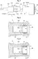
- the plug connector 120 includes: a retaining pin 121 that includes a protrusion 121a and engages with the retaining reception portion 88, which is a retaining mechanism on the receptacle connector 10 side; a gripping portion 124 by which the user grips the plug connector 120; and positioning portions 123 that engage with the positioning grooves 8b provided on the inner circumferential surface 8a of the connector case 8 to determine the position of inserting the plug connector 120 into the receptacle connector 10.
- the retaining pin 121 is a retaining mechanism on the plug connector 120 side for preventing unintended falling out in the state in which the plug connector 120 is connected to the receptacle connector 10 and for ensuring maintenance of the state in which connection is complete.
- socket-side seal member 5 is arranged at the position at which the first shell 3 and the connection tube portion 122 overlap.
- the socket-side seal member 5 is a circular column-shaped elastic member that extends in the extension direction L.
- a rubber member is used as the elastic member.
- a rubber material is used as the rubber member.
- silicone rubber or a silicone sponge is preferable as the rubber material.
- a rubber impregnated with an oil such as silicone oil is more preferably used as the rubber material.
- silicone rubber impregnated with silicone oil is used as the socket-side seal member 5.
- the socket-side seal member 5 is fixed by being fit into a waterproofing recessed portion 35 of the first shell 3.
- a waterproofing recessed portion 35 is relatively formed as a groove portion by a surface 35b on the connector side of the polyhedron portion 36 and a waterproofing protrusion 35a that is located on the connector side relative to the surface 35b and protrudes from the outer circumferential surface 3b of the first shell 3 to the outer side R2.
- waterproofing recessed portion 35 is provided on the outer circumferential surface 3b of the body portion 38 as a groove portion.
- the plug connector side L1 of the socket-side seal member 5 is locked by the waterproofing protrusion 35a and the electronic substrate side L2 of the socket-side seal member 5 is locked by the surface 35b of the polyhedron portion 36.
- the inner circumferential portion 5a which is the inner side R1 of the socket-side seal member 5 seals the gap between the first shell 3 and the socket-side seal member 5 by being pressed into contact with the outer circumferential surface 3b of the first shell 3.
- the outer circumferential portion 5b which is the outer side R2 of the socket-side seal member 5 seals the gap between the connection tube portion 122 and the socket-side seal member 5 due to being pressed into contact with the surface on the inner-side R1 of the connection tube portion 122 (see FIG. 9 ).
- the socket-side seal member 5 exhibits a waterproofing effect from the outer side of the connection tube portion 122 to the inner side of the first shell (hereinafter referred to as the "waterproofing effect of the socket-side seal member 5") due to the gap between the first shell 3 and the connection tube portion 122 of the plug module being sealed by the socket-side seal member 5.
- the first shell 3 includes the socket-side seal member 5 that seals the gap between the first shell 3 and the connection tube portion 122, if a connection tube portion 122 in which the end portion on the electronic substrate side of the connection tube portion 122 is located on the connector side relative to the waterproofing protrusion 35a in the state in which connection is complete, it is possible to disable the waterproofing function of the socket-side seal member 5.
- the waterproofing function is enabled in the case of using the plug connector 120 having a length in the extension direction L of a degree such that the connection tube portion 122 overlaps with the socket-side seal member 5 in the state in which connection is complete (see FIG. 9 ), and the waterproofing function can be disabled in the case of using the plug connector 120 having a length in the extension direction L of a degree such that the connection tube portion 122 does not overlap with the socket-side seal member 5 in the state in which connection is complete (e.g., a length according to which the end portion on the electronic substrate side of the connection tube portion 122 is located on the connector side with respect to the waterproofing protrusion 35a in the state in which connection is complete) (see FIG. 8 ).
- different plug connectors 120 can be used in the case of exhibiting the waterproofing function (the case of FIG. 9 ) and in the case of not exhibiting the waterproofing function (the case of FIG. 8 ).
- the receptacle connector 10 (connector 20) transmits the signals transmitted by the cable 130 to the camera module 110 and receives the signals transmitted by the cable 130 from the camera module 110. Furthermore, in order for the power for driving that is supplied from the cable 130 to be supplied to the camera module 110, the receptacle connector 10 is used while connected to the camera module 110.
- the camera module 110 can be used in a mode in which an electronic substrate (not shown; a printed circuit board or a flexible printed circuit board can be given as an example of the electronic substrate) is mounted on the spacer 9.
- an electronic substrate not shown; a printed circuit board or a flexible printed circuit board can be given as an example of the electronic substrate
- the camera module 110 is locked (being fixed is an example of being locked) to the leading end protrusions 33.
- the receptacle connector 10 includes the spacer 9, which includes a flat surface on the electronic substrate side L2
- the receptacle connector 10 can easily mount the substrate of the camera module 110 and thus has excellent mountability.
- the signal terminals 1 are electrically connected to the circuit wiring on the substrate through a method such as soldering.
- the connector case 8 is located on the plug connector side L1 relative to the camera module 110, and therefore is referred to as a "rear case” in some cases.
- the camera module 110 is preferably contained in the main body case 89.
- the main body case 89 is sometimes referred to as a "front case” in contrast to the connector case 8, which is referred to as the "rear case”.
- the containing space inside of which the terminal module 30, the second shell 7, the camera module 110, and the like are contained is formed due to the connector case 8 and the main body case 89 coming into contact with each other.
- the camera module 110 is an example of an electronic substrate, and includes at least an image sensor 101, an electronic circuit 102 that performs control for driving the image sensor 101 and processes image signals output from the image sensor 101, and an optical system 104 that includes a lens 103 that focuses light on the image sensor 101.
- the electronic circuit 102 is configured as an electronic substrate obtained by mounting electronic components on one or multiple substrates (e.g., printed circuit boards). In the case of using multiple electronic substrates, flexible circuit boards may be used to electrically connect the electronic substrates.
- the receptacle connector (not shown) for connecting the cable 130 via the plug connector 120 is also mounted on the electronic substrate on which the electronic circuit 102 is formed.
- the plug connector 120 is connected to the receptacle connector 10 and is connected to the cable 130 as well, whereby the camera module 110 including the electronic circuit 102 and the cable 130 are electrically connected.
- the camera unit 100 (vehicle-mounted camera) includes a camera module 110 having the image sensor 101, the electronic circuit 102 for performing driving control on the image sensor 101 and processing image signals output from the image sensor 101, and an optical system 104 that includes a lens 103 for collecting light in the image sensor 101.
- the second shell 7 functions to protect the members (at least a portion of the electronic circuit 102) that are included in the camera module 110 and are located on the electronic substrate side in the extension direction L relative to the second shell 7, by shielding them from electrical noise in the outer space E1.
- the electronic substrate is not limited to the camera module 110.
- the electronic substrate is a vehicle-mounted collision prevention sensor in some cases.
- collision prevention sensors include ultrasound sensors and terahertz wave sensors.
Landscapes
- Engineering & Computer Science (AREA)
- Multimedia (AREA)
- Signal Processing (AREA)
- Details Of Connecting Devices For Male And Female Coupling (AREA)
- Connector Housings Or Holding Contact Members (AREA)
Applications Claiming Priority (1)
| Application Number | Priority Date | Filing Date | Title |
|---|---|---|---|
| JP2016254316A JP6749232B2 (ja) | 2016-12-27 | 2016-12-27 | レセプタクルコネクタおよびカメラユニット |
Publications (2)
| Publication Number | Publication Date |
|---|---|
| EP3343705A1 true EP3343705A1 (fr) | 2018-07-04 |
| EP3343705B1 EP3343705B1 (fr) | 2019-10-16 |
Family
ID=60673597
Family Applications (1)
| Application Number | Title | Priority Date | Filing Date |
|---|---|---|---|
| EP17207419.7A Active EP3343705B1 (fr) | 2016-12-27 | 2017-12-14 | Connecteur de réceptacle et unité de caméra |
Country Status (4)
| Country | Link |
|---|---|
| US (1) | US10074924B2 (fr) |
| EP (1) | EP3343705B1 (fr) |
| JP (1) | JP6749232B2 (fr) |
| CN (1) | CN108242645B (fr) |
Cited By (2)
| Publication number | Priority date | Publication date | Assignee | Title |
|---|---|---|---|---|
| EP3343706A3 (fr) * | 2016-12-27 | 2018-10-31 | Hosiden Corporation | Connecteur de réceptacle et connecteur |
| CN113497392A (zh) * | 2020-04-07 | 2021-10-12 | 星电株式会社 | 连接器模块 |
Families Citing this family (19)
| Publication number | Priority date | Publication date | Assignee | Title |
|---|---|---|---|---|
| CN108695641A (zh) * | 2017-04-03 | 2018-10-23 | 泰科电子日本合同会社 | 密封构件及电连接器 |
| WO2019181825A1 (fr) * | 2018-03-22 | 2019-09-26 | 京セラ株式会社 | Module de caméra |
| JP2019220311A (ja) * | 2018-06-19 | 2019-12-26 | 矢崎総業株式会社 | コネクタ接続構造及び装置複合体 |
| CN108965664A (zh) * | 2018-07-09 | 2018-12-07 | 中国科学院长春光学精密机械与物理研究所 | 一种光电探测成像装置 |
| CN110858672B (zh) * | 2018-08-23 | 2023-02-21 | 本田技研工业株式会社 | 电池模块 |
| CN111596416B (zh) * | 2019-02-20 | 2022-04-26 | 利佳科技股份有限公司 | 连接器系统及其防尘件 |
| TWI702761B (zh) * | 2019-05-24 | 2020-08-21 | 香港商安費諾(東亞)有限公司 | 具有活動解鎖結構之插頭連接器及其組件 |
| CN111029839B (zh) * | 2019-12-25 | 2021-12-31 | 奇瑞新能源汽车股份有限公司 | 高压大电流屏蔽接线器 |
| DE102020204913A1 (de) * | 2020-04-17 | 2021-10-21 | Te Connectivity Germany Gmbh | Miniaturisierter Stecker |
| JP7411505B2 (ja) * | 2020-06-03 | 2024-01-11 | ホシデン株式会社 | シールド部材、シールドユニット、及びコネクタモジュール |
| WO2022005745A1 (fr) * | 2020-07-01 | 2022-01-06 | Commscope Technologies Llc | Câbles électriques, connecteurs et assemblages |
| JP7128237B2 (ja) * | 2020-07-29 | 2022-08-30 | 矢崎総業株式会社 | 防水コネクタ |
| JP7460959B2 (ja) * | 2020-09-14 | 2024-04-03 | 株式会社オートネットワーク技術研究所 | シールドコネクタ |
| US11336051B1 (en) * | 2020-11-03 | 2022-05-17 | TE Connectivity Services Gmbh | Header seal for header connector of power connector system |
| CN215418828U (zh) * | 2021-01-06 | 2022-01-04 | 东莞富强电子有限公司 | 防水插座连接器 |
| TWI835107B (zh) * | 2022-04-01 | 2024-03-11 | 佳必琪國際股份有限公司 | 插座連接器的防水結構 |
| CN115134530B (zh) * | 2022-07-18 | 2025-06-20 | 维沃移动通信有限公司 | 摄像头模组及电子设备 |
| TWI882728B (zh) * | 2024-03-15 | 2025-05-01 | 台達電子工業股份有限公司 | 安全連接結構及安全連接器 |
| JP7703088B1 (ja) | 2024-07-29 | 2025-07-04 | ホシデン株式会社 | コネクタ |
Citations (5)
| Publication number | Priority date | Publication date | Assignee | Title |
|---|---|---|---|---|
| US4990104A (en) * | 1990-05-31 | 1991-02-05 | Amp Incorporated | Snap-in retention system for coaxial contact |
| US5007862A (en) * | 1990-06-15 | 1991-04-16 | Amp Incorporated | Shielded connector having a multiply orientable housing |
| JP2000340291A (ja) * | 1999-05-27 | 2000-12-08 | Sumitomo Wiring Syst Ltd | シールドコネクタ |
| EP2833489A2 (fr) * | 2013-07-29 | 2015-02-04 | Japan Aviation Electronics Industry, Limited | Module de dispositif électronique |
| JP2016201193A (ja) | 2015-04-08 | 2016-12-01 | Smk株式会社 | コネクタ |
Family Cites Families (27)
| Publication number | Priority date | Publication date | Assignee | Title |
|---|---|---|---|---|
| US7965336B2 (en) * | 2002-11-14 | 2011-06-21 | Donnelly Corporation | Imaging system for vehicle |
| DE102004039580A1 (de) * | 2004-08-12 | 2006-02-23 | Murr-Elektronik Gmbh | Steckverbinder |
| US7967371B2 (en) * | 2007-03-20 | 2011-06-28 | Caterpillar Inc. | Machine having camera and mounting strategy therefor |
| JP4903630B2 (ja) * | 2007-05-21 | 2012-03-28 | 日本圧着端子製造株式会社 | コネクタ及び電気的接続装置 |
| JP5065992B2 (ja) * | 2008-05-22 | 2012-11-07 | 矢崎総業株式会社 | 電子機器モジュール |
| JP5467850B2 (ja) * | 2009-12-03 | 2014-04-09 | 矢崎総業株式会社 | L字型コネクタ |
| US9039424B2 (en) * | 2011-10-19 | 2015-05-26 | Winchester Electronics Corporation | Closed entry din jack and connector with PCB board lock |
| US8861951B2 (en) * | 2011-12-05 | 2014-10-14 | Flextronics Ap, Llc | Two part camera module |
| EP2907200B1 (fr) * | 2012-10-15 | 2017-07-26 | Delphi International Operations Luxembourg S.à r.l. | Connecteur électrique |
| US8740629B1 (en) * | 2012-11-29 | 2014-06-03 | Tyco Electronics Corporation | Header assembly |
| CN103078211B (zh) * | 2013-02-17 | 2014-12-10 | 安费诺-泰姆斯(常州)通讯设备有限公司 | 直角式电连接器 |
| JP6024991B2 (ja) * | 2013-06-17 | 2016-11-16 | 住友電装株式会社 | コネクタおよびハウジング |
| CN203386995U (zh) * | 2013-08-01 | 2014-01-08 | 苏州智绿环保科技有限公司 | 带高压互锁回路的大电流、高屏蔽性连接器 |
| US10298823B2 (en) * | 2014-02-03 | 2019-05-21 | Magna Electronics Inc. | Vehicle camera housing with tolerance compensating connector |
| JP6182093B2 (ja) * | 2014-03-10 | 2017-08-16 | ホシデン株式会社 | コネクタ及びこれを備えた電子機器 |
| JP6278782B2 (ja) * | 2014-03-28 | 2018-02-14 | 矢崎総業株式会社 | 同軸コネクタ及びそれを備えたカメラモジュール |
| CN203800255U (zh) * | 2014-04-18 | 2014-08-27 | 深圳市通茂电子有限公司 | 一种汽车高压连接器 |
| JP2016024863A (ja) * | 2014-07-16 | 2016-02-08 | 矢崎総業株式会社 | コネクタ |
| CN104779488B (zh) * | 2015-04-17 | 2017-06-06 | 四川永贵科技有限公司 | 弯式屏蔽mcu总线插头 |
| US20160311375A1 (en) * | 2015-04-21 | 2016-10-27 | Magna Electronics Inc. | Vehicle vision system with exchangeable cameras |
| CN205051094U (zh) * | 2015-10-15 | 2016-02-24 | 沈阳兴华华亿轨道交通电器有限公司 | 一种大电流弯式屏蔽电连接器 |
| CN205231371U (zh) * | 2015-12-18 | 2016-05-11 | 德尔福中央电气(上海)有限公司 | 一种电缆装配用屏蔽连接结构 |
| CN205248536U (zh) * | 2015-12-28 | 2016-05-18 | 四川永贵科技有限公司 | 直式高压屏蔽插头 |
| CN205429317U (zh) * | 2016-03-18 | 2016-08-03 | 泰科电子(上海)有限公司 | 连接器及连接器组件 |
| CN205657217U (zh) * | 2016-06-02 | 2016-10-19 | 莫西元 | 高压电连接器 |
| JP6704806B2 (ja) * | 2016-07-01 | 2020-06-03 | ホシデン株式会社 | コネクタモジュール及びそれを用いた車載カメラ |
| JP6797654B2 (ja) * | 2016-12-08 | 2020-12-09 | イリソ電子工業株式会社 | 電子部品及び撮像装置 |
-
2016
- 2016-12-27 JP JP2016254316A patent/JP6749232B2/ja active Active
-
2017
- 2017-12-14 EP EP17207419.7A patent/EP3343705B1/fr active Active
- 2017-12-21 US US15/850,196 patent/US10074924B2/en active Active
- 2017-12-22 CN CN201711405928.8A patent/CN108242645B/zh active Active
Patent Citations (5)
| Publication number | Priority date | Publication date | Assignee | Title |
|---|---|---|---|---|
| US4990104A (en) * | 1990-05-31 | 1991-02-05 | Amp Incorporated | Snap-in retention system for coaxial contact |
| US5007862A (en) * | 1990-06-15 | 1991-04-16 | Amp Incorporated | Shielded connector having a multiply orientable housing |
| JP2000340291A (ja) * | 1999-05-27 | 2000-12-08 | Sumitomo Wiring Syst Ltd | シールドコネクタ |
| EP2833489A2 (fr) * | 2013-07-29 | 2015-02-04 | Japan Aviation Electronics Industry, Limited | Module de dispositif électronique |
| JP2016201193A (ja) | 2015-04-08 | 2016-12-01 | Smk株式会社 | コネクタ |
Cited By (4)
| Publication number | Priority date | Publication date | Assignee | Title |
|---|---|---|---|---|
| EP3343706A3 (fr) * | 2016-12-27 | 2018-10-31 | Hosiden Corporation | Connecteur de réceptacle et connecteur |
| CN113497392A (zh) * | 2020-04-07 | 2021-10-12 | 星电株式会社 | 连接器模块 |
| EP3893333A1 (fr) * | 2020-04-07 | 2021-10-13 | Hosiden Corporation | Module connecteur |
| US11515673B2 (en) | 2020-04-07 | 2022-11-29 | Hosiden Corporation | Electrical connector module with shielding members engaging upon connection to a mating connector |
Also Published As
| Publication number | Publication date |
|---|---|
| US10074924B2 (en) | 2018-09-11 |
| US20180183169A1 (en) | 2018-06-28 |
| JP2018107036A (ja) | 2018-07-05 |
| CN108242645B (zh) | 2020-12-08 |
| CN108242645A (zh) | 2018-07-03 |
| EP3343705B1 (fr) | 2019-10-16 |
| JP6749232B2 (ja) | 2020-09-02 |
Similar Documents
| Publication | Publication Date | Title |
|---|---|---|
| EP3343705B1 (fr) | Connecteur de réceptacle et unité de caméra | |
| EP3343706B1 (fr) | Connecteur de réceptacle et connecteur | |
| EP3462550B1 (fr) | Module de connecteur et caméra embarquée l'utilisant | |
| CN107565246B (zh) | 连接器模块及使用该连接器模块的车载照相机 | |
| US11515673B2 (en) | Electrical connector module with shielding members engaging upon connection to a mating connector | |
| EP3430797B1 (fr) | Ensemble caméra avec circuit d'imageur protégé | |
| US10224666B2 (en) | Packing and shield connector | |
| US11569611B2 (en) | Connector assembly with an intermediate insulating member and a potting material that fills a portion in an outer conductor more on the front side than on the front surface of the intermediate insulating member | |
| EP4089845A1 (fr) | Connecteur coaxial | |
| CN103460517B (zh) | 屏蔽连接器 | |
| JP2019067740A (ja) | コネクタモジュール及びそれを用いた車載カメラ | |
| US10403995B2 (en) | Electrical connector, electronic component, and assembly method | |
| KR102510778B1 (ko) | 방수용 커넥터 | |
| WO2012091053A1 (fr) | Structure de blindage de faisceau de câbles | |
| EP2907199B1 (fr) | Système de connexion électrique | |
| JP2017208286A (ja) | ケーブル用コネクタ | |
| CN212460629U (zh) | 行车记录仪 | |
| KR100800788B1 (ko) | 실드쉘 접속수단 및 이를 구비한 실드커넥터 | |
| JP2017098199A (ja) | コネクタ | |
| JP2018098042A (ja) | 同軸コネクタ |
Legal Events
| Date | Code | Title | Description |
|---|---|---|---|
| PUAI | Public reference made under article 153(3) epc to a published international application that has entered the european phase |
Free format text: ORIGINAL CODE: 0009012 |
|
| STAA | Information on the status of an ep patent application or granted ep patent |
Free format text: STATUS: THE APPLICATION HAS BEEN PUBLISHED |
|
| AK | Designated contracting states |
Kind code of ref document: A1 Designated state(s): AL AT BE BG CH CY CZ DE DK EE ES FI FR GB GR HR HU IE IS IT LI LT LU LV MC MK MT NL NO PL PT RO RS SE SI SK SM TR |
|
| AX | Request for extension of the european patent |
Extension state: BA ME |
|
| STAA | Information on the status of an ep patent application or granted ep patent |
Free format text: STATUS: REQUEST FOR EXAMINATION WAS MADE |
|
| 17P | Request for examination filed |
Effective date: 20181211 |
|
| RBV | Designated contracting states (corrected) |
Designated state(s): AL AT BE BG CH CY CZ DE DK EE ES FI FR GB GR HR HU IE IS IT LI LT LU LV MC MK MT NL NO PL PT RO RS SE SI SK SM TR |
|
| REG | Reference to a national code |
Ref country code: DE Ref legal event code: R079 Ref document number: 602017007865 Country of ref document: DE Free format text: PREVIOUS MAIN CLASS: H01R0013436000 Ipc: H04N0005225000 |
|
| GRAP | Despatch of communication of intention to grant a patent |
Free format text: ORIGINAL CODE: EPIDOSNIGR1 |
|
| STAA | Information on the status of an ep patent application or granted ep patent |
Free format text: STATUS: GRANT OF PATENT IS INTENDED |
|
| RIC1 | Information provided on ipc code assigned before grant |
Ipc: H01R 13/506 20060101ALI20190319BHEP Ipc: H01R 13/41 20060101ALI20190319BHEP Ipc: H01R 12/71 20110101ALI20190319BHEP Ipc: H04N 5/225 20060101AFI20190319BHEP Ipc: H01R 13/04 20060101ALI20190319BHEP Ipc: H01R 13/405 20060101ALI20190319BHEP Ipc: H01R 13/6594 20110101ALI20190319BHEP Ipc: H01R 13/52 20060101ALI20190319BHEP Ipc: H01R 13/436 20060101ALI20190319BHEP |
|
| INTG | Intention to grant announced |
Effective date: 20190424 |
|
| GRAJ | Information related to disapproval of communication of intention to grant by the applicant or resumption of examination proceedings by the epo deleted |
Free format text: ORIGINAL CODE: EPIDOSDIGR1 |
|
| STAA | Information on the status of an ep patent application or granted ep patent |
Free format text: STATUS: REQUEST FOR EXAMINATION WAS MADE |
|
| GRAS | Grant fee paid |
Free format text: ORIGINAL CODE: EPIDOSNIGR3 |
|
| STAA | Information on the status of an ep patent application or granted ep patent |
Free format text: STATUS: GRANT OF PATENT IS INTENDED |
|
| GRAP | Despatch of communication of intention to grant a patent |
Free format text: ORIGINAL CODE: EPIDOSNIGR1 |
|
| RAP1 | Party data changed (applicant data changed or rights of an application transferred) |
Owner name: HOSIDEN CORPORATION |
|
| INTC | Intention to grant announced (deleted) | ||
| INTG | Intention to grant announced |
Effective date: 20190716 |
|
| GRAA | (expected) grant |
Free format text: ORIGINAL CODE: 0009210 |
|
| STAA | Information on the status of an ep patent application or granted ep patent |
Free format text: STATUS: THE PATENT HAS BEEN GRANTED |
|
| AK | Designated contracting states |
Kind code of ref document: B1 Designated state(s): AL AT BE BG CH CY CZ DE DK EE ES FI FR GB GR HR HU IE IS IT LI LT LU LV MC MK MT NL NO PL PT RO RS SE SI SK SM TR |
|
| REG | Reference to a national code |
Ref country code: GB Ref legal event code: FG4D |
|
| REG | Reference to a national code |
Ref country code: CH Ref legal event code: EP |
|
| REG | Reference to a national code |
Ref country code: DE Ref legal event code: R096 Ref document number: 602017007865 Country of ref document: DE |
|
| REG | Reference to a national code |
Ref country code: IE Ref legal event code: FG4D |
|
| REG | Reference to a national code |
Ref country code: AT Ref legal event code: REF Ref document number: 1192455 Country of ref document: AT Kind code of ref document: T Effective date: 20191115 |
|
| REG | Reference to a national code |
Ref country code: NL Ref legal event code: MP Effective date: 20191016 |
|
| REG | Reference to a national code |
Ref country code: LT Ref legal event code: MG4D |
|
| REG | Reference to a national code |
Ref country code: AT Ref legal event code: MK05 Ref document number: 1192455 Country of ref document: AT Kind code of ref document: T Effective date: 20191016 |
|
| PG25 | Lapsed in a contracting state [announced via postgrant information from national office to epo] |
Ref country code: SE Free format text: LAPSE BECAUSE OF FAILURE TO SUBMIT A TRANSLATION OF THE DESCRIPTION OR TO PAY THE FEE WITHIN THE PRESCRIBED TIME-LIMIT Effective date: 20191016 Ref country code: AT Free format text: LAPSE BECAUSE OF FAILURE TO SUBMIT A TRANSLATION OF THE DESCRIPTION OR TO PAY THE FEE WITHIN THE PRESCRIBED TIME-LIMIT Effective date: 20191016 Ref country code: LV Free format text: LAPSE BECAUSE OF FAILURE TO SUBMIT A TRANSLATION OF THE DESCRIPTION OR TO PAY THE FEE WITHIN THE PRESCRIBED TIME-LIMIT Effective date: 20191016 Ref country code: NL Free format text: LAPSE BECAUSE OF FAILURE TO SUBMIT A TRANSLATION OF THE DESCRIPTION OR TO PAY THE FEE WITHIN THE PRESCRIBED TIME-LIMIT Effective date: 20191016 Ref country code: LT Free format text: LAPSE BECAUSE OF FAILURE TO SUBMIT A TRANSLATION OF THE DESCRIPTION OR TO PAY THE FEE WITHIN THE PRESCRIBED TIME-LIMIT Effective date: 20191016 Ref country code: GR Free format text: LAPSE BECAUSE OF FAILURE TO SUBMIT A TRANSLATION OF THE DESCRIPTION OR TO PAY THE FEE WITHIN THE PRESCRIBED TIME-LIMIT Effective date: 20200117 Ref country code: NO Free format text: LAPSE BECAUSE OF FAILURE TO SUBMIT A TRANSLATION OF THE DESCRIPTION OR TO PAY THE FEE WITHIN THE PRESCRIBED TIME-LIMIT Effective date: 20200116 Ref country code: PL Free format text: LAPSE BECAUSE OF FAILURE TO SUBMIT A TRANSLATION OF THE DESCRIPTION OR TO PAY THE FEE WITHIN THE PRESCRIBED TIME-LIMIT Effective date: 20191016 Ref country code: FI Free format text: LAPSE BECAUSE OF FAILURE TO SUBMIT A TRANSLATION OF THE DESCRIPTION OR TO PAY THE FEE WITHIN THE PRESCRIBED TIME-LIMIT Effective date: 20191016 Ref country code: BG Free format text: LAPSE BECAUSE OF FAILURE TO SUBMIT A TRANSLATION OF THE DESCRIPTION OR TO PAY THE FEE WITHIN THE PRESCRIBED TIME-LIMIT Effective date: 20200116 Ref country code: PT Free format text: LAPSE BECAUSE OF FAILURE TO SUBMIT A TRANSLATION OF THE DESCRIPTION OR TO PAY THE FEE WITHIN THE PRESCRIBED TIME-LIMIT Effective date: 20200217 |
|
| PG25 | Lapsed in a contracting state [announced via postgrant information from national office to epo] |
Ref country code: HR Free format text: LAPSE BECAUSE OF FAILURE TO SUBMIT A TRANSLATION OF THE DESCRIPTION OR TO PAY THE FEE WITHIN THE PRESCRIBED TIME-LIMIT Effective date: 20191016 Ref country code: RS Free format text: LAPSE BECAUSE OF FAILURE TO SUBMIT A TRANSLATION OF THE DESCRIPTION OR TO PAY THE FEE WITHIN THE PRESCRIBED TIME-LIMIT Effective date: 20191016 Ref country code: IS Free format text: LAPSE BECAUSE OF FAILURE TO SUBMIT A TRANSLATION OF THE DESCRIPTION OR TO PAY THE FEE WITHIN THE PRESCRIBED TIME-LIMIT Effective date: 20200224 |
|
| PG25 | Lapsed in a contracting state [announced via postgrant information from national office to epo] |
Ref country code: AL Free format text: LAPSE BECAUSE OF FAILURE TO SUBMIT A TRANSLATION OF THE DESCRIPTION OR TO PAY THE FEE WITHIN THE PRESCRIBED TIME-LIMIT Effective date: 20191016 |
|
| REG | Reference to a national code |
Ref country code: DE Ref legal event code: R097 Ref document number: 602017007865 Country of ref document: DE |
|
| PG2D | Information on lapse in contracting state deleted |
Ref country code: IS |
|
| PG25 | Lapsed in a contracting state [announced via postgrant information from national office to epo] |
Ref country code: CZ Free format text: LAPSE BECAUSE OF FAILURE TO SUBMIT A TRANSLATION OF THE DESCRIPTION OR TO PAY THE FEE WITHIN THE PRESCRIBED TIME-LIMIT Effective date: 20191016 Ref country code: RO Free format text: LAPSE BECAUSE OF FAILURE TO SUBMIT A TRANSLATION OF THE DESCRIPTION OR TO PAY THE FEE WITHIN THE PRESCRIBED TIME-LIMIT Effective date: 20191016 Ref country code: EE Free format text: LAPSE BECAUSE OF FAILURE TO SUBMIT A TRANSLATION OF THE DESCRIPTION OR TO PAY THE FEE WITHIN THE PRESCRIBED TIME-LIMIT Effective date: 20191016 Ref country code: DK Free format text: LAPSE BECAUSE OF FAILURE TO SUBMIT A TRANSLATION OF THE DESCRIPTION OR TO PAY THE FEE WITHIN THE PRESCRIBED TIME-LIMIT Effective date: 20191016 Ref country code: ES Free format text: LAPSE BECAUSE OF FAILURE TO SUBMIT A TRANSLATION OF THE DESCRIPTION OR TO PAY THE FEE WITHIN THE PRESCRIBED TIME-LIMIT Effective date: 20191016 Ref country code: IS Free format text: LAPSE BECAUSE OF FAILURE TO SUBMIT A TRANSLATION OF THE DESCRIPTION OR TO PAY THE FEE WITHIN THE PRESCRIBED TIME-LIMIT Effective date: 20200216 |
|
| PLBE | No opposition filed within time limit |
Free format text: ORIGINAL CODE: 0009261 |
|
| STAA | Information on the status of an ep patent application or granted ep patent |
Free format text: STATUS: NO OPPOSITION FILED WITHIN TIME LIMIT |
|
| REG | Reference to a national code |
Ref country code: BE Ref legal event code: MM Effective date: 20191231 |
|
| PG25 | Lapsed in a contracting state [announced via postgrant information from national office to epo] |
Ref country code: SK Free format text: LAPSE BECAUSE OF FAILURE TO SUBMIT A TRANSLATION OF THE DESCRIPTION OR TO PAY THE FEE WITHIN THE PRESCRIBED TIME-LIMIT Effective date: 20191016 Ref country code: IT Free format text: LAPSE BECAUSE OF FAILURE TO SUBMIT A TRANSLATION OF THE DESCRIPTION OR TO PAY THE FEE WITHIN THE PRESCRIBED TIME-LIMIT Effective date: 20191016 Ref country code: SM Free format text: LAPSE BECAUSE OF FAILURE TO SUBMIT A TRANSLATION OF THE DESCRIPTION OR TO PAY THE FEE WITHIN THE PRESCRIBED TIME-LIMIT Effective date: 20191016 Ref country code: MC Free format text: LAPSE BECAUSE OF FAILURE TO SUBMIT A TRANSLATION OF THE DESCRIPTION OR TO PAY THE FEE WITHIN THE PRESCRIBED TIME-LIMIT Effective date: 20191016 |
|
| 26N | No opposition filed |
Effective date: 20200717 |
|
| PG25 | Lapsed in a contracting state [announced via postgrant information from national office to epo] |
Ref country code: LU Free format text: LAPSE BECAUSE OF NON-PAYMENT OF DUE FEES Effective date: 20191214 Ref country code: IE Free format text: LAPSE BECAUSE OF NON-PAYMENT OF DUE FEES Effective date: 20191214 |
|
| PG25 | Lapsed in a contracting state [announced via postgrant information from national office to epo] |
Ref country code: BE Free format text: LAPSE BECAUSE OF NON-PAYMENT OF DUE FEES Effective date: 20191231 Ref country code: SI Free format text: LAPSE BECAUSE OF FAILURE TO SUBMIT A TRANSLATION OF THE DESCRIPTION OR TO PAY THE FEE WITHIN THE PRESCRIBED TIME-LIMIT Effective date: 20191016 |
|
| PG25 | Lapsed in a contracting state [announced via postgrant information from national office to epo] |
Ref country code: CY Free format text: LAPSE BECAUSE OF FAILURE TO SUBMIT A TRANSLATION OF THE DESCRIPTION OR TO PAY THE FEE WITHIN THE PRESCRIBED TIME-LIMIT Effective date: 20191016 |
|
| PG25 | Lapsed in a contracting state [announced via postgrant information from national office to epo] |
Ref country code: MT Free format text: LAPSE BECAUSE OF FAILURE TO SUBMIT A TRANSLATION OF THE DESCRIPTION OR TO PAY THE FEE WITHIN THE PRESCRIBED TIME-LIMIT Effective date: 20191016 Ref country code: HU Free format text: LAPSE BECAUSE OF FAILURE TO SUBMIT A TRANSLATION OF THE DESCRIPTION OR TO PAY THE FEE WITHIN THE PRESCRIBED TIME-LIMIT; INVALID AB INITIO Effective date: 20171214 |
|
| REG | Reference to a national code |
Ref country code: CH Ref legal event code: PL |
|
| PG25 | Lapsed in a contracting state [announced via postgrant information from national office to epo] |
Ref country code: CH Free format text: LAPSE BECAUSE OF NON-PAYMENT OF DUE FEES Effective date: 20201231 Ref country code: LI Free format text: LAPSE BECAUSE OF NON-PAYMENT OF DUE FEES Effective date: 20201231 |
|
| PG25 | Lapsed in a contracting state [announced via postgrant information from national office to epo] |
Ref country code: TR Free format text: LAPSE BECAUSE OF FAILURE TO SUBMIT A TRANSLATION OF THE DESCRIPTION OR TO PAY THE FEE WITHIN THE PRESCRIBED TIME-LIMIT Effective date: 20191016 |
|
| PG25 | Lapsed in a contracting state [announced via postgrant information from national office to epo] |
Ref country code: MK Free format text: LAPSE BECAUSE OF FAILURE TO SUBMIT A TRANSLATION OF THE DESCRIPTION OR TO PAY THE FEE WITHIN THE PRESCRIBED TIME-LIMIT Effective date: 20191016 |
|
| REG | Reference to a national code |
Ref country code: DE Ref legal event code: R079 Ref document number: 602017007865 Country of ref document: DE Free format text: PREVIOUS MAIN CLASS: H04N0005225000 Ipc: H04N0023000000 |
|
| PGFP | Annual fee paid to national office [announced via postgrant information from national office to epo] |
Ref country code: GB Payment date: 20251218 Year of fee payment: 9 |
|
| PGFP | Annual fee paid to national office [announced via postgrant information from national office to epo] |
Ref country code: FR Payment date: 20251218 Year of fee payment: 9 |
|
| PGFP | Annual fee paid to national office [announced via postgrant information from national office to epo] |
Ref country code: DE Payment date: 20251217 Year of fee payment: 9 |