EP3343731B1 - Système d'alimentation électrique sans contact et dispositif de réception d'énergie - Google Patents
Système d'alimentation électrique sans contact et dispositif de réception d'énergie Download PDFInfo
- Publication number
- EP3343731B1 EP3343731B1 EP16841335.9A EP16841335A EP3343731B1 EP 3343731 B1 EP3343731 B1 EP 3343731B1 EP 16841335 A EP16841335 A EP 16841335A EP 3343731 B1 EP3343731 B1 EP 3343731B1
- Authority
- EP
- European Patent Office
- Prior art keywords
- power
- receiving
- formula
- impedance
- coupling coefficient
- Prior art date
- Legal status (The legal status is an assumption and is not a legal conclusion. Google has not performed a legal analysis and makes no representation as to the accuracy of the status listed.)
- Active
Links
Images








Classifications
-
- H—ELECTRICITY
- H02—GENERATION; CONVERSION OR DISTRIBUTION OF ELECTRIC POWER
- H02J—ELECTRIC POWER NETWORKS; CIRCUIT ARRANGEMENTS OR SYSTEMS FOR SUPPLYING OR DISTRIBUTING ELECTRIC POWER; SYSTEMS FOR STORING ELECTRIC ENERGY
- H02J50/00—Circuit arrangements or systems for wireless supply or distribution of electric power
- H02J50/10—Circuit arrangements or systems for wireless supply or distribution of electric power using inductive coupling
- H02J50/12—Circuit arrangements or systems for wireless supply or distribution of electric power using inductive coupling of the resonant type
-
- B—PERFORMING OPERATIONS; TRANSPORTING
- B60—VEHICLES IN GENERAL
- B60L—PROPULSION OF ELECTRICALLY-PROPELLED VEHICLES; SUPPLYING ELECTRIC POWER FOR AUXILIARY EQUIPMENT OF ELECTRICALLY-PROPELLED VEHICLES; ELECTRODYNAMIC BRAKE SYSTEMS FOR VEHICLES IN GENERAL; MAGNETIC SUSPENSION OR LEVITATION FOR VEHICLES; MONITORING OPERATING VARIABLES OF ELECTRICALLY-PROPELLED VEHICLES; ELECTRIC SAFETY DEVICES FOR ELECTRICALLY-PROPELLED VEHICLES
- B60L53/00—Methods of charging batteries, specially adapted for electric vehicles; Charging stations or on-board charging equipment therefor; Exchange of energy storage elements in electric vehicles
- B60L53/10—Methods of charging batteries, specially adapted for electric vehicles; Charging stations or on-board charging equipment therefor; Exchange of energy storage elements in electric vehicles characterised by the energy transfer between the charging station and the vehicle
- B60L53/12—Inductive energy transfer
- B60L53/122—Circuits or methods for driving the primary coil, e.g. supplying electric power to the coil
-
- B—PERFORMING OPERATIONS; TRANSPORTING
- B60—VEHICLES IN GENERAL
- B60L—PROPULSION OF ELECTRICALLY-PROPELLED VEHICLES; SUPPLYING ELECTRIC POWER FOR AUXILIARY EQUIPMENT OF ELECTRICALLY-PROPELLED VEHICLES; ELECTRODYNAMIC BRAKE SYSTEMS FOR VEHICLES IN GENERAL; MAGNETIC SUSPENSION OR LEVITATION FOR VEHICLES; MONITORING OPERATING VARIABLES OF ELECTRICALLY-PROPELLED VEHICLES; ELECTRIC SAFETY DEVICES FOR ELECTRICALLY-PROPELLED VEHICLES
- B60L53/00—Methods of charging batteries, specially adapted for electric vehicles; Charging stations or on-board charging equipment therefor; Exchange of energy storage elements in electric vehicles
- B60L53/10—Methods of charging batteries, specially adapted for electric vehicles; Charging stations or on-board charging equipment therefor; Exchange of energy storage elements in electric vehicles characterised by the energy transfer between the charging station and the vehicle
- B60L53/12—Inductive energy transfer
- B60L53/126—Methods for pairing a vehicle and a charging station, e.g. establishing a one-to-one relation between a wireless power transmitter and a wireless power receiver
-
- H—ELECTRICITY
- H01—ELECTRIC ELEMENTS
- H01F—MAGNETS; INDUCTANCES; TRANSFORMERS; SELECTION OF MATERIALS FOR THEIR MAGNETIC PROPERTIES
- H01F38/00—Adaptations of transformers or inductances for specific applications or functions
- H01F38/14—Inductive couplings
-
- H—ELECTRICITY
- H02—GENERATION; CONVERSION OR DISTRIBUTION OF ELECTRIC POWER
- H02J—ELECTRIC POWER NETWORKS; CIRCUIT ARRANGEMENTS OR SYSTEMS FOR SUPPLYING OR DISTRIBUTING ELECTRIC POWER; SYSTEMS FOR STORING ELECTRIC ENERGY
- H02J50/00—Circuit arrangements or systems for wireless supply or distribution of electric power
- H02J50/90—Circuit arrangements or systems for wireless supply or distribution of electric power involving detection or optimisation of position, e.g. alignment
-
- H—ELECTRICITY
- H02—GENERATION; CONVERSION OR DISTRIBUTION OF ELECTRIC POWER
- H02J—ELECTRIC POWER NETWORKS; CIRCUIT ARRANGEMENTS OR SYSTEMS FOR SUPPLYING OR DISTRIBUTING ELECTRIC POWER; SYSTEMS FOR STORING ELECTRIC ENERGY
- H02J50/00—Circuit arrangements or systems for wireless supply or distribution of electric power
- H02J50/80—Circuit arrangements or systems for wireless supply or distribution of electric power involving the exchange of data, concerning supply or distribution of electric power, between transmitting devices and receiving devices
-
- Y—GENERAL TAGGING OF NEW TECHNOLOGICAL DEVELOPMENTS; GENERAL TAGGING OF CROSS-SECTIONAL TECHNOLOGIES SPANNING OVER SEVERAL SECTIONS OF THE IPC; TECHNICAL SUBJECTS COVERED BY FORMER USPC CROSS-REFERENCE ART COLLECTIONS [XRACs] AND DIGESTS
- Y02—TECHNOLOGIES OR APPLICATIONS FOR MITIGATION OR ADAPTATION AGAINST CLIMATE CHANGE
- Y02T—CLIMATE CHANGE MITIGATION TECHNOLOGIES RELATED TO TRANSPORTATION
- Y02T10/00—Road transport of goods or passengers
- Y02T10/60—Other road transportation technologies with climate change mitigation effect
- Y02T10/70—Energy storage systems for electromobility, e.g. batteries
-
- Y—GENERAL TAGGING OF NEW TECHNOLOGICAL DEVELOPMENTS; GENERAL TAGGING OF CROSS-SECTIONAL TECHNOLOGIES SPANNING OVER SEVERAL SECTIONS OF THE IPC; TECHNICAL SUBJECTS COVERED BY FORMER USPC CROSS-REFERENCE ART COLLECTIONS [XRACs] AND DIGESTS
- Y02—TECHNOLOGIES OR APPLICATIONS FOR MITIGATION OR ADAPTATION AGAINST CLIMATE CHANGE
- Y02T—CLIMATE CHANGE MITIGATION TECHNOLOGIES RELATED TO TRANSPORTATION
- Y02T10/00—Road transport of goods or passengers
- Y02T10/60—Other road transportation technologies with climate change mitigation effect
- Y02T10/7072—Electromobility specific charging systems or methods for batteries, ultracapacitors, supercapacitors or double-layer capacitors
-
- Y—GENERAL TAGGING OF NEW TECHNOLOGICAL DEVELOPMENTS; GENERAL TAGGING OF CROSS-SECTIONAL TECHNOLOGIES SPANNING OVER SEVERAL SECTIONS OF THE IPC; TECHNICAL SUBJECTS COVERED BY FORMER USPC CROSS-REFERENCE ART COLLECTIONS [XRACs] AND DIGESTS
- Y02—TECHNOLOGIES OR APPLICATIONS FOR MITIGATION OR ADAPTATION AGAINST CLIMATE CHANGE
- Y02T—CLIMATE CHANGE MITIGATION TECHNOLOGIES RELATED TO TRANSPORTATION
- Y02T90/00—Enabling technologies or technologies with a potential or indirect contribution to GHG emissions mitigation
- Y02T90/10—Technologies relating to charging of electric vehicles
- Y02T90/12—Electric charging stations
-
- Y—GENERAL TAGGING OF NEW TECHNOLOGICAL DEVELOPMENTS; GENERAL TAGGING OF CROSS-SECTIONAL TECHNOLOGIES SPANNING OVER SEVERAL SECTIONS OF THE IPC; TECHNICAL SUBJECTS COVERED BY FORMER USPC CROSS-REFERENCE ART COLLECTIONS [XRACs] AND DIGESTS
- Y02—TECHNOLOGIES OR APPLICATIONS FOR MITIGATION OR ADAPTATION AGAINST CLIMATE CHANGE
- Y02T—CLIMATE CHANGE MITIGATION TECHNOLOGIES RELATED TO TRANSPORTATION
- Y02T90/00—Enabling technologies or technologies with a potential or indirect contribution to GHG emissions mitigation
- Y02T90/10—Technologies relating to charging of electric vehicles
- Y02T90/14—Plug-in electric vehicles
Definitions
- the present invention relates to a wireless power supply system.
- the battery charging of an electric vehicle has attracted attention as one application destination of the wireless power supply system.
- the power receiver is mounted on the vehicle in this case.
- driving accuracy stop accuracy
- the efficiency of transmission may decrease due to a change in a coupling coefficient between the coils.
- Patent Document 1 A power supply device (power transmitter) disclosed in Patent Document1 changes the frequency of AC power which is supplied from an inverter circuit (power source) to a power-transmitting coil, when the efficiency of transmission decreases due to the occurrence of positional misalignment.
- the power supply device achieves an improvement in the efficiency of charging through this frequency change.
- Patent Document 2 (prior art in the sense of Art. 54(3) EPC) discloses: a wireless power supply system including a power transmitter and a power receiver.
- the power transmitter includes a power-transmitting coil to which AC power of a frequency is input from a power source.
- the power receiver includes a power-receiving coil magnetically coupled to the power-transmitting coil at a coupling coefficient, and a first power-receiving side series element coupled in series to the power-receiving coil and having imaginary impedance jZ S2i .
- the frequency and the imaginary impedance are determined so that impedance of a power-receiving side seen from the power source is independent of the coupling coefficient when the coupling coefficient changes.
- Conference Paper 1 discloses: a practical study on variable frequency, variable load and variable distance of a planar contactless power transfer (CPT) system. This prior art is reflected by the preamble of the independent claims.
- CPT planar contactless power transfer
- impedance of the power-receiving side seen from the inverter circuit is expressed by a function of the frequency of electric power supplied to the power-transmitting coil and the coupling coefficient between the power-transmitting coil and the power-receiving coil. For this reason, by changing the frequency when the positional misalignment occurs and the coupling coefficient changes, a change in the coupling coefficient and the frequency incurs a change in impedance.
- the output AC voltage of the inverter circuit (or corresponding input DC voltage of the inverter circuit) also changes in order to supply desired electric power, due to such a change in impedance.
- the circuit element of the power transmitter is, for example, a field effect transistor (FET) as a switching element of the inverter circuit.
- FET field effect transistor
- the output voltage of the inverter circuit becomes lower, an output current from the inverter circuit is required to be increased in order to transmit desired electric power. In a case where the output current becomes larger, a Joule heat loss in an element or a wiring through which this current flows may increase, and the efficiency of charging may decrease.
- an object of the present invention is to provide a wireless power supply system and a power receiver which are capable of suppressing a fluctuation in impedance of a power-receiving side seen from a power source, when a coupling coefficient changes.
- the coefficient K I is a value larger than 0 and smaller than 1, or a value larger than 1.
- the power transmitter further includes: a power-transmission-side parallel element coupled in parallel to the power-transmitting coil and having imaginary impedance jZ P1i ; and a first power-transmission-side series element coupled in series to the power-transmitting coil at a position closer to the power-transmitting coil than the power-transmission-side parallel element and having imaginary impedance jZsii 2
- the wireless power supply system may be configured to determine: a variable range of the frequency, a fluctuation range of the coupling coefficient, and the imaginary impedances of the first power-receiving-side series element and the power-receiving-side parallel element so as to satisfy Formula (1), when the frequency is an upper limit or a lower limit of the variable range and the coupling coefficient is an upper limit or a lower limit of the fluctuation range.
- the wireless power supply system may be configured to determine the imaginary impedances of the first power-receiving-side series element and the power-receiving-side parallel element so that a phase difference between an electromotive force induced in the power-receiving coil by magnetic coupling of the power-transmitting coil to the power-receiving coil and the current of the power receiving coil is 0°.
- a load whose impedance fluctuates may be coupled to the power receiver, and the wireless power supply system may be configured to determine the imaginary impedances of the first power-receiving-side series element and the power-receiving-side parallel element so as to satisfy Formula (1) irrespective of the impedance of the load, when the frequency is the upper limit or the lower limit of the variable range and the coupling coefficient is the lower limit of the fluctuation range.
- the first power-receiving-side series element may be an inductor
- the power-receiving-side parallel element may be a capacitor
- the first power-receiving-side series element and the power-receiving-side parallel element may be capacitors.
- the power transmitter further includes: a power-transmission-side parallel element coupled in parallel to the power-transmitting coil and having imaginary impedance jZ P1i ; and a first power-transmission-side series element coupled in series to the power-transmitting coil at a position closer to the power-transmitting coil than the power-transmission-side parallel element and having imaginary impedance jZ S1i-2
- the power receiver further includes: a power-receiving-side parallel element coupled in parallel to the power-receiving coil at a position closer to the power-receiving coil than the first power-receiving-side series element and having imaginary impedance jZ P2i ; and a second power-receiving-side series element coupled in series to the power-receiving coil at a position closer to the power-receiving coil than the power-receiving-side parallel element and having imaginary impedance jZ S2i-2 , the imaginary impedances of the first power
- the wireless power supply system may be configured to determine: a variable range of the frequency, a fluctuation range of the coupling coefficient, and the imaginary impedances of the first power-receiving-side series element, the second power-receiving-side series element and the power-receiving-side parallel element so as to satisfy Formula (1), when the frequency is an upper limit or a lower limit of the variable range and the coupling coefficient is an upper limit or a lower limit of the fluctuation range.
- a load whose impedance fluctuates may be coupled to the power receiver, and the wireless power supply system may be configured to determine the imaginary impedances of the first power-receiving-side series element, the second power-receiving-side series element and the power-receiving-side parallel element so as to satisfy Formula (1) irrespective of the impedance of the load, when the frequency is the upper limit or the lower limit of the variable range and the coupling coefficient is the lower limit of the fluctuation range.
- the wireless power supply system may be configured to determine the imaginary impedances of the first power-receiving-side series element, the second power-receiving-side series element and the power-receiving-side parallel element so that a phase difference between an electromotive force induced in the power-receiving coil by magnetic coupling of the power-transmitting coil to the power-receiving coil and the current of the power receiving coil is 0°.
- the first power-receiving-side series element may be an inductor
- the second power-receiving-side series element and the power-receiving-side parallel element may be capacitors.
- the first power-receiving-side series element, the second power-receiving-side series element and the power-receiving-side parallel element may be capacitors.
- the power transmitter further includes a power-transmission-side series element coupled in series to the power-transmitting coil and having imaginary impedance jZ s1i , and the imaginary impedances of the power-transmission-side series element and the first power-receiving-side series element satisfy the following formula.
- Z S 1 i L 1 L 2 K I 2 Z S 2 i + K I 2 ⁇ 1 ⁇ L 2
- the power transmitter may further include a power-transmission-side series element coupled in series to the power-transmitting coil at a position closer to the power source than the power-transmission-side parallel element and having imaginary impedance jZ s1i , and the imaginary impedances of the power-transmission-side series element and the first power-receiving-side series element satisfy the following formula.
- Z S 1 i K I 2 L 1 L 2 Z S 2 i
- the power transmitter may further include a second power-transmission-side series element coupled in series to the power-transmitting coil at a position closer to the power source than the power-transmission-side parallel element and having imaginary impedance jZ s1i , and the imaginary impedances of the second power-transmission-side series element and the first power-receiving-side series element satisfy the following formula.
- Z S 1 i K I 2 L 1 L 2 Z S 2 i
- the first power-receiving-side series element may be a variable element.
- At least one of the first power-receiving-side series element and the power-receiving-side parallel element may be a variable element.
- At least one of the first power-receiving-side series element, the power-receiving-side parallel element and the second power-receiving-side series element may be a variable element.
- the wireless power supply system is configured to determine a fluctuation range of the coupling coefficient, and the coefficient K I satisfies 0 ⁇ K I ⁇ 1.
- the wireless power supply system (100, 200, 300, 500) is configured to determine a fluctuation range of the coupling coefficient, and when the self-inductances of the power-transmitting coil and the power-receiving coil change on the basis of change in the coupling coefficient, the self-inductances of the power-transmitting coil and the power-receiving coil take values within a changing range of the self-inductances depending on change in the coupling coefficient within the fluctuation range.
- the present invention it is possible to suppress a fluctuation in impedance of a power-receiving side seen from a power source, when a coupling coefficient changes.
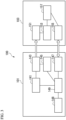
- FIG. 1 is a circuit diagram of a wireless power supply system according to a first embodiment of the present invention.
- a wireless power supply system 100 includes a power transmitter 101 and a power receiver 103.
- the power transmitter 101 includes a power-transmitting coil 113 described later, and the power receiver 103 include a power-receiving coil 121 described later.
- the power transmitter 101 transmits electric power to the power receiver 103 wirelessly through magnetic coupling between the coils.
- a method of transmitting electric power under magnetic coupling between coils is, for example, an electromagnetic induction method or a magnetic resonance method.
- Application examples of the wireless power supply system 100 include, for example, charging systems or driving systems of moving objects such as an electric vehicle (vehicle) or an underwater sailing body, home electric appliances, or medical instruments.
- the power-transmitting coil 113 and the power-receiving coil 121 are, for example, solenoid-type or circular-type coils.
- the solenoid-type is an aspect in which a conducting wire which forms a coil is helically wound in three-dimensional space.
- the circular-type coil is an aspect in which a conducting wire which forms a coil is spirally wound on a plane.
- the power transmitter 101 includes the power-transmitting coil 113 to which an AC power is input from a power source 111 that outputs AC power of a frequency f, and an element (power-transmission-side series element) 115 having imaginary impedance. That is, the power-transmitting coil 113 is configured to receive AC power of a frequency f from the power source 111.
- the description of "AC power of a frequency f" means that a frequency of an AC voltage or an alternating current output from the power source 111 is f.
- the element 115 is coupled in series to the power source 111 and the power-transmitting coil 113.
- Self-inductance of the power-transmitting coil 113 is denoted by Li, and a current I 1 (phasor current) flows through the power-transmitting coil 113.
- the absolute value of a current displayed by phasor may be an effective value, or may be a peak value.
- the power source 111 is, for example, a power supply circuit such as an inverter circuit or an AC power source such as a commercially available power source, and outputs an AC voltage Vs (phasor voltage) of a frequency f (angular frequency ⁇ ).
- the inverter circuit can be realized by methods conventionally known such as a half-bridge method or a full-bridge method.
- the absolute value of a voltage displayed by phasor may be an effective value, or may be a peak value.
- the inverter circuit When the power source 111 is constituted by an inverter circuit, the inverter circuit includes a plurality of switching elements (such as field effect transistors), and these elements are switched at a switching frequency f, whereby AC power of the frequency f is output from the power source 111. That is, a switching frequency is controlled in order to change the frequency of an inverter circuit output.
- switching elements such as field effect transistors
- DC power is input to the inverter circuit, but this DC power is, for example, power which is supplied from a DC power source or power which is converted from AC power to DC power by a power conversion circuit.
- the power conversion circuit includes, for example, a rectifying function, and has a power factor correction (PFC) function or a voltage conversion function selectively.
- the voltage conversion function is realized by, for example, a non-insulation-type DC-DC converter using a chopper circuit or an insulation-type DC-DC converter using a transformer or the like.
- the element 115 is constituted, for example, by a reactance element such as an inductor (reactor, coil) or a capacitor, or a plurality of elements of a combination of such reactance elements, and the imaginary impedance of the element 115 is denoted by jZ S1i (j is an imaginary unit and Z S1i is an imaginary part).
- the imaginary part is a real number.
- the impedance of the element 115 becomes equal to the synthetic impedance of these two elements.
- the impedance of the element 115 is realized by a plurality of capacitors, and thus it is possible to reduce a voltage which is applied to each capacitor. Thus, it is possible to adopt a capacitor having a lower withstand voltage, and to reduce the size of the power transmitter 101.
- the power receiver 103 includes the power-receiving coil 121 configured to be magnetically coupled to the power-transmitting coil 113 at a coupling coefficient k, and an element (power-receiving-side series element) 123 having imaginary impedance.
- the element 123 is coupled in series to the power-receiving coil 121.
- a load 125 having real impedance is coupled in series to the element 123.
- Self-inductance of the power-receiving coil 121 is denoted by L 2 , and a current I 2 (phasor current) flows through the power-receiving coil 121.
- a fluctuation range of the coupling coefficient k due to the positional misalignment between the power-transmitting coil 113 and the power-receiving coil 121 is determined in advance. For example, when the coupling coefficient between the power-transmitting coil 113 and the power-receiving coil 121 becomes lower due to the positional misalignment, the power efficiency decreases. For this reason, from the point of view of realizing desired power efficiency, a lower limit k min of the coupling coefficient k which realizes the lowest allowable value of the power efficiency is present.
- An upper limit k max of desired coupling coefficient k is a maximum value practicable for the wireless power supply system 100.
- the fluctuation range of the coupling coefficient k can be determined by obtaining the coupling coefficient k of the wireless power supply system 100 within this range.
- the fluctuation range may be a use permission range within which the normal operation of the wireless power supply system 100 is guaranteed. This use permission range is described in, for example, a specification sheet or a use manual.
- the self-inductances of the power-transmitting coil 113 and the power-receiving coil 121 may be changed according to the coupling coefficient k.
- a changing range of the self-inductances is present according to change in the coupling coefficient within the fluctuation range. Accordingly, the self-inductances of the power-transmitting coil 113 and the power-receiving coil 121 may be set to a value within the changing range.
- the self-inductances may be set to the mean value of values within the changing range.
- the element 123 is a component which is constituted by a reactance element such as an inductor (reactor, coil) or a capacitor, or a plurality of elements of a combination of such reactance elements.
- the imaginary impedance of the element 123 is denoted by jZ S2i .
- the load 125 is, for example, a power storage device (such as a lithium-ion secondary battery, a nickel-hydrogen secondary battery, or a high-capacity electric double layer capacitor) that stores electric power, or an electric device or an electronic device which is driven by electric power.
- the real impedance of the load 125 is denoted by Z 2r .
- the synthetic impedance of these elements may be constituted by imaginary impedance and real impedance.
- the imaginary impedance of the synthetic impedance is jZ S2i
- the synthesis of the real impedance of the synthetic impedance and the real impedance of the load 125 is Z 2r .
- the power conversion circuit when the power conversion circuit is coupled to the power-receiving coil 121 in addition to a reactance element or a secondary battery, the real part of the synthetic impedance of the reactance element, the secondary battery, and the power conversion circuit constitutes the real impedance Z 2r of the load 125, and the imaginary part constitutes the imaginary impedance Z S2i of the element 123.
- the power conversion circuit can be constituted by various circuits such as a rectifying circuit, or a combination of the rectifying circuit and a DC-DC converter.
- Formula (13) is established from Formula (11) and Formula (12).
- impedance Z 1 impedance which includes the power-transmitting coil 113 of the power-receiving side seen from the power-transmitting coil 113 is determined by Formula (10) and Formula (11)
- the impedance Z 1 is represented by Formula (14).
- Vi in Formula (14) indicates a voltage which is applied to the power-transmitting coil.
- the description of "impedance of the power-receiving side seen from a component" means that, when the power-transmission side of the wireless power supply system is set to an upstream side, and the power-receiving side of the wireless power supply system is a downstream side, the impedance is "impedance on the downstream side from this component" (the same hereinafter).
- Each parameter (impedance of an element, frequency, and coupling coefficient) of the wireless power supply system 100 is determined or controlled so that Formula (12) is established.
- Formula (13) is substituted into Formula (14), and thus Formula (14) becomes Formula (15).
- Z 1 L 1 L 2 Z 2 r ⁇ jZ S 2 i
- impedance Z S (impedance which does not include the power source 111) of the power-receiving side seen from the power source 111 is represented by Formula (16).
- Z S L 1 L 2 Z 2 r + j L 2 L 1 Z S 1 i ⁇ Z S 2 i
- the impedance Zs of the power-receiving side seen from the power source 111 is represented by the real impedance Z 2r of the load 125 on the power-receiving side and the imaginary impedances jZ S1i and jZ S2i of the elements 115 and 123, and does not contain the coupling coefficient k. Since the real impedance Z 2r and the imaginary impedances jZ S1i and jZ S2i are independent of the coupling coefficient k, the impedance Z S is also independent of the coupling coefficient k.
- the establishment of Formula (12) means that the combination of the frequency f, the coupling coefficient k, and the imaginary impedance Z S2i of the element 123 satisfies Formula (13). That is, whether Formula (12) is established has nothing to do with the impedance of the element of the power transmitter 101.
- the real part of the impedance Z S is represented only by the impedance of the load 125 and the self-inductances of the power-transmitting coil 113 and the power-receiving coil 121, and thus is not influenced by the impedances of the elements 115 and 123.
- the coupling coefficient k changes, for example, when a relative positional relationship between the power-transmitting coil 113 and the power-receiving coil 121 (positional relationship in a front-and-rear direction which is the traveling direction of a vehicle V and in a left-and-right direction which is the rotation direction (turning direction) of the vehicle V in FIG. 2 ) changes, the coupling coefficient k changes. In addition, when a distance D between the power-transmitting coil 113 and the power-receiving coil 121 (gap distance in an up-and-down direction in FIG. 2 ) changes, the coupling coefficient k changes.
- the coupling coefficient k changes.
- a frequency is selected so that Formula (13) is established at a coupling coefficient after the change.
- positional misalignment is defined as follows: the power-transmitting coil 113 or the power-receiving coil 121 deviates from a desired position; or the direction or inclination of the power-receiving coil 121 with respect to the power-transmitting coil 113 deviates from a desired direction or inclination, in at least one direction of the three directions (front-and-rear direction, left-and-right direction, and up-and-down direction).
- Formula (12) is established is not strictly limited to the establishment of an equal sign relationship in Formula (12).
- Formula (12) can be regarded as being established.
- the impedance Zs can be regarded as being independent of the coupling coefficient k.
- the inductances L 1 and L 2 of the power-transmitting coil 113 and the power-receiving coil 121 may change depending on the relative positional relationship between the power-transmitting coil and the power-receiving coil. For this reason, a deviation occurs between initial values L 1 and L 2 measured in advance before the supply of power and actual values L 1r , and L 2r during the supply of power. For this reason, when a wireless power supply system is designed using the initial values L 1 and L 2 so that the relational formula of Formula (12) is satisfied, an error ⁇ occurs as in Formula (17), in the relationship between the actual values Li, and L 2r during the supply of power and coil currents.
- the impedance Z 1 of the power-receiving side seen from the power-transmitting coil 113 is represented by Formula (18)
- the impedance Zs of the power-receiving side seen from the power source 111 is represented by Formula (19). From Formula (19), even when the error ⁇ occurs, the impedance Z S is independent of the coupling coefficient k.
- Z 1 1 + ⁇ 2 L 1 r L 2 r Z 2 r ⁇ j L 1 r L 2 r 1 + ⁇ 2 Z S 2 i + 1 + ⁇ 2 ⁇ 1 ⁇ L 2 r
- Z S 1 + ⁇ 2 L 1 r L 2 r Z 2 r + j L 1 r L 2 r L 2 r L 1 r Z S 1 i ⁇ 1 + ⁇ 2 Z S 2 i ⁇ 1 + ⁇ 2 ⁇ 1 ⁇ L 2 r
- the fact that the impedance Z S is independent of the coupling coefficient k and that the AC voltage Vs from the power source 111 is not likely to fluctuate means that the voltage on the power-transmission side (for example, voltage Vi between both ends of the power-transmitting coil 113) having a correlation with the AC voltage Vs is not like to fluctuate likewise.
- the power source 111 is constituted by an inverter circuit
- the input DC voltage and the output AC voltage of the inverter circuit operate in conjunction with each other. Therefore, the fact that the output AC voltage Vs is not likely to fluctuate means that the input DC voltage is not likely to fluctuate likewise.
- the output terminal of the power conversion circuit includes a capacitor, but a fluctuation in the DC voltage from the power conversion circuit is suppressed, thereby allowing the withstand voltage of this capacitor to be reduced. Therefore, it is possible to reduce the size of the capacitor, and to reduce the size of the power transmitter 101.
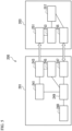
- FIG. 3 is a functional block diagram of the wireless power supply system according to the first embodiment of the present invention.
- the power transmitter 101 includes an AC power output portion 141, a power transmission portion 143, a power-transmission-side detector 145, a power-transmission-side communication portion 147, a storage portion 148, and a power-transmission-side controller 149.
- the AC power output portion 141 is coupled to the power transmission portion 143
- the power transmission portion 143 is coupled to the power-transmission-side detector 145
- the power-transmission-side controller 149 is coupled to the AC power output portion 141, the power-transmission-side detector 145, the power-transmission-side communication portion 147 and the storage portion 148.
- the AC power output portion 141 can also be provided outside of the power transmitter 101.
- each functional block is realized by hardware.
- the function of the power transmission portion 143 can be realized by a power-transmission device
- the function of the power-transmission-side detector 145 can be realized by a power-transmission-side detection device
- the function of the power-transmission-side communication portion 147 can be realized by a power-transmission-side communication device
- the function of the storage portion 148 can be realized by a memory
- the function of the power-transmission-side controller 149 can be realized by a power-transmission-side control device.
- the AC power output portion 141 is equivalent to the power source 111 of FIG. 1 , and outputs AC power.
- the power transmission portion 143 is equivalent to the power-transmitting coil 113 and the element 115 of FIG. 1 , and sends electric power to a power receiving portion 151 of the power receiver 103 described later.
- the power-transmission-side detector 145 is a current sensor that detects the current I 1 flowing through the power-transmitting coil 113, as a value indicating the power-transmission situation of the power transmission portion 143, and sends data of the detected current to the power-transmission-side controller 149.
- An example of the current sensor capable of being used includes a sensor that measures a magnetic field, generated in the vicinity of a power cable through which a current passes, on the basis of a Hall effect, or a sensor that has a resistor inserted into a power cable through which a current passes and measures a potential drop occurring in this resistor.
- the power-transmission-side communication portion 147 performs radio communication with a power-receiving-side communication portion 155 described later.
- a system of communication between the power-transmission-side communication portion 147 and the power-receiving-side communication portion 155 is, for example, radio communication using radio waves of ZigBee (Registered Trademark), Bluetooth (Registered Trademark) or the like, or optical communication using an optical signal.
- the power-transmission-side communication portion 147 includes an antenna.
- the power-transmission-side communication portion 147 includes a light emitting element or a light receiving element for communication.
- the storage portion 148 stores various information such as information relating to the coupling coefficient or the impedance (value such as L 1 or L 2 ) of the element, a program which describes each function of the power-transmission-side controller 149 described later, and the like, and is constituted by a volatile recording medium such as a random access memory (RAM) or a non-volatile recording medium such as a read only memory (ROM).
- the information relating to the coupling coefficient refers to, for example, information required for specifying the coupling coefficient between the power-transmitting coil 113 and the power-receiving coil 121, or information of a combination of the frequency f with the coupling coefficient k when Formula (12) is satisfied.
- the power-transmission-side controller 149 controls and manages each functional block of the power transmitter 101, and the entirety of the power transmitter 101.
- the power-transmission-side controller 149 is constituted by, for example, any suitable processor such as a central processing portion (CPU), or a dedicated processor (for example, digital signal processor (DSP)) specialized for each process. Specific processes which are performed by the power-transmission-side controller 149 will be described later.
- the power receiver 103 includes a power receiving portion 151, a power-receiving-side detector 153, a power-receiving-side communication portion 155, and a power-receiving-side controller 157.
- the power receiving portion 151 is coupled to the power-receiving-side detector 153, and the power-receiving-side detector 153 and the power-receiving-side communication portion 155 are coupled to the power-receiving-side controller 157.
- the function of each functional block is realized by hardware.
- the function of the power receiving portion 151 can be realized by a power receiving device
- the function of the power-receiving-side detector 153 can be realized by a power-receiving side detection device
- the function of the power-receiving-side communication portion 155 can be realized by a power-receiving-side communication device
- the function of the power-receiving-side controller 157 can be realized by a power-receiving-side control device.
- the power receiver 103 also includes a storage portion that stores a program which describes each function of the power-receiving-side controller 157, and the like, but the storage portion is not shown in the drawing.
- the power receiving portion 151 is equivalent to the power-receiving coil 121 and the element 123 of FIG. 1 , receives electric power transmitted from the power transmission portion 143, and supplies the electric power to the load 125.
- the power-receiving-side detector 153 is a current sensor that detects the current I 2 flowing through the power-receiving coil 121, as a value indicating the power-receiving situation of the power receiving portion 151, and sends data of the detected current to the power-receiving-side controller 157.
- An example of the current sensor capable of being used includes a sensor that measures a magnetic field, generated in the vicinity of a power cable through which a current passes, on the basis of a Hall effect, or a sensor that has a resistor inserted into a power cable through which a current passes and measures a potential drop occurring in this resistor.
- the power-receiving-side communication portion 155 performs radio communication with the power-transmission-side communication portion 147.
- the power-receiving-side communication portion 155 includes an antenna.
- the power-receiving-side communication portion 155 includes a light emitting element or a light receiving element for communication.
- the power-receiving-side controller 157 controls and manages each functional block of the power receiver 103, and the entirety of the power receiver 103.
- the power-receiving-side controller 157 is constituted by, for example, any processor such as a CPU or a DSP. Specific processes which are performed by the power-receiving-side controller 157 will be described later.
- a coupling coefficient when there is no positional misalignment is denoted by k 1
- a frequency satisfying Formula (12) in that case is denoted by f 1 .
- the storage portion 148 stores these values in association with each other.
- the power-transmission-side controller 149 controls the AC power output portion 141 so as to output AC power of the frequency f 1 equivalent to the absence of the positional misalignment.
- the power transmission portion 143 sends this AC power to the power receiving portion 151.
- the power-transmission-side detector 145 detects the current I 1 flowing through the power-transmitting coil 113, and sends its data to the power-transmission-side controller 149.
- the power-receiving-side detector 153 detects the current I 2 flowing through the power-receiving coil 121, and sends its data to the power-receiving-side controller 157.
- the power-receiving-side controller 157 controls the power-receiving-side communication portion 155 so as to transmit the received current data to the power transmitter 101.
- the power-transmission-side communication portion 147 receives current data from the power-receiving-side communication portion 155, and sends the current data to the power-transmission-side controller 149.
- the power-transmission-side controller 149 reads out the values of L 1 and L 2 stored in the storage portion 148, and determines whether Formula (12) is established, from the read-out values of L 1 and L 2 and the received data of I 1 and I 2 .
- the power-transmission-side controller 149 determines that the power-transmitting coil 113 and the power-receiving coil 121 have a desired positional relationship, and that there is no positional misalignment therebetween.
- the power-transmission-side controller 149 controls the AC power output portion 141 so as to continue to output the AC power of the frequency f 1 without changing a frequency.
- the power-transmission-side controller 149 reads out the value of the coupling coefficient k 1 which is stored in the storage portion 148, determines a coupling coefficient k 2 after the positional misalignment by Formula (23), and calculates a frequency f 2 satisfying Formula (12) at the coupling coefficient k 2 , from Formula (13).
- the power-transmission-side controller 149 controls the AC power output portion 141 so as to output the AC power of this frequency f 2 .
- the storage portion 148 stores a relationship between the coupling coefficient and power reception in the power receiver 103, as information relating to the coupling coefficient.
- This relationship is, for example, a relationship between the coupling coefficient and power (supplied power) supplied to the load 125 when the AC power output portion 141 outputs constant electric power at a predetermined frequency (since a frequency is fixed when the coupling coefficient is determined).
- information relating to the coupling coefficient stored in the storage portion 148 is a relationship between the power reception and the coupling coefficient, but there is no limitation to such an aspect.
- a parameter having a correlation with the coupling coefficient can be arbitrarily used.
- the parameter having a correlation with the coupling coefficient is, for example, the current Iz of the power-receiving coil 121.
- the power-receiving-side detector 153 is a voltage sensor and a current sensor that detect a voltage which is applied to the load 125 and a current which is input to the load 125, as a power-receiving situation. Meanwhile, a detection location is not limited load 125, and the power-receiving-side detector 153 may measure a voltage and a current relating to the element 123. In addition, a detection target is not limited to the voltage and the current, and the detection target may be a power. In this case, the power-receiving-side detector 153 is a power sensor.
- An example of the voltage sensor includes a sensor that divides a voltage using a resistor and converts the voltage into a digital value using an AD converter.
- an example of the power sensor includes a sensor that measures a voltage and a current using the voltage sensor and the current sensor, and temporally averages a value obtained by multiplying the voltage and the current together to determine electric power.
- the power receiving portion 151 receives this electric power, and the power-receiving-side detector 153 detects a voltage and a current relating to the load 125 and sends its data to the power-receiving-side controller 157.
- the power-receiving-side controller 157 calculates a power value which is charged (consumed) in the load 125 from the received data.
- the power-receiving-side controller 157 controls the power-receiving-side communication portion 155 so as to transmit this power value data to the power transmitter 101.
- the power-transmission-side communication portion 147 receives the power value data from the power-receiving-side communication portion 155.
- the power-transmission-side controller 149 reads out the relationship between the power reception and the coupling coefficient which are stored in the storage portion 148, and determines whether the read-out power value corresponding to the coupling coefficient k 1 and the received power value data are coincident with each other. Meanwhile, the wording "coincident with each other" is not limited strictly to the establishment of the equality, and the power-transmission-side controller 149 can also regard the read-out power value and the received power value as being coincident with each other insofar as the difference therebetween is in an error range which is determined in advance.
- the power-transmission-side controller 149 determines that the power-transmitting coil 113 and the power-receiving coil 121 have a desired positional relationship, and that there is no positional misalignment therebetween.
- the power-transmission-side controller 149 controls the AC power output portion 141 so as to continue to output the AC power of the frequency f 1 without changing the frequency.
- the power-transmission-side controller 149 determines that the relative positional relationship between the power-transmitting coil 113 and the power-receiving coil 121 deviates from a desired position, and specifies the coupling coefficient k 2 corresponding to the received power value data from the relationship (for example, relationship between the power reception and the coupling coefficient) stored in the storage portion 148.
- the power-transmission-side controller 149 calculates a frequency f 2 satisfying Formula (12) at the coupling coefficient k 2 , and controls the AC power output portion 141 so as to output the AC power of this frequency f 2 .
- the frequency f and the imaginary impedance jZ S2i of the element 123 are determined so that the impedance Zs of the power-receiving side seen from the power source 111 is independent of the coupling coefficient k, on the basis of satisfying the Formula (12). That is, in the present embodiment, the wireless power supply system 100 satisfies Formula (12), thereby the impedance Zs is represented by the real impedance Z 2r and the imaginary impedances jZ S1i and jZ S2i of the load 125, and is independent of the coupling coefficient k.
- the power-transmission-side controller 149 selects the frequency f so that Formula (12) is established. That is, the power-transmission-side controller 149 is configured to perform the following.
- the power-transmission-side controller 149 regulates the frequency f so that the impedance Z S of the power-receiving side seen from the power source 111 is independent of the coupling coefficient k.
- the element 115 of the power transmitter 101 and the element 123 of the power receiver 103 can be set so as to satisfying Formula (20).
- the impedance Z S does not have an imaginary part, and not only the impedance Z S of the power-receiving side seen from the power source 111 is independent of the coupling coefficient, but also the power factor of the power source 111 is 100%. Thus, it is possible to maximize a power-transmission efficiency in the power source 111.
- the impedance of the power-transmission side seen from the power-receiving side is also determined to pure resistance (resistance having none of inductance and capacitance)
- electric power can be transmitted from the load 125 to the power source 111 with the same efficiency as the efficiency of power transmission from the power source 111 to the load 125. That is, it is possible to perform bidirectional power transmission.
- designing the wireless power supply system 100 so that Formula (12) is established has an advantage when mutual compatibility between a plurality of power receivers or between a plurality of power transmitters is secured.
- a description will be given of a case where the power transmitter 101 and the power receiver 103 where Formula (12) is established are designed, and a power receiver (second power receiver) for supplying electric power to a load (second load) of impedance Z 2ra different from the load 125 is required to be designed (the circuit configuration of the second power receiver is the same as that of the power receiver 103, and only the element impedance of the second power receiver is different from that of the power receiver 103).
- the impedance Z S of the power-receiving side seen from the power source 111 is determined to a value represented by Formula (16). That is, the second power receiver is realized so that Formula (24) and Formula (25) are established, and thus the impedance of the power-receiving side seen from the power source 111 can be kept constant without changing the power transmitter 101. Thereby, even when the impedance of the load changes, a wireless power supply system in which a voltage on the power-transmission side is likely to fluctuate can be constructed through a simple design change.
- a power transmitter (hereinafter, second power transmitter) to which the voltage V Sa is supplied can be configured through a simple design change (the circuit configuration of the second power transmitter is the same as that of the power transmitter 101, and only the element impedance of the second power transmitter is different from that of the power transmitter 101).
- the impedance Z Sa of the power-receiving side seen from the second power source is required to satisfy Formula (26).
- the second power transmitter is realized so that Formula (27) and Formula (28) are established, and thus a constant voltage can be supplied to the load 125 without changing the power receiver 103.
- a wireless power supply system in which a voltage on the power-transmission side is likely to fluctuate can be constructed through a simple design change.
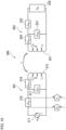
- a wireless power supply system 200 includes a power transmitter 201 and a power receiver 203.
- the power transmitter 201 includes a power-transmitting coil 213 to which AC power is input from a power source 211, an element (power-transmission-side series element) 215, and an element (power-transmission-side parallel element) 217.
- the power receiver 203 includes a power-receiving coil 221, an element (power-receiving-side series element) 223, and an element (power-receiving-side parallel element) 227.
- a load 225 is coupled in series to the element 223.
- components 211, 213, 215, 221, 223, and 225 are the same as the components 111, 113, 115, 121, 123, and 125, respectively, of the power transmitter 101 and the power receiver 103 according to the first embodiment, and thus the description will not be repeated.
- the following description shows that the impedance Z S (impedance which does not include the power source 211) of the power-receiving side seen from the power source 211 is independent of the coupling coefficient in the circuit of FIG. 4 . Meanwhile, as shown in FIG.
- the wireless power supply system 200 includes an AC power output portion 241, a power transmission portion 243, a power-transmission-side detector 245, a power-transmission-side communication portion 247, a storage portion 248, a power-transmission-side controller 249, a power receiving portion 251, a power-receiving-side detector 253, a power-receiving-side communication portion 255 and a power-receiving-side controller 257.
- the functions of the respective function portions are the same as the functions of the function portions according to the first embodiment which correspond thereto, and thus the description will not be repeated.
- the same method as that in the first embodiment can also be used.
- the element 217 is coupled in parallel to the power-transmitting coil 213 and coupled to the power-transmitting coil side rather than the element 215, and has imaginary impedance jZ P1i . That is, the element 217 is coupled in parallel to the power-transmitting coil 213 at a position closer to the power-transmitting coil 213 than the element 215, and has imaginary impedance jZ P1i . To express such a coupling relationship in other words, the element 215 is coupled in series to the power-transmitting coil 213 at a position closer to the power source 211 than the element 217.
- the element 227 is coupled in parallel to the power-receiving coil 221 and coupled to the power-receiving coil side rather than the element 223, and has imaginary impedance jZ P2i . That is, the element 227 is coupled in parallel to the power-receiving coil 221 at a position closer to the power-receiving coil 221 than the element 223, and has imaginary impedance jZ P2i .
- the elements 217 and 227 are constituted, for example, by a reactance element such as an inductor (reactor, coil) or a capacitor, or a plurality of elements of a combination of such elements.
- each parameter of the wireless power supply system 200 is determined or controlled so that Formula (12) is established.
- the result of determining the impedance Z 1 (impedance which includes the element 217) of the power-receiving side seen from the element 217 is determined to a value represented by Formula (30), and this formula does not contain the coupling coefficient k.
- Z 1 L 1 L 2 Z P 1 i Z P 2 i Z 2 r ⁇ jZ S 2 i Z P 1 i Z P 2 i + Z P 1 i ⁇ L 1 L 2 Z P 2 i Z S 2 i + jZ 2 r
- Formula (31) L 1 L 2 Z P 2 i
- Formula (32) is established from Formula (30) and Formula (31).
- Z P 1 i L 1 L 2 Z P 2 i
- Z 1 L 1 L 2 Z 2 r ⁇ jZ S 2 i
- the impedance Z S of the power-receiving side seen from the power source 211 is determined to a value represented by Formula (33).
- Z S L 1 L 2 Z 2 r + j L 2 L 1 Z S 1 i ⁇ Z S 2 i
- the impedance Z S of the power-receiving side seen from the power source 211 is represented by the real impedance Z 2r of the load 225 on the power-receiving side and the imaginary impedances jZ S1i and jZ S2i of the elements 215 and 223. Since the real impedance Z 2r of the load 225 and the imaginary impedances jZsii and jZ S2i are independent of the coupling coefficient k, the impedance Zs is also independent of the coupling coefficient k.
- a real part of the impedance Zs is represented only by the impedance of the load 225 and self-inductances of the power-transmitting coil 213 and the power-receiving coil 221, and is not influenced by impedances of the elements 215, 217, 223 and 227.
- the circuit of FIG. 4 is constituted by more specific circuit elements.
- the elements 215 and 223 are constituted by inductors (having self-inductances of L S1 and L S2 ), and the elements 217 and 227 are constituted by capacitors (having capacitances of C P1 and C P2 ).
- Formula (37) a relationship between the self-inductances of the elements 215 and 223 is represented by Formula (37) from Formula (34).
- Formula (12), Formula (36) and Formula (37) the power factor of the power source 211 is 100%.
- L S 1 L 1 L 2 L S 2
- Formula (39) When Formula (38) satisfies Formula (12), Formula (39) is established. Meanwhile, the asterisk "*" in Formula (39) indicates a complex conjugate.
- k 2 j ⁇ L 2 + 1 j ⁇ C P 2 Z 2 r + j ⁇ L S 2 Z 2 r + j ⁇ L S 2 + 1 j ⁇ C P 2 j ⁇ L 2 + 1 j ⁇ C P 2 Z 2 r + j ⁇ L S 2 Z 2 r + j ⁇ L S 2 + 1 j ⁇ C P 2 ⁇ ⁇ 2 L 2 2
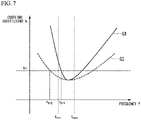
- the coupling coefficient k is a function of an angular frequency ⁇ (that is, frequency f), and this function is represented by a solid-line graph G1 of FIG. 7 .
- a broken-line graph G2 of FIG. 7 which is a comparison target indicates a result in a case the element 223 of the power receiver 203 is constituted by only the capacitor rather than the inductor.
- the element 223 being constituted by the inductor rather than the element 223 being constituted by only the capacitor obtains a result of the magnitude of the inclination of the graph becoming larger, that is, the change range of the coupling coefficient k satisfying Formula (12) becomes larger by changing the frequency f.
- variable range (f min (lower limit) ⁇ f ⁇ f max (upper limit)) of the frequency f is determined, and this variable range is determined as in FIG. 7 with respect to the graphs G1 and G2.
- the variable range is determined by, for example, the upper and lower limits of the frequency range of power capable of being output by the power source 211.
- a frequency f 3-1 satisfying Formula (12) is included within the variable range in the graph G1.
- a frequency f 3-2 satisfying Formula (12) lies outside of the variable range. That is, when the power-receiving-side series element 223 of the power receiver 203 is constituted by the inductor, a frequency satisfying Formula (12) is more likely to be present within the variable range than when the element is constituted by the capacitor even when the coupling coefficient changes greatly. Thereby, it is possible to change a frequency while suppressing fluctuation in an AC voltage from the power source 211, in response to a change in the coupling coefficient in a wider range.
- the shape of the graph G1 changes with a change in a setting value.
- the change range of the coupling coefficient k becomes larger than when the minimum value of the coupling coefficient is located in the variable range.
- the variable range of the frequency f is located in a region (in FIG. 8 , a monotonically decreasing region, or the left side of the minimum value) having a larger absolute value of an inclination.
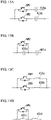
- the impedances of the element 223 and element 227 are determined so that the coupling coefficient is determined to the upper limit k max or the lower limit k min of the fluctuation range when the frequency is the upper limit f max or the lower limit f min of the variable range, as shown in FIGS. 9A through 9D .
- the imaginary impedances of the element 223 and element 227 are determined so as to satisfy Formula (12) when the frequency is the upper limit f max or the lower limit f min of the variable range, and the coupling coefficient is the upper limit k max or the lower limit k min of the fluctuation range.
- Formula (12) as the self-inductances of the power-transmitting coil 213 and the power-receiving coil 221, any of values in the changing range of the self-inductance which depends on change in the coupling coefficient k within the fluctuation range is used. By making such a determination, it is possible to increase the possibility of the frequency f satisfying Formula (12) being present when the coupling coefficient changes. Meanwhile, FIG.
- FIG. 9A shows a case where the coupling coefficient is determined to the lower limit k min of the fluctuation range when the frequency is the upper limit f max of the variable range.
- FIG. 9B shows a case where the coupling coefficient is determined to the lower limit k min of the fluctuation range when the frequency is the lower limit f min of the variable range.
- FIG. 9C shows a case where the coupling coefficient is determined to the upper limit k max of the fluctuation range when the frequency is the lower limit f min of the variable range.
- FIG. 9D shows a case where the coupling coefficient is determined to the upper limit k max of the fluctuation range when the frequency is the upper limit f max of the variable range.
- a change control method of a frequency can be performed more easily than the method described in the first embodiment.
- the method in the first embodiment is a method of determining the coupling coefficient k 2 after a change from Formula (23), and calculating the frequency f 2 satisfying Formula (12) from Formula (13).
- a description will be given of a method of determining the frequency f 2 without using Formula (13).
- the power-transmission-side controller 249 determines ⁇ on the basis of the values of currents I 1 and I 2 detected by the power-transmission-side detector 245 and the power-receiving-side detector 253, and performs PID control on a difference between ⁇ and 1. Since the polynomial of Formula (13) is not required to be solved, it is possible to limit the computational load of the power-transmission-side controller 249.
- the frequency f, the coupling coefficient k, and the imaginary impedance of the power-receiving-side series element 223 satisfy Formula (12), and thus the impedance Zs of the power-receiving side seen from the power source 211 is independent of the coupling coefficient k.
- the power-transmission-side parallel element 217 and the power-receiving-side parallel element 227 satisfy Formula (31), and thus the impedance Z S is represented by the same formula as that in the first embodiment and is not influenced by the impedance values of the elements 217 and 227.
- the frequency f can be selected so that Formula (12) is established. That is, the power-transmission-side controller 249 is configured to regulate the frequency f so that the impedance Zs of the power-receiving side seen from the power source 211 is independent of the coupling coefficient k, when the coupling coefficient k changes.
- the frequency f a case does not occur in which the impedance Zs changes due to a change in the coupling coefficient k, and thus it is possible to suppress fluctuation in the impedance Z S .
- the power-receiving-side series element 223 can be constituted by the inductor.
- the power-receiving-side series element 223 plays a role in a harmonic reduction filter, and thus the waveform of an alternating current which is supplied to the load 225 can be brought close to an ideal sine wave.
- the power-receiving-side series element 223 can be constituted by the inductor, and the power-receiving-side parallel element 227 can be constituted by the capacitor.
- the magnitude of the inclination of the graph indicating a relationship between the frequency f and the coupling coefficient k satisfying Formula (12) can be made larger than when both the power-receiving-side series element 223 and the power-receiving-side parallel element 227 are constituted by the capacitors.
- a power transmitter may include an element 319 which is coupled in series to a power-transmitting coil 313 and coupled to the power-transmitting coil side rather than a power-transmission-side parallel element 317
- a power receiver may include an element 329 which is coupled in series to a power-receiving coil 321 and coupled to the power-receiving coil side rather than a power-receiving-side parallel element 327.
- the element 319 is coupled in series to the power-transmitting coil 313 at a position closer to the power-transmitting coil 313 than the power-transmission-side parallel element 317.
- the element 329 is coupled in series to the power-receiving coil 321 at a position closer to the power-receiving coil 321 than the power-receiving-side parallel element 327.
- the elements 319 and 329 include imaginary impedances jZ S1i-2 and jZ S2i-2 , respectively.
- each of the elements 315 and 323 is an inductor, and each of the elements 317, 319, 327, and 329 is a capacitor.
- a further element may be coupled in parallel or series to the power-transmitting coil 313 between the power-transmission-side series element 315 and the power-transmitting coil 313, and a further element (not shown) may be coupled in parallel or series to the power-receiving coil 321 between the power-receiving-side series element 323 and the power-receiving coil 321.
- the impedance Zs can be made independent of the coupling coefficient k.
- the element configurations of the power transmitter 301 and the power receiver 303 may be set to be symmetric with respect to each other on the basis of the power-transmitting coil 313 and the power-receiving coil 321 (line-symmetric with respect to a straight line which is located in the middle of the power-transmitting coil 313 and the power-receiving coil 321 of FIG. 10 and is orthogonal to the power-transmission direction of both the coils), and the impedance of the element on the power-transmission side may be (L 1 /L 2 ) times the impedance of the symmetric element on the power-receiving side (see Formula (40)).
- Z S 1 i ⁇ 2 L 1 L 2
- a fluctuation in the impedance Z 2r of the load is not considered.
- the impedance Z 2r of the load fluctuates depending on the state of charge (SOC) of the battery.
- SOC state of charge
- the real part of the impedance Z S of the power-receiving side seen from the power source represented by Formula (16) or Formula (33) changes according to a fluctuation in the impedance Z 2r of the load.
- the impedance Zs being independent of the coupling coefficient is the same as that in the aforementioned embodiments.
- the capacitances of the elements 215, 217, 223, and 227 are denoted by Csi, C P1 , C S2 , and C P2 , respectively. Meanwhile, some of these elements may be constituted by inductors.
- the presence of the singular solution is not limited to the circuit configuration of FIG. 4 , and a singular solution can be determined likewise in the circuit configuration of FIG. 10 .
- a predetermined frequency and a predetermined coupling coefficient are substituted into Formula (43), to thereby obtain the impedance of the element in which the predetermined frequency and the predetermined coupling coefficient are the singular solution.
- the value of the predetermined frequency substituted into Formula (43) is determined to the upper limit f max or the lower limit f min of the variable range, and the value of the predetermined coupling coefficient is determined to the lower limit k min of the fluctuation range. In this manner, the singular solution can be arranged at the boundary of the variable range.
- FIGS. 11A and 11B describe a change in the shape of a graph of the coupling coefficient k and the frequency f when the impedance Z 2r of the load 225 fluctuates.
- a description will be given of a case where a singular solution S 1 is within the variable range of the frequency f (except the boundary), and is within the fluctuation range of the coupling coefficient k (except the boundary).
- the graph of the coupling coefficient k and the frequency f changes from a graph G3 to a graph G4.
- the impedance Z S of the power-receiving side seen from the power source 111 is determined to a capacitive load.
- the power source 111 is constituted by an inverter circuit, it is not possible to realize soft switching.
- a singular solution S2 is the upper limit f max of the variable range of the frequency f, and is the lower limit k min of the fluctuation range of the coupling coefficient k.
- the graph of the coupling coefficient k and the frequency f changes from the graph G3 to a graph G5.
- a frequency fs-i satisfying Formula (12) is found by reducing the frequency in the graph G3.
- a frequency f 5-2 satisfying Formula (12) is also found by reducing the frequency.
- each of the elements 223 and 227 of the circuit configuration shown in FIG. 4 is a capacitor, and the capacitances of the elements 223 and 227 are denoted by C S2 and C P2 , respectively.
- An electromotive force V m is induced to the power-receiving coil 221 by magnetic coupling to the power-transmitting coil 213, and the power receiver 203 is represented by an equivalent circuit as shown in FIG. 12 .
- the electromotive force V m is represented by Formula (44).
- V m j ⁇ k L 1 L 2 I 1
- Formula (46) is derived.
- I 2 ⁇ ⁇ 2 C S 2 2 Z 2 r + j ⁇ ⁇ 2 C S 2 2 C P 2 Z 2 r 2 1 ⁇ ⁇ 2 L 2 C P 2 + C S 2 + C P 2 1 ⁇ ⁇ 2 L 2 C S 2 + C P 2 1 ⁇ ⁇ 2 L 2 C S 2 + C P 2 2 + ⁇ 2 C S 2 2 Z 2 r 2 1 ⁇ ⁇ 2 L 2 C P 2 V m
- a phase difference between the electromotive force induced to the power-receiving coil 221 and the current I 2 of the power-receiving coil 221 may be brought close to 0°.
- the efficiency inside the power receiver becomes largest. This is equivalent to a case where Formula (47) is established.
- Formula (47) is established.
- ⁇ 2 C S 2 2 C P 2 Z 2 r 2 1 ⁇ ⁇ 2 L 2 C P 2 + C S 2 + C P 2 1 ⁇ ⁇ 2 L 2 r C S 2 + C P 2 0
- a conditional formula for increasing the efficiency inside the power receiver is derived in the circuit configuration of FIG. 10 in a similar manner without being derived with the limitation of the circuit configuration of FIG. 4 .
- each of the elements 323, 327, and 329 of the circuit configuration of FIG. 10 is a capacitor, and the capacitances of the elements 323, 327, and 329 are denoted by C S2 , C P2 , and C Sf2 , respectively.
- Formula (12) is established, Formula (48) is established similarly to Formula (41), and Formula (49) to which a singular solution is given is obtained from Formula (48).
- Formula (50) is obtained as the maximum efficiency condition.
- variables are three impedances of the elements 323, 327, and 329, and conditional formulas are total three of two formulas in Formula (49) and one formula in Formula (50), each of the impedances of the elements 323, 327, and 329 satisfying the maximum efficiency condition is determined to a specific value while the singular solution is determined to a desired value.
- each separate condition other than the maximum efficiency condition for setting any characteristics by combining this separate condition and Formula (49), and the impedance of an element satisfying the separate condition is determined while the singular solution is determined to a desired value.
- each of the impedances of the elements 323 and 327 satisfying Formula (49) is determined to a specific value. Therefore, when it is difficult to define a desired condition as a formula, it is possible to confirm whether the desired condition is satisfied in a case where the impedance of the element 329 is a certain value. When the desired condition is not satisfied, it is possible to adjust the impedance of the element 329 so that the desired condition is satisfied by changing the impedance of the element 329.
- the impedance of the element is fixed and does not change, but the present invention is not limited to such an aspect.
- the element of the power receiver may be constituted by a variable element (variable inductor or variable capacitor).
- the impedance of the power-receiving side seen from the power source can made to be independent of the coupling coefficient by changing the impedance (imaginary impedance) of the element of the power receiver rather than the frequency f, or by changing the impedance (imaginary impedance) of the element of the power receiver as well as the frequency f when the coupling coefficient k changes.
- the control of change in the imaginary impedance of the element may be performed by the aforementioned power-transmission-side controller.
- the power-transmission-side controller is configured to perform the following. Specifically, when the coupling coefficient k changes, the power-transmission-side controller can specify the value of the imaginary impedance of the element so that the impedance of the power-receiving side seen from the power source is independent of the coupling coefficient k. The power-transmission-side controller can instruct the power-receiving-side controller to set the imaginary impedance of the element to this value through the communication portion.
- the frequency or the imaginary impedance of the element is controlled and changed by the transmission-side controller.
- the aforementioned power-receiving-side controller may be configured to control and change the frequency or the imaginary impedance of the element.
- the power-receiving-side controller may acquire information required to the control from the transmission-side controller through the aforementioned communication portion. That is, when the coupling coefficient k changes, the power-receiving-side controller can specify the value of the frequency of AC power which is output by the power source so that the impedance of the power-receiving side seen from the power source is independent of the coupling coefficient k. The power-receiving-side controller can instruct the power-transmission-side controller to set the frequency of the AC power which is output by the power source to this value.
- the power-receiving-side controller may regulate the imaginary impedance of the element of the power receiver so that the impedance of the power-receiving side seen from the power source is independent of the coupling coefficient k.
- the wireless power supply system of the present invention may be configured such that operational effects of the embodiment or the modification example are obtained. Therefore, when the coupling coefficient k changes, the wireless power supply system of the present invention may be configured to regulate at least one of the frequency of the AC power which is output by the power source and the imaginary impedance of the element so that the impedance of the power-receiving side seen from the power source is independent of the coupling coefficient k.
- an example of a variable capacitor or a variable inductor is a circuit in which a plurality of capacitors 431a through 431d or inductors 433a through 433d having different impedances are coupled to each other through switching elements SW1 to SW6.
- the value of the capacitance or inductance of the circuit changes, and thus a relationship between the frequency f and the coupling coefficient k satisfying Formula (12) changes.
- variable capacitor or the variable inductor may include not only a circuit in which the value of capacitance or inductance changes selectively and discontinuously as shown in FIGS. 13A through 13D , but also a circuit in which the above value changes continuously as in a variable transformer, a trimmer capacitor or the like.
- the voltage or the current in the wireless power supply system is a sine wave.
- the present invention can be applied to a fundamental wave component.
- the resistive components are disregarded to consider the power-transmitting coil, the power-receiving coil and each element as ideal inductance (coil) or capacitance, and thus the present invention can be used. Further, even when the resistive components and reactance components are present in wirings within the wireless power supply system, these resistive components and reactance components are disregarded, and thus the present invention can be used.
- wireless power supply system examples include charging systems or driving systems of moving objects, home electric appliances or medical instruments, but the present invention is not limited to such an aspect.
- the present invention can be applied to, for example, various circuit devices which use the principle of electromagnetic induction of coils.
- the wireless power supply system of the present invention can be incorporated into an insulation-type DC-DC converter.
- each parameter (the impedance of an element and the frequency) of the wireless power supply system is determined so that Formula (12) is established, but the present invention is not limited to such an aspect.
- each parameter (the impedance of an element and the frequency) of the wireless power supply system may be determined so that Formula (51) is established.
- I 2 I 1 K I L 1 L 2
- Each parameter (the impedance of the element, the frequency, and the coupling coefficient) of the wireless power supply system 100 is determined or controlled so that Formula (51) is established.
- Formula (52) is substituted into Formula (14), and thus Formula (14) becomes Formula (53).
- Z 1 L 1 L 2 K I 2 Z 2 r ⁇ j K I 2 Z S 2 i + K I 2 ⁇ 1 ⁇ L 2
- the impedance Zs of the power-receiving side seen from the power source 111 is represented by Formula (54).
- Z S L 1 L 2 K I 2 Z 2 r + j L 2 L 1 Z S 1 i ⁇ K I 2 Z S 2 i + K I 2 ⁇ 1 ⁇ L 2
- the impedance Zs of the power-receiving side seen from the power source 111 does not contain the coupling coefficient k. Therefore, the impedance Z S is independent of the coupling coefficient k. That is, even when the coupling coefficient changes, the frequency f is selected (determined) so that Formula (51) is established, and thus the impedance Z S is independent of the coupling coefficient k. That is, since the coefficient K I is constant and does not change, the right side of Formula (51) is a constant value. Therefore, the frequency f and the imaginary impedance Z S2i are determined so that the ratio of Iz to I 1 keeps constant even when the coupling coefficient changes.
- the impedance Zs and the AC voltage Vs are not likely to fluctuate.
- the impedance Z S2i of the element 123 rather than the frequency f may be changed so that Formula (51) is established. That is, when the frequency f, the imaginary impedance Z S2i and the coupling coefficient k are values which satisfy Formula (51), the impedance Zs is independent of the coupling coefficient k.
- the impedance Z 1 of the power-receiving side seen from the power-transmitting coil 113 is represented by Formula (58)
- the impedance Zs of the power-receiving side seen from the power source 111 is represented by Formula (59).
- Formula (59) becomes Formula (60).
- shifting of the frequency f from a value which satisfies Formula (51) means that it is possible to control the real part of the impedance Z S and the power factor.
- the frequency f so that Formula (57) is satisfied, constant electric power can be supplied to the load 125 even when the parameters (for example, the inductances Li and L 2 ) fluctuate or the load 125 fluctuates.
- Z S K I 2 1 + ⁇ 2 L 1 L 2 Z 2 r + jK I 2 L 1 L 2 1 ⁇ 1 + ⁇ 2 Z S 2 i + ⁇ L 2
- the circuit configuration of FIG. 14 is a circuit configuration obtained by adding an element 519 to the circuit configuration of FIG. 4 . That is, components 511, 513, 515 and 517 of a power transmitter 501 and components 521, 523 and 527 of a power receiver 503 of FIG. 14 are the same as the components 211, 213, 215 and 217 of the power transmitter 201 and the components 221, 223 and 227 of the power receiver 203 of FIG. 4 , respectively. Further, a load 525 coupled to the power receiver 503 is the same as the load 225 coupled to the power receiver 203.
- the element 519 is coupled in series to the power-transmitting coil 513 and coupled to the power-transmitting coil side rather than the element 517, and has imaginary impedance jZ S1i-2 . That is, the element 519 is coupled in series to the power-transmitting coil 513 at a position closer to the power-transmitting coil 513 than the element 517.
- the element 519 corresponds to the element 319 of FIG. 10 .
- the element 519 is constituted, for example, by a reactance element such as an inductor (reactor, coil) or a capacitor, or a plurality of elements of a combination of such elements.
- the impedance Z 1C is represented by Formula (64).
- the coefficient K I is set to a value larger than 0 and smaller than 1, or a value larger than 1.
- Z S 1 i ⁇ 2 ⁇ ⁇ L 1 1 ⁇ K I 2
- Z 1 c K i 2 L 1 L 2 jZ P 2 i Z 2 r + jZ S 2 i Z 2 r + jZ S 2 i + jZ P 2 i *
- Z 1 K I 2 L 1 L 2 Z P 1 i Z P 2 i Z 2 r + jZ S 2 i * Z P 1 i ⁇ K I 2 L 1 L 2 Z P 2 i jZ 2 r + Z S 2 i + Z P 1 i Z P 2 i
- Formula (67) is established from Formula (65) and Formula (66).
- Z P 1 i K I 2 L 1 L 2
- Z P 2 i K I 2 L 1 L 2 Z 2 r + jZ S 2 i *
- the impedance Zs (impedance which does not include the power source 511) of the power-receiving side seen from the power source 511 is determined to a value represented by Formula (68).
- Z S K I 2 L 1 L 2 Z 2 r + j 1 K I 2 L 2 L 1 Z S 1 i ⁇ Z S 2 i
- the impedance Zs of the power-receiving side seen from the power source 511 is independent of the coupling coefficient k.
- the real part of the impedance Z S is represented only by the impedance of the load 525, the self-inductances of the power-transmitting coil 513 and the power-receiving coil 521 and the coefficient K I , and is not influenced by the impedances of the elements 515, 517, 519, 523 and 527.
- Formula (72) is different from Formula (13) only in a point where the actual coupling coefficient k is changed to an apparent coupling coefficient k a . Accordingly, the aforementioned designing method and control method of a wireless power supply system based on Formula (12) can be applied to designing method and control method of a wireless power supply system based on Formula (52).
- the left side of Formula (73) is equivalent to a response magnification Q( ⁇ ) of a circuit constituted by the power receiver 103 and the load 125.
- Qc also becomes larger proportionally to Q( ⁇ 0 ). Accordingly, the establishment of Formula (12) (or Formula (73)) means that the relation of Formula (74) is also established.
- the response magnification Q( ⁇ ) of FIG. 4 is represented by Formula (75).
- Q ⁇ j ⁇ L 2 Z P 2 i 2 Z 2 r 2 + Z S 2 i + Z P 2 i 2 Z 2 r + j ⁇ L 2 + Z P 2 i Z 2 r 2 + Z S 2 i Z S 2 i + Z P 2 i Z 2 r 2 + Z S 2 i + Z P 2 i + Z P 2 i 2 i 2
- Formula (76) becomes Formula (78) from Formula (77).
- Q C I 2 I L 2 ⁇ C L 2 Z 2 r
- Formula (79) shows that the current I 2 flowing through the power-receiving coil 221 becomes larger as the coupling coefficient k becomes smaller.
- the power receiver When the wireless power supply system is applied to a charging system of an electric vehicle, for example, the power receiver is mounted on the electric vehicle. In this case, it may be desired to reduce the size of the power receiver since the installation location of the power receiver on the electric vehicle is limited.
- the conducting wire forming the power-receiving coil may be made thinner, for example.
- the conducting wire thinner the electric resistance of the conducting wire increases, and thus the calorific value increases. Accordingly, as shown in Formula (73), by setting the range of the coefficient K I to 0 ⁇ K I ⁇ 1, it is possible to reduce the current I 2 compared with a case where Formula (12) is established, and thus it is possible to reduce the calorific value.
- the range of the coefficient K I is set so as to satisfy 1 ⁇ K I .
- the wireless power supply system including the power transmitter and the power receiver is described.
- the present invention is not limited to such a configuration, and the present invention may be applied to a power receiver that receives electric power wirelessly from a power transmitter including a power-transmitting coil to which AC power of a frequency is input from a power source.
- This power receiver includes the same configuration as that of the power receiver 103, 203 or 303 described in the embodiments and the modification examples.
- the power receiver of the present invention includes a power-receiving coil magnetically coupled to the power-transmitting coil at a coupling coefficient, and a power-receiving-side series element (first power-receiving-side series element) which is coupled in series to the power-receiving coil and which has imaginary impedance jZ S2i .
- the power-receiving coil may have the same configuration as that of the power-receiving coil 121, 221 or 321, and the power-receiving-side series element may have the same configuration as that of the element 123, 223 or 323.
- the frequency of AC power which is output by the power source and the imaginary impedance of the power-receiving-side series element may be determined so that the impedance of the power-receiving side seen from the power source is independent of the coupling coefficient k when the coupling coefficient k changes.
- the power receiver of the present invention may be configured to regulate at least one of the frequency of the AC power which is output by the power source and the imaginary impedance of the power-receiving-side series element so that the impedance of the power-receiving side seen from the power source is independent of the coupling coefficient k when the coupling coefficient k changes.
- the power receiver may instruct the power source to change a frequency through a communication portion or the like.
- a wireless power supply system and a power receiver which are capable of suppressing a fluctuation in impedance of a power-receiving side seen from a power source, when a coupling coefficient changes.
Landscapes
- Engineering & Computer Science (AREA)
- Power Engineering (AREA)
- Computer Networks & Wireless Communication (AREA)
- Transportation (AREA)
- Mechanical Engineering (AREA)
- Charge And Discharge Circuits For Batteries Or The Like (AREA)
- Current-Collector Devices For Electrically Propelled Vehicles (AREA)
- Electric Propulsion And Braking For Vehicles (AREA)
Claims (15)
- Système d'alimentation électrique sans fil (300, 500) comprenant :un émetteur de courant (301, 501) ; etun récepteur de courant (303, 503),l'émetteur de courant comprenant une bobine d'émission de courant (313, 513) qui est alimentée avec un courant alternatif d'une fréquence f à partir d'une source de courant (311, 511), etle récepteur de courant (303, 503) comprenant : une bobine de réception de courant (321, 521) couplée magnétiquement à la bobine d'émission de courant (313, 513) à un coefficient de couplage k ;et un premier élément en série de côté de réception de courant (323, 523) couplé en série à la bobine de réception de courant (321, 521) et ayant une impédance imaginaire jZS2i,caractérisé en ce quele système d'alimentation électrique sans fil (300, 500) est configuré pour déterminer la fréquence, le coefficient de couplage et l'impédance imaginaire sur la base de la satisfaction de la formule suivante,
 où Li est l'auto-inductance de la bobine d'émission de courant (313, 513), L2 est l'auto-inductance de la bobine de réception de courant (321, 521), I1 est un courant circulant à travers la bobine d'émission de courant (313, 513), I2 est un courant circulant à travers la bobine de réception de courant (321, 521), et KI est un coefficient,dans lequel le coefficient KI est une valeur supérieure à 0 et inférieure à 1, ou une valeur supérieure à 1, etdans lequel :
l'émetteur de courant (301, 501) comprend en outre :un élément en parallèle de côté d'émission de courant (317, 517) couplé en parallèle à la bobine d'émission de courant (313, 513) et ayant une impédance imaginaire jZP1i ; etun premier élément en série de côté d'émission de courant (319, 519) couplé en série à la bobine d'émission de courant (313, 513) à une position plus proche de la bobine d'émission de courant (313, 513) que l'élément en parallèle de côté d'émission de courant (317, 517) et ayant une impédance imaginaire jZS1i-2 ;le récepteur de courant (303, 503) comprend en outre un élément en parallèle de côté de réception de courant (327, 527) couplé en parallèle à la bobine de réception de courant (321, 521) à une position plus proche de la bobine de réception de courant (321, 521) que le premier élément en série de côté de réception de courant (323, 523) et ayant une impédance imaginaire jZP2i ;l'impédance imaginaire du premier élément en série de côté d'émission de courant (319, 519) satisfait à la formule suivante ; et où ω est une fréquence angulaire d'une tension alternative, etles impédances imaginaires de l'élément en parallèle de côté d'émission de courant (317, 517) et de l'élément en parallèle de côté de réception de courant (327, 527) satisfont à la formule suivante :
- Système d'alimentation électrique sans fil (300, 500) selon la revendication 1, dans lequel le système d'alimentation électrique sans fil (300, 500) est configuré pour déterminer :une plage variable de la fréquence ;une plage de fluctuation du coefficient de couplage ; etles impédances imaginaires du premier élément en série de côté de réception de courant (323, 523) et de l'élément en parallèle de côté de réception de courant (327, 527) de façon à satisfaire la Formule (1), lorsque la fréquence est une limite supérieure ou une limite inférieure de la plage variable et que le coefficient de couplage est une limite supérieure ou une limite inférieure de la plage de fluctuation.
- Système d'alimentation électrique sans fil selon la revendication 2, dans lequel le système d'alimentation électrique sans fil est configuré pour déterminer les impédances imaginaires du premier élément en série de côté de réception de courant et de l'élément en parallèle de côté de réception de courant de sorte qu'une différence de phase entre une force électromotrice induite dans la bobine de réception de courant par couplage magnétique de la bobine d'émission de courant à la bobine de réception de courant et le courant de la bobine de réception de courant soit de 0°.
- Système d'alimentation électrique sans fil (300, 500) selon la revendication 2, dans lequel :une charge (325, 525) dont l'impédance fluctue est couplée au récepteur de courant (303, 503) ; etle système d'alimentation électrique sans fil (300, 500) est configuré pour déterminer des impédances imaginaires du premier élément en série de côté de réception de courant (323, 523) et de l'élément en parallèle de côté de réception de courant (327, 527) de façon à satisfaire la Formule (1) indépendamment de l'impédance de la charge (325, 525), lorsque la fréquence est la limite supérieure ou la limite inférieure de la plage variable et le coefficient de couplage est la limite inférieure de la plage de fluctuation.
- Système d'alimentation électrique sans fil (300, 500) selon l'une quelconque des revendications 1 à 4 :l'émetteur de courant (301, 501) comprend en outre un élément en série de côté d'émission de courant (315, 515) couplé en série à la bobine d'émission de courant (313, 513) à une position plus proche de la source de courant (311, 511) que l'élément en parallèle de côté d'émission de courant (317, 517) et ayant une impédance imaginaire jZsii ; etles impédances imaginaires de l'élément en série de côté d'émission de courant (315, 515) et du premier élément en série de côté de réception de courant (323, 523) satisfont à la formule suivante :

- Système d'alimentation électrique sans fil (300) comprenant :un émetteur de courant (301) ; etun récepteur de courant (303),l'émetteur de courant (301) comprenant une bobine d'émission de courant (313) qui est alimentée avec un courant alternatif d'une fréquence f à partir d'une source de courant (311), etle récepteur de courant (303) comprenant : une bobine de réception de courant (321) couplée magnétiquement à la bobine d'émission de courant (313) à un coefficient de couplage k,et un premier élément en série de côté de réception de courant (323) couplé en série à la bobine de réception de courant (321) et ayant une impédance imaginaire jZS2i,caractérisé en ce que le système d'alimentation électrique sans fil (300) est configuré pour déterminer la fréquence, le coefficient de couplage et l'impédance imaginaire sur la base de la satisfaction de la formule suivante,
 où Li est l'auto-inductance de la bobine d'émission de courant (313), L2 est l'auto-inductance de la bobine de réception de courant (321), I1 est un courant circulant à travers la bobine d'émission de courant (313), I2 est un courant circulant à travers la bobine de réception de courant (321), et KI est un coefficient,dans lequel le coefficient KI est une valeur supérieure à 0 et inférieure à 1, ou une valeur supérieure à 1, etdans lequel :
l'émetteur de courant (301) comprend en outre :un élément en parallèle de côté d'émission de courant (317) couplé en parallèle à la bobine d'émission de courant (313) et ayant une impédance imaginaire jZP1i ; etun premier élément en série de côté d'émission de courant (319) couplé en série à la bobine d'émission de courant (313) à une position plus proche de la bobine d'émission de courant (313) que l'élément en parallèle de côté d'émission de courant (317) et ayant une impédance imaginaire jZS1i-2 ;le récepteur de courant (303) comprend en outre :un élément en parallèle de côté de réception de courant (327) couplé en parallèle à la bobine de réception de courant (321) à une position plus proche de la bobine de réception de courant (321) que le premier élément en série de côté de réception de courant (323) et ayant une impédance imaginaire jZP2i ; etun deuxième élément en série de côté de réception de courant (329) couplé en série à la bobine de réception de courant (321) à une position plus proche de la bobine de réception de courant (321) que l'élément en parallèle de côté de réception de courant (327) et ayant une impédance imaginaire jZS2i-2 ;les impédances imaginaires du premier élément en série de côté d'émission de courant (319) et du deuxième élément en série de côté de réception de courant (329) satisfont à la formule suivante ; où ω est une fréquence angulaire d'une tension alternative, etles impédances imaginaires de l'élément en parallèle de côté d'émission de courant (317) et de l'élément en parallèle de côté de réception de courant (327) satisfont à la formule suivante :
- Système d'alimentation électrique sans fil (300) selon la revendication 6, dans lequel le système d'alimentation électrique sans fil (300) est configuré pour déterminer :une plage variable de la fréquence ;une plage de fluctuation du coefficient de couplage ; etles impédances imaginaires du premier élément en série de côté de réception de courant (323), du deuxième élément en série de côté de réception de courant (329) et de l'élément en parallèle de côté de réception de courant (327) de façon à satisfaire la Formule (1), lorsque la fréquence est une limite supérieure ou une limite inférieure de la plage variable et que le coefficient de couplage est une limite supérieure ou une limite inférieure de la plage de fluctuation.
- Système d'alimentation électrique sans fil (300) selon la revendication 7, dans lequel :une charge (325) dont l'impédance fluctue est couplée au récepteur de courant (303) ; etle système d'alimentation électrique sans fil (300) est configuré pour déterminer les impédances imaginaires du premier élément en série de côté de réception de courant (323), du deuxième élément en série de côté de réception de courant (329) et de l'élément en parallèle de côté de réception de courant (327) de façon à satisfaire la Formule (1) indépendamment de l'impédance de la charge (325), lorsque la fréquence est la limite supérieure ou la limite inférieure de la plage variable et le coefficient de couplage est la limite inférieure de la plage de fluctuation.
- Système d'alimentation électrique sans fil (300) selon la revendication 7 ou 8, dans lequel le système d'alimentation électrique sans fil (300) est configuré pour déterminer les impédances imaginaires du premier élément en série de côté de réception de courant (323), du deuxième élément en série de côté de réception de courant (329) et de l'élément en parallèle de côté de réception de courant (327) de sorte qu'une différence de phase entre une force électromotrice induite dans la bobine de réception de courant (321) par couplage magnétique de la bobine d'émission de courant (313) à la bobine de réception de courant (321) et le courant de la bobine de réception de courant (321) soit de 0°.
- Système d'alimentation électrique sans fil (300) selon l'une quelconque des revendications 6 à 9 :l'émetteur de courant (301) comprend en outre un deuxième élément en série de côté d'émission de courant (315) couplé en série à la bobine d'émission de courant (313) à une position plus proche de la source de courant (311) que l'élément en parallèle de côté d'émission de courant (317) et ayant une impédance imaginaire jZS1i ; etles impédances imaginaires du deuxième élément en série de côté d'émission de courant (315) et du premier élément en série de côté de réception de courant (323) satisfont à la formule suivante :

- Système d'alimentation électrique sans fil (100, 200, 300, 500) comprenant :un émetteur de courant (101, 201, 301, 501) ; etun récepteur de courant (103, 203, 303, 503),l'émetteur de courant (101) comprenant une bobine d'émission de courant (113, 213, 313, 513) qui est alimentée avec un courant alternatif d'une fréquence f à partir d'une source de courant (111, 211, 311, 511), etle récepteur de courant (103, 203, 303, 503) comprenant : une bobine de réception de courant (121, 221, 321, 521) couplée magnétiquement à la bobine d'émission de courant (113, 213, 313, 513) à un coefficient de couplage k ;et un premier élément en série de côté de réception de courant (123, 223, 323, 523) couplé en série à la bobine de réception de courant (121, 221, 321, 521) et ayant une impédance imaginaire jZS2i,caractérisé en ce que le système d'alimentation électrique sans fil (100, 200, 300, 500) est configuré pour déterminer la fréquence, le coefficient de couplage et l'impédance imaginaire sur la base de la satisfaction de la formule suivante,
 où Li est l'auto-inductance de la bobine d'émission de courant (113, 213, 313, 513), L2 est l'auto-inductance de la bobine de réception de courant (121, 221, 321, 521), I1 est un courant circulant à travers la bobine d'émission de courant (113, 213, 313, 513), I2 est un courant circulant à travers la bobine de réception de courant (121, 221, 321, 521), et KI est un coefficient, etdans lequel :l'émetteur de courant (101, 201, 301, 501) comprend en outre un élément en série de côté d'émission de courant (115, 215, 315, 515) couplé en série à la bobine d'émission de courant (113, 213, 313, 513) et ayant une impédance imaginaire jZS1i ; etles impédances imaginaires de l'élément en série de côté d'émission de courant (115, 215, 315, 515) et du premier élément en série de côté de réception de courant (123, 223, 323, 523) satisfont à la formule suivante :
 où ω est une fréquence angulaire d'une tension alternative.
 - Système d'alimentation électrique sans fil (100) selon la revendication 11, dans lequel le coefficient KI est une valeur supérieure à 0 et inférieure à 1, ou une valeur supérieure à 1.
- Système d'alimentation électrique sans fil (100, 200, 300, 500) selon l'une quelconque des revendications 1 à 10 et 12, dans lequel :le système d'alimentation électrique sans fil (100, 200, 300, 500) est configuré pour déterminer une plage de fluctuation du coefficient de couplage ; etle coefficient KI satisfait à la condition 0 < KI < 1.
- Système d'alimentation électrique sans fil (100, 200, 300, 500) comprenant :un émetteur de courant (101, 201, 301, 501) ; etun récepteur de courant (103, 203, 303, 503),l'émetteur de courant (101, 201, 301, 501) comprenant une bobine d'émission de courant (113, 213, 313, 513) qui est alimentée avec un courant alternatif d'une fréquence f à partir d'une source de courant (111, 211, 311, 511), etle récepteur de courant (103, 203, 303, 503) comprenant : une bobine de réception de courant (121, 221, 321, 521) couplée magnétiquement à la bobine d'émission de courant (113, 213, 313, 513) à un coefficient de couplage k ;et un premier élément en série de côté de réception de courant (123, 223, 323, 523) couplé en série à la bobine de réception de courant (121, 221, 321, 521) et ayant une impédance imaginaire jZS2i,caractérisé en ce que le système d'alimentation électrique sans fil (100, 200, 300, 500) est configuré pour déterminer la fréquence, le coefficient de couplage et l'impédance imaginaire sur la base de la formule suivante,
 où Li est l'auto-inductance de la bobine d'émission de courant (113, 213, 313, 513), L2 est l'auto-inductance de la bobine de réception de courant (121, 221, 321, 521), I1 est un courant circulant à travers la bobine d'émission de courant (113, 213, 313, 513), I2 est un courant circulant à travers la bobine de réception de courant (121, 221, 321, 521), et KI est un coefficient, etdans lequel :le système d'alimentation électrique sans fil (100, 200, 300, 500) est configuré pour déterminer une plage de fluctuation du coefficient de couplage ; etle coefficient KI satisfait à la condition 0 < KI < 1.
 - Système d'alimentation électrique sans fil (100, 200, 300, 500) selon l'une quelconque des revendications 1 à 14, dans lequel :le système d'alimentation électrique sans fil (100, 200, 300, 500) est configuré pour déterminer une plage de fluctuation du coefficient de couplage ; etlorsque les auto-inductances de la bobine d'émission de courant (113, 213, 313, 513) et de la bobine de réception de courant (121, 221, 321, 521) changent sur la base du changement du coefficient de couplage, les auto-inductances de la bobine d'émission de courant (113, 213, 313, 513) et de la bobine de réception de courant (121, 221, 321, 521) prennent des valeurs à l'intérieur d'une plage de changement des auto-inductances en fonction du changement du coefficient de couplage à l'intérieur de la plage de fluctuation.
Applications Claiming Priority (2)
| Application Number | Priority Date | Filing Date | Title |
|---|---|---|---|
| JP2015169841A JP6701645B2 (ja) | 2015-08-28 | 2015-08-28 | 非接触給電システム |
| PCT/JP2016/071825 WO2017038303A1 (fr) | 2015-08-28 | 2016-07-26 | Système d'alimentation électrique sans contact et dispositif de réception d'énergie |
Publications (3)
| Publication Number | Publication Date |
|---|---|
| EP3343731A1 EP3343731A1 (fr) | 2018-07-04 |
| EP3343731A4 EP3343731A4 (fr) | 2019-04-17 |
| EP3343731B1 true EP3343731B1 (fr) | 2023-02-15 |
Family
ID=58187282
Family Applications (1)
| Application Number | Title | Priority Date | Filing Date |
|---|---|---|---|
| EP16841335.9A Active EP3343731B1 (fr) | 2015-08-28 | 2016-07-26 | Système d'alimentation électrique sans contact et dispositif de réception d'énergie |
Country Status (5)
| Country | Link |
|---|---|
| US (1) | US10418858B2 (fr) |
| EP (1) | EP3343731B1 (fr) |
| JP (1) | JP6701645B2 (fr) |
| CN (1) | CN107636930B (fr) |
| WO (1) | WO2017038303A1 (fr) |
Families Citing this family (8)
| Publication number | Priority date | Publication date | Assignee | Title |
|---|---|---|---|---|
| US11467236B2 (en) * | 2019-03-12 | 2022-10-11 | Canon Medical Systems Corporation | Biological information monitoring apparatus and MRI apparatus |
| EP3939146B1 (fr) * | 2019-03-15 | 2025-09-03 | Valeo Electrification | Dispositif de transmission de puissance sans contact par couplage inductif a résonance pour recharger un véhicule automobile |
| FR3099312B1 (fr) * | 2019-07-25 | 2023-04-28 | Valeo Equip Electr Moteur | Dispositif de transmission de puissance sans contact par couplage inductif à résonance pour recharger un véhicule automobile |
| FR3099310B1 (fr) * | 2019-07-25 | 2022-12-16 | Valeo Equip Electr Moteur | Dispositif de transmission de puissance sans contact par couplage inductif à résonance pour recharger un véhicule automobile |
| FR3099313B1 (fr) * | 2019-07-25 | 2022-12-16 | Valeo Equip Electr Moteur | Dispositif de transmission de puissance sans contact par couplage inductif à résonance pour recharger un véhicule automobile |
| CN115214394B (zh) * | 2022-07-18 | 2023-04-21 | 广西电网有限责任公司电力科学研究院 | 电动汽车动态无线充电系统及横向偏移功率波动抑制方法 |
| WO2024209406A1 (fr) * | 2023-04-05 | 2024-10-10 | Auckland Uniservices Limited | Nouvelles topologies de compensation pour systèmes de transfert d'énergie sans fil |
| US12583311B1 (en) * | 2025-02-25 | 2026-03-24 | City University Of Hong Kong | Wireless in-wheel motor drive and method for optimizing the same |
Citations (1)
| Publication number | Priority date | Publication date | Assignee | Title |
|---|---|---|---|---|
| JP2015228785A (ja) * | 2014-05-07 | 2015-12-17 | 株式会社Ihi | 非接触給電システム及び受電装置 |
Family Cites Families (17)
| Publication number | Priority date | Publication date | Assignee | Title |
|---|---|---|---|---|
| US8674551B2 (en) * | 2008-06-06 | 2014-03-18 | University Of Florida Research Foundation, Inc. | Method and apparatus for contactless power transfer |
| JP2010063324A (ja) | 2008-09-07 | 2010-03-18 | Hideo Kikuchi | 誘導電力伝送回路 |
| US20120228953A1 (en) * | 2008-09-27 | 2012-09-13 | Kesler Morris P | Tunable wireless energy transfer for furniture applications |
| JP5510032B2 (ja) | 2009-05-14 | 2014-06-04 | 日産自動車株式会社 | 非接触給電装置 |
| WO2011033660A1 (fr) | 2009-09-18 | 2011-03-24 | 株式会社 東芝 | Dispositif d'alimentation electrique sans fil |
| JP5656606B2 (ja) | 2010-12-16 | 2015-01-21 | 株式会社テクノバ | 電力供給装置 |
| US20130082538A1 (en) * | 2011-09-05 | 2013-04-04 | Peter Wambsganss | Circuitry And Method For Inductive Power Transmission |
| US20130088088A1 (en) * | 2011-09-05 | 2013-04-11 | Peter Wambsganss | Circuitry And Method For Inductive Power Transmission |
| JP5927826B2 (ja) * | 2011-09-28 | 2016-06-01 | 日産自動車株式会社 | 非接触給電装置 |
| CN104604091A (zh) * | 2012-09-06 | 2015-05-06 | 松下知识产权经营株式会社 | 非接触供电系统和非接触扩展插件 |
| US9666357B2 (en) * | 2012-09-11 | 2017-05-30 | Qualcomm Incorporated | Apparatus system, and method for wirelessly receiving power using conductive structures |
| JP2015065756A (ja) * | 2013-09-25 | 2015-04-09 | 株式会社日本自動車部品総合研究所 | 受電装置および送電装置 |
| KR101604172B1 (ko) * | 2013-12-26 | 2016-03-16 | 울산대학교 산학협력단 | 전계 결합형 무선 충전장치 |
| JP6183243B2 (ja) | 2014-02-20 | 2017-08-23 | 株式会社村田製作所 | 電力伝送システム、受電装置及び送電装置 |
| CN204578220U (zh) * | 2015-02-09 | 2015-08-19 | 泰科电子(上海)有限公司 | 无线电力传输装置和包括无线电力传输装置的设备 |
| CN104779672B (zh) * | 2015-04-21 | 2016-10-12 | 东南大学 | 一种适用于电池性负载的无线充电系统 |
| CN104795878A (zh) * | 2015-05-13 | 2015-07-22 | 重庆邮电大学 | 一种无线充电汽车的阻抗自适应匹配电路设计方法 |
-
2015
- 2015-08-28 JP JP2015169841A patent/JP6701645B2/ja active Active
-
2016
- 2016-07-26 WO PCT/JP2016/071825 patent/WO2017038303A1/fr not_active Ceased
- 2016-07-26 CN CN201680032650.1A patent/CN107636930B/zh active Active
- 2016-07-26 EP EP16841335.9A patent/EP3343731B1/fr active Active
-
2017
- 2017-12-13 US US15/840,885 patent/US10418858B2/en active Active
Patent Citations (1)
| Publication number | Priority date | Publication date | Assignee | Title |
|---|---|---|---|---|
| JP2015228785A (ja) * | 2014-05-07 | 2015-12-17 | 株式会社Ihi | 非接触給電システム及び受電装置 |
Also Published As
| Publication number | Publication date |
|---|---|
| WO2017038303A1 (fr) | 2017-03-09 |
| CN107636930B (zh) | 2020-10-30 |
| JP2017046559A (ja) | 2017-03-02 |
| EP3343731A1 (fr) | 2018-07-04 |
| US20180109149A1 (en) | 2018-04-19 |
| EP3343731A4 (fr) | 2019-04-17 |
| CN107636930A (zh) | 2018-01-26 |
| US10418858B2 (en) | 2019-09-17 |
| JP6701645B2 (ja) | 2020-05-27 |
Similar Documents
| Publication | Publication Date | Title |
|---|---|---|
| EP3121933B1 (fr) | Système d'alimentation électrique sans contact et dispositif de réception de puissance | |
| US10418858B2 (en) | Wireless power supply system and power receiver | |
| EP3229343B1 (fr) | Système d'alimentation sans fil | |
| KR102110846B1 (ko) | Dc 전압 소스 사이에서의 전력의 무선 전송을 위한 장치 및 방법 | |
| EP3032701B1 (fr) | Dispositif de transmission d'énergie sans fil | |
| EP2639931B1 (fr) | Appareil de fourniture de puissance sans contact | |
| JP5880122B2 (ja) | 非接触電力伝送装置 | |
| EP2977255B1 (fr) | Dispositif de transmission de puissance électrique et dispositif de réception d'énergie électrique et véhicule comprenant celui-ci | |
| EP2763280B1 (fr) | Dispositif d'alimentation en énergie sans contact | |
| JP2011189895A (ja) | 移動体給電装置 | |
| WO2013002240A1 (fr) | Procédé de conception de système d'alimentation en énergie et système d'alimentation en énergie | |
| Mai et al. | Optimization of time-weighted average efficiency for reconfigurable IPT battery charging system | |
| JP7061058B2 (ja) | 受電機器 | |
| JP7251284B2 (ja) | 非接触給電装置 | |
| WO2014087889A1 (fr) | Appareil d'alimentation électrique sans contact et procédé permettant de commander ce dernier | |
| JP2014121113A (ja) | 送電機器及び非接触電力伝送装置 | |
| Mostafa | Enhancing Misalignment Tolerance in Inductive Power Transfer Systems: Design and Real-World Applications for Electric Mobility | |
| CN121036368A (zh) | 一种具有宽功率范围的ipt系统准谐振参数优化方法 |
Legal Events
| Date | Code | Title | Description |
|---|---|---|---|
| STAA | Information on the status of an ep patent application or granted ep patent |
Free format text: STATUS: THE INTERNATIONAL PUBLICATION HAS BEEN MADE |
|
| PUAI | Public reference made under article 153(3) epc to a published international application that has entered the european phase |
Free format text: ORIGINAL CODE: 0009012 |
|
| STAA | Information on the status of an ep patent application or granted ep patent |
Free format text: STATUS: REQUEST FOR EXAMINATION WAS MADE |
|
| 17P | Request for examination filed |
Effective date: 20171212 |
|
| AK | Designated contracting states |
Kind code of ref document: A1 Designated state(s): AL AT BE BG CH CY CZ DE DK EE ES FI FR GB GR HR HU IE IS IT LI LT LU LV MC MK MT NL NO PL PT RO RS SE SI SK SM TR |
|
| AX | Request for extension of the european patent |
Extension state: BA ME |
|
| DAV | Request for validation of the european patent (deleted) | ||
| DAX | Request for extension of the european patent (deleted) | ||
| A4 | Supplementary search report drawn up and despatched |
Effective date: 20190319 |
|
| RIC1 | Information provided on ipc code assigned before grant |
Ipc: H01F 38/14 20060101ALI20190313BHEP Ipc: B60L 5/00 20060101ALI20190313BHEP Ipc: B60M 7/00 20060101ALI20190313BHEP Ipc: H02J 50/90 20160101ALI20190313BHEP Ipc: B60L 53/12 20190101ALI20190313BHEP Ipc: H02J 50/10 20160101AFI20190313BHEP Ipc: H02J 50/12 20160101ALI20190313BHEP Ipc: H02J 50/80 20160101ALI20190313BHEP Ipc: H02J 7/00 20060101ALI20190313BHEP |
|
| STAA | Information on the status of an ep patent application or granted ep patent |
Free format text: STATUS: EXAMINATION IS IN PROGRESS |
|
| 17Q | First examination report despatched |
Effective date: 20210325 |
|
| GRAP | Despatch of communication of intention to grant a patent |
Free format text: ORIGINAL CODE: EPIDOSNIGR1 |
|
| STAA | Information on the status of an ep patent application or granted ep patent |
Free format text: STATUS: GRANT OF PATENT IS INTENDED |
|
| RIC1 | Information provided on ipc code assigned before grant |
Ipc: B60L 53/126 20190101ALI20220504BHEP Ipc: B60L 53/122 20190101ALI20220504BHEP Ipc: B60L 5/00 20060101ALI20220504BHEP Ipc: B60M 7/00 20060101ALI20220504BHEP Ipc: H01F 38/14 20060101ALI20220504BHEP Ipc: H02J 7/00 20060101ALI20220504BHEP Ipc: H02J 50/80 20160101ALI20220504BHEP Ipc: H02J 50/90 20160101ALI20220504BHEP Ipc: H02J 50/12 20160101ALI20220504BHEP Ipc: B60L 53/12 20190101ALI20220504BHEP Ipc: H02J 50/10 20160101AFI20220504BHEP |
|
| INTG | Intention to grant announced |
Effective date: 20220518 |
|
| GRAJ | Information related to disapproval of communication of intention to grant by the applicant or resumption of examination proceedings by the epo deleted |
Free format text: ORIGINAL CODE: EPIDOSDIGR1 |
|
| STAA | Information on the status of an ep patent application or granted ep patent |
Free format text: STATUS: EXAMINATION IS IN PROGRESS |
|
| INTC | Intention to grant announced (deleted) | ||
| GRAS | Grant fee paid |
Free format text: ORIGINAL CODE: EPIDOSNIGR3 |
|
| STAA | Information on the status of an ep patent application or granted ep patent |
Free format text: STATUS: GRANT OF PATENT IS INTENDED |
|
| GRAP | Despatch of communication of intention to grant a patent |
Free format text: ORIGINAL CODE: EPIDOSNIGR1 |
|
| INTG | Intention to grant announced |
Effective date: 20220914 |
|
| GRAA | (expected) grant |
Free format text: ORIGINAL CODE: 0009210 |
|
| STAA | Information on the status of an ep patent application or granted ep patent |
Free format text: STATUS: THE PATENT HAS BEEN GRANTED |
|
| AK | Designated contracting states |
Kind code of ref document: B1 Designated state(s): AL AT BE BG CH CY CZ DE DK EE ES FI FR GB GR HR HU IE IS IT LI LT LU LV MC MK MT NL NO PL PT RO RS SE SI SK SM TR |
|
| REG | Reference to a national code |
Ref country code: CH Ref legal event code: EP Ref country code: GB Ref legal event code: FG4D |
|
| REG | Reference to a national code |
Ref country code: DE Ref legal event code: R096 Ref document number: 602016077865 Country of ref document: DE |
|
| REG | Reference to a national code |
Ref country code: AT Ref legal event code: REF Ref document number: 1548764 Country of ref document: AT Kind code of ref document: T Effective date: 20230315 Ref country code: IE Ref legal event code: FG4D |
|
| REG | Reference to a national code |
Ref country code: LT Ref legal event code: MG9D |
|
| REG | Reference to a national code |
Ref country code: NL Ref legal event code: MP Effective date: 20230215 |
|
| REG | Reference to a national code |
Ref country code: AT Ref legal event code: MK05 Ref document number: 1548764 Country of ref document: AT Kind code of ref document: T Effective date: 20230215 |
|
| PG25 | Lapsed in a contracting state [announced via postgrant information from national office to epo] |
Ref country code: RS Free format text: LAPSE BECAUSE OF FAILURE TO SUBMIT A TRANSLATION OF THE DESCRIPTION OR TO PAY THE FEE WITHIN THE PRESCRIBED TIME-LIMIT Effective date: 20230215 Ref country code: PT Free format text: LAPSE BECAUSE OF FAILURE TO SUBMIT A TRANSLATION OF THE DESCRIPTION OR TO PAY THE FEE WITHIN THE PRESCRIBED TIME-LIMIT Effective date: 20230615 Ref country code: NO Free format text: LAPSE BECAUSE OF FAILURE TO SUBMIT A TRANSLATION OF THE DESCRIPTION OR TO PAY THE FEE WITHIN THE PRESCRIBED TIME-LIMIT Effective date: 20230515 Ref country code: NL Free format text: LAPSE BECAUSE OF FAILURE TO SUBMIT A TRANSLATION OF THE DESCRIPTION OR TO PAY THE FEE WITHIN THE PRESCRIBED TIME-LIMIT Effective date: 20230215 Ref country code: LV Free format text: LAPSE BECAUSE OF FAILURE TO SUBMIT A TRANSLATION OF THE DESCRIPTION OR TO PAY THE FEE WITHIN THE PRESCRIBED TIME-LIMIT Effective date: 20230215 Ref country code: LT Free format text: LAPSE BECAUSE OF FAILURE TO SUBMIT A TRANSLATION OF THE DESCRIPTION OR TO PAY THE FEE WITHIN THE PRESCRIBED TIME-LIMIT Effective date: 20230215 Ref country code: HR Free format text: LAPSE BECAUSE OF FAILURE TO SUBMIT A TRANSLATION OF THE DESCRIPTION OR TO PAY THE FEE WITHIN THE PRESCRIBED TIME-LIMIT Effective date: 20230215 Ref country code: ES Free format text: LAPSE BECAUSE OF FAILURE TO SUBMIT A TRANSLATION OF THE DESCRIPTION OR TO PAY THE FEE WITHIN THE PRESCRIBED TIME-LIMIT Effective date: 20230215 Ref country code: AT Free format text: LAPSE BECAUSE OF FAILURE TO SUBMIT A TRANSLATION OF THE DESCRIPTION OR TO PAY THE FEE WITHIN THE PRESCRIBED TIME-LIMIT Effective date: 20230215 |
|
| PG25 | Lapsed in a contracting state [announced via postgrant information from national office to epo] |
Ref country code: SE Free format text: LAPSE BECAUSE OF FAILURE TO SUBMIT A TRANSLATION OF THE DESCRIPTION OR TO PAY THE FEE WITHIN THE PRESCRIBED TIME-LIMIT Effective date: 20230215 Ref country code: PL Free format text: LAPSE BECAUSE OF FAILURE TO SUBMIT A TRANSLATION OF THE DESCRIPTION OR TO PAY THE FEE WITHIN THE PRESCRIBED TIME-LIMIT Effective date: 20230215 Ref country code: IS Free format text: LAPSE BECAUSE OF FAILURE TO SUBMIT A TRANSLATION OF THE DESCRIPTION OR TO PAY THE FEE WITHIN THE PRESCRIBED TIME-LIMIT Effective date: 20230615 Ref country code: GR Free format text: LAPSE BECAUSE OF FAILURE TO SUBMIT A TRANSLATION OF THE DESCRIPTION OR TO PAY THE FEE WITHIN THE PRESCRIBED TIME-LIMIT Effective date: 20230516 Ref country code: FI Free format text: LAPSE BECAUSE OF FAILURE TO SUBMIT A TRANSLATION OF THE DESCRIPTION OR TO PAY THE FEE WITHIN THE PRESCRIBED TIME-LIMIT Effective date: 20230215 |
|
| PG25 | Lapsed in a contracting state [announced via postgrant information from national office to epo] |
Ref country code: SM Free format text: LAPSE BECAUSE OF FAILURE TO SUBMIT A TRANSLATION OF THE DESCRIPTION OR TO PAY THE FEE WITHIN THE PRESCRIBED TIME-LIMIT Effective date: 20230215 Ref country code: RO Free format text: LAPSE BECAUSE OF FAILURE TO SUBMIT A TRANSLATION OF THE DESCRIPTION OR TO PAY THE FEE WITHIN THE PRESCRIBED TIME-LIMIT Effective date: 20230215 Ref country code: EE Free format text: LAPSE BECAUSE OF FAILURE TO SUBMIT A TRANSLATION OF THE DESCRIPTION OR TO PAY THE FEE WITHIN THE PRESCRIBED TIME-LIMIT Effective date: 20230215 Ref country code: DK Free format text: LAPSE BECAUSE OF FAILURE TO SUBMIT A TRANSLATION OF THE DESCRIPTION OR TO PAY THE FEE WITHIN THE PRESCRIBED TIME-LIMIT Effective date: 20230215 Ref country code: CZ Free format text: LAPSE BECAUSE OF FAILURE TO SUBMIT A TRANSLATION OF THE DESCRIPTION OR TO PAY THE FEE WITHIN THE PRESCRIBED TIME-LIMIT Effective date: 20230215 |
|
| REG | Reference to a national code |
Ref country code: DE Ref legal event code: R097 Ref document number: 602016077865 Country of ref document: DE |
|
| PG25 | Lapsed in a contracting state [announced via postgrant information from national office to epo] |
Ref country code: SK Free format text: LAPSE BECAUSE OF FAILURE TO SUBMIT A TRANSLATION OF THE DESCRIPTION OR TO PAY THE FEE WITHIN THE PRESCRIBED TIME-LIMIT Effective date: 20230215 Ref country code: AL Free format text: LAPSE BECAUSE OF FAILURE TO SUBMIT A TRANSLATION OF THE DESCRIPTION OR TO PAY THE FEE WITHIN THE PRESCRIBED TIME-LIMIT Effective date: 20230215 |
|
| PLBE | No opposition filed within time limit |
Free format text: ORIGINAL CODE: 0009261 |
|
| STAA | Information on the status of an ep patent application or granted ep patent |
Free format text: STATUS: NO OPPOSITION FILED WITHIN TIME LIMIT |
|
| 26N | No opposition filed |
Effective date: 20231116 |
|
| PG25 | Lapsed in a contracting state [announced via postgrant information from national office to epo] |
Ref country code: SI Free format text: LAPSE BECAUSE OF FAILURE TO SUBMIT A TRANSLATION OF THE DESCRIPTION OR TO PAY THE FEE WITHIN THE PRESCRIBED TIME-LIMIT Effective date: 20230215 |
|
| PG25 | Lapsed in a contracting state [announced via postgrant information from national office to epo] |
Ref country code: MC Free format text: LAPSE BECAUSE OF FAILURE TO SUBMIT A TRANSLATION OF THE DESCRIPTION OR TO PAY THE FEE WITHIN THE PRESCRIBED TIME-LIMIT Effective date: 20230215 |
|
| PG25 | Lapsed in a contracting state [announced via postgrant information from national office to epo] |
Ref country code: MC Free format text: LAPSE BECAUSE OF FAILURE TO SUBMIT A TRANSLATION OF THE DESCRIPTION OR TO PAY THE FEE WITHIN THE PRESCRIBED TIME-LIMIT Effective date: 20230215 |
|
| REG | Reference to a national code |
Ref country code: CH Ref legal event code: PL |
|
| REG | Reference to a national code |
Ref country code: BE Ref legal event code: MM Effective date: 20230731 |
|
| PG25 | Lapsed in a contracting state [announced via postgrant information from national office to epo] |
Ref country code: LU Free format text: LAPSE BECAUSE OF NON-PAYMENT OF DUE FEES Effective date: 20230726 |
|
| GBPC | Gb: european patent ceased through non-payment of renewal fee |
Effective date: 20230726 |
|
| PG25 | Lapsed in a contracting state [announced via postgrant information from national office to epo] |
Ref country code: LU Free format text: LAPSE BECAUSE OF NON-PAYMENT OF DUE FEES Effective date: 20230726 |
|
| REG | Reference to a national code |
Ref country code: IE Ref legal event code: MM4A |
|
| PG25 | Lapsed in a contracting state [announced via postgrant information from national office to epo] |
Ref country code: CH Free format text: LAPSE BECAUSE OF NON-PAYMENT OF DUE FEES Effective date: 20230731 Ref country code: GB Free format text: LAPSE BECAUSE OF NON-PAYMENT OF DUE FEES Effective date: 20230726 |
|
| PG25 | Lapsed in a contracting state [announced via postgrant information from national office to epo] |
Ref country code: IT Free format text: LAPSE BECAUSE OF FAILURE TO SUBMIT A TRANSLATION OF THE DESCRIPTION OR TO PAY THE FEE WITHIN THE PRESCRIBED TIME-LIMIT Effective date: 20230215 Ref country code: FR Free format text: LAPSE BECAUSE OF NON-PAYMENT OF DUE FEES Effective date: 20230731 Ref country code: BE Free format text: LAPSE BECAUSE OF NON-PAYMENT OF DUE FEES Effective date: 20230731 |
|
| PG25 | Lapsed in a contracting state [announced via postgrant information from national office to epo] |
Ref country code: IE Free format text: LAPSE BECAUSE OF NON-PAYMENT OF DUE FEES Effective date: 20230726 |
|
| PG25 | Lapsed in a contracting state [announced via postgrant information from national office to epo] |
Ref country code: IE Free format text: LAPSE BECAUSE OF NON-PAYMENT OF DUE FEES Effective date: 20230726 |
|
| PG25 | Lapsed in a contracting state [announced via postgrant information from national office to epo] |
Ref country code: BG Free format text: LAPSE BECAUSE OF FAILURE TO SUBMIT A TRANSLATION OF THE DESCRIPTION OR TO PAY THE FEE WITHIN THE PRESCRIBED TIME-LIMIT Effective date: 20230215 |
|
| PG25 | Lapsed in a contracting state [announced via postgrant information from national office to epo] |
Ref country code: BG Free format text: LAPSE BECAUSE OF FAILURE TO SUBMIT A TRANSLATION OF THE DESCRIPTION OR TO PAY THE FEE WITHIN THE PRESCRIBED TIME-LIMIT Effective date: 20230215 |
|
| PG25 | Lapsed in a contracting state [announced via postgrant information from national office to epo] |
Ref country code: CY Free format text: LAPSE BECAUSE OF FAILURE TO SUBMIT A TRANSLATION OF THE DESCRIPTION OR TO PAY THE FEE WITHIN THE PRESCRIBED TIME-LIMIT; INVALID AB INITIO Effective date: 20160726 |
|
| PG25 | Lapsed in a contracting state [announced via postgrant information from national office to epo] |
Ref country code: HU Free format text: LAPSE BECAUSE OF FAILURE TO SUBMIT A TRANSLATION OF THE DESCRIPTION OR TO PAY THE FEE WITHIN THE PRESCRIBED TIME-LIMIT; INVALID AB INITIO Effective date: 20160726 |
|
| PGFP | Annual fee paid to national office [announced via postgrant information from national office to epo] |
Ref country code: DE Payment date: 20250620 Year of fee payment: 10 |
|
| PG25 | Lapsed in a contracting state [announced via postgrant information from national office to epo] |
Ref country code: TR Free format text: LAPSE BECAUSE OF FAILURE TO SUBMIT A TRANSLATION OF THE DESCRIPTION OR TO PAY THE FEE WITHIN THE PRESCRIBED TIME-LIMIT Effective date: 20230215 |