EP3343742B1 - Dispositif de commande de moteur et procédé pour commander un dispositif de commande de moteur - Google Patents
Dispositif de commande de moteur et procédé pour commander un dispositif de commande de moteur Download PDFInfo
- Publication number
- EP3343742B1 EP3343742B1 EP17210866.4A EP17210866A EP3343742B1 EP 3343742 B1 EP3343742 B1 EP 3343742B1 EP 17210866 A EP17210866 A EP 17210866A EP 3343742 B1 EP3343742 B1 EP 3343742B1
- Authority
- EP
- European Patent Office
- Prior art keywords
- output
- unit
- input
- compensation value
- inverter unit
- Prior art date
- Legal status (The legal status is an assumption and is not a legal conclusion. Google has not performed a legal analysis and makes no representation as to the accuracy of the status listed.)
- Active
Links
Images




Classifications
-
- H—ELECTRICITY
- H02—GENERATION; CONVERSION OR DISTRIBUTION OF ELECTRIC POWER
- H02P—CONTROL OR REGULATION OF ELECTRIC MOTORS, ELECTRIC GENERATORS OR DYNAMO-ELECTRIC CONVERTERS; CONTROLLING TRANSFORMERS, REACTORS OR CHOKE COILS
- H02P29/00—Arrangements for regulating or controlling electric motors, appropriate for both AC and DC motors
- H02P29/50—Reduction of harmonics
-
- H—ELECTRICITY
- H02—GENERATION; CONVERSION OR DISTRIBUTION OF ELECTRIC POWER
- H02P—CONTROL OR REGULATION OF ELECTRIC MOTORS, ELECTRIC GENERATORS OR DYNAMO-ELECTRIC CONVERTERS; CONTROLLING TRANSFORMERS, REACTORS OR CHOKE COILS
- H02P23/00—Arrangements or methods for the control of AC motors characterised by a control method other than vector control
- H02P23/26—Power factor control [PFC]
-
- G—PHYSICS
- G01—MEASURING; TESTING
- G01R—MEASURING ELECTRIC VARIABLES; MEASURING MAGNETIC VARIABLES
- G01R25/00—Arrangements for measuring phase angle between a voltage and a current or between voltages or currents
- G01R25/005—Circuits for comparing several input signals and for indicating the result of this comparison, e.g. equal, different, greater, smaller, or for passing one of the input signals as output signal
-
- H—ELECTRICITY
- H01—ELECTRIC ELEMENTS
- H01G—CAPACITORS; CAPACITORS, RECTIFIERS, DETECTORS, SWITCHING DEVICES, LIGHT-SENSITIVE OR TEMPERATURE-SENSITIVE DEVICES OF THE ELECTROLYTIC TYPE
- H01G4/00—Fixed capacitors; Processes of their manufacture
- H01G4/33—Thin- or thick-film capacitors (thin- or thick-film circuits; capacitors without a potential-jump or surface barrier specially adapted for integrated circuits, details thereof, multistep manufacturing processes therefor)
-
- H—ELECTRICITY
- H02—GENERATION; CONVERSION OR DISTRIBUTION OF ELECTRIC POWER
- H02M—APPARATUS FOR CONVERSION BETWEEN AC AND AC, BETWEEN AC AND DC, OR BETWEEN DC AND DC, AND FOR USE WITH MAINS OR SIMILAR POWER SUPPLY SYSTEMS; CONVERSION OF DC OR AC INPUT POWER INTO SURGE OUTPUT POWER; CONTROL OR REGULATION THEREOF
- H02M1/00—Details of apparatus for conversion
- H02M1/08—Circuits specially adapted for the generation of control voltages for semiconductor devices incorporated in static converters
-
- H—ELECTRICITY
- H02—GENERATION; CONVERSION OR DISTRIBUTION OF ELECTRIC POWER
- H02M—APPARATUS FOR CONVERSION BETWEEN AC AND AC, BETWEEN AC AND DC, OR BETWEEN DC AND DC, AND FOR USE WITH MAINS OR SIMILAR POWER SUPPLY SYSTEMS; CONVERSION OF DC OR AC INPUT POWER INTO SURGE OUTPUT POWER; CONTROL OR REGULATION THEREOF
- H02M1/00—Details of apparatus for conversion
- H02M1/12—Arrangements for reducing harmonics from AC input or output
-
- H—ELECTRICITY
- H02—GENERATION; CONVERSION OR DISTRIBUTION OF ELECTRIC POWER
- H02M—APPARATUS FOR CONVERSION BETWEEN AC AND AC, BETWEEN AC AND DC, OR BETWEEN DC AND DC, AND FOR USE WITH MAINS OR SIMILAR POWER SUPPLY SYSTEMS; CONVERSION OF DC OR AC INPUT POWER INTO SURGE OUTPUT POWER; CONTROL OR REGULATION THEREOF
- H02M1/00—Details of apparatus for conversion
- H02M1/14—Arrangements for reducing ripples from DC input or output
-
- H—ELECTRICITY
- H02—GENERATION; CONVERSION OR DISTRIBUTION OF ELECTRIC POWER
- H02M—APPARATUS FOR CONVERSION BETWEEN AC AND AC, BETWEEN AC AND DC, OR BETWEEN DC AND DC, AND FOR USE WITH MAINS OR SIMILAR POWER SUPPLY SYSTEMS; CONVERSION OF DC OR AC INPUT POWER INTO SURGE OUTPUT POWER; CONTROL OR REGULATION THEREOF
- H02M1/00—Details of apparatus for conversion
- H02M1/42—Circuits or arrangements for compensating for or adjusting power factor in converters or inverters
- H02M1/4208—Arrangements for improving power factor of AC input
- H02M1/4216—Arrangements for improving power factor of AC input operating from a three-phase input voltage
-
- H—ELECTRICITY
- H02—GENERATION; CONVERSION OR DISTRIBUTION OF ELECTRIC POWER
- H02M—APPARATUS FOR CONVERSION BETWEEN AC AND AC, BETWEEN AC AND DC, OR BETWEEN DC AND DC, AND FOR USE WITH MAINS OR SIMILAR POWER SUPPLY SYSTEMS; CONVERSION OF DC OR AC INPUT POWER INTO SURGE OUTPUT POWER; CONTROL OR REGULATION THEREOF
- H02M1/00—Details of apparatus for conversion
- H02M1/42—Circuits or arrangements for compensating for or adjusting power factor in converters or inverters
- H02M1/4208—Arrangements for improving power factor of AC input
- H02M1/425—Arrangements for improving power factor of AC input using a single converter stage both for correction of AC input power factor and generation of a high frequency AC output voltage
-
- H—ELECTRICITY
- H02—GENERATION; CONVERSION OR DISTRIBUTION OF ELECTRIC POWER
- H02P—CONTROL OR REGULATION OF ELECTRIC MOTORS, ELECTRIC GENERATORS OR DYNAMO-ELECTRIC CONVERTERS; CONTROLLING TRANSFORMERS, REACTORS OR CHOKE COILS
- H02P27/00—Arrangements or methods for the control of AC motors characterised by the kind of supply voltage
- H02P27/04—Arrangements or methods for the control of AC motors characterised by the kind of supply voltage using variable-frequency supply voltage, e.g. inverter or converter supply voltage
- H02P27/06—Arrangements or methods for the control of AC motors characterised by the kind of supply voltage using variable-frequency supply voltage, e.g. inverter or converter supply voltage using DC to AC converters or inverters
-
- H—ELECTRICITY
- H02—GENERATION; CONVERSION OR DISTRIBUTION OF ELECTRIC POWER
- H02P—CONTROL OR REGULATION OF ELECTRIC MOTORS, ELECTRIC GENERATORS OR DYNAMO-ELECTRIC CONVERTERS; CONTROLLING TRANSFORMERS, REACTORS OR CHOKE COILS
- H02P27/00—Arrangements or methods for the control of AC motors characterised by the kind of supply voltage
- H02P27/04—Arrangements or methods for the control of AC motors characterised by the kind of supply voltage using variable-frequency supply voltage, e.g. inverter or converter supply voltage
- H02P27/06—Arrangements or methods for the control of AC motors characterised by the kind of supply voltage using variable-frequency supply voltage, e.g. inverter or converter supply voltage using DC to AC converters or inverters
- H02P27/08—Arrangements or methods for the control of AC motors characterised by the kind of supply voltage using variable-frequency supply voltage, e.g. inverter or converter supply voltage using DC to AC converters or inverters with pulse width modulation
-
- H—ELECTRICITY
- H02—GENERATION; CONVERSION OR DISTRIBUTION OF ELECTRIC POWER
- H02M—APPARATUS FOR CONVERSION BETWEEN AC AND AC, BETWEEN AC AND DC, OR BETWEEN DC AND DC, AND FOR USE WITH MAINS OR SIMILAR POWER SUPPLY SYSTEMS; CONVERSION OF DC OR AC INPUT POWER INTO SURGE OUTPUT POWER; CONTROL OR REGULATION THEREOF
- H02M1/00—Details of apparatus for conversion
- H02M1/0003—Details of control, feedback or regulation circuits
- H02M1/0016—Control circuits providing compensation of output voltage deviations using feedforward of disturbance parameters
- H02M1/0022—Control circuits providing compensation of output voltage deviations using feedforward of disturbance parameters the disturbance parameters being input voltage fluctuations
-
- H—ELECTRICITY
- H02—GENERATION; CONVERSION OR DISTRIBUTION OF ELECTRIC POWER
- H02M—APPARATUS FOR CONVERSION BETWEEN AC AND AC, BETWEEN AC AND DC, OR BETWEEN DC AND DC, AND FOR USE WITH MAINS OR SIMILAR POWER SUPPLY SYSTEMS; CONVERSION OF DC OR AC INPUT POWER INTO SURGE OUTPUT POWER; CONTROL OR REGULATION THEREOF
- H02M1/00—Details of apparatus for conversion
- H02M1/0003—Details of control, feedback or regulation circuits
- H02M1/0025—Arrangements for modifying reference values, feedback values or error values in the control loop of a converter
-
- Y—GENERAL TAGGING OF NEW TECHNOLOGICAL DEVELOPMENTS; GENERAL TAGGING OF CROSS-SECTIONAL TECHNOLOGIES SPANNING OVER SEVERAL SECTIONS OF THE IPC; TECHNICAL SUBJECTS COVERED BY FORMER USPC CROSS-REFERENCE ART COLLECTIONS [XRACs] AND DIGESTS
- Y02—TECHNOLOGIES OR APPLICATIONS FOR MITIGATION OR ADAPTATION AGAINST CLIMATE CHANGE
- Y02B—CLIMATE CHANGE MITIGATION TECHNOLOGIES RELATED TO BUILDINGS, e.g. HOUSING, HOUSE APPLIANCES OR RELATED END-USER APPLICATIONS
- Y02B70/00—Technologies for an efficient end-user side electric power management and consumption
- Y02B70/10—Technologies improving the efficiency by using switched-mode power supplies [SMPS], i.e. efficient power electronics conversion e.g. power factor correction or reduction of losses in power supplies or efficient standby modes
Definitions
- the present disclosure relates to a motor control device and a method for controlling a motor control device, and particularly, to a motor control device without a reactor for reducing harmonics, and a method for controlling a motor control device.
- a background art of the present invention relates to an inverter device for controlling a motor and control thereof, and in particularly, a technique for reducing harmonics of an input current.
- a voltage is stabilized by employing a large capacity electrolytic capacitor in a DC link part which maintains voltage stabilization between an AC/DC converter (bridge diode type) and an inverter.
- a large capacity electrolytic capacitor in a DC link part which maintains voltage stabilization between an AC/DC converter (bridge diode type) and an inverter.
- the large-capacity capacitor since the large-capacity capacitor is employed, the configuration of the inverter is enlarged, and thus, the inverter cannot be easily designed and manufactured and manufacturing cost is increased due to the large-capacity capacitor.
- a small capacity capacitor replacing a large capacitor electrolytic capacitor, has been used.
- the technique of using a small capacity film capacitor in the DC link part to reduce the cost and the size of the inverter increases harmonics of the input current due to pulsation and noise of a DC link voltage.
- performance of the inverter for controlling the motor is lowered and the circuit configuration may be damaged due to the harmonics, inevitably reducing switching efficiency of the inverter, and the cost for manufacturing and designing the inverter cannot be reduced.
- US 2013/300334 A1 relates to a power conversion apparatus being equipped with switching devices to perform power conversion of input AC power supplied from an AC power supply to output AC power having a predetermined voltage and a predetermined frequency.
- EP 2 040 373 A1 relates to a rectification unit and a smoothing unit for rectifying and smooth the AC voltage from an AC power supply and generate a smooth voltage containing the waveform of a smooth voltage period corresponding to half the AC voltage period.
- EP 2 034 605 A1 relates to a motor driver being provided with a small capacitance capacitor for smoothing a DC voltage after rectification of the AC source.
- JP 2012 090460 A discloses a duty reference value correction section correcting a duty reference value according to a duty reference value calculated by a PI calculation section when the duty reference value is smaller than a predetermined threshold value.
- EP 1 835 609 A1 relates to a multiphase current supplying circuit including a converter, an intervening circuit, an inverter, a control circuit and a lightning arrester.
- an aspect of the detailed description is to provide a motor control device capable of reducing harmonics of an input current without a reactor, and a method for controlling a motor control device.
- Another aspect of the detailed description is to provide a motor control device capable of reducing harmonics of an input current, while using a small-capacity capacitor, and a method for controlling a motor control device.
- Another aspect of the detailed description is to provide a motor control device capable of satisfying a performance condition thereof without a component for reducing harmonics, by effectively reducing low-order and high-order harmonics without an LC filter, and a method for controlling a motor control device.
- a motor control device and a method for controlling a motor control device are disclosed in this specification feature in that harmonics of an input current are reduced by adjusting an output of the inverter.
- the output of the inverter is controlled such that a harmonic component is compensated in an output of the inverter, thereby reducing harmonics of an input current.
- a motor control device includes: an input unit rectifying AC power input from the outside into DC power; a smoothing unit smoothing the rectified DC power; an inverter unit converting the smoothed DC power into AC power and outputting the converted AC power to a motor; and a controller controlling a switching operation of the inverter unit, wherein the controller adjusts an output of the inverter unit on the basis of a result of detecting a voltage of the smoothing unit and an output current of the inverter unit, and reduces harmonics of an input current input to the input unit.
- the smoothing unit may be a film capacitor.
- the controller may extract a harmonic component from a voltage of the smoothing unit, calculate an output magnitude of the inverter unit on the basis of the output current, and adjust an output of the inverter unit on the basis of the harmonic component and the output magnitude.
- the controller may calculate a compensation value for compensating for an output of the inverter unit on the basis of the harmonic component and the output magnitude and adjust an output of the inverter unit according to the compensation value.
- the controller may calculate the compensation value by determining a waveform of the compensation value according to the harmonic component and determining a magnitude of the compensation value according to the output magnitude.
- the controller may detect an input voltage input to the input unit, detect a phase of the input voltage and determine a phase of the compensation value according to the phase of the input voltage.
- the controller may adjust an output of the inverter unit by controlling a switching operation of the inverter unit such that the compensation value is reflected in the output of the inverter unit.
- the input current with reduced harmonics may be detected as a waveform in which maximum and minimum peak values are reduced to below a preset reference value, from a waveform of the input current before the harmonics is reduced.
- a method for controlling a motor control device including an input unit receiving AC power from the outside, a rectifying unit rectifying the input AC power into DC power, a smoothing unit smoothing the rectified DC power, and an inverter unit converting the smoothed DC power into AC power and outputting the converted AC power to a motor, includes: detecting a voltage of the smoothing unit and an output current of the inverter unit; calculating a compensation value for compensating for a harmonic component in an output of the inverter unit on the basis of the voltage of the smoothing unit and the output current; and adjusting an output of the inverter unit by controlling a switching operation of the inverter unit such that the compensation value is reflected in the output of the inverter unit.
- the smoothing unit may be a film capacitor.
- the detecting may include detecting a voltage of the smoothing unit and detecting an output current of the inverter unit.
- the detecting may include detecting an input voltage input to the input unit.
- the calculating may include: extracting a harmonic component from the voltage of the smoothing unit and determining a waveform of the compensation value according to the harmonic component; calculating an output magnitude of the inverter unit on the basis of the output current and determining a magnitude of the compensation value according to the output magnitude; and calculating the compensation value according to a determination result.
- the calculating may include: detecting a phase of the input voltage and determining a phase of the compensation value according to the phase of the input voltage.
- harmonics of the input current input to the input unit may be reduced, and the input current with reduced harmonics may be detected as a waveform in which maximum and minimum peak values are reduced to below a preset reference value, from a waveform of the input current before the harmonics is reduced.
- harmonics of an input current may be reduced without a component for reducing harmonics.
- a DC reactor may not be required and since a DC link capacitor is reduced in size and simplified, a structural restriction of the motor control device according to the presence of the DC reactor and the DC link capacitor may be improved.
- the motor control device and the method for controlling a motor control device disclosed in this specification since the structural restriction of the motor control device is improved, the motor control device may become compact and may be simplified and may be easily manufactured and designed.
- a performance condition of the motor control device may be satisfied without a component for reducing harmonics, and efficiency of the motor control device may be maintained.
- the present invention disclosed in this disclosure may be applied to a motor control device and a control method of a motor control device.
- the present disclosure is not limited thereto and may also be applied to any existing motor control device using a single current sensor, a motor driving device, an inverter device controlling a motor, a control method of a motor control device, a control method of an inverter device, a controller for controlling a motor control device, a control method thereof, a control device controlling an inverter device, and a control method thereof, and may also particularly advantageously be applied to an inverter device without an LC filter, and a control method thereof.
- FIGS. 1 to 10 a motor control device and a method for controlling a motor control device disclosed in this disclosure will be described with reference to FIGS. 1 to 10 .
- the motor control device (hereinafter, referred to as a 'control device') disclosed in this disclosure refers to a control device controlling driving of a motor.
- the control device may be a control device not including a DC reactor of an LC filter.
- the control device may be a device for controlling the motor by an inverter method.
- the control device may control driving of the motor by controlling power applied to the motor through the inverter.
- the control device may control a resolution per minute (RPM) of the motor by controlling power applied to the motor by controlling a switching operation of the inverter.
- RPM resolution per minute
- the control device 100 includes an input unit 10 for rectifying AC power input from the outside to DC power, a smoothing unit 20 for smoothing the rectified DC power, an inverter unit 30 converting the smoothed DC power into AC power and outputting the converted AC power to the motor 200, and a controller 40 for controlling a switching operation of the inverter unit 30.
- the controller 40 reduces harmonics of an input current input to the input unit 10 by adjusting an output from the inverter unit 30 on the basis of a result of detecting a voltage of the smoothing unit 20 and an output current of the inverter unit 30.
- a detailed configuration of the control device 100 is the same as illustrated in FIG. 2 .
- the control device 100 may further include a reactor 50 forming an LC filter with the smoothing unit 20, but, hereinafter, an embodiment of the control device 100 will be described on the premise that the control device 100 does not have the reactor 50.
- the input unit When AC power is input to the input unit 10 from the outside, the input unit rectifies the input AC power into DC power.
- the outside may refer to a grid and the AC power may be 3-phase power supplied from the grid.
- the input unit 10 may include a rectifying unit rectifying the input AC power into the DC power.
- the rectifying unit may rectify 3-phase AC power into single phase DC power.
- the rectifying unit may be a bridge diode.
- the input unit 10 may be connected to the smoothing unit 20.
- DC power rectified in the input unit 10 may be transmitted to the smoothing unit 20.
- the smoothing unit 20 smoothes the rectified DC power received from the input unit 10.
- the smoothing unit 20 may be a capacitor of an LC filter.
- the smoothing unit 20 may be a DC link filter.
- the smoothing unit 20 may be a film capacitor.
- the smoothing unit 20 may be a small film capacitor having a small capacity.
- the smoothing unit 20 may be connected to the inverter unit 30.
- the DC power smoothed in the smoothing unit 20 may be transmitted to the inverter unit 30.
- the inverter unit 30 converts the smoothed DC power received from the smoothing unit 20 into AC power and outputs the converted AC power to the motor 200.
- the inverter unit 30 may convert the smoothed DC power into the AC power through a switching operation and output the converted AC power to the motor 200.
- the inverter unit 30 may include a plurality of switching modules converting the smoothed DC power into the AC power.
- the plurality of switching modules may perform a switching operation to convert the smoothed DC power into 3-phase AC power.
- the plurality of switching modules may be insulated gate bipolar transistor (IGBT) modules.
- IGBT insulated gate bipolar transistor
- the plurality of switching modules may be controlled in a switching operation by the controller 40.
- the inverter unit 30 may be controlled by the controller 40.
- the plurality of switching modules may receive a control signal regarding the switching operation from the controller 40 and perform a switching operation according to the control signal to convert the smoothed DC power into the 3-phase AC power.
- the inverter unit 30 may be controlled in the switching operation by the controller 40 and output the converted AC power to the motor 200.
- the inverter unit 30 may output the converted 3-phase AC power to the motor 30 through control of the switching operation to control the motor 200.
- the controller 40 controls the switching operation of the inverter unit 30.
- the controller 40 may control an output of the inverter unit 30 by controlling the switching operation of the inverter unit 30.
- the controller 40 may control the switching operation of the inverter unit 30 such that an output of the inverter unit 20 is output as a set value.
- the controller 40 detects each of an input and an output of the smoothing unit 20 and the inverter unit 30.
- the controller 40 also detects each of an input and an output of the input unit 10.
- the controller 40 detects each of a voltage applied to the smoothing unit 20 and an output current of the inverter unit 30 (or an input current of the motor 200).
- the controller 40 may also detect an input voltage input to the input unit 10.
- the controller 40 reduces harmonics of the input current input to the input unit 10 by adjusting an output of the inverter unit 30.
- the controller 40 may adjust the output of the inverter unit 30 on the basis of the result of detecting the voltage of the smoothing unit 20 and the output current of the inverter unit 30 to reduce harmonics of the input current.
- the controller 40 may detect the voltage of the smoothing unit 20 and the output current of the inverter unit 30 and adjust an output of the inverter unit 30 such that harmonics of the input current is reduced on the basis of the detection result.
- the controller 40 may extract a harmonic component from the voltage of the smoothing unit 20, calculate a magnitude of the output of the inverter unit 30 on the basis of the output current, and adjust an output of the inverter unit 30 on the basis of the harmonic component and the magnitude of the output of the inverter unit 30.
- the harmonic component may be a component generated according to an influence of pulsation of the voltage of the smoothing unit 20 and a switching frequency of the inverter unit 30.
- the magnitude of the output of the inverter unit 30 may be a magnitude of output power supplied from the inverter unit 30 to the motor 200.
- the controller 40 may calculate a compensation value for compensating the output of the inverter unit 30 on the basis of the harmonic component and the magnitude of the output, and adjust the output of the inverter unit 30 according to the compensation value.
- the compensation value may be a value corresponding to the harmonic component.
- the compensation value may refer to a value for adjusting the output of the inverter unit 30 to reduce harmonics of the input current.
- the compensation value may refer to a value for adjusting the output of the inverter unit 30 to an output allowing the harmonics of the input current to be reduced.
- the compensation value may refer to a value for compensating for as much as the harmonic component in the output of the inverter unit 30.
- the compensation value may refer to a value for adjusting the output of the inverter unit 30 such that the output of the inverter unit 30 may be compensated for as much as the harmonic component to reduce harmonics of the input current.
- the controller 40 may reduce harmonics of the input current by compensating for and adjusting the output of the inverter unit 30 according to the compensation value.
- the controller 40 may determine a waveform of the compensation value according to the harmonic component and calculate the compensation value by determining a magnitude of the compensation value according to the output magnitude.
- the waveform of the compensation value may correspond to the harmonic component, and the magnitude of the compensation value may correspond to the output magnitude.
- the controller 40 may determine the waveform of the compensation value according to the harmonic component, calculate the compensation value by determining the magnitude of the compensation value according to the output magnitude, detect an input voltage input to the input unit 10, and detect a phase of the input voltage to determine a phase of the compensation value according to the phase of the input voltage.
- the phase of the compensation value may correspond to the phase of the input voltage.
- the controller 40 may control the switching operation of the inverter unit 30 such that the compensation value is reflected in the output of the inverter unit 30, thus adjusting the output of the inverter unit 30.
- the controller 40 controls the switching operation of the inverter unit 30 by reflecting the compensation value in control of the output of the inverter unit 30, thereby adjusting the output of the inverter unit 30.
- the configuration of the controller 40 for controlling the switching operation of the inverter unit 30 may be the same as shown in FIG. 3 .
- the controller 40 may include a speed controller 41 generating a current command (iq*) according to a command speed ( ⁇ m), a current controller 42 generating voltage commands (Vd* and Vq*) according to the current command (iq*), a signal generating unit performing ⁇ - ⁇ /U-V-W conversion on the voltage commands (Vd* and Vq*) and generating a PWM control signal for controlling a switching operation of the inverter unit 30, a current detecting unit 44 detecting and measuring a current output from the inverter unit 30 to the motor 200, a conversion unit 45 performing U-V-W/d-q conversion on the measured current and feeding back the converted current to the current controller 42, a position detecting unit 46 (sensorless controller) detecting a position of the motor 200 on the basis of the conversion result, transferring a measured speed to the speed controller 41, transferring an observed magnetic flux to a magnetic flux controller, and transferring a position detection result ( ⁇ r) to the conversion unit 45, and a
- the controller 40 may generate the control signal according to the compensation value and apply the control signal to the inverter unit 30 to control a switching operation of the inverter unit 30.
- a control example of the controller 40 as described above will be described with reference to FIG. 4 .
- the controller 40 may detect the input voltage of the input unit 10, the voltage of the smoothing unit 20, and the output current of the inverter unit 30, determine a phase of the compensation value according to a phase of the input voltage of the input unit 10, determine a waveform of the compensation value according to the harmonic component extracted from the voltage of the smoothing unit 20, determine a magnitude of the compensation value according to the output magnitude calculated on the basis of the output current of the inverter unit 30 to calculate the compensation value, and control a switching operation of the inverter unit 30 to reflect the compensation value to adjust an output of the inverter unit 30, thus reducing harmonics of the input current.
- the example of the waveform illustrated in FIG. 4 is only an example for explaining a control example of the controller 40, and a waveform according to control of the controller 100 may be different from the waveform shown in FIG. 4 .
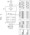
- the result of the control of the controller 100 as described above may be the same as shown in FIG. 5 .
- the input current before being compensated with the compensation value and the voltage of the smoothing unit 20 has a waveform pulsated due to the harmonic component.
- the output of the inverter unit 30 is adjusted to reduce harmonics of the input current, whereby the input current and the voltage of the smoothing unit 20 has a pulsation-reduced waveform.
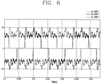
- the input current with reduced harmonics after the controller 40 adjusts the output of the inverter unit 30 based on a result of detecting the voltage of the smoothing unit 20 and the output current of the inverter unit 30 may have a waveform reduced in a portion corresponding to the harmonics from the waveform of the input current before the harmonics is reduced as illustrated in FIG. 6 .
- the waveform may have a reduced pulsation as part corresponding to harmonics is reduced from the waveform of the input current before the harmonics is reduced.
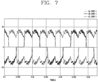
- the input current with the reduced harmonics may be detected as a waveform in which maximum and minimum peak values are reduced to below a preset reference value, from the waveform of the input current before the harmonics is reduced as illustrated in FIG. 7 .
- the input current reduced in harmonics may be detected as a waveform in which the maximum and minimum peak values are reduced to below the preset reference value, from the waveform of the input current before the harmonics detected on the basis of the same detection reference is reduced.
- FIGS. 6 and 7 illustrate waveforms of the input currents before and after the harmonics is reduced, and the waveforms of the input currents may be detected to have waveforms different from those illustrated in FIGS. 6 and 7 .
- control method the method for controlling a motor control device (hereinafter, referred to as a "control method") disclosed in this disclosure will be described, and here, the parts overlapping with those described above in the motor control device will be omitted as much as possible and an embodiment of the control method will be mainly described.
- the control method may be a control method of a motor control device.
- the control method may be a method for controlling a control device for controlling a motor.
- control method may be a control method for controlling a motor.
- the control method may be a control method of a control means included in the motor control device and controlling the motor control device.
- the control method may be a control method of a motor control device without an LC filter.
- the control method may be a control method for reducing harmonics of an input current of a motor control device without a reactor of an LC filter.
- the control method may be a control method for controlling the control device 100 described above.
- the control method may be a control method of the controller 40 included in the control device 100 described above.
- the control method may be a method for reducing harmonics of an input current of the controller 40 included in the control device 100 described above.
- the control method may be a control method of a motor control device including an input unit rectifying AC power input from the outside to DC power, a smoothing unit smoothing the rectified DC power, and an inverter unit converting the smoothed DC power into AC power and outputting the AC power to the motor.
- the control method includes detecting a voltage of the smoothing unit and an output current of the inverter unit (S100), calculating a compensation value for compensating for a harmonic component in an output of the inverter unit on the basis of the voltage of the smoothing unit and the output current (S200), and adjusting an output of the inverter unit by controlling a switching operation of the inverter unit such that the compensation value is reflected in the output of the inverter (S300).
- the control device may include a reactor forming an LC filter, but hereinafter, an embodiment of the control method will be described on the premise that the control device does not have the reactor.
- the smoothing unit may be a film capacitor.
- the smoothing unit may be a DC link capacitor formed as a small film capacitor having a small capacity.
- the detecting step (S100) may include detecting a voltage of the smoothing unit (S110) and detecting an output current of the inverter unit (S120).
- the detecting step (S100) may further include detecting an input voltage input to the input unit (S130).
- a voltage of the smoothing unit, an output current of the inverter unit, and an input voltage input to the input unit may be detected.
- the step (S110) of detecting a voltage of the smoothing unit, the step (S120) of detecting an output current of the inverter unit, and the step (S130) of detecting an input voltage input to the input unit may be performed in order changed in each step, regardless of order, or simultaneously.
- the calculating step (S200) may include extracting a harmonic component from a voltage of the smoothing unit and determining a waveform of the compensation value according to the harmonic component (S210), calculating an output magnitude of the inverter unit on the basis of the output current to determine a magnitude of the compensation value according to the output magnitude (S220), and calculating the compensation value according to a determination result (S240).
- the calculating step (S200) may further include detecting a phase of the input voltage and determining a phase of the compensation value according to the phase of the input voltage (S230).
- the compensation value may be calculated by determining a waveform of the compensation value, a magnitude of the compensation value, and a phase of the compensation value.
- the step (S210) of determining a waveform of the compensation value may be performed in order changed in each step, regardless of order, or simultaneously.
- harmonics of the input current input to the input unit is reduced, and the input current with reduced harmonics may be detected to have a waveform in which maximum and minimum peak values are reduced to below a preset reference value, from a waveform of the input current before the harmonics is reduced.
- the control method may be a method for controlling the motor control device 100 including the input unit 10 rectifying AC power input from the outside to DC power, a smoothing unit 20 smoothing the rectified DC power, and an inverter unit 30 converting the smoothed DC power into AC power and outputting the AC power to the motor 200.
- the detecting step (S100), the calculating step (S200), and the adjusting step (S300) may be performed in the controller 40 controlling a switching operation of the inverter unit 30.
Landscapes
- Engineering & Computer Science (AREA)
- Power Engineering (AREA)
- Microelectronics & Electronic Packaging (AREA)
- Manufacturing & Machinery (AREA)
- Physics & Mathematics (AREA)
- General Physics & Mathematics (AREA)
- Control Of Ac Motors In General (AREA)
- Inverter Devices (AREA)
Claims (7)
- Dispositif de commande de moteur comprenant :une unité d'entrée (10) destinée à redresser une entrée de puissance en courant alternatif provenant de l'extérieur, en une puissance en courant continu ;une unité de lissage (20) destinée à lisser la puissance en courant continu, dans laquelle l'unité de lissage (20) est un condensateur à film ;une unité d'onduleur (30) destinée à convertir la puissance en courant continu lissée, en une puissance en courant alternatif, et à fournir en sortie la puissance en courant alternatif convertie à un moteur (200) ; etun contrôleur (40) destiné à commander une opération de commutation de l'unité d'onduleur (30) ;dans lequel le dispositif de commande de moteur est un dispositif sans composante réactive à courant continu ; etdans lequel le contrôleur (40) est configuré de manière à ajuster une sortie de l'unité d'onduleur (30) en commandant une opération de commutation de l'unité d'onduleur (30) sur la base d'un résultat de détection d'une tension de l'unité de lissage (20) et d'un courant de sortie de l'unité d'onduleur (30), à calculer une valeur de compensation pour compenser une composante harmonique dans une sortie de l'unité d'onduleur (30), sur la base de la tension de l'unité de lissage (20) et du courant de sortie, et à réduire une harmonique d'un courant d'entrée appliqué en entrée à l'unité d'entrée (10) ;dans lequel le contrôleur (40) est configuré de manière à extraire une composante harmonique de la tension de l'unité de lissage (20), à déterminer une forme d'onde de la valeur de compensation, de sorte que la forme d'onde de la valeur de compensation correspond à la composante harmonique, à calculer une grandeur de sortie de l'unité d'onduleur (30) sur la base du courant de sortie, la grandeur de sortie étant une grandeur de la puissance de sortie fournie au moteur (200), à déterminer une grandeur de la valeur de compensation, de sorte que la grandeur de la valeur de compensation correspond à la grandeur de sortie, et à ajuster une sortie de l'unité d'onduleur (30), sur la base de la composante harmonique et de la grandeur de sortie ;dans lequel le dispositif de commande de moteur est configuré de manière à détecter le courant d'entrée avec une harmonique réduite, en tant qu'une forme d'onde dans laquelle les valeurs de crête maximale et minimale sont réduites en dessous d'une valeur de référence prédéfinie, à partir d'une forme d'onde du courant d'entrée avant que l'harmonique ne soit réduite ; etdans lequel le contrôleur (40) est configuré de manière à commander l'opération de commutation de l'unité d'onduleur (30) de sorte que la valeur de compensation est reflétée dans la sortie de l'unité d'onduleur (30), et à ajuster une sortie de l'unité d'onduleur (30) selon la valeur de compensation.
- Dispositif de commande de moteur selon la revendication 1, dans lequel :
le contrôleur (40) est configuré de manière à calculer la valeur de compensation en déterminant une forme d'onde de la valeur de compensation selon la composante harmonique, et à déterminer une grandeur de la valeur de compensation selon la grandeur de sortie. - Dispositif de commande de moteur selon l'une quelconque des revendications 1 et 2, dans lequel :
le contrôleur (40) est configuré de manière à détecter une tension d'entrée appliquée en entrée à l'unité d'entrée (10), à détecter une phase de la tension d'entrée, et à déterminer une phase de la valeur de compensation selon la phase de la tension d'entrée. - Procédé de commande d'un dispositif de commande de moteur incluant une unité d'entrée (10) recevant une puissance en courant alternatif en provenance de l'extérieur, une unité de redressement redressant la puissance en courant alternatif d'entrée en une puissance en courant continu, une unité de lissage (20) lissant la puissance en courant continu, dans laquelle l'unité de lissage (20) est un condensateur à film, et une unité d'onduleur (30) convertissant la puissance en courant continu lissée en une puissance en courant alternatif, et fournissant en sortie la puissance en courant alternatif convertie à un moteur (200), le procédé comprenant les étapes ci-dessous consistant à :détecter une tension de l'unité de lissage (20) et un courant de sortie de l'unité d'onduleur (30) ;calculer une valeur de compensation pour compenser une composante harmonique dans une sortie de l'unité d'onduleur (30) sur la base de la tension de l'unité de lissage (20) et du courant de sortie ; etajuster une sortie de l'unité d'onduleur (30) en commandant une opération de commutation de l'unité d'onduleur (30), de sorte que la valeur de compensation est reflétée dans la sortie de l'unité d'onduleur (30) ;dans lequel le dispositif de commande de moteur est un dispositif sans composante réactive à courant continu ; etdans lequel l'étape de calcul inclut les étapes ci-dessous consistant à :extraire une composante harmonique de la tension de l'unité de lissage (20) et déterminer une forme d'onde de la valeur de compensation selon la composante harmonique, de sorte que la forme d'onde de la valeur de compensation correspond à la composante harmonique ;calculer une grandeur de sortie de l'unité d'onduleur (30) sur la base du courant de sortie, la grandeur de sortie étant une grandeur de la puissance de sortie fournie au moteur (200), et déterminer une grandeur de la valeur de compensation selon la grandeur de sortie, de sorte que la grandeur de la valeur de compensation correspond à la grandeur de sortie ; etcalculer la valeur de compensation selon un résultat de détermination ; etdans lequel, à l'étape d'ajustement, l'harmonique du courant d'entrée appliqué en entrée à l'unité d'entrée (10) est réduite ; etdans lequel le courant d'entrée avec une harmonique réduite est détecté en tant qu'une forme d'onde dans laquelle des valeurs de crête maximale et minimale sont réduites en dessous d'une valeur de référence prédéfinie, à partir d'une forme d'onde du courant d'entrée avant que l'harmonique ne soit réduite.
- Procédé selon la revendication 4, dans lequel :
l'étape de détection est mise en œuvre dans l'ordre suivant :détecter une tension de l'unité de lissage (20) ; etdétecter un courant de sortie de l'unité d'onduleur (30). - Procédé selon l'une quelconque des revendications 4 et 5, dans lequel :
l'étape de détection inclut l'étape consistant à détecter une tension d'entrée appliquée en entrée à l'unité d'entrée (10). - Procédé selon la revendication 4, dans lequel :
l'étape de calcul inclut les étapes ci-après consistant à : détecter une phase de la tension d'entrée et déterminer une phase de la valeur de compensation selon la phase de la tension d'entrée.
Applications Claiming Priority (1)
| Application Number | Priority Date | Filing Date | Title |
|---|---|---|---|
| KR1020170000411A KR101888842B1 (ko) | 2017-01-02 | 2017-01-02 | 모터 제어 장치 및 모터 제어 장치의 제어 방법 |
Publications (2)
| Publication Number | Publication Date |
|---|---|
| EP3343742A1 EP3343742A1 (fr) | 2018-07-04 |
| EP3343742B1 true EP3343742B1 (fr) | 2022-02-02 |
Family
ID=60813739
Family Applications (1)
| Application Number | Title | Priority Date | Filing Date |
|---|---|---|---|
| EP17210866.4A Active EP3343742B1 (fr) | 2017-01-02 | 2017-12-28 | Dispositif de commande de moteur et procédé pour commander un dispositif de commande de moteur |
Country Status (5)
| Country | Link |
|---|---|
| US (1) | US10644632B2 (fr) |
| EP (1) | EP3343742B1 (fr) |
| KR (1) | KR101888842B1 (fr) |
| CN (1) | CN110140293B (fr) |
| WO (1) | WO2018124467A1 (fr) |
Families Citing this family (4)
| Publication number | Priority date | Publication date | Assignee | Title |
|---|---|---|---|---|
| CN113261194B (zh) * | 2019-01-04 | 2025-04-08 | 茵梦达有限责任公司 | 减少电源中的输入谐波失真 |
| CN110350775A (zh) * | 2019-07-17 | 2019-10-18 | 珠海格力电器股份有限公司 | 一种谐波处理电路、压缩机控制电路和空调机组 |
| EP3799282A1 (fr) | 2019-09-27 | 2021-03-31 | Siemens Aktiengesellschaft | Convertisseur de courant à amortissement actif de la tension d'un circuit intermédiaire |
| JPWO2023095311A1 (fr) * | 2021-11-26 | 2023-06-01 |
Citations (1)
| Publication number | Priority date | Publication date | Assignee | Title |
|---|---|---|---|---|
| US20130300327A1 (en) * | 2011-01-18 | 2013-11-14 | Daikin Industries, Ltd. | Power conversion apparatus |
Family Cites Families (18)
| Publication number | Priority date | Publication date | Assignee | Title |
|---|---|---|---|---|
| EP0165020B1 (fr) * | 1984-06-11 | 1989-10-11 | Kabushiki Kaisha Toshiba | Convertisseur de puissance pour une charge à courant alternatif |
| EP0588213B1 (fr) * | 1992-09-16 | 1996-12-18 | Hitachi, Ltd. | Méthode de mesure des constantes charactéristiques pour moteur à courant alternatif et contrÔleur à base de cette méthode |
| JP4357967B2 (ja) * | 2002-03-22 | 2009-11-04 | パナソニック株式会社 | シンクロナスリラクタンスモータの制御装置 |
| JP4760001B2 (ja) | 2004-12-09 | 2011-08-31 | ダイキン工業株式会社 | 多相電流供給回路、駆動装置、圧縮機、及び空気調和機 |
| KR100823922B1 (ko) * | 2006-03-14 | 2008-04-22 | 엘지전자 주식회사 | 직류 전원 공급 장치 및 그 방법 |
| CN101467344B (zh) * | 2006-04-24 | 2012-05-23 | 松下电器产业株式会社 | 逆变器装置及空调机 |
| JP4389906B2 (ja) * | 2006-06-29 | 2009-12-24 | パナソニック株式会社 | 交流電源直結型ブラシレスdcモータおよびそれを搭載した電気機器 |
| WO2008026270A1 (fr) * | 2006-08-31 | 2008-03-06 | Mitsubishi Electric Corporation | Dispositif de commande de moteur électrique, et dispositif de commande de compresseur |
| KR101228451B1 (ko) * | 2006-09-12 | 2013-02-01 | 엘지전자 주식회사 | 공조기의 직류전원 공급 장치 및 방법 |
| JP4500857B2 (ja) * | 2008-02-28 | 2010-07-14 | 株式会社日立製作所 | 電源回路及び、それを用いたモータ駆動装置,空調機 |
| KR101655799B1 (ko) * | 2010-01-05 | 2016-09-08 | 엘지전자 주식회사 | 공기조화기의 전동기 구동장치 |
| GB201006386D0 (en) | 2010-04-16 | 2010-06-02 | Dyson Technology Ltd | Control of a brushless motor |
| JP2012090460A (ja) * | 2010-10-21 | 2012-05-10 | Sharp Corp | モータ制御装置 |
| KR101216464B1 (ko) * | 2010-12-14 | 2012-12-31 | 엘지전자 주식회사 | 모터 제어 장치 및 이의 제어 방법 |
| US9257931B2 (en) * | 2011-01-18 | 2016-02-09 | Daikin Industries, Ltd. | Power conversion apparatus |
| US9287815B2 (en) * | 2011-09-30 | 2016-03-15 | Daikin Industries, Ltd. | Power converter |
| JP5928216B2 (ja) * | 2012-07-19 | 2016-06-01 | ダイキン工業株式会社 | インバータ制御装置 |
| JP2015104178A (ja) * | 2013-11-22 | 2015-06-04 | 日本電産テクノモータ株式会社 | モータ駆動装置 |
-
2017
- 2017-01-02 KR KR1020170000411A patent/KR101888842B1/ko not_active Expired - Fee Related
- 2017-11-15 WO PCT/KR2017/012928 patent/WO2018124467A1/fr not_active Ceased
- 2017-11-15 CN CN201780081822.9A patent/CN110140293B/zh active Active
- 2017-12-28 EP EP17210866.4A patent/EP3343742B1/fr active Active
- 2017-12-29 US US15/858,777 patent/US10644632B2/en active Active
Patent Citations (1)
| Publication number | Priority date | Publication date | Assignee | Title |
|---|---|---|---|---|
| US20130300327A1 (en) * | 2011-01-18 | 2013-11-14 | Daikin Industries, Ltd. | Power conversion apparatus |
Also Published As
| Publication number | Publication date |
|---|---|
| EP3343742A1 (fr) | 2018-07-04 |
| KR20180079794A (ko) | 2018-07-11 |
| CN110140293A (zh) | 2019-08-16 |
| US10644632B2 (en) | 2020-05-05 |
| WO2018124467A1 (fr) | 2018-07-05 |
| US20180191286A1 (en) | 2018-07-05 |
| CN110140293B (zh) | 2023-05-30 |
| KR101888842B1 (ko) | 2018-08-16 |
Similar Documents
| Publication | Publication Date | Title |
|---|---|---|
| US9257931B2 (en) | Power conversion apparatus | |
| EP3236575B9 (fr) | Méthode de contrôle d'un circuit de charge et de décharge et convertisseur direct de puissance | |
| US11218107B2 (en) | Control device for power converter | |
| KR102000060B1 (ko) | 전류 센서의 옵셋 보정 장치 | |
| EP3343742A1 (fr) | Dispositif de commande de moteur et procédé pour commander un dispositif de commande de moteur | |
| KR20140002736A (ko) | 전력 변환 장치 | |
| JP5205420B2 (ja) | 電動機システム,電力変換装置および電力変換装置の制御方法 | |
| EP2763309B1 (fr) | Appareil onduleur et procédé de contrôle de l'appareil onduleur | |
| JPWO2008026270A1 (ja) | 電動機駆動装置及び圧縮機駆動装置 | |
| US10651768B2 (en) | Motor control device and method for controlling motor control device | |
| EP2273661A1 (fr) | Procédé de commande de convertisseur | |
| JP5888074B2 (ja) | 電力変換装置 | |
| JP4572595B2 (ja) | コンバータ制御方法及びコンバータ制御装置並びに空調機及びその制御方法及び制御装置 | |
| US9231514B2 (en) | Motor control apparatus and motor control method | |
| JP2009278789A (ja) | モータ駆動用インバータ制御装置 | |
| KR101096148B1 (ko) | Hvdc 제어기 및 이를 포함하는 hvdc 시스템 | |
| JP2020014326A (ja) | 電力変換装置 | |
| JP5793005B2 (ja) | 電力変換装置及びその制御装置 | |
| KR101911267B1 (ko) | 전력 변환 장치 및 이를 포함하는 공기 조화기 | |
| JP2002315355A (ja) | 電力変換装置 | |
| JP2005124298A (ja) | インダクションモータ駆動用インバータ制御装置および空気調和機 | |
| US20220200505A1 (en) | Power conversion device and method for controlling same | |
| JP2015037360A (ja) | 電力変換装置及び電動機駆動装置 | |
| KR20190029091A (ko) | 배터리 충전 장치 | |
| HK1119843A1 (en) | Power converter |
Legal Events
| Date | Code | Title | Description |
|---|---|---|---|
| PUAI | Public reference made under article 153(3) epc to a published international application that has entered the european phase |
Free format text: ORIGINAL CODE: 0009012 |
|
| STAA | Information on the status of an ep patent application or granted ep patent |
Free format text: STATUS: REQUEST FOR EXAMINATION WAS MADE |
|
| 17P | Request for examination filed |
Effective date: 20180129 |
|
| AK | Designated contracting states |
Kind code of ref document: A1 Designated state(s): AL AT BE BG CH CY CZ DE DK EE ES FI FR GB GR HR HU IE IS IT LI LT LU LV MC MK MT NL NO PL PT RO RS SE SI SK SM TR |
|
| AX | Request for extension of the european patent |
Extension state: BA ME |
|
| RBV | Designated contracting states (corrected) |
Designated state(s): AL AT BE BG CH CY CZ DE DK EE ES FI FR GB GR HR HU IE IS IT LI LT LU LV MC MK MT NL NO PL PT RO RS SE SI SK SM TR |
|
| STAA | Information on the status of an ep patent application or granted ep patent |
Free format text: STATUS: EXAMINATION IS IN PROGRESS |
|
| 17Q | First examination report despatched |
Effective date: 20190425 |
|
| GRAP | Despatch of communication of intention to grant a patent |
Free format text: ORIGINAL CODE: EPIDOSNIGR1 |
|
| STAA | Information on the status of an ep patent application or granted ep patent |
Free format text: STATUS: GRANT OF PATENT IS INTENDED |
|
| INTG | Intention to grant announced |
Effective date: 20210719 |
|
| GRAS | Grant fee paid |
Free format text: ORIGINAL CODE: EPIDOSNIGR3 |
|
| GRAA | (expected) grant |
Free format text: ORIGINAL CODE: 0009210 |
|
| STAA | Information on the status of an ep patent application or granted ep patent |
Free format text: STATUS: THE PATENT HAS BEEN GRANTED |
|
| AK | Designated contracting states |
Kind code of ref document: B1 Designated state(s): AL AT BE BG CH CY CZ DE DK EE ES FI FR GB GR HR HU IE IS IT LI LT LU LV MC MK MT NL NO PL PT RO RS SE SI SK SM TR |
|
| REG | Reference to a national code |
Ref country code: GB Ref legal event code: FG4D |
|
| REG | Reference to a national code |
Ref country code: CH Ref legal event code: EP Ref country code: AT Ref legal event code: REF Ref document number: 1466834 Country of ref document: AT Kind code of ref document: T Effective date: 20220215 |
|
| REG | Reference to a national code |
Ref country code: DE Ref legal event code: R096 Ref document number: 602017052998 Country of ref document: DE |
|
| REG | Reference to a national code |
Ref country code: IE Ref legal event code: FG4D |
|
| REG | Reference to a national code |
Ref country code: LT Ref legal event code: MG9D |
|
| REG | Reference to a national code |
Ref country code: NL Ref legal event code: MP Effective date: 20220202 |
|
| REG | Reference to a national code |
Ref country code: AT Ref legal event code: MK05 Ref document number: 1466834 Country of ref document: AT Kind code of ref document: T Effective date: 20220202 |
|
| PG25 | Lapsed in a contracting state [announced via postgrant information from national office to epo] |
Ref country code: SE Free format text: LAPSE BECAUSE OF FAILURE TO SUBMIT A TRANSLATION OF THE DESCRIPTION OR TO PAY THE FEE WITHIN THE PRESCRIBED TIME-LIMIT Effective date: 20220202 Ref country code: RS Free format text: LAPSE BECAUSE OF FAILURE TO SUBMIT A TRANSLATION OF THE DESCRIPTION OR TO PAY THE FEE WITHIN THE PRESCRIBED TIME-LIMIT Effective date: 20220202 Ref country code: PT Free format text: LAPSE BECAUSE OF FAILURE TO SUBMIT A TRANSLATION OF THE DESCRIPTION OR TO PAY THE FEE WITHIN THE PRESCRIBED TIME-LIMIT Effective date: 20220602 Ref country code: NO Free format text: LAPSE BECAUSE OF FAILURE TO SUBMIT A TRANSLATION OF THE DESCRIPTION OR TO PAY THE FEE WITHIN THE PRESCRIBED TIME-LIMIT Effective date: 20220502 Ref country code: NL Free format text: LAPSE BECAUSE OF FAILURE TO SUBMIT A TRANSLATION OF THE DESCRIPTION OR TO PAY THE FEE WITHIN THE PRESCRIBED TIME-LIMIT Effective date: 20220202 Ref country code: LT Free format text: LAPSE BECAUSE OF FAILURE TO SUBMIT A TRANSLATION OF THE DESCRIPTION OR TO PAY THE FEE WITHIN THE PRESCRIBED TIME-LIMIT Effective date: 20220202 Ref country code: HR Free format text: LAPSE BECAUSE OF FAILURE TO SUBMIT A TRANSLATION OF THE DESCRIPTION OR TO PAY THE FEE WITHIN THE PRESCRIBED TIME-LIMIT Effective date: 20220202 Ref country code: ES Free format text: LAPSE BECAUSE OF FAILURE TO SUBMIT A TRANSLATION OF THE DESCRIPTION OR TO PAY THE FEE WITHIN THE PRESCRIBED TIME-LIMIT Effective date: 20220202 Ref country code: BG Free format text: LAPSE BECAUSE OF FAILURE TO SUBMIT A TRANSLATION OF THE DESCRIPTION OR TO PAY THE FEE WITHIN THE PRESCRIBED TIME-LIMIT Effective date: 20220502 |
|
| PG25 | Lapsed in a contracting state [announced via postgrant information from national office to epo] |
Ref country code: PL Free format text: LAPSE BECAUSE OF FAILURE TO SUBMIT A TRANSLATION OF THE DESCRIPTION OR TO PAY THE FEE WITHIN THE PRESCRIBED TIME-LIMIT Effective date: 20220202 Ref country code: LV Free format text: LAPSE BECAUSE OF FAILURE TO SUBMIT A TRANSLATION OF THE DESCRIPTION OR TO PAY THE FEE WITHIN THE PRESCRIBED TIME-LIMIT Effective date: 20220202 Ref country code: GR Free format text: LAPSE BECAUSE OF FAILURE TO SUBMIT A TRANSLATION OF THE DESCRIPTION OR TO PAY THE FEE WITHIN THE PRESCRIBED TIME-LIMIT Effective date: 20220503 Ref country code: FI Free format text: LAPSE BECAUSE OF FAILURE TO SUBMIT A TRANSLATION OF THE DESCRIPTION OR TO PAY THE FEE WITHIN THE PRESCRIBED TIME-LIMIT Effective date: 20220202 Ref country code: AT Free format text: LAPSE BECAUSE OF FAILURE TO SUBMIT A TRANSLATION OF THE DESCRIPTION OR TO PAY THE FEE WITHIN THE PRESCRIBED TIME-LIMIT Effective date: 20220202 |
|
| PG25 | Lapsed in a contracting state [announced via postgrant information from national office to epo] |
Ref country code: IS Free format text: LAPSE BECAUSE OF FAILURE TO SUBMIT A TRANSLATION OF THE DESCRIPTION OR TO PAY THE FEE WITHIN THE PRESCRIBED TIME-LIMIT Effective date: 20220602 |
|
| PG25 | Lapsed in a contracting state [announced via postgrant information from national office to epo] |
Ref country code: SM Free format text: LAPSE BECAUSE OF FAILURE TO SUBMIT A TRANSLATION OF THE DESCRIPTION OR TO PAY THE FEE WITHIN THE PRESCRIBED TIME-LIMIT Effective date: 20220202 Ref country code: SK Free format text: LAPSE BECAUSE OF FAILURE TO SUBMIT A TRANSLATION OF THE DESCRIPTION OR TO PAY THE FEE WITHIN THE PRESCRIBED TIME-LIMIT Effective date: 20220202 Ref country code: RO Free format text: LAPSE BECAUSE OF FAILURE TO SUBMIT A TRANSLATION OF THE DESCRIPTION OR TO PAY THE FEE WITHIN THE PRESCRIBED TIME-LIMIT Effective date: 20220202 Ref country code: EE Free format text: LAPSE BECAUSE OF FAILURE TO SUBMIT A TRANSLATION OF THE DESCRIPTION OR TO PAY THE FEE WITHIN THE PRESCRIBED TIME-LIMIT Effective date: 20220202 Ref country code: DK Free format text: LAPSE BECAUSE OF FAILURE TO SUBMIT A TRANSLATION OF THE DESCRIPTION OR TO PAY THE FEE WITHIN THE PRESCRIBED TIME-LIMIT Effective date: 20220202 Ref country code: CZ Free format text: LAPSE BECAUSE OF FAILURE TO SUBMIT A TRANSLATION OF THE DESCRIPTION OR TO PAY THE FEE WITHIN THE PRESCRIBED TIME-LIMIT Effective date: 20220202 |
|
| REG | Reference to a national code |
Ref country code: DE Ref legal event code: R097 Ref document number: 602017052998 Country of ref document: DE |
|
| PG25 | Lapsed in a contracting state [announced via postgrant information from national office to epo] |
Ref country code: AL Free format text: LAPSE BECAUSE OF FAILURE TO SUBMIT A TRANSLATION OF THE DESCRIPTION OR TO PAY THE FEE WITHIN THE PRESCRIBED TIME-LIMIT Effective date: 20220202 |
|
| PLBE | No opposition filed within time limit |
Free format text: ORIGINAL CODE: 0009261 |
|
| STAA | Information on the status of an ep patent application or granted ep patent |
Free format text: STATUS: NO OPPOSITION FILED WITHIN TIME LIMIT |
|
| 26N | No opposition filed |
Effective date: 20221103 |
|
| PG25 | Lapsed in a contracting state [announced via postgrant information from national office to epo] |
Ref country code: SI Free format text: LAPSE BECAUSE OF FAILURE TO SUBMIT A TRANSLATION OF THE DESCRIPTION OR TO PAY THE FEE WITHIN THE PRESCRIBED TIME-LIMIT Effective date: 20220202 |
|
| PG25 | Lapsed in a contracting state [announced via postgrant information from national office to epo] |
Ref country code: IT Free format text: LAPSE BECAUSE OF FAILURE TO SUBMIT A TRANSLATION OF THE DESCRIPTION OR TO PAY THE FEE WITHIN THE PRESCRIBED TIME-LIMIT Effective date: 20220202 |
|
| REG | Reference to a national code |
Ref country code: CH Ref legal event code: PL |
|
| GBPC | Gb: european patent ceased through non-payment of renewal fee |
Effective date: 20221228 |
|
| REG | Reference to a national code |
Ref country code: BE Ref legal event code: MM Effective date: 20221231 |
|
| PG25 | Lapsed in a contracting state [announced via postgrant information from national office to epo] |
Ref country code: LU Free format text: LAPSE BECAUSE OF NON-PAYMENT OF DUE FEES Effective date: 20221228 |
|
| PG25 | Lapsed in a contracting state [announced via postgrant information from national office to epo] |
Ref country code: LI Free format text: LAPSE BECAUSE OF NON-PAYMENT OF DUE FEES Effective date: 20221231 Ref country code: IE Free format text: LAPSE BECAUSE OF NON-PAYMENT OF DUE FEES Effective date: 20221228 Ref country code: GB Free format text: LAPSE BECAUSE OF NON-PAYMENT OF DUE FEES Effective date: 20221228 Ref country code: CH Free format text: LAPSE BECAUSE OF NON-PAYMENT OF DUE FEES Effective date: 20221231 |
|
| PG25 | Lapsed in a contracting state [announced via postgrant information from national office to epo] |
Ref country code: FR Free format text: LAPSE BECAUSE OF NON-PAYMENT OF DUE FEES Effective date: 20221231 Ref country code: BE Free format text: LAPSE BECAUSE OF NON-PAYMENT OF DUE FEES Effective date: 20221231 |
|
| PG25 | Lapsed in a contracting state [announced via postgrant information from national office to epo] |
Ref country code: HU Free format text: LAPSE BECAUSE OF FAILURE TO SUBMIT A TRANSLATION OF THE DESCRIPTION OR TO PAY THE FEE WITHIN THE PRESCRIBED TIME-LIMIT; INVALID AB INITIO Effective date: 20171228 |
|
| PG25 | Lapsed in a contracting state [announced via postgrant information from national office to epo] |
Ref country code: CY Free format text: LAPSE BECAUSE OF FAILURE TO SUBMIT A TRANSLATION OF THE DESCRIPTION OR TO PAY THE FEE WITHIN THE PRESCRIBED TIME-LIMIT Effective date: 20220202 |
|
| PG25 | Lapsed in a contracting state [announced via postgrant information from national office to epo] |
Ref country code: MK Free format text: LAPSE BECAUSE OF FAILURE TO SUBMIT A TRANSLATION OF THE DESCRIPTION OR TO PAY THE FEE WITHIN THE PRESCRIBED TIME-LIMIT Effective date: 20220202 |
|
| PG25 | Lapsed in a contracting state [announced via postgrant information from national office to epo] |
Ref country code: MC Free format text: LAPSE BECAUSE OF FAILURE TO SUBMIT A TRANSLATION OF THE DESCRIPTION OR TO PAY THE FEE WITHIN THE PRESCRIBED TIME-LIMIT Effective date: 20220202 |
|
| PG25 | Lapsed in a contracting state [announced via postgrant information from national office to epo] |
Ref country code: MC Free format text: LAPSE BECAUSE OF FAILURE TO SUBMIT A TRANSLATION OF THE DESCRIPTION OR TO PAY THE FEE WITHIN THE PRESCRIBED TIME-LIMIT Effective date: 20220202 |
|
| PG25 | Lapsed in a contracting state [announced via postgrant information from national office to epo] |
Ref country code: MT Free format text: LAPSE BECAUSE OF FAILURE TO SUBMIT A TRANSLATION OF THE DESCRIPTION OR TO PAY THE FEE WITHIN THE PRESCRIBED TIME-LIMIT Effective date: 20220202 |
|
| PG25 | Lapsed in a contracting state [announced via postgrant information from national office to epo] |
Ref country code: TR Free format text: LAPSE BECAUSE OF FAILURE TO SUBMIT A TRANSLATION OF THE DESCRIPTION OR TO PAY THE FEE WITHIN THE PRESCRIBED TIME-LIMIT Effective date: 20220202 |
|
| PGFP | Annual fee paid to national office [announced via postgrant information from national office to epo] |
Ref country code: DE Payment date: 20251105 Year of fee payment: 9 |