EP3343751B1 - Kühlschrank - Google Patents
Kühlschrank Download PDFInfo
- Publication number
- EP3343751B1 EP3343751B1 EP16841065.2A EP16841065A EP3343751B1 EP 3343751 B1 EP3343751 B1 EP 3343751B1 EP 16841065 A EP16841065 A EP 16841065A EP 3343751 B1 EP3343751 B1 EP 3343751B1
- Authority
- EP
- European Patent Office
- Prior art keywords
- motor
- compressor
- brushless
- speed
- driving device
- Prior art date
- Legal status (The legal status is an assumption and is not a legal conclusion. Google has not performed a legal analysis and makes no representation as to the accuracy of the status listed.)
- Active
Links
Images


Classifications
-
- H—ELECTRICITY
- H02—GENERATION; CONVERSION OR DISTRIBUTION OF ELECTRIC POWER
- H02P—CONTROL OR REGULATION OF ELECTRIC MOTORS, ELECTRIC GENERATORS OR DYNAMO-ELECTRIC CONVERTERS; CONTROLLING TRANSFORMERS, REACTORS OR CHOKE COILS
- H02P6/00—Arrangements for controlling synchronous motors or other dynamo-electric motors using electronic commutation dependent on the rotor position; Electronic commutators therefor
- H02P6/14—Electronic commutators
- H02P6/16—Circuit arrangements for detecting position
- H02P6/18—Circuit arrangements for detecting position without separate position detecting elements
- H02P6/182—Circuit arrangements for detecting position without separate position detecting elements using back-emf in windings
-
- F—MECHANICAL ENGINEERING; LIGHTING; HEATING; WEAPONS; BLASTING
- F25—REFRIGERATION OR COOLING; COMBINED HEATING AND REFRIGERATION SYSTEMS; HEAT PUMP SYSTEMS; MANUFACTURE OR STORAGE OF ICE; LIQUEFACTION SOLIDIFICATION OF GASES
- F25B—REFRIGERATION MACHINES, PLANTS OR SYSTEMS; COMBINED HEATING AND REFRIGERATION SYSTEMS; HEAT PUMP SYSTEMS
- F25B49/00—Arrangement or mounting of control or safety devices
- F25B49/02—Arrangement or mounting of control or safety devices for compression type machines, plants or systems
-
- H—ELECTRICITY
- H02—GENERATION; CONVERSION OR DISTRIBUTION OF ELECTRIC POWER
- H02M—APPARATUS FOR CONVERSION BETWEEN AC AND AC, BETWEEN AC AND DC, OR BETWEEN DC AND DC, AND FOR USE WITH MAINS OR SIMILAR POWER SUPPLY SYSTEMS; CONVERSION OF DC OR AC INPUT POWER INTO SURGE OUTPUT POWER; CONTROL OR REGULATION THEREOF
- H02M7/00—Conversion of AC power input into DC power output; Conversion of DC power input into AC power output
- H02M7/42—Conversion of DC power input into AC power output without possibility of reversal
- H02M7/44—Conversion of DC power input into AC power output without possibility of reversal by static converters
- H02M7/48—Conversion of DC power input into AC power output without possibility of reversal by static converters using discharge tubes with control electrode or semiconductor devices with control electrode
- H02M7/53—Conversion of DC power input into AC power output without possibility of reversal by static converters using discharge tubes with control electrode or semiconductor devices with control electrode using devices of a triode or transistor type requiring continuous application of a control signal
- H02M7/537—Conversion of DC power input into AC power output without possibility of reversal by static converters using discharge tubes with control electrode or semiconductor devices with control electrode using devices of a triode or transistor type requiring continuous application of a control signal using semiconductor devices only, e.g. single switched pulse inverters
- H02M7/5387—Conversion of DC power input into AC power output without possibility of reversal by static converters using discharge tubes with control electrode or semiconductor devices with control electrode using devices of a triode or transistor type requiring continuous application of a control signal using semiconductor devices only, e.g. single switched pulse inverters in a bridge configuration
- H02M7/53871—Conversion of DC power input into AC power output without possibility of reversal by static converters using discharge tubes with control electrode or semiconductor devices with control electrode using devices of a triode or transistor type requiring continuous application of a control signal using semiconductor devices only, e.g. single switched pulse inverters in a bridge configuration with automatic control of output voltage or current
-
- H—ELECTRICITY
- H02—GENERATION; CONVERSION OR DISTRIBUTION OF ELECTRIC POWER
- H02P—CONTROL OR REGULATION OF ELECTRIC MOTORS, ELECTRIC GENERATORS OR DYNAMO-ELECTRIC CONVERTERS; CONTROLLING TRANSFORMERS, REACTORS OR CHOKE COILS
- H02P6/00—Arrangements for controlling synchronous motors or other dynamo-electric motors using electronic commutation dependent on the rotor position; Electronic commutators therefor
- H02P6/20—Arrangements for starting
-
- F—MECHANICAL ENGINEERING; LIGHTING; HEATING; WEAPONS; BLASTING
- F25—REFRIGERATION OR COOLING; COMBINED HEATING AND REFRIGERATION SYSTEMS; HEAT PUMP SYSTEMS; MANUFACTURE OR STORAGE OF ICE; LIQUEFACTION SOLIDIFICATION OF GASES
- F25B—REFRIGERATION MACHINES, PLANTS OR SYSTEMS; COMBINED HEATING AND REFRIGERATION SYSTEMS; HEAT PUMP SYSTEMS
- F25B2500/00—Problems to be solved
- F25B2500/26—Problems to be solved characterised by the startup of the refrigeration cycle
-
- F—MECHANICAL ENGINEERING; LIGHTING; HEATING; WEAPONS; BLASTING
- F25—REFRIGERATION OR COOLING; COMBINED HEATING AND REFRIGERATION SYSTEMS; HEAT PUMP SYSTEMS; MANUFACTURE OR STORAGE OF ICE; LIQUEFACTION SOLIDIFICATION OF GASES
- F25B—REFRIGERATION MACHINES, PLANTS OR SYSTEMS; COMBINED HEATING AND REFRIGERATION SYSTEMS; HEAT PUMP SYSTEMS
- F25B2500/00—Problems to be solved
- F25B2500/27—Problems to be solved characterised by the stop of the refrigeration cycle
-
- F—MECHANICAL ENGINEERING; LIGHTING; HEATING; WEAPONS; BLASTING
- F25—REFRIGERATION OR COOLING; COMBINED HEATING AND REFRIGERATION SYSTEMS; HEAT PUMP SYSTEMS; MANUFACTURE OR STORAGE OF ICE; LIQUEFACTION SOLIDIFICATION OF GASES
- F25B—REFRIGERATION MACHINES, PLANTS OR SYSTEMS; COMBINED HEATING AND REFRIGERATION SYSTEMS; HEAT PUMP SYSTEMS
- F25B2600/00—Control issues
- F25B2600/25—Control of valves
- F25B2600/2513—Expansion valves
-
- H—ELECTRICITY
- H02—GENERATION; CONVERSION OR DISTRIBUTION OF ELECTRIC POWER
- H02P—CONTROL OR REGULATION OF ELECTRIC MOTORS, ELECTRIC GENERATORS OR DYNAMO-ELECTRIC CONVERTERS; CONTROLLING TRANSFORMERS, REACTORS OR CHOKE COILS
- H02P2207/00—Indexing scheme relating to controlling arrangements characterised by the type of motor
- H02P2207/05—Synchronous machines, e.g. with permanent magnets or DC excitation
-
- H—ELECTRICITY
- H02—GENERATION; CONVERSION OR DISTRIBUTION OF ELECTRIC POWER
- H02P—CONTROL OR REGULATION OF ELECTRIC MOTORS, ELECTRIC GENERATORS OR DYNAMO-ELECTRIC CONVERTERS; CONTROLLING TRANSFORMERS, REACTORS OR CHOKE COILS
- H02P6/00—Arrangements for controlling synchronous motors or other dynamo-electric motors using electronic commutation dependent on the rotor position; Electronic commutators therefor
- H02P6/08—Arrangements for controlling the speed or torque of a single motor
-
- H—ELECTRICITY
- H02—GENERATION; CONVERSION OR DISTRIBUTION OF ELECTRIC POWER
- H02P—CONTROL OR REGULATION OF ELECTRIC MOTORS, ELECTRIC GENERATORS OR DYNAMO-ELECTRIC CONVERTERS; CONTROLLING TRANSFORMERS, REACTORS OR CHOKE COILS
- H02P6/00—Arrangements for controlling synchronous motors or other dynamo-electric motors using electronic commutation dependent on the rotor position; Electronic commutators therefor
- H02P6/14—Electronic commutators
- H02P6/16—Circuit arrangements for detecting position
Definitions
- the present invention relates to a motor driving device that drives a brushless DC motor, as well as a refrigerator and a device for operating a compressor in which the motor driving device is used.
- a motor driving device of this type drives a motor under pulse width modulation (PWM) control as follows. If a driving speed of the motor is higher than a target speed, the device reduces an ON time of PWM, whereas if the driving speed of the motor is lower than the target speed, the device increases the ON time.
- PWM pulse width modulation
- a four-way valve is provided in a refrigeration cycle.
- the four-way valve is operated by a normal refrigeration cycle.
- the four-way valve is switched such that a high pressure side and low pressure side are separated from each other on the cycle, that a high-pressure refrigerant is supplied from a dryer to the compressor, and that a pressure difference between suction and discharge of the compressor becomes small.
- This configuration prevents the refrigerant on the high-pressure side from flowing into an evaporator at the time of stoppage of the compressor and keeps a temperature of the evaporator low to prevent a rise in refrigerator temperature, thereby achieving energy saving in the refrigerator (see, for example, PTL 1).
- the motor is driven as follows at the time of starting the motor. That is, the motor is started while sequentially switching predetermined patterns of an applied voltage to the motor in a predetermined cycle. Then, when a rotation speed of the motor reaches a set rotation speed, the patterns of the applied voltage to the motor are switched for control that is based on position detection such as detection of a magnetic pole position of the motor, and then the motor is driven (see, for example, PTL 2).
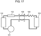
- FIG. 17 shows an internal configuration of a refrigerator using the conventional motor driving device described in PTL 1.
- a refrigeration cycle is formed of low-pressure shell compressor 101, condenser 102, dryer 103, capillary tube 104 and evaporator 105 in this order.
- the refrigerant flows in the refrigeration cycle from compressor 101 to condenser 105.
- Four-way valve 106 connects inlet A and the dryer 103 to each other, connects outlet B and capillary tube 104 to each other, connects inlet C and evaporator 105 to each other, and connects outlet D and compressor 101 to each other.
- four-way valve 106 causes inlet A to communicate with outlet B, and causes inlet C to communicate with outlet D.
- four-way valve 106 causes inlet A to communicate with outlet D, and causes inlet C to communicate with outlet B.
- a normal refrigeration cycle is formed to enable a regular cooling operation.
- compressor 101 can be started in a state in which the high pressure side and the low pressure side are separated from each other on the cycle, the high-pressure refrigerant is supplied from the dryer to the compressor 101, the pressure difference between suction and discharge of compressor 101 is reduced, and load torque fluctuations are small.
- This configuration prevents the high-pressure side refrigerant from flowing into evaporator 105 and the rise in temperature of evaporator 105 during the stoppage of the refrigeration cycle. This makes it possible to reduce a loss of energy in the refrigeration cycle.
- the conventional motor driving device and the refrigerator using the same are configured to detect a rotational position of a rotor of the brushless DC motor and to switch a stator winding to be energized based on the rotational position thereof.
- a detector such as an encoder and a Hall element is not used, but in general, there is used a digital sensorless mode for comparing an inverter output voltage and 1/2 of an inverter input voltage with each other and detecting a point where a magnitude relationship therebetween changes (for example, see NPL 1).
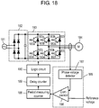
- FIG. 18 shows a block diagram of a motor driving device of NPL 1.
- the conventional motor driving device uses commercial power source 181 as an input, converts an alternating current (AC) voltage into a direct current (DC) voltage by a rectifying/smoothing circuit 182, and inputs the DC voltage to inverter 183.
- inverter 183 six switching elements 183a to 183f are connected to one another in the form of a three-phase full bridge, and diodes 183g to 1831 are respectively connected in parallel in an opposite direction to switching elements 183a to 183f. In this way, inverter 183 converts the DC input into three-phase AC power and supplies the power to brushless DC motor 184.
- Position detection circuit 185 detects a relative position of the rotor based on terminal voltages of brushless DC motor 184.
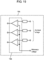
- FIG. 19 is a circuit diagram of position detection circuit 185 of the motor driving device of NPL 1.
- position detection circuit 185 in NPL 1 is composed of comparator 186 realized by comparators.
- the terminal voltages of brushless DC motor 184 are input to non-inverting inputs of comparator 186, and a voltage of 1/2 of the inverter input voltage is input as a reference voltage to inverting inputs of comparator 186.
- a position signal with regard to an induced voltage appearing at such an inverter output terminal in a non-energized phase in the stator winding, timing at which a magnitude relationship of the induced voltage with the reference voltage changes (that is, a zero-cross point of the induced voltage) is detected, and a detection result is output.
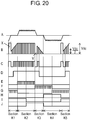
- FIG. 20 is a diagram showing waveforms including current waveform A and terminal voltage waveform B at a time of sensorless driving of the motor driving device according to NPL 1. It is graph C that shows a comparison result showing a magnitude relationship of terminal voltage waveform B with the reference voltage (1/2 voltage of the inverter input).
- Output waveform D of position detection circuit 185 is a waveform obtained by removing an influence of switching by PWM control and an influence of spike voltage X and spike voltage Y from such a waveform C by waveform processing.
- spike voltage X and spike voltage Y are generated when energy of the winding to which voltage supply is interrupted by commutation is released as a reflux current.
- Timing (a rising edge or a falling edge) at which a signal state of waveform D changes is detected as position detection, and brushless DC motor 184 can be stably driven by repeating the commutation based on this position signal.
- FIG. 21 is a block diagram showing a conventional motor driving device described in PTL 3.
- the conventional motor driving device includes: brushless DC motor 214 composed of a rotor having a permanent magnet and a stator having a three-phase winding; inverter 213 that supplies power to the three-phase winding; and driver 215 that drives inverter 213.
- the conventional motor driving device further includes a position detector 216 that detects a relative rotational position of the rotor based on an induced voltage generated in a stator winding of brushless DC motor 214 and then outputs a position signal.
- the conventional motor driving device includes: first waveform generator 217 that outputs a rectangular wave or a sine wave or a waveform similar to these waveforms while performing duty control based on the signal output from position detector 216; and a second waveform generator 219 that outputs a rectangular wave or a sine wave or a waveform similar to these waveforms to brushless DC motor 214.
- the conventional motor driving device includes switching determiner 219 that drives inverter 213 by the output of first waveform generator 217 when brushless DC motor 214 is rotating at a low speed equal to or lower than a predetermined rotation speed, and drives inverter 213 by the output of second waveform generator 218 when brushless DC motor 214 is rotating at a high speed exceeding the predetermined rotation speed.
- the conventional motor driving device is configured to output a pattern for detecting the induced voltage of brushless DC motor 214 at predetermined timing when driven by second waveform generator 219.
- FIG. 20 for example, timing of commutation from section K2 to section K3 will be considered.
- energy accumulated in the U-phase winding is refluxed through an inside of brushless DC motor 184 via the switching element 183f and the diode 183j, which are shown in FIG. 18 , and is then consumed.
- diode 183j turns to a conductive state, and is thereby connected to a negative side of the inverter input voltage, and accordingly, spike voltage Y shown in FIG. 20 is generated in the terminal voltage waveform at the time of generation of the reflux current.
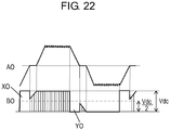
- FIG. 22 shows current waveform A0 and terminal voltage waveform B0, which are waveforms when the conventional motor driving device drives brushless DC motor 214 in a state in which the motor current in the sensorless driving is large.
- the conventional motor driving device as shown in FIG. 22 , since the current flowing through brushless DC motor 214 is high, the energy accumulated in the U-phase winding as a result that the supply of power to the U-phase winding itself is interrupted is large. Therefore, a release time of the energy, that is, each of a generation period of spike voltage X0 and spike voltage Y0, which are shown in FIG. 22 , becomes longer.
- spike voltage X0 and spike voltage Y0 cover and hide the zero-cross point of the induced voltage, so that the position signal cannot be detected.
- PTL 4 discloses a sensorless BLDC motor apparatus for providing a drive current allowing the rotor of the BLDC motor to be aligned in a predetermined direction during an initial position setting section (or for a first period of time), and providing a drive current allowing a frequency thereof to be varied at predetermined time intervals so as to accelerate the rotational speed of the BLDC motor during an open loop section (or for a second period of time), and a method using the same.
- PTL 5 discloses a method for operating a motor/compressor combination, especially for hermetically-encapsulated small refrigerating machines, comprises a compressor having a periodically operating displacement element, which is driven by a brushless motor. To start the motor, it is subjected to asynchronous and then synchronous commutation of its stator windings. For starting, the rotor is turned by asynchronous commutation from any given rest position to a starting position that facilitates running-up and is then started from that starting position.
- PTL 6 proposes a motor control device provided with detecting means detecting a current peak value and a current electrical angle based on phase currents.
- the motor control device further comprises startup means to output a startup voltage instruction value and a startup voltage phase instruction value to increase the rotational velocity of the synchronous motor.
- NPL 1 Motor/Inverter Technology for Home Appliance (original title is in Japanese)", edited and written by NAGATAKE Kazuo, published by The Nikkan Kogyo Shimbun, Ltd., April 28, 2000, pp. 88-91
- the present invention has been made in consideration of the above conventional problems and provides a refrigerator as defined in claim 1 which comprises a compressor and a motor driving device used for the compressor that stably starts up even while load torque fluctuations are large.
- the motor driving device employed in the present invention is capable of reliably detecting the position signal of the brushless DC motor even in the driving state in which high torque driving is required and a large motor current flows at starting and so on, and capable of realizing high torque driving performance including starting performance for the brushless DC motor, and in addition, provides a compressor driving device capable of stably starting a compressor.
- the motor driving device employed by the present invention includes: a brushless DC motor that drives a load that fluctuates during one rotation; a driver that applies a voltage to the brushless DC motor and drives the brushless DC motor; and a speed accelerator that determines the voltage to be applied by the driver.
- the speed accelerator is configured to accelerate the brushless DC motor such that a speed change rate of a speed within one rotation from start of the brushless DC motor with respect to a speed at next one rotation remains within a predetermined value or less.
- the speed accelerator is configured to accelerate the brushless DC motor such that a speed change rate of a speed within one rotation from the start of the brushless DC motor with respect to the speed of the next one rotation remains within a predetermined value or less under a condition where a change of the load during one rotation is maximized.
- the motor driving device is capable of being started under the condition where it is most difficult to make the start-up of the load driven by the brushless DC motor, and can be stably started under all the required conditions.
- the motor driving device employed by the present invention includes a position detector that detects a magnetic pole position of the brushless DC motor.
- the driver in a state of performing positioning of flowing a current to a specific phase of the brushless DC motor before the start of the motor driving device, and flowing a current to a phase advanced by 90 degrees or more from the phase positioned after the lapse of a predetermined time, the driver is configured to acquire the position information of the position detector, and to start to drive the motor driving device.
- driving is performed according to the magnetic pole position of the brushless DC motor, and therefore, even when the load fluctuates during one rotation and the speed greatly changes, the motor driving device can be stably driven.
- the motor driving device employed by the present invention is configured as a drive device that drives the compressor. By being driven by the motor driving device, the compressor can be stably started.
- the refrigerator according to an embodiment of the present invention may include a compressor driven by the motor driving device, and the compressor may be configured to be started in a state in which a pressure difference between a suction side and discharge side of the compressor remains.
- This configuration allows the motor driving device to start even in a state in which there is the pressure difference between the suction side and discharge side of the compressor, thereby making it possible to reduce an energy loss in a refrigeration cycle without raising a temperature of the evaporator with a simple system configuration at low cost.
- the refrigerator according to an embodiment of the present invention may be configured such that the pressure difference between the suction side and discharge side of the compressor is larger than at least 0.05 MPa. This configuration can reduce the energy loss in the refrigeration cycle while reducing the progress of deterioration due to the increase in vibration and maintaining the reliability of the compressor.
- a first exemplary motor driving device includes: a rectifying/smoothing circuit composed of a rectifier that rectifies an AC voltage and a smoother made of a capacitor that converts an output voltage of the rectifier into a stable DC voltage; a brushless DC motor composed of a rotor having a permanent magnet and a stator having a three-phase winding; and an inverter having six switching elements connected to one another in a three-phase bridge configuration, the inverter receiving the output of the rectifying/smoothing circuit and supplying power to the three-phase winding.
- the motor driving device includes: a position detector that detects a rotational position of the rotor; a speed detector that detects a speed of the brushless DC motor based on a signal from the position detector; an energized phase determiner that determines an energized phase of the stator winding based on the detected rotational position and driving speed of the rotor; and an error detector that detects an error between the speed detected by the speed detector and a target speed.
- the motor driving device includes: a PWM controller that adjusts an output voltage of the inverter by PWM control by ON chopping or OFF chopping of any one of the switching elements of the inverter such that the speed of the brushless DC motor becomes the target speed; and a drive waveform generator that generates a drive waveform of the inverter.
- the motor driving device is configured to select the one of the switching elements, the switching element performing the chopping by PWM control, such that a current for charging the capacitor of the smoother flows from the winding, to which supply of power is interrupted, when the energized winding of the brushless DC motor is switched.
- the first exemplary motor driving device may be configured as a driving device that drives the compressor.
- the compressor driven by the motor driving device can be promptly restarted even in a state in which large starting torque is required due to the pressure difference between the suction side and discharge side of the compressor. In this way, a stopping period of the compressor can be shortened, and the compressor can be stably started.
- a refrigerator may include: a condenser that condenses the high-temperature and high-pressure gas refrigerant compressed by the compressor; a decompressor that decreases the pressure of the liquid refrigerant liquefied by the condenser; and an evaporator that evaporates the liquid refrigerant whose pressure is decreased by the decompressor.
- the refrigerator according to an embodiment of the present invention may include a refrigerant flow rate adjuster that shuts off a refrigerant flow path between the condenser and the evaporator, and may be configured such that, while the compressor is being stopped, the refrigerant flow path between the condenser and the evaporator is shut off by the refrigerant flow rate adjuster.
- the refrigerator according to an embodiment of the present invention may be configured such that, when the compressor is started from the stopped state, a pressure difference equal to or larger than a predetermined value is added between the suction-side pressure and discharge-side pressure of the compressor.
- the compressor can be started from substantially the same pressure state as while the compressor is being driven. Therefore, soon after the compressor is started, the pressure between the suction side and discharge side of the compressor can return to the stable pressure state during the operation of the compressor. Hence, the loss of the refrigeration cycle until the compressor returns to the stable pressure state after being started can be reduced to a large extent.
- the refrigerator according to an embodiment of the present invention may include the above-described motor driving device, or a driving device of a compressor, which is composed of the above-described motor driving device.
- the refrigerator according to an embodiment of the present invention may include a compressor driven by the above-described motor driving device.
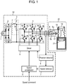
- FIG. 1 is a block diagram showing a motor driving device in an embodiment of the present invention.
- motor driving device 30 is connected to AC power source 1, and drives brushless DC motor 5.
- AC power source 1 is a general commercial power source, which is a 50 Hz or 60 Hz power source with an effective value of 100 V in Japan. A configuration of motor driving device 30 will be described below.
- Rectifier circuit 2 rectifies AC power input from AC power source 1 into DC power, and is composed of four rectifying diodes 2a to 2d which are bridge-connected to each other.
- Smoother 3 is connected to an output side of rectifier circuit 2, and smooths an output from rectifier circuit 2. Smoother 3 is composed of smoothing capacitor 3e and reactor 3f. An output from smoother 3 is input to inverter 4.
- reactor 3f since reactor 3f is inserted between AC power source 1 and capacitor 3e, reactor 3f may be located either before or after rectifying diode 2a to 2d. Moreover, when a common mode filter forming a high-frequency remover is provided in the circuit, reactor 3f is constituted in consideration of a composite component with a reactance component of the high-frequency remover.
- Inverter 4 converts DC power, which contains large ripple components at a period twice a power source period of AC power source 1 in a voltage from smoother 3, into AC power.
- Inverter 4 is formed by three-phase bridge-connecting six switching elements 4a to 4f.
- six reflux current diodes 4g to 4l are respectively connected to switching elements 4a to 4f in an opposite direction (in a direction opposite to a direction where switching elements 4a to 4f flow currents).
- Brushless DC motor 5 is composed of rotor 5a having a permanent magnet and stator 5b having a three-phase winding. Brushless DC motor 5 rotates rotor 5a by making a three-phase AC current, which is generated by inverter 4, flow in the three-phase winding of stator 5b.
- Position detector 6 detects a magnetic pole position of rotor 5a based on an induced voltage generated in the three-phase winding of stator 5b, a current flowing in the three-phase winding of stator 5b, a voltage applied to the three-phase winding, and the like.
- position detector 6 acquires a terminal voltage of brushless DC motor 5, and detects a relative magnetic pole position of rotor 5a of brushless DC motor 5. Specifically, position detector 6 detects a relative rotational position of rotor 5a based on the induced voltage generated in the three-phase winding of stator 5b. Moreover, position detector 6 detects a zero-cross point by comparing the induced voltage and a reference voltage with each other.
- a voltage serving as the reference voltage of the zero-cross point of the induced voltage may be a voltage of a virtual midpoint generated from terminal voltages for three phases, or may be a voltage of an acquired DC bus voltage. In this embodiment, the voltage of the virtual midpoint is defined as the reference voltage.
- a mode for detecting the relative magnetic pole position of rotor 5a based on the induced voltage has a simple configuration, and enables lower cost.
- Speed detector 7 calculates a current driving speed of brushless DC motor 5 from position information detected by position detector 6. In this embodiment, speed detector 7 measures a time from the detection of the zero-cross point of the induced voltage, and calculates the current speed based on the measured time.
- Speed accelerator 8 calculates a voltage to be applied to brushless DC motor 5 based on the current speed detected by speed detector 7.
- the voltage to be applied in speed accelerator 8 there may be used such proportional control of changing magnitude of the applied voltage according to a difference between a target speed rising with the lapse of time and the current speed.
- the applied voltage may be determined by a predetermined voltage change rate such that the target speed can be reached under a condition where a load change is maximum to make acceleration most difficult.
- the target speed is determined based on a degree of acceleration. For example, an initial target speed and applied voltage are fixed, and the target speed is determined based on magnitude of the speed detected by speed detector 7 as a result of applying the voltage.
- the target speed is set smaller as the result of speed detector 7 is larger, and the target speed is set larger as the result of speed detector 7 is smaller.
- the level at which the speed change is not a problem refers to a state in which a speed change rate when pressures of a suction side and discharge side of the compressor are balanced and a speed change rate when the pressures have a difference therebetween are substantially the same.
- the fact that the pressures of the suction side and discharge side of the compressor are balanced refers to a state in which the pressure difference between the suction and discharge of the compressor enables the compressor to function by a conventional starting method and does not allow the vibrations to affect reliability.
- the pressure difference shall be 0.05 MPa or less.
- the speed change rate when the pressure difference between the suction side and discharge side of the compressor is the maximum is defined as a value obtained by dividing a minimum speed at the time of one rotation from a certain point of time by an initial speed of the one rotation. For example, if the speed at a certain point of time is 3 r/s, and the minimum speed when one rotation is made from this is 2.7 r/s, then the speed change rate is 0.9 as a result of dividing 2.7 by 3.
- this embodiment there is adopted a mode for determining the applied voltage after determining the voltage change rate in advance.
- This mode has an extremely simple configuration, and accordingly, enables the system to be constructed at lower cost.
- speed accelerator 8 receives a speed command (target driving speed) input from the outside, and starts to output an applied voltage command for the start-up.
- Driver 9 outputs supply timing of power to be supplied by inverter 4 to the three-phase winding of brushless DC motor 5 and a drive signal for PWM control based on position information of rotor 5a of the brushless DC motor, the position information being detected by position detector 6.
- the drive signal turns on or off switching elements 4a to 4f of inverter 4. With this operation, optimal AC power is applied to stator 5b to rotate rotor 5a and to drive brushless DC motor 5.
- Drive waveforms include rectangular waves and sine waves; however, are not particularly limited to these.
- driver 9 calculates and outputs a PWM duty width based on the applied voltage set by speed accelerator 8.
- driver 9 which phase is to be energized is determined based on information from position detector 6.
- motor driving device 30 since motor driving device 30 is driven by a 120-degree rectangular wave, switching elements 4a, 4c and 4e of an upper arm are energized while being shifted by 120 degrees from one another.
- switching elements 4b, 4d and 4f of a lower arm are also energized while being shifted by 120 degrees from one another.
- OFF periods at intervals of 60 degrees exist between energization periods of switching elements 4a and 4b, between energization periods of switching elements 4c and 4d, and between energization periods of switching elements 4e and 4f.
- driver 9 energizes at least two arbitrary phases of brushless DC motor 5, for example, for one second such that the position of rotor 5a comes to a specific magnetic pole position. Thereafter, driver 9 energizes a phase advanced by 90 degrees to 150 degrees from such a phase that was being energized, and waits for position detector 6 to detect the position of the rotor of brushless DC motor 5.
- the state shifts to a normal driving state in which such an energized phase is switched to a next phase.
- the phases being energized are energized until the state of the phases turns to a state in which the phases are delayed by 90 degrees from such a state in which brushless DC motor 5 is normally driven after being started.
- the phases at the time of starting motor driving device 30 can be surely fixed, and further, the phases to be energized next are advanced by 90 degrees to 150 degrees, whereby the same state of the energized phases as the state of the normal driving can be established. Therefore, large output torque of brushless DC motor 5 can be ensured, and further, start-up vibrations due to a phase delay can be reduced.
- a freezer and a refrigerator each of which uses motor driving device 30 in this embodiment.
- the refrigerator will be described below as an example; however, the same applies to the freezer.
- Refrigerator 22 is mounted with compressor 17.
- Compressor 17 is composed of brushless DC motor 5, a crankshaft, a piston, and a cylinder. A rotational motion of rotor 5a of brushless DC motor 5 is converted into a reciprocating motion by the crankshaft. The piston connected to the crank shaft reciprocally moves in the cylinder, thereby compressing a refrigerant in the cylinder.
- An arbitrary compression mode such as a rotary -type compression mode and a scroll-type compression mode is used as a compression mode (mechanical mode) of compressor 17.
- the compression mode is a reciprocating-type one will be described.
- Reciprocating-type compressor 17 causes large torque fluctuations in suction and compression processes, resulting in large fluctuations in speed and current value.
- Refrigerator 22 is composed by mounding such a refrigeration cycle as described above thereon.
- two-way valve 18 an electromagnetic valve openable/closable by energization, or the like is used.
- two-way valve 18 is opened, causes compressor 17 and condenser 19 to communicate with each other, and flows the refrigerant between compressor 17 and condenser 19. Meanwhile, during stoppage of compressor 17, two-way valve 18 is closed, and closes a space between compressor 17 and condenser 19 to prevent the refrigerant from flowing therebetween.
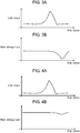
- an axis of abscissas indicates a phase of the magnetic pole position of rotor 5a of brushless DC motor 5.
- An axis of ordinates in each of FIGS. 2A , 3A and 4A indicates load torque driven by brushless DC motor 5.
- An axis of ordinates in each of FIGS. 2B , 3B and 4B indicates the driving speed of brushless DC motor 5.
- FIG. 2A shows a change in the load torque applied to brushless DC motor 5 at one rotation when the pressure difference between the suction side and discharge side of compressor 17 is 0.05 MPa.
- the pressure difference of 0.05 MPa is a maximum pressure difference which can be regarded as being balanced as the pressure difference between the suction side and discharge side of the conventional compressor, and is a maximum allowable pressure difference in terms of the operation of compressor 17. That is, a speed change rate at the maximum pressure difference allowed at the time of start-up when the speed change rate is largest becomes the maximum allowable speed change rate.
- FIG. 2B shows a change in the speed of the brushless DC motor at the maximum pressure difference that can be regarded as being balanced. An initial speed represents 3r/s which is a speed of the conventional synchronous operation, and FIG. 2B shows a speed change when brushless DC motor 5 makes one rotation at this initial speed. That is, when the pressure difference between the suction side and discharge side of compressor 17 is 0.05 MPa, only the speed change rate shown in FIG. 2B is allowed in compressor
- FIG. 3A shows a change in the load torque at one rotation of brushless DC motor 5 under conditions that the pressure difference between the suction side and discharge side of compressor 17 is 0.25 MPa, which means that the load applied to brushless DC motor 5 is increased about five times that in FIG. 2A .
- This pressure difference of 0.25 MPa is a maximum pressure difference in the configuration of compressor 17 mounted on refrigerator 22 of the this embodiment, and this is a maximum load (maximum load change) to be driven while brushless DC motor 5 makes one rotation.
- FIG. 3B shows a change in the speed of the brushless DC motor at one rotation at this time. As in FIG. 2B , the initial speed is 3 r/s which is the conventional synchronous operation speed. Such a speed change at this time is larger than that in FIG. 2B . The speed change rate increases, and the vibrations are greatly increased.
- FIG. 4A shows the load torque applied to brushless DC motor 5 when the pressure difference between the suction side and discharge side of compressor 17 is 0.25 MPa.
- FIG. 4B shows a speed change when motor driving device 30 in this embodiment sets the target speed, which is to be reached within one rotation of brushless DC motor 5, as the initial speed.
- FIG. 4B shows a speed change when the initial speed is set to about 6.71 r/s which is a speed obtained by multiplying the conventional start-up speed by a square root of 5 under the condition of the load torque of FIG. 4A . That is, the target speed is 6.71 r/s.
- the speed change rate in FIG. 4B is the same as the conventional one.
- the speed change rate is proportional to the load by a square of the speed. Therefore, when the load becomes five times, the speed is multiplied by the square root of 5, whereby the speed change rate in this case can be equalized to the speed change rate at the driving speed under the load condition shown in FIG. 2A and FIG. 2B .
- FIG. 5 shows how much speed is required when the load changes in the case where the rotational speed is set to 3 r/s and the load in the following case of the pressure difference is set to 1.
- the pressure difference is a pressure difference between the suction side and discharge side of compressor 17, of which value is 0.05 MPa as the maximum pressure difference when the pressures on the suction side and the discharge side are balanced. From FIG. 5 , it is seen that, for example, if the load is increased to four times, the speed just needs to be set to 6 r/s, which is obtained by multiplying 3 r/s by 2 which is a square root of 4.
- a multiplication factor for example, five times
- the load change at the maximum pressure difference between the suction side and discharge side of compressor 17 is multiplied by the square root, whereby the target speed required for the system such as refrigerator 22 is obtained, and the speed of brushless DC motor 5 is caused to reach the obtained target speed within one rotation of brushless DC motor 5 itself. In this way, the vibrations of compressor 17 can be suppressed.
- the speed change which occurs within one rotation of brushless DC motor 5 from the start-up of motor driving device 30, applies force to a state in which an object of which reliability is a problem, such as compressor 17 affected by the speed change, is not vibrating. Therefore, due to inertial force of the object such as compressor 17, which is affected by the speed change, compressor 17 is hardly affected by the speed change, and this does not lead to a problem. However, as the rotation of brushless DC motor 5 continues and the speed change continues, compressor 17 is greatly affected.
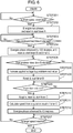
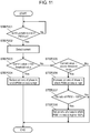
- the drive control for motor driving device 30 is called by a command from the outside during stoppage of compressor 17 to start brushless DC motor 5, and is ended by the fact that the driving speed of brushless DC motor 5 reaches the target speed and the starting of brushless DC motor 5 is completed.
- speed accelerator 8 determines whether or not there is a speed command that issues an instruction on the speed for driving compressor 17. If there is no speed command, the process proceeds again to STEP 201, and if there is a speed command, the process proceeds to STEP 202. Here, it is determined that there is no speed command yet, and the process proceeds to STEP 201.
- driver 9 in order to prepare the start-up, driver 9 energizes arbitrary two phases of brushless DC motor 5, starts to flow a current through the phases, and resets and starts timer A. At this time, speed accelerator 8 adjusts the applied voltage such that the current is less than a current demagnetizing the permanent magnet of rotor 5a of brushless DC motor 5 and less than the current at which inverter 4 breaks. Then, the process proceeds to STEP 203.
- driver 9 determines whether or not timer A shows a time equal to or more than predetermined time A. If the time of timer A is equal to or more than predetermined time A, then the process proceeds to STEP 204, and if the time of timer A is less than predetermined time A, then the process proceeds to STEP 203. Here, it is determined that predetermined time A has not elapsed, and the process proceeds to STEP 203 again.
- timer A and predetermined time A are compared with each other, and the above-described determination is made. That is, the process is on standby in STEP 203 until predetermined time A has elapsed since the start of the energization to brushless DC motor 5, and the current continues to flow to two phases of brushless DC motor 5, and the phase is fixed.
- Predetermined time A just needs to be a time while the phase is sufficiently fixed, and for example, is one second in this embodiment.
- driver 9 starts to energize a phase advanced by 120 degrees from the phase determined from the arbitrary two phases started to be energized in STEP 202, and thereafter, resets and starts timer B and timer C. If switching element 4a and switching element 4d are energized in STEP 202, then switching element 4c and switching element 4f are energized in STEP 204. Then, the process proceeds to STEP 205.
- driver 9 determines whether or not timer B shows a time equal to or more than predetermined time B. If the time of timer B is equal to or more than predetermined time B, then the process proceeds to STEP 208, and if the time of timer B is less than predetermined time B, then the process proceeds to STEP 206. Here, it is determined that the time of timer B is less than predetermined time B because the energization in STEP 204 has just started, and the process proceeds to STEP 206.
- STEP 206 it is determined whether or not the position detector 6 has been able to detect the position of brushless DC motor 5. If position detector 6 has been able to detect the position, then the process proceeds to STEP 210, and if position detector 6 has not been able to detect the position, then the process proceeds to STEP 207. Here, it is determined that such position detection has not been enabled because the energization in STEP 204 has just started, and the process proceeds to STEP 207.
- STEP 207 it is determined whether or not the speed detected by speed detector 7 has reached the speed (the rotation speed of the brushless DC motor) required for the speed change rate of the next one rotation to be equal to or less than the predetermined value. If the detected speed has reached the target speed, the process is ended, and if the detected speed has not reached the target speed, the process proceeds again to STEP 205.
- the target speed is a maximum load when the pressures of the suction side and discharge side of compressor 17 are considered to be balanced, and is obtained from the case of the start-up at the conventional speed. If it is assumed that the conventional speed is 3 r/s and the load is increased to five times, the target speed becomes about 6.71 r/s. Here, since the position detection has not been performed yet, the process returns to STEP 205 again.
- driver 9 determines whether or not timer B shows the time equal to or more than predetermined time B. Here, it is determined that a series of the processing has been performed and that predetermined time B has elapsed, and the process proceeds to STEP 208.
- an applied voltage command value is added to a current applied voltage command value by a constant value.
- a value at which the target driving speed can be reached within one rotation of brushless DC motor 5 under the maximum load condition in this embodiment is determined in advance by experiment or simulation. Then, the process proceeds to STEP 209.
- timer B is reset and restarted in order to determine next timing of increasing the applied voltage, and the process proceeds to STEP 206.
- the position detection is performed after a lapse of a certain time from the start of the energization in STEP 204, and the process proceeds to STEP 210 if position detector 6 can detect the position of brushless DC motor 5.
- STEP 210 a value of timer C is acquired, and timer C is restarted after timer C is reset. Timer C displays a duration of a current applied voltage pattern. Then, the process proceeds to STEP 211.
- the speed is calculated by taking a reciprocal number of the acquired value of timer C, and the process proceeds to STEP 212.
- STEP 212 an energization pattern in which phases are advanced by 60 degrees from the current energized phases is applied, and the process proceeds to STEP 207.
- the process is performed for a while since the process is called during the stoppage of compressor 17 until the start-up is completed, and thus compressor 17 can be started without large vibrations even under the load condition where the pressure difference between the suction side and discharge side of compressor 17 is larger than 0.05 MPa.
- motor driving device 30 of this embodiment is used for compressor 17 and is mounted on refrigerator 22.
- two-way valve 18 When compressor 17 is started up, two-way valve 18 is simultaneously opened to cause the outlet of compressor 17 and condenser 19 to communicate with each other. Although two-way valve 18 is to be opened at the same time as the start-up of compressor 17, no problem arises even when two-way valve 18 is opened slightly before or after the start-up. Continuously driving compressor 17 will increase a pressure in condenser 19 and reduce a pressure in evaporator 21 through decompression by decompressor 20.
- motor driving device 30 can be started only when the pressure difference between the suction side and discharge side of compressor 17 is equal to or less than 0.05 MPa in the conventional case. Therefore, it is necessary to wait for 10 minutes to elapse.
- two-way valve 18 can simply compose a system such as a refrigerator, and can maintain a pressure difference between the suction side and discharge side of compressor 17.
- motor driving device 30 of this embodiment includes: brushless DC motor 5 that drives the load of which magnitude fluctuates during one rotation of brushless DC motor 5; and driver 9 that applies a voltage to brushless DC motor 5 and drives brushless DC motor 5.
- Motor driving device 30 of this embodiment further includes speed accelerator 8 configured to determine the voltage to be applied by driver 9 so as to accelerate brushless DC motor 5 such that the speed change rate of the speed of brushless DC motor 5 within one rotation from the start with respect to the speed at the next one rotation remains within the predetermined value or less.
- speed accelerator 8 may be configured to accelerate brushless DC motor 5 such that the speed change rate, which indicates the degree how the speed of brushless DC motor 5 within one rotation from the start changes with respect to the speed of the next one rotation, remains within the predetermined value or less under the load condition calculated from the maximum load change during one rotation of brushless DC motor 5.
- motor driving device 30 of this embodiment may include position detector 6 that detects the magnetic pole position of brushless DC motor 5.
- driver 9 performs positioning of flowing a current to a specific phase of brushless DC motor 5 before the start-up of motor driving device 30, and flows a current to a phase advanced by 90 degrees or more from the phase positioned after the lapse of a predetermined time. Then in this state, driver 9 acquires the position information from position detector 6, and starts to drive motor driving device 30.
- refrigerator 22 in which motor driving device 30 of this embodiment is used, motor driving device 30 drives compressor 17 in the refrigeration cycle in which the constituents are connected to one another in order of compressor 17, condenser 19, decompressor 20, evaporator 21 and compressor 17.
- refrigerator 22 of this embodiment is configured to start motor driving device 30 in a state in which the pressure difference between the suction side and discharge side of compressor 17 remains. With such a configuration, even in a state in which the pressure difference exists between the suction side and discharge side of compressor 17, motor driving device 30 can be started. In this way, with a simple system configuration and at low cost, the temperature of evaporator 21 is not allowed to be raised, and an energy loss in the refrigeration cycle can be reduced.
- motor driving device 30 of this embodiment may be configured such that the pressure difference between the suction side and discharge side of compressor 17 is larger than at least 0.05 MPa. With such a configuration, even when there is a pressure difference at which vibration normally increases, acceleration of a deterioration due to the increase in vibration can be reduced, and the energy loss in the refrigeration cycle can be reduced while maintaining the reliability of compressor 17.
- FIG. 7 is a block diagram showing the exemplary motor driving device.
- the same reference numerals are assigned to the same components as those in the embodiment shown in FIG. 1 , and a description thereof will be omitted.
- rectifier circuit 2, smoother 3 and inverter 4, which compose motor driving device 82, and brushless DC motor 5, which composes refrigerator 22, have the same configurations as those in the embodiment shown in FIG. 1 .
- position detector 76 of motor driving device 82 of this exemplary motor driving device has the same configuration as that of position detector 6 of the embodiment shown in FIG. 1 .
- Speed detector 77 calculates a current driving speed of brushless DC motor 5 and an average speed of one past rotation from position information detected by position detector 76.
- speed detector 77 measures a time from the detection of the zero-cross point of the induced voltage, and performs calculation for this measured time as the current speed.
- speed detector 77 detects an interval between such induced voltage zero-cross points as an interval elapsed time, calculates a sum of the interval elapsed times in the one past rotation, and calculates the average speed of one rotation of brushless DC motor 5 from a result of the calculation.
- Speed controller 78 compares the average speed of one rotation of brushless DC motor 5, which is detected by speed detector 77, and the target speed with each other. If the target speed is higher than the average speed of one rotation, then the applied voltage to brushless DC motor 5 is set so as to rise. If the target speed is lower than the average speed of one rotation, then the applied voltage to brushless DC motor 5 is set so as to drop. If the average speed of one rotation of brushless DC motor 5 and the target speed coincide with each other, then the applied voltage to brushless DC motor 5 is set so as to be maintained.
- Current detector 79 detects the current flowing through brushless DC motor 5. As the current to be detected, a current flowing through each phase of brushless DC motor 5 may be detected, or a DC bus current flowing through inverter 4 may be detected. In the case of detecting the DC bus current of inverter 4, if the DC bus is detected as a total current flowing through brushless DC motor 5, then a current of a peak flowing through the three phases can be detected, and accordingly, it is unnecessary to decompose the currents flowing through the respective phases.
- current detector 79 detects the current by, for example, inserting a DC current sensor, a resistor for current detection or the like in series.
- the current can be detected with high accuracy, and therefore, finer control can be performed.
- a circuit of motor driving device 82 can be configured at low cost.
- accuracy can be improved by using an amplifier, filter circuit and the like for the voltage. Even when the amplifier, the filter circuit and the like, which are as described above, are used, it is generally inexpensive to use the resistor rather than the current sensor.
- Exemplary motor driving device 82 uses the resistor, and is configured to detect the current between such DC buses of inverter 4.
- Applied voltage changer 80 corrects the PWM ON ratio determined by speed controller 78. If the current, which is input to applied voltage changer 80 and is detected by current detector 79, is higher than a first threshold value, then the PWM ON ratio determined by speed controller 78 is reduced. Meanwhile, if the current detected by current detector 79 is lower than a second threshold value, then the PWM ON ratio determined by speed controller 78 is increased.
- the first threshold value is set to a value smaller than a value obtained by subtracting a maximum value of a current, which increases in one carrier, from a value of a current that is not desired to be actually flown through brushless DC motor 5 and inverter 4.
- the first threshold value is set to 3 A, which is a current value smaller than values obtained by subtracting such a maximum current value, which increases in one carrier, from a rated current of inverter 4 and a demagnetization current of brushless DC motor 5.
- the second threshold value just needs to be equal to or less than the first threshold value, and equal to or more than a current value minimum necessary to drive brushless DC motor 5.
- the second threshold value may be the same value as the first threshold value.
- the second threshold value is set to 2.75 A obtained by subtracting 0.25 A, which is the maximum current value that changes in one carrier, from the first threshold value.
- An amount of the PWM ON ratio to be changed by applied voltage changer 80 may be fixed, or may be subjected to PI control by using differences between the current value detected by current detector 79 and the first threshold value and the second threshold value.
- the circuit of motor driving device 82 an be realized with a simpler configuration, and when the amount of the PWM ON ratio is subjected to the PI control, the amount concerned can be suppressed more accurately at a current value closer to the threshold value.
- the amount of the PWM ON ratio to be changed by applied voltage changer 80 is fixed.
- Driver 81 has the same configuration as driver 9 of the embodiment described above. Moreover, driver 81 outputs the applied voltage, which is set by applied voltage changer 80, based on the PWM control.
- timing of a PWM timer is output from the driver 81 to current detector 79 in order to determine timing at which current detector 79 detects the current.
- Waveform A in FIG. 8 is a transition diagram showing a change in the load torque with respect to the phase of brushless DC motor 5 when the applied voltage is determined by the speed controller that belongs to the conventional mode.
- Waveform B in FIG. 8 is a transition diagram showing a change in the zero-cross point interval with respect to the phase of brushless DC motor 5 when the applied voltage is determined by the speed controller that belongs to the conventional mode.
- Waveform C in FIG. 8 is a transition diagram showing a change in the current value of brushless DC motor 5 with respect to the phase of brushless DC motor 5 when the applied voltage is determined by the speed controller that belongs to the conventional mode.
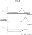
- Waveform A in FIG. 9 is a transition diagram showing a change in the load torque with respect to the phase of brushless DC motor 5 when the applied voltage is corrected by applied voltage changer 80 of this exemplary device.
- Waveform B in FIG. 9 is a transition diagram showing a change in the zero-cross point interval with respect to the phase of brushless DC motor 5 when the applied voltage is corrected by applied voltage changer 80 of this exemplary device.
- Waveform C in FIG. 9 is a transition diagram showing a change in the current value of brushless DC motor 5 with respect to the phase of brushless DC motor 5 when the applied voltage is corrected by applied voltage changer 80 of this exemplary device.
- each axis of abscissas represents a phase of brushless DC motor 5 after brushless DC motor 5 is started and allowed to make one rotation by the conventional start-up method in a state in which the pressure difference between the suction side and discharge side of compressor 17 is equal to or more than 0.05 MPa.
- each axis of abscissas represents a phase of brushless DC motor 5 after brushless DC motor 5 is started and allowed to make one rotation by the start-up method of this exemplary device in a state in which the pressure difference between the suction side and discharge side of compressor 17 is equal to or more than 0.05 MPa.
- Each axis of ordinates in waveform A in FIG. 8 and waveform A in FIG. 9 represents a change in the load torque applied to brushless DC motor 5.
- Each axis of ordinates in waveform B in FIG. 8 and waveform B in FIG. 9 represents an interval of detecting the zero-cross point to be detected by position detector 76.
- Each axis of ordinates in waveform C in FIG. 8 and waveform C in FIG. 9 represents the current flowing through brushless DC motor 5.
- both the load torque and such a zero-cross point detection interval change largely. Then, the peak of the increase in the load torque does not coincide with a peak of an actual increase of the zero-cross point detection interval, and there is a response delay in the zero-cross point detection interval with respect to the change in the load torque.
- exemplary motor driving device 82 in a similar way to the conventional start-up as shown in waveform A and waveform B in FIG. 9 , the load torque and the zero-cross point detection interval change greatly. Then, the peak of the increase of the load torque and the peak of the actual increase of the zero-cross point detection interval do not coincide with each other, and there is a response delay in the zero-cross point detection interval with respect to the change in the load torque.
- the PWM ON ratio is controlled to reduce the current when the current exceeds I1 that is the first threshold value and to increase the current when the current falls below I2 that is the second threshold value.
- motor driving device 82 can be started.
- motor driving device 82 can be started while reducing the speed change and reducing the vibration even under the condition where the load torque fluctuation is large.
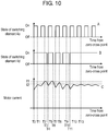
- Each axis of abscissas in waveform A, waveform B and waveform C in FIG. 10 represents a time from the zero-cross point.
- An axis of ordinates in waveform A in FIG. 10 represents a state of switching element 4a.
- An axis of ordinates in waveform B in FIG. 10 represents a state of switching element 4d.
- An axis of ordinates in waveform C in FIG. 10 represents a value of the current flowing through brushless DC motor 5.
- the switching element in one phase between the two energized phases is switched, and the switching element in the other phase is not switched, but is turned on for a full time.
- the element that is performing switching is switching element 4a, and the element that is turned on for a full time when it is not necessary to reduce the current is switching element 4d.
- the ON ratio of switching element 4a in the phase that is normally switched is not changed, but the ON ratio of switching element 4d that is normally turned on for a full time is changed.
- Switching element 4d is turned off between timing T3 and timing T4.
- the current decreases during a period from timing T2 to timing T3 while switching element 4a is turned off and switching element 4d is turned on.
- the current decreases more during a period from timing T3 to timing T4 while both of switching element 4a and switching element 4d are turned off. This occurs due to a difference between a state in which the current flowing through brushless DC motor 5 is refluxed and a state in which brushless DC motor 5 regenerates the current.
- switching element 4d decreases the OFF ratio and increases the ON ratio during a period from timing T10 to timing T11. This reduces the decreased amount of the current.
- the current value is lower than I2.
- the OFF ratio of switching element 4d is decreased, and the ON ratio of switching element 4d is changed such that switching element 4d is fully turned on.
- the current value is lower than I2.
- the ON ratio of the PWM in switching element 4d is 100%. Accordingly, the PWM ON ratio is not corrected any more. That is, the voltage is not corrected beyond the applied voltage value determined by speed controller 78.
- current detector 79 determines whether or not it is 5 ⁇ s before the ON state of the PWM ends (whether or not 5 ⁇ s is left before the ON state of the PWM ends). If it is 5 ⁇ s before, then the process proceeds to STEP 202, and if it is earlier than 5 ⁇ s, then the process proceeds again to STEP 201.
- the time of 5 ⁇ s is a time for ensuring a time required to detect the current while the PWM is on. If a time required by an analog-to-digital conversion circuit mounted on a microcomputer or the like is 1 ⁇ s, then 1 ⁇ s is sufficient.
- current detector 79 detects the current value of the DC bus of inverter 4, and the process proceeds to STEP 203.
- applied voltage changer 80 compares whether or not the current value detected in STEP 202 is larger than the predetermined first threshold value. If the detected current value is larger as a result of the comparison described above, then the process proceeds to STEP 204, and otherwise, the process proceeds to STEP 205. Here, it is determined that the current value is larger than the first threshold value, and the process proceeds to STEP 204.
- applied voltage changer 80 reduces the ON ratio of the phase having a high PWM ON ratio.
- the ON ratio of the PWM which is determined based on the applied voltage determined by speed controller 78, is set to the ON ratio of the PWM for switching element 4a. That is, when the PWM is not corrected by applied voltage changer 80, only switching element 4a is switched, and switching element 4d is turned on for the full time.
- the phase having a high PWM ON ratio is usually switching element 4d that is turned on for the full time. The PWM ON ratio of switching element 4d is reduced by a certain amount. Then, the processing is terminated.
- applied voltage changer 80 determines whether or not the current value detected in STEP 202 is smaller than the second threshold value. If the current value is smaller than the second threshold value, then the process proceeds to STEP 206, and otherwise, the process is terminated. Here, it is determined that the current value is smaller than the second threshold value, and the process proceeds to STEP 206.
- applied voltage changer 80 increases the ON ratio of the phase having a high ON ratio of the uncorrected PWM.
- switching element 4d is an object. Then, the process proceeds to STEP 207.
- applied voltage changer 80 determines whether or not the PWM ON ratio, which is corrected in STEP 206, exceeds 100%. If the PWM ON ratio exceeds 100%, then the process proceeds to STEP 208, and otherwise, that is, if the PWM ON ratio is equal to or less than 100%, then the process is terminated. Here, it is determined that the PWM ON ratio exceeds 100%, and the process proceeds to STEP 208.
- the first threshold value is set to a value sufficiently lower than these overcurrent protection and demagnetization current. Accordingly, even in a state of large load fluctuations, motor driving device 82 can be started while adopting a relatively low-capacity element for inverter 4 and while adopting a high-efficiency motor.
- exemplary motor driving device 82 is used for refrigerator 22 and is allowed to drive compressor 17.
- refrigerator 22 on which exemplary motor driving device 82 is mounted is configured such that motor driving device 82 is capable of being started even at a differential pressure of 0.05 MPa or more. Therefore, it is possible to start motor driving device 82 at timing when the refrigerator temperature rises and it is necessary to operate compressor 17.
- two-way valve 18 is provided between compressor 17 and condenser 19. At the starting time of compressor 17, two-way valve 18 is opened to cause compressor 17 and condenser 19 to communicate with each other. At the time of stoppage of compressor 17, two-way valve 18 is closed to close a space between compressor 17 and condenser 19. With this configuration, the difference between the suction pressure and the discharge pressure can be kept large even during the stoppage of compressor 17. This further increases an energy saving effect by starting motor driving device 82 from a state in which there is a pressure difference. Furthermore, in comparison with the case of using the four-way valve, in the case of using the two-way valve, the system configuration does not become complicated. Therefore, the system can be constructed at lower cost.
- exemplary motor driving device 82 includes: brushless DC motor 5 that drives the load fluctuating largely; and speed controller 78 that determines the voltage to be applied to brushless DC motor 5 and adjusts the speed.
- motor driving device 82 includes: current detector 79 that detects the current flowing through brushless DC motor 5; applied voltage changer 80 that reduces the applied voltage, which is determined by speed controller 78, when the current detected by current detector 79 is larger than the first threshold value; and driver 81 that drives brushless DC motor 5 with the applied voltage determined by applied voltage changer 80. With such a configuration, the current rise is suppressed, and motor driving device 82 can be started.
- This current rise is caused by that the increase in the load reduces the speed and induced voltage of brushless DC motor 5 to increase the difference between the induced voltage and the applied voltage. Therefore, motor driving device 82 can be started without using the four-way valve or the like even in a state in which there is a pressure difference. Moreover, it is possible to achieve energy saving by the use of a high-efficiency motor with a small demagnetization current and to achieve a reduction in cost by the use of an element with a small current rating.
- exemplary motor driving device 82 when the current detected by current detector 79 is smaller than the second threshold value, applied voltage changer 80 raises the voltage to an upper limit of the applied voltage determined by speed controller 78. In this way, in a section in which the required torque is small and the speed is slow, excessive output torque is suppressed, whereas the output torque is increased in a section in which the torque is insufficient and the speed is high. With such a configuration, even under the condition where the load torque fluctuation is large, motor driving device 82 can be started while decreasing the speed change and reducing the vibration.
- driver 81 performs the PWM control in order to adjust the voltage to be applied to brushless DC motor 5.
- speed controller 78 determines the PWM ON ratio in order to determine the voltage to be applied, and reduces the PWM ON ratio determined by speed controller 78 in order to reduce the voltage to be applied by applied voltage changer 80.
- exemplary motor driving device 82 when applied voltage changer 80 reduces the PWM ON ratio, at least a period for turning off all the energization is provided. In this way, brushless DC motor 5 is brought into a regenerative state, and the reduction rate of the current becomes larger than that in the reflux state. Therefore, it is possible to suppress the current more reliably.
- exemplary motor driving device 82 includes compressor 17 in which brushless DC motor 5 is incorporated.
- the load to be driven by brushless DC motor 5 is a compression element (crankshaft, piston or the like) of compressor 17.
- motor driving device 82 can be started even in a state in which the pressure difference remains in compressor 17, and in which a large load torque fluctuation exists from the start. Therefore, motor driving device 82 can be started without monitoring the state of compressor 17, thus making it possible to construct an inexpensive system.
- compressor 17 constructs a refrigeration cycle in which the constituents are connected to one another in order of compressor 17, condenser 19, decompressor 20, evaporator 21 and compressor 17.
- Motor driving device 82 is started in a state in which the pressure difference between the suction side and discharge side of compressor 17 remains. This configuration allows motor driving device 82 to start even in a state in which there is a pressure difference between the suction side and discharge side of compressor 17, thereby making it possible to reduce an energy loss in the refrigeration cycle without raising a temperature of evaporator 21 with a simple system configuration at low cost.
- compressor 17 can be immediately started up, thus quickly providing cooling to the inside of refrigerator 22 even in a bad power supply condition where power fails frequently.
- the pressure difference generated between the suction side and discharge side of compressor 17 is at least 0.05 MPa or more. This can reduce an energy loss in the refrigeration cycle while reducing a progress of deterioration due to the increase in vibration and maintaining reliability of compressor 17.
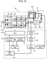
- FIG. 12 is a block diagram showing second exemplary motor driving device 120, disclosed herein for providing context of the present invention.
- power source 121 is a general commercial power source, and in the case of Japan, is an AC power source of 50 Hz or 60 Hz with an effective value of 100 V.
- Rectifying/smoothing circuit 122 is composed of rectifier 122a and smoother 122b, and receives power from AC power source 121, and converts an AC voltage into a DC voltage.
- rectifying/smoothing circuit 122 in this exemplary device has a voltage doubler rectification configuration
- rectifying/smoothing circuit 122 may have a full-wave rectification configuration, a configuration that switches between such full-wave rectification and such doubled voltage rectification, a power factor correction circuit (PFC), or the like.
- PFC power factor correction circuit
- inverter 123 six switching elements 123a to 123f are connected to one another in a three-phase full bridge configuration.
- Inverter 123 converts a DC input from rectifying/smoothing circuit 122 into AC power, and supplies the AC output with arbitrary voltage and frequency to brushless DC motor 124.
- Diodes 123g to 1231 are connected to switching elements 123a to 123f in parallel in a reverse direction, respectively.
- FIG. 12 shows an example in which the switching elements are composed of insulated-gate bipolar transistors (IGBTs); however, metal oxide semiconductor field-effect transistors (MOSFETs), bipolar transistors, silicon carbide (SiC) devices, gallium nitride (GaN) devices or the like may be used.
- IGBT insulated-gate bipolar transistors
- MOSFETs metal oxide semiconductor field-effect transistors
- SiC silicon carbide
- GaN gallium nitride
- Position detector 126 detects a magnetic pole position of a rotor of brushless DC motor 124. Position detector 126 detects, as a position signal, a zero-cross point of an induced voltage, which appears at a terminal to which a stator winding through which no current flows is connected, from the induced voltage.
- Speed detector 127 detects a driving speed of brushless DC motor 124 from an output signal interval of position detector 126.
- Error detector 128 detects a difference between the driving speed obtained by speed detector 127 and a commanded speed.
- PWM controller 129 adjusts a voltage, which is supplied to brushless DC motor 124 by inverter 123, from the difference between the commanded speed and the actual driving speed obtained from error detector 128. Specifically, switching elements 123a to 123f of inverter 123 are turned on or off at an arbitrary frequency by pulse width modulation (PWM), and an ON time (duty) per ON or OFF cycle is adjusted. The duty is adjusted and determined by feedback control such that the actual driving speed of the brushless DC motor coincides with the commanded speed as a target.
- PWM pulse width modulation
- energized phase setter 130 Based on the position signal obtained by position detector 126 and on timing of the detection, energized phase setter 130 sets an energization pattern and energization timing of a winding to be energized next. In addition, energized phase setter 130 adds a pattern for returning energy of a motor winding, to which the voltage application is cut off by commutation, as regenerative energy to a power supply side (that is, smoother 122b), and then outputs those settings to drive waveform generator 131.
- the energization pattern to the winding which is set by energized phase setter 130, is set such that a rectangular wave with 120 degrees or more and 150 degrees or less or a waveform similar thereto becomes a waveform with a predetermined frequency.
- Drive waveform generator 131 synthesizes the energization pattern and energization timing of the three-phase winding of brushless DC motor 124, which are provided by energized phase setter 130, with the PWM frequency and the ON time, which are set by PWM controller 129. In this way, drive waveform generator 131 generates drive waveforms for turning on or off respective switching elements 123a to 123f of inverter 123, and outputs the generated drive waveforms to driver 132.
- Driver 132 turns on or off respective switching elements 123a to 123f of inverter 123 based on the drive waveforms generated by drive waveform generator 131.
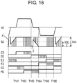
- FIG. 13 shows the waveforms of the respective units at the time of driving by motor driving device 120 of this exemplary device.
- waveform A1 represents a current waveform of the current flowing through the motor winding
- waveform B1 represents a motor terminal voltage. Both waveforms A1 and B1 are waveforms of the U phase.
- Waveforms C1 to H1 represent drive waveforms of respective switching elements 123a to 123f of inverter 123 by driver 132.
- Timings indicated by T131 to T136 are commutation timings at which the motor windings to be energized are switched.
- drive waveform generator 131 synthesizes: the output set by energized phase setter 130 in accordance with the energization pattern of the three-phase winding of brushless DC motor 124; the output waveform by PWM controller 129 based on the feedback control; and the pattern for returning the energy, which is stored and acquired in the winding, as regenerative energy to the power source side (electrolytic capacitor). Then, drive waveform generator 131 outputs a resultant of the synthesis to driver 132.
- switching elements 123a and 123f are in the ON state.
- a motor current is in a power running state of sequentially passing through switching element 123a, the U-phase winding, the W-phase winding and switching element 123f and returning to the power source side.
- diode 123j is made conductive, and energy stored in the U-phase winding is refluxed and consumed in a closed circuit composed of diode 123j, the U-phase winding, the W-phase winding, and switching element 123f.
- W-phase lower switching element 123f is turned off for an arbitrary period.
- the energy stored in the U-phase winding makes diode 123j and diode 123i conductive, and returns as generative energy to the power source (charging current of the smoothing capacitor).
- switching element 123f is turned on again. Then, the motor current returns to the power running state of sequentially passing through switching element 123b, the V-phase winding, the W-phase winding, and switching element 123f and returning to the power source side.
- the pattern for returning the winding energy at the time of commutation as regenerative energy is a pattern in which the switching element in the phase of the winding, which continues to be energized even after the commutation among the windings energized until immediately before the commutation, is temporarily turned off.
- switching element that is, 123f
- switching element in the phase of the winding that continues to be energized even after the commutation (that is, the W phase) among the windings energized until immediately before the commutation (that is, the U-phase winding and the W-phase winding) is temporarily turned off.
- the current of the winding due to the commutation is turned off in a short time. Therefore, even at the time of driving when a large current flows due to high-torque drive, the current of the winding becomes zero before timing at which the zero-cross point of the induced voltage occurs, and the zero-cross can be reliably detected without being covered with a spike voltage. Accordingly, it is possible to accurately detect the magnetic pole position of the rotor. In this way, high torque driving performance at the time of starting and so on can be realized, and driving performance at the time when a high load is applied, the driving performance including startability of brushless DC motor 124, can be enhanced.
- the method of stopping the energization of the switching element for a certain period is described with reference to FIG. 13 .
- the following configuration may be adopted: a configuration in which the switching element is turned on or off at a high frequency; and a configuration in which the switching element is turned on and off a predetermined number of times in synchronization with PWM switching.
- refrigerator 149 mounted with the compressor driven by motor driving device 120.
- This exemplary device can be applied not only to the refrigerator but also to a freezer and the like.
- compression element 144 is connected to a shaft of the rotor of brushless DC motor 124, and sucks, compresses, and discharges refrigerant gas.
- Brushless DC motor 124 and compression element 144 are housed in the same hermetically sealed container to constitute compressor 145.
- Such a refrigeration air conditioning system is composed, in which the discharge gas compressed by compressor 145 passes through condenser 146, decompressor 147 and, evaporator 148 and returns to compressor 145. Heat is radiated in condenser 146, and heat is absorbed in evaporator 148, and accordingly, cooling and heating can be performed.
- blowers or the like may be provided for condenser 146 and evaporator 148 according to needs, thus also making it possible to further promote the heat exchange.
- the refrigeration air conditioning system is used as a refrigeration cycle of refrigerator 149.
- capillary tubes are frequently used for decompressor 147. Since an inner tube diameter of the capillary tubes is extremely small, it takes time to balance the pressures of the suction side and discharge side of compressor 145 when compressor 145 is stopped. Hence, when compressor 145 is stopped due to an instantaneous power failure or the like at the time when compressor 145 is driven, it is necessary to restart compressor 145 promptly from a state in which the pressure difference between the suction side and discharge side of compressor 145 is large.
- compressor 145 can be stably started by using motor driving device 120 of this exemplary device for driving compressor 145.
- compressor 145 even when compressor 145 is temporarily stopped due to an occurrence of an instantaneous power failure or the like, it is unnecessary to wait for the start-up until the pressure balance of compressor 145 is balanced at the time of recovery from the power failure, and compressor 145 can be promptly restarted. Therefore, the increase in the internal temperature of refrigerator 149 can be suppressed.
- Refrigerant flow rate adjuster 135 opens and shuts off a refrigerant flow path between condenser 146 and evaporator 148 of the refrigeration cycle.
- refrigerant flow rate adjuster 135 is installed between condenser 146 and decompressor 147, but may be installed between decompressor 147 and evaporator 148.
- Refrigerant flow rate adjuster 135 operates in conjunction with the operation or stoppage of compressor 145.
- Refrigerant flow rate adjuster 135 is configured to open the refrigerant flow path during the operation of compressor 145, and to close the refrigerant flow path during the stoppage of compressor 145. That is, when there is an instruction to drive brushless DC motor 124 (that is, when a commanded speed is not zero), then in order to cool the inside of the refrigerator, the refrigerant flow path is opened by refrigerant flow rate adjuster 135 such that the refrigerant can be circulated in the refrigeration cycle by the operation of the compressor.
- compressor 145 When compressor 145 is stopped (that is, when a stop instruction is issued to brushless DC motor 124), the refrigerant flow path is closed by refrigerant flow rate adjuster 135, and the flow of the refrigerant between condenser 146 and evaporator 148 is shut off.
- condenser 146 In the refrigeration cycle of refrigerator 149, condenser 146 is connected to the discharge (high pressure) side of compressor 145, and evaporator 148 is connected to the suction (low pressure) side of compressor 145. Therefore, during the operation of compressor 145, a pressure difference is generated between condenser 146 and evaporator 148. In order to balance the pressures of both of condenser 146 and evaporator 148 after compressor 145 stops, high-temperature and high-pressure gas refrigerant of condenser 146 flows into evaporator 148 through decompressor 147, and is condensed and liquefied in the inside of evaporator 148.
- this exemplary device is configured such that, when compressor 145 is stopped, the high-temperature and high-pressure gas from a side of condenser 146 does not flow into evaporator 148 in such a manner that the refrigerant flow path is closed by refrigerant flow rate adjuster 135.
- energy saving performance of the refrigeration cycle using compressor 145 and of refrigerator 149 is enhanced.
- compressor 145 when compressor 145 is started from a state in which the pressure on the suction side of compressor 145 and the pressure on the discharge side of compressor 145 are balanced, then a loss of energy in the refrigeration cycle occurs during the following period after the start-up. In the period, the pressure on the side of condenser 146 is lowered to a predetermined pressure, the pressure on the discharge side is raised to a predetermined pressure, and compressor 145 returns to such a stable pressure state during the operation.
- refrigerator 149 of this exemplary device when compressor 145 is stopped, the refrigerant flow path is closed by refrigerant flow rate adjuster 135, and the high pressure side (discharge side) and suction side (low pressure side) of compressor 145 are divided from each other. Accordingly, compressor 145 has a pressure difference between the discharge side and the suction side, which is equivalent to that during the operation, even while compressor 145 is being stopped. Moreover, refrigerator 149 of this exemplary device is configured such that compressor 145 is restarted while the pressure on the suction side and the pressure on the discharge side remain equivalent to those in the operating state of compressor 145.
- FIG. 15 is a block diagram showing motor driving device 150 in a third exemplary device, described herein for providing context of the present invention. Constituents in FIG. 15 , which are the same as those in motor driving device 120 of the second exemplary device shown in FIG. 12 , are denoted by the same reference numerals, and a description thereof is omitted.
- energized phase setter 151 sets an energization pattern and energization timing of a winding, which is to be energized next, based on a position signal obtained by position detector 126 and on detection timing of the position signal. Then, energized phase setter 151 outputs the set energization pattern and energization timing to drive waveform generator 153 and PWM phase setter 152.
- the energization pattern to the winding which is set by energized phase setter 151, is set such that a rectangular wave with 120 degrees or more and 150 degrees or less or a waveform similar thereto becomes a waveform with a predetermined frequency.
- PWM phase setter 152 sets which element among switching elements 123a to 123f of inverter 123 is to be turned on or off under PWM control. That is, PWM phase setter 152 selects a phase (switching element) to be PWM-controlled such that the energy of the winding to which supply of power is interrupted by the commutation is returned as regenerative energy to the power source (capacitor) side.
- Drive waveform generator 153 synthesizes: an energized phase pattern of the brushless DC motor, which is set by energized phase setter 151; a switching frequency and an ON time per cycle, which are set by PWM controller 129 and follow PWM control; and the phase (switching element) to be turned on or off under the PWM control, the phase being set by PWM phase setter 152. In this way, drive waveform generator 153 generates a drive waveform of each of the elements in inverter 123.
- Driver 154 turns on or off each of switching elements 123a to 123f of inverter 123 based on the drive waveform generated by drive waveform generator 153, thereby driving inverter 123.
- FIG. 16 shows waveforms of the respective units at the time of driving by motor driving device 150 of the third exemplary device.
- waveform A2 is a U-phase winding current of brushless DC motor 124.
- Waveform B2 is a U-phase terminal voltage of brushless DC motor 124.
- Waveforms C2 to H2 are drive waveforms of inverter 123 by driver 154.
- timings T161 to T166 show commutation timings at which such energized windings of brushless DC motor 124 are to be switched.
- switching element 123a performs a chopping operation following PWM control, and in a state in which switching element 123f continues to be energized, the motor current flows sequentially from switching element 123a through the U-phase winding and the W-phase winding to switching element 123f.
- switching element 123a is turned off, and switching element 123b is turned on.
- PWM phase setter 152 selects switching element 123f (that is, a W-phase low voltage-side connection element), which has been continuously energized in section T162-T163, as such a phase to be subjected to PWM chopping.
- switching element 123f performs the chopping operation following the PWM, and the motor current flows sequentially from switching element 123b through the V-phase winding and the W-phase winding to switching element 123f.
- each of FIGS. 14A to 14D is a diagram showing such a route through which the current flows according to the states of switching elements 123a to 123f.
- switching element 123a and switching element 123f are in the ON state, the current flows in a direction of an arrow shown in FIG. 14A , and brushless DC motor 124 is in the power running state.
- switching element 123f is subjected to chopping control following PWM control. Switching element 123a is turned off, whereby the energy of the U-phase winding is released.
- PWM phase setter 152 selects the switching element of the phase of the winding, which continues to be energized even after the commutation, among the windings energized immediately before the commutation, as the phase (element) to be subjected to PWM control.
- the switching element that is, the switching element 123f
- the switching element 123f in the phase (that is, the W-phase (low-voltage side)) of the winding, which continues to be energized even after the commutation, among the windings (that is, the U-phase winding and the W-phase winding) energized immediately before the commutation is turned on or off by PWM control.
- the energy stored in the winding to which the energization is interrupted by the commutation is returned to the power source side (that is, the smoother 122b) as regenerative energy.
- the switching element is selected by the PWM control, whereby the current of the winding to which the energization is interrupted quickly becomes zero even at the time of driving with a large current by high torque driving at the time of the starting, and so on. Therefore, the zero-cross point of the induced voltage can be reliably detected without being covered with the spike voltage, and it is possible to accurately detect the magnetic pole position of the rotor. In this way, an increase of the drive torque at the time of starting is realized, and the starting performance of the brushless DC motor can be enhanced.
- compression element 144 is connected to the shaft of the rotor of brushless DC motor 124, and sucks, compresses, and discharges the refrigerant gas.
- Brushless DC motor 124 and compression element 144 are housed in the same hermetically sealed container to constitute compressor 145.
- Such a refrigeration air conditioning system is composed, in which the discharge gas compressed by compressor 145 passes through condenser 146, decompressor 147 and evaporator 148 and returns to compressor 145. Heat is radiated in condenser 146, and heat is absorbed in evaporator 148, and accordingly, cooling and heating can be performed.
- blowers or the like may be provided for condenser 146 and evaporator 148 according to needs, thereby further promoting the heat exchange.
- the refrigeration air conditioning system is used as a refrigeration cycle of refrigerator 149.
- capillary tubes are frequently used for decompressor 147. Since an inner tube diameter of the capillary tubes is extremely small, it takes time to balance the pressures of the suction side and discharge side of compressor 145 when compressor 145 is stopped. Hence, when compressor 145 is stopped due to an instantaneous power failure or the like at the time when compressor 145 is driven, it is necessary to restart compressor 145 promptly from a state in which the pressure difference between the suction side and discharge side of compressor 145 is large.
- compressor 145 can be stably started by using motor driving device 150 of this exemplary device for driving compressor 145.
- Refrigerant flow rate adjuster 135 opens and shuts off the refrigerant flow path between condenser 146 and evaporator 148 of the refrigeration cycle.
- refrigerant flow rate adjuster 135 is installed between condenser 146 and decompressor 147, but may be installed between decompressor 147 and evaporator 148.
- Refrigerant flow rate adjuster 135 operates in conjunction with the operation or stoppage of compressor 145.
- Refrigerant flow rate adjuster 135 is configured to open the refrigerant flow path during the operation of compressor 145, and to close the refrigerant flow path during the stoppage of compressor 145. That is, when there is an instruction to drive brushless DC motor 124 (that is, when a commanded speed is not zero), then in order to cool the inside of refrigerator 149, the refrigerant flow path is opened by refrigerant flow rate adjuster 135 such that the refrigerant can be circulated in the refrigeration cycle by the operation of compressor 145.
- compressor 145 When compressor 145 is stopped (that is, when a stop instruction is issued to brushless DC motor 124), the refrigerant flow path is closed by refrigerant flow rate adjuster 135, and the flow of the refrigerant between condenser 146 and evaporator 148 is shut off.
- condenser 146 In the refrigeration cycle of refrigerator 149, condenser 146 is connected to the discharge (high pressure) side of compressor 145, and evaporator 148 is connected to the suction (low pressure) side of compressor 145. Therefore, during the operation of compressor 145, a pressure difference is generated between condenser 146 and evaporator 148. In order to balance the pressures of both of condenser 146 and evaporator 148 after compressor 145 stops, high-temperature and high-pressure gas refrigerant of condenser 146 flows into evaporator 148 through decompressor 147, and is condensed and liquefied in the inside of evaporator 148.
- this exemplary device is configured such that, when compressor 145 is stopped, the high-temperature and high-pressure gas from the side of condenser 146 does not flow into evaporator 148 in such a manner that the refrigerant flow path is closed by refrigerant flow rate adjuster 135. In this way, the energy saving performance of the refrigeration cycle using compressor 145 and of refrigerator 149 is enhanced.
- compressor 145 when compressor 145 is started from a state in which the pressure on the suction side of compressor 145 and the pressure on the discharge side of compressor 145 are balanced, then a loss of energy in the refrigeration cycle occurs during the following period after the start-up. In the period, the pressure on the side of condenser 146 is lowered to a predetermined pressure, the pressure on the discharge side is raised to a predetermined pressure, and compressor 145 returns to such a stable pressure state during the operation.
- compressor 145 when compressor 145 is stopped, the refrigerant flow path is closed by refrigerant flow rate adjuster 135, and the high pressure side (discharge side) and suction side (low pressure side) of compressor 145 are divided from each other. Accordingly, compressor 145 has a pressure difference between the discharge side and the suction side, which is equivalent to that during the operation, even while compressor 145 is being stopped.
- refrigerator 149 of this exemplary device is configured such that compressor 145 is restarted while the pressure on the suction side and the pressure on the discharge side in compressor 145 remain equivalent to those in the operating state of compressor 145.
- motor driving device 30 of an embodiment of the present invention includes: brushless DC motor 5 that drives the load that fluctuates during one rotation; and driver 9 that applies a voltage to brushless DC motor 5 and drives brushless DC motor 5.
- Motor driving device 30 of this embodiment of the present invention includes speed accelerator 8 that determines the voltage to be applied by driver 9 so as to accelerate brushless DC motor 5 such that the speed change rate of brushless DC motor 5 within one rotation from the start with respect to the speed at the next one rotation remains within the predetermined value or less.
- speed accelerator 8 may be configured to accelerate brushless DC motor 5 such that the speed change rate of the speed within one rotation from the start of brushless DC motor 5 with respect to the speed of the next one rotation remains within the predetermined value or less under the condition calculated from the maximum load change during one rotation of brushless DC motor 5.
- motor driving device 30 is capable of being started under the condition where it is most difficult to make the start-up in the load driven by brushless DC motor 5, and can be stably started under all the required conditions.
- motor driving device 30 of the above described embodiment of the present invention may include position detector 6 that detects the magnetic pole position of brushless DC motor 5.
- driver 9 is configured to acquire the position information of position detector 6, and to start to drive motor driving device 30.
- Motor driving device 30 of the above described embodiment of the present invention may be configured as a drive device that drives compressor 17. By being driven by motor driving device 30, compressor 17 can be stably started.
- Refrigerator 22 of the above described embodiment of the present invention includes compressor 17 driven by motor driving device 30, and is configured to start in a state in which a pressure difference remains between the suction side and discharge side of compressor 17.
- This configuration allows motor driving device 30 to start even in a state in which there is a pressure difference between the suction side and discharge side of compressor 17, thereby making it possible to reduce an energy loss in the refrigeration cycle without raising the temperature of evaporator 21 with a simple system configuration at low cost.
- refrigerator 22 of the above described embodiment of the present invention may be configured such that the pressure difference between the suction side and discharge side of compressor 17 is larger than at least 0.05 MPa. This configuration can reduce an energy loss in a refrigeration cycle while reducing a progress of deterioration due to an increase in vibration and maintaining reliability of compressor 17.
- motor driving device 82 of the first exemplary device includes: brushless DC motor 5 that drives the varying load; speed controller 78 that determines the voltage to be applied to brushless DC motor 5 and adjusts the speed of brushless DC motor 5; and current detector 79 that detects the current flowing through brushless DC motor 5.
- motor driving device 82 includes: applied voltage changer 80 that reduces the applied voltage, which is determined by speed controller 78, when the current detected by current detector 79 is larger than the first threshold value; and driver 81 that drives brushless DC motor 5 with the applied voltage determined by applied voltage changer 80. With such a configuration, the current rise is suppressed, and brushless DC motor 5 can be driven.
- This current rise is caused by that the increase in the load reduces the speed and induced voltage of brushless DC motor 5 to increase the difference between the induced voltage and the applied voltage. Therefore, motor driving device 82 can be started without using the four-way valve or the like even in a state in which there is a pressure difference. Moreover, it is possible to achieve energy saving by the use of a high-efficiency motor with a small demagnetization current and to achieve a reduction in cost by the use of an element with a small current rating.
- Motor driving device 82 of the first exemplary device may be configured such that, when the current detected by current detector 79 is smaller than the second threshold value, applied voltage changer 80 raises the voltage to an upper limit of the applied voltage determined by speed controller 78.
- applied voltage changer 80 raises the voltage to an upper limit of the applied voltage determined by speed controller 78.
- Motor driving device 82 of the first exemplary device may be configured such that driver 81 performs PWM control to adjust the voltage to be applied to brushless DC motor 5, that speed controller 78 determines the ON ratio of the PWM in order to determine the voltage to be applied, and that applied voltage changer 80 reduces the ON ratio of the PWM determined by speed controller 78 in order to reduce the voltage to be applied.
- driver 81 performs PWM control to adjust the voltage to be applied to brushless DC motor 5
- speed controller 78 determines the ON ratio of the PWM in order to determine the voltage to be applied
- applied voltage changer 80 reduces the ON ratio of the PWM determined by speed controller 78 in order to reduce the voltage to be applied.
- Motor driving device 82 of the first exemplary device may be configured such that, when applied voltage changer 80 reduces the PWM ON ratio, at least a period for turning off all the energization is provided.
- brushless DC motor 5 is brought into a regenerative state, and the reduction rate of the current becomes larger than that in the reflux state. Therefore, it is possible to suppress the current more reliably.
- Motor driving device 82 of the first exemplary device may be configured as a driving device of compressor 17, and brushless DC motor 5 may be configured to drive the compression element of compressor 17. With such a configuration, motor driving device 82 can be started even in a state in which the pressure difference remains in compressor 17 and there is a large load torque fluctuation from the start-up. Accordingly, an inexpensive system that can be started without monitoring the state of compressor 17 can be configured.
- Refrigerator 22 of the first exemplary device may include compressor 17 for which motor driving device 82 is used, and may be configured to be started in a state in which the pressure difference remains between the suction side and discharge side of compressor 17.
- compressor 17 can be started even in a state in which there is a pressure difference between the suction side and discharge side of compressor 17, and refrigerator 22 can be started without waiting for the temperature rise of evaporator 21 at low cost with a simple system configuration.
- the energy loss in the refrigeration cycle can be reduced.
- even if a power failure occurs during the operation of compressor 17 and power recovery is achieved before the pressures on the suction side and discharge side of compressor 17 are balanced it is possible to immediately start the operation of compressor 17. In this way, a cooling operation can be performed even in a situation where circumstances of power sources are so poor that the power fails frequently.
- refrigerator 22 of the first exemplary device may be configured such that the pressure difference between the suction side and discharge side of compressor 17 is equal to or larger than at least 0.05 MPa. This configuration can reduce the energy loss in the refrigeration cycle while reducing the progress of deterioration due to the increase in vibration and maintaining the reliability of compressor 17.
- motor driving device 120 of the second exemplary device includes: rectifying/smoothing circuit 122 composed of rectifier 122a that rectifies an AC voltage and smoother 122b made of the capacitor that converts the output voltage of rectifier 122a into a stable DC voltage; and brushless DC motor 124 composed of the rotor having the permanent magnet and the stator having the three-phase winding.
- motor driving device 120 includes: inverter 123 in which six switching elements 123a to 123f are connected to one another in a three-phase bridge configuration, the inverter receiving the output of rectifier 122a and supplying power to the three-phase winding; and position detector 126 that detects the rotational position of the rotor.
- motor driving device 120 includes: speed detector 127 that detects the speed of brushless DC motor 124 based on the signal from position detector 126; energized phase setter 130 that determines the energized phase of the stator winding based on the detected rotational position and driving speed of the rotor; and drive waveform generator 131 that generates the drive waveform of inverter 123.
- Motor driving device 120 generates the drive waveform of inverter 123 such that, when the energized winding of brushless DC motor 124 is switched, a current for charging the capacitor of smoother 122b flows from the winding to which the supply of power is interrupted.
- motor driving device 120 of the second exemplary device may be configured as a driving device of compressor 145.
- compressor 145 is driven by motor driving device 120.
- refrigerator 149 in the second exemplary device includes: condenser 146 that condenses the high-temperature and high-pressure gas refrigerant compressed by compressor 145; decompressor 147 that decreases the pressure of the liquid refrigerant liquefied by condenser 146; and evaporator 148 that evaporates the liquid refrigerant whose pressure is decreased by decompressor 147. Furthermore, refrigerator 149 includes refrigerant flow rate adjuster 135 that opens and shuts off the refrigerant flow path between condenser 146 and evaporator 148.
- refrigerator 149 is configured such that, while compressor 145 is being stopped, the refrigerant flow path between condenser 146 and evaporator 148 is shut off by refrigerant flow rate adjuster 135.
- the driving device of compressor 145 is composed of motor driving device 120.
- Refrigerator 149 of the second exemplary device may be configured such that, when compressor 145 is started from the stopped state, a pressure difference equal to or larger than a predetermined value is added between the suction-side pressure and discharge-side pressure of compressor 145.
- compressor 145 can be started from the substantially same pressure state as while compressor 145 is being driven. In this way, soon after compressor 145 is started, the pressure between the suction side and discharge side of compressor 145 can return to the stable pressure state during the operation of compressor 145.
- the energy loss of the refrigeration cycle until compressor 145 returns to the stable pressure state after being started can be reduced to a large extent.
- Refrigerator 149 of the second exemplary device may include motor driving device 120. Moreover, refrigerator 149 may include compressor 145 driven by motor driving device 120. With such a configuration, even if compressor 145 is controlled to turn on or off in order to adjust the internal temperature of refrigerator 149, then while compressor 145 is being stopped, the increase in the thermal load, which is caused by the inflow of the high-temperature refrigerant in condenser 146 into evaporator 148, can be prevented. Furthermore, the energy loss of the refrigeration cycle until the pressure state at the start-up of compressor 145 returns to the stable pressure during the operation of compressor 145 can be suppressed. Therefore, refrigerator 149 with low power consumption can be provided.
- Motor driving device 150 of the third exemplary device includes: rectifying/smoothing circuit 122 composed of rectifier 122a that rectifies an AC voltage and smoother 122b made of the capacitor that converts the output voltage of rectifier 122a into a stable DC voltage; and brushless DC motor 124 composed of the rotor having the permanent magnet and the stator having the three-phase winding.
- motor driving device 150 includes: inverter 123 in which six switching elements 123a to 123f are connected to one another in a three-phase bridge configuration, inverter 123 receiving the output of rectifying/smoothing circuit 122 and supplying power to the three-phase winding; position detector 126 that detects the rotational position of the rotor; and speed detector 127 that detects the speed of brushless DC motor 124 from the signal from position detector 126.
- motor driving device 150 includes: energized phase setter 151 that determines the energized phase of the stator winding based on the detected rotational position and driving speed of the rotor; and error detector 128 that detects an error between the driving speed obtained by speed detector 127 and the target speed.
- motor driving device 150 includes: PWM controller 129 that adjusts the output voltage of inverter 123 by PWM control by ON chopping or OFF chopping of any one of switching elements 123a to 123f of inverter 123 such that the speed of brushless DC motor 124 becomes the target speed; and drive waveform generator 153 that generates the drive waveform of inverter 123.
- Motor driving device 150 is configured to select the one of switching elements 123a to 123f, which performs the chopping by PWM control, such that a current for charging the capacitor of smoother 122b flows from the winding, to which the supply of power is interrupted, when the energized winding of brushless DC motor 124 is switched.
- Motor driving device 150 of the third exemplary device may be configured as a driving device that drives compressor 145.
- compressor 145 driven by motor driving device 150 can be promptly restarted even in a state in which large starting torque is required due to the pressure difference between the suction side and discharge side of compressor 145. In this way, the stopping period of compressor 145 can be shortened, and compressor 145 can be stably started.
- Refrigerator 149 in the third exemplary device includes: condenser 146 that condenses the high-temperature and high-pressure gas refrigerant compressed by compressor 145; decompressor 147 that decreases the pressure of the liquid refrigerant liquefied by condenser 146; evaporator 148 that evaporates the liquid refrigerant whose pressure is decreased by decompressor 147; and refrigerant flow rate adjuster 135 that opens and shuts off the refrigerant flow path between condenser 146 and evaporator 148.
- Refrigerator 149 may be configured such that, while compressor 145 is stopped, the refrigerant flow path between condenser 146 and evaporator 148 is shut off by refrigerant flow rate adjuster 135.
- Refrigerator 149 of the third exemplary device may be configured such that, when compressor 145 is started from the stopped state, a pressure difference equal to or larger than a predetermined value is added between the suction-side pressure and discharge-side pressure of compressor 145. In this way, even when compressor 145 is restarted, compressor 145 can be started from substantially the same pressure state as while compressor 145 is being driven. Therefore, soon after compressor 145 is started, the pressure between the suction side and discharge side of compressor 145 can return to the stable pressure state during the operation of the compressor. Hence, the energy loss of the refrigeration cycle until compressor 145 returns to the stable pressure state after being started can be reduced to a large extent.
- Refrigerator 149 of the third exemplary device may include motor driving device 150, or compressor 145 for which motor driving device 150 is used.
- motor driving device 150 or compressor 145 for which motor driving device 150 is used.
- the present invention provides a motor driving device capable of stably starting up even in a state in which load torque fluctuates greatly, the motor driving device having enhanced driving performance at the time of high torque driving and the time of high load driving, and provides a driving device of a compressor and a refrigerator, each of which uses the motor driving device.
Landscapes
- Engineering & Computer Science (AREA)
- Power Engineering (AREA)
- Physics & Mathematics (AREA)
- Mechanical Engineering (AREA)
- Thermal Sciences (AREA)
- General Engineering & Computer Science (AREA)
- Control Of Motors That Do Not Use Commutators (AREA)
Claims (2)
- Kühlschrank (22), umfassend:einen Kompressor (17), undeine Motorantriebsvorrichtung (30), die für den Kompressor (17) verwendet wird, wobei die Motorantriebsvorrichtung (30) umfasst:einen bürstenlosen Gleichstrommotor (5), der eine Last antreibt, die während einer Umdrehung schwankt;einen Treiber (9), der eine Spannung an den bürstenlosen Gleichstrommotor (5) anlegt und den bürstenlosen Gleichstrommotor (5) antreibt;einen Drehzahlbeschleuniger (8), der den bürstenlosen Gleichstrommotor (5) beschleunigt,einen Positionsdetektor (6), der eine Magnetpolposition des bürstenlosen Gleichstrommotors (5) erfasst, undeinen Drehzahldetektor (7), der eine aktuelle Antriebsdrehzahl des bürstenlosen Gleichstrommotors (5) aus der von dem Positionsdetektor (6) erfassten Position berechnet,dadurch gekennzeichnet, dassder Drehzahlbeschleuniger (8) konfiguriert ist, die von dem Treiber (9) anzulegende Spannung zu bestimmen, um eine Drehzahländerungsrate einer Drehzahl innerhalb einer Umdrehung vom Start des bürstenlosen Gleichstrommotors (5) in Bezug auf eine von dem Drehzahldetektor (7) berechnete Drehzahl bei einer nächsten Umdrehung innerhalb eines vorbestimmten Wertes oder weniger zu halten,wobei der Drehzahlbeschleuniger (8) konfiguriert ist, die Drehzahländerungsrate der Drehzahl innerhalb einer Umdrehung vom Start des bürstenlosen Gleichstrommotors (5) in Bezug auf die vom Drehzahldetektor (7) berechnete Drehzahl bei der nächsten Umdrehung innerhalb des vorbestimmten Wertes oder weniger zu halten, unter einer Bedingung, bei der eine Änderung der Last während einer Umdrehung maximiert ist,wobei in einem Zustand der Durchführung der Positionierung der Treiber (9) weiter dafür konfiguriert ist, einen Strom zu einer bestimmten Phase des bürstenlosen Gleichstrommotors (5) vor dem Start der Motorantriebsvorrichtung (30) fließen zu lassen, und weiter dafür konfiguriert ist, einen Strom zu einer Phase fließen zu lassen, die um 90 Grad oder mehr gegenüber der Phase, die nach Ablauf einer vorbestimmten Zeit positioniert wurde, vorgerückt ist, wobei der Treiber dafür konfiguriert ist, Positionsinformationen des Positionsdetektors (6) zu erfassen und mit dem Antrieb der Motorantriebsvorrichtung (30) zu beginnen,wobei der Kompressor (17) so konfiguriert ist, dass er in einem Zustand startet, in dem eine Druckdifferenz zwischen einer Ansaugseite und einer Ausstoßseite des Kompressors (17) verbleibt.
- Kühlschrank nach Anspruch 1, wobei die Druckdifferenz zwischen der Ansaugseite und der Ausstoßseite des Kompressors (17) größer als mindestens 0,05 MPa ist.
Applications Claiming Priority (5)
| Application Number | Priority Date | Filing Date | Title |
|---|---|---|---|
| JP2015168580A JP6450939B2 (ja) | 2015-08-28 | 2015-08-28 | モータ駆動装置、およびこれを用いた圧縮機の駆動装置、冷凍装置および冷蔵庫 |
| JP2015168581A JP6533950B2 (ja) | 2015-08-28 | 2015-08-28 | モータ駆動装置、およびこれを用いた圧縮機の駆動装置、冷凍装置および冷蔵庫 |
| JP2015168579A JP6450938B2 (ja) | 2015-08-28 | 2015-08-28 | モータ駆動装置、およびこれを用いた圧縮機の駆動装置、および冷蔵庫 |
| JP2015168592A JP6533951B2 (ja) | 2015-08-28 | 2015-08-28 | モータ駆動装置、およびこれを用いた圧縮機の駆動装置、および冷蔵庫 |
| PCT/JP2016/003696 WO2017038024A1 (ja) | 2015-08-28 | 2016-08-10 | モータ駆動装置、および、これを用いた圧縮機の駆動装置並びに冷蔵庫 |
Publications (3)
| Publication Number | Publication Date |
|---|---|
| EP3343751A1 EP3343751A1 (de) | 2018-07-04 |
| EP3343751A4 EP3343751A4 (de) | 2018-11-21 |
| EP3343751B1 true EP3343751B1 (de) | 2021-06-30 |
Family
ID=58186956
Family Applications (1)
| Application Number | Title | Priority Date | Filing Date |
|---|---|---|---|
| EP16841065.2A Active EP3343751B1 (de) | 2015-08-28 | 2016-08-10 | Kühlschrank |
Country Status (6)
| Country | Link |
|---|---|
| US (1) | US10637377B2 (de) |
| EP (1) | EP3343751B1 (de) |
| CN (1) | CN107960145B (de) |
| BR (1) | BR112018003257B1 (de) |
| SG (1) | SG11201800798TA (de) |
| WO (1) | WO2017038024A1 (de) |
Families Citing this family (23)
| Publication number | Priority date | Publication date | Assignee | Title |
|---|---|---|---|---|
| EP3414449B1 (de) * | 2016-02-11 | 2021-03-31 | Sedemac Mechatronics PVT Ltd | Verfahren und system zum andrehen eines verbrennungsmotors |
| US10656026B2 (en) | 2016-04-15 | 2020-05-19 | Emerson Climate Technologies, Inc. | Temperature sensing circuit for transmitting data across isolation barrier |
| US10284132B2 (en) | 2016-04-15 | 2019-05-07 | Emerson Climate Technologies, Inc. | Driver for high-frequency switching voltage converters |
| US10312798B2 (en) | 2016-04-15 | 2019-06-04 | Emerson Electric Co. | Power factor correction circuits and methods including partial power factor correction operation for boost and buck power converters |
| US10763740B2 (en) | 2016-04-15 | 2020-09-01 | Emerson Climate Technologies, Inc. | Switch off time control systems and methods |
| US10277115B2 (en) | 2016-04-15 | 2019-04-30 | Emerson Climate Technologies, Inc. | Filtering systems and methods for voltage control |
| US10305373B2 (en) | 2016-04-15 | 2019-05-28 | Emerson Climate Technologies, Inc. | Input reference signal generation systems and methods |
| US9933842B2 (en) | 2016-04-15 | 2018-04-03 | Emerson Climate Technologies, Inc. | Microcontroller architecture for power factor correction converter |
| JP6661509B2 (ja) * | 2016-10-04 | 2020-03-11 | 日立オートモティブシステムズ株式会社 | ブラシレスモータの制御装置及び制御方法 |
| JP6828516B2 (ja) * | 2017-03-02 | 2021-02-10 | ダイキン工業株式会社 | 電力変換装置 |
| JP6678136B2 (ja) * | 2017-07-21 | 2020-04-08 | ミネベアミツミ株式会社 | モータ駆動制御装置及びモータの駆動制御方法 |
| CN111034025B (zh) * | 2017-08-31 | 2023-02-17 | 日本电产东测有限公司 | 马达的控制装置和存储介质 |
| JP6787945B2 (ja) * | 2018-04-27 | 2020-11-18 | ファナック株式会社 | 機械状態監視装置 |
| CN111211715B (zh) * | 2018-11-22 | 2023-04-25 | 杭州先途电子有限公司 | 一种电机控制方法和系统、控制器 |
| JP2021019417A (ja) * | 2019-07-19 | 2021-02-15 | パナソニックIpマネジメント株式会社 | モータ駆動装置およびこれを用いた冷蔵庫、冷凍サイクル装置 |
| WO2021100279A1 (ja) * | 2019-11-22 | 2021-05-27 | パナソニックIpマネジメント株式会社 | モータ駆動装置及びこれを用いた冷蔵庫 |
| BR102020023991A2 (pt) * | 2020-11-24 | 2022-06-07 | Embraco Indústria De Compressores E Soluções Em Refrigeração Ltda. | Métodos de partida para motores bldc aplicados a compressores alternativos |
| BR102020024059A2 (pt) | 2020-11-25 | 2022-06-07 | Embraco Indústria De Compressores E Soluções Em Refrigeração Ltda. | Método de extinção acelerada de corrente residual e método de controle de duração do método de extinção acelerada de corrente residual |
| CN112983823B (zh) * | 2021-03-15 | 2023-07-14 | 珠海格力节能环保制冷技术研究中心有限公司 | 驱动控制装置、压缩机及压缩机的控制方法 |
| TWI748906B (zh) * | 2021-03-30 | 2021-12-01 | 朋程科技股份有限公司 | 馬達的驅動裝置及其控制方法 |
| US11770087B2 (en) * | 2021-04-23 | 2023-09-26 | Trane International Inc. | Mode switching for a centrifugal compressor |
| CN113848499B (zh) * | 2021-09-28 | 2022-11-11 | 珠海格力电器股份有限公司 | 驱动电源的参数监控方法、装置及驱动电源系统 |
| US20230213256A1 (en) * | 2022-01-05 | 2023-07-06 | Carrier Corporation | Current regulation in air conditioning systems |
Citations (1)
| Publication number | Priority date | Publication date | Assignee | Title |
|---|---|---|---|---|
| US20090167220A1 (en) * | 2007-12-28 | 2009-07-02 | Denso Corporation | Motor control apparatus, vehicle fan drive apparatus, and motor control method |
Family Cites Families (20)
| Publication number | Priority date | Publication date | Assignee | Title |
|---|---|---|---|---|
| DE19509914C1 (de) * | 1995-03-18 | 1996-11-07 | Danfoss As | Verfahren zum Betrieb einer Motor-Verdichter-Einheit und Motor-Verdichter-Einheit zur Durchführung dieses Verfahrens |
| JPH09117188A (ja) * | 1995-10-16 | 1997-05-02 | Matsushita Refrig Co Ltd | 冷凍サイクル装置 |
| JPH1028395A (ja) | 1996-07-11 | 1998-01-27 | Sanyo Electric Co Ltd | Dcブラシレスモータの位置検出装置 |
| JP3550910B2 (ja) * | 1996-10-18 | 2004-08-04 | ダイキン工業株式会社 | ブラシレスdcモータの起動方法およびその装置 |
| JP3415417B2 (ja) | 1997-11-25 | 2003-06-09 | 株式会社東芝 | モータ制御装置 |
| JP4465129B2 (ja) | 2000-07-14 | 2010-05-19 | パナソニック株式会社 | ブラシレスモータの駆動装置と駆動方法 |
| JP4075338B2 (ja) * | 2001-07-18 | 2008-04-16 | 株式会社豊田自動織機 | 電動圧縮機の制御方法 |
| JP4259173B2 (ja) * | 2003-04-28 | 2009-04-30 | パナソニック株式会社 | 電動圧縮機の駆動装置 |
| US7304452B2 (en) | 2005-03-11 | 2007-12-04 | Kabushiki Kaisha Toshiba | Motor control device |
| JP4723883B2 (ja) | 2005-03-11 | 2011-07-13 | 株式会社東芝 | モータ制御装置 |
| JP2008104337A (ja) | 2006-09-21 | 2008-05-01 | Sanyo Electric Co Ltd | 冷媒圧縮機用電動機の制御装置 |
| JP2008099483A (ja) | 2006-10-13 | 2008-04-24 | Matsushita Electric Ind Co Ltd | モータ駆動装置およびこれを具備する冷蔵庫 |
| JP5311864B2 (ja) * | 2007-04-13 | 2013-10-09 | 三洋電機株式会社 | モータ制御装置 |
| JP4735681B2 (ja) * | 2008-08-18 | 2011-07-27 | 株式会社デンソー | モータ制御回路,車両用ファン駆動装置及びモータ制御方法 |
| JP2010252406A (ja) | 2009-04-10 | 2010-11-04 | Panasonic Corp | モータ駆動装置およびこれを用いた冷蔵庫 |
| JP5838038B2 (ja) * | 2011-04-22 | 2015-12-24 | サンデンホールディングス株式会社 | モータ制御装置 |
| US8734120B2 (en) * | 2011-11-15 | 2014-05-27 | Vacon Oyj | Compressor starting method and apparatus |
| JP5749638B2 (ja) | 2011-12-08 | 2015-07-15 | アイダエンジニアリング株式会社 | プレス機械の電源装置 |
| KR20140116728A (ko) * | 2013-03-25 | 2014-10-06 | 엘지전자 주식회사 | 센서리스 bldc 모터의 기동 장치 및 방법 |
| US20150188461A1 (en) * | 2013-12-30 | 2015-07-02 | Samsung Electro-Mechanics Co., Ltd. | Motor driving control apparatus and method, and motor driving system using the same |
-
2016
- 2016-08-10 WO PCT/JP2016/003696 patent/WO2017038024A1/ja not_active Ceased
- 2016-08-10 EP EP16841065.2A patent/EP3343751B1/de active Active
- 2016-08-10 SG SG11201800798TA patent/SG11201800798TA/en unknown
- 2016-08-10 CN CN201680046997.1A patent/CN107960145B/zh not_active Expired - Fee Related
- 2016-08-10 BR BR112018003257-3A patent/BR112018003257B1/pt active IP Right Grant
-
2018
- 2018-02-15 US US15/897,587 patent/US10637377B2/en not_active Expired - Fee Related
Patent Citations (1)
| Publication number | Priority date | Publication date | Assignee | Title |
|---|---|---|---|---|
| US20090167220A1 (en) * | 2007-12-28 | 2009-07-02 | Denso Corporation | Motor control apparatus, vehicle fan drive apparatus, and motor control method |
Also Published As
| Publication number | Publication date |
|---|---|
| SG11201800798TA (en) | 2018-03-28 |
| CN107960145A (zh) | 2018-04-24 |
| BR112018003257B1 (pt) | 2023-04-25 |
| US20180175752A1 (en) | 2018-06-21 |
| EP3343751A1 (de) | 2018-07-04 |
| US10637377B2 (en) | 2020-04-28 |
| EP3343751A4 (de) | 2018-11-21 |
| BR112018003257A2 (pt) | 2018-09-25 |
| WO2017038024A1 (ja) | 2017-03-09 |
| CN107960145B (zh) | 2020-11-03 |
Similar Documents
| Publication | Publication Date | Title |
|---|---|---|
| EP3343751B1 (de) | Kühlschrank | |
| EP2375558B1 (de) | Motorantriebsvorrichtung sowie verdichter und kühler damit | |
| EP2388905B1 (de) | Motorantriebsvorrichtung und elektrische anlage damit | |
| JP6134905B2 (ja) | モータ駆動装置およびにこれを用いた電気機器 | |
| US20110279070A1 (en) | Motor driving device and electric equipment using the same | |
| JP6533950B2 (ja) | モータ駆動装置、およびこれを用いた圧縮機の駆動装置、冷凍装置および冷蔵庫 | |
| WO2004084400A1 (ja) | ブラシレスdcモータの駆動方法及びその装置 | |
| JP2008289310A (ja) | モータ駆動装置およびこれを用いた冷蔵庫 | |
| JP2010252406A (ja) | モータ駆動装置およびこれを用いた冷蔵庫 | |
| JP2008172880A (ja) | ブラシレスdcモータの駆動方法及び駆動装置 | |
| JP6450939B2 (ja) | モータ駆動装置、およびこれを用いた圧縮機の駆動装置、冷凍装置および冷蔵庫 | |
| JP6979568B2 (ja) | モータ駆動装置および、これを用いた冷蔵庫 | |
| JP2010252480A (ja) | モータ駆動装置およびこれを用いた冷蔵庫 | |
| JP6970871B2 (ja) | モータ駆動装置および、これを用いた冷蔵庫 | |
| EP3288176B1 (de) | Motoransteuerungsvorrichtung und kühlschrank damit | |
| JP2012092694A (ja) | 圧縮機の駆動装置およびこれを用いた冷蔵庫 | |
| JP2017046514A (ja) | モータ駆動装置、およびこれを用いた圧縮機の駆動装置、および冷蔵庫 | |
| JP2008005639A (ja) | ブラシレスdcモータの駆動方法およびその装置 | |
| JP2010246333A (ja) | モータ駆動装置およびこれを用いた冷蔵庫 | |
| CN112242801A (zh) | 电动机驱动装置和使用它的冷藏库、制冷循环装置 | |
| JP6450938B2 (ja) | モータ駆動装置、およびこれを用いた圧縮機の駆動装置、および冷蔵庫 | |
| JP2014087165A (ja) | 同期モータ制御装置 | |
| JP2005253197A (ja) | ブラシレスdcモータの駆動装置 |
Legal Events
| Date | Code | Title | Description |
|---|---|---|---|
| STAA | Information on the status of an ep patent application or granted ep patent |
Free format text: STATUS: THE INTERNATIONAL PUBLICATION HAS BEEN MADE |
|
| PUAI | Public reference made under article 153(3) epc to a published international application that has entered the european phase |
Free format text: ORIGINAL CODE: 0009012 |
|
| STAA | Information on the status of an ep patent application or granted ep patent |
Free format text: STATUS: REQUEST FOR EXAMINATION WAS MADE |
|
| 17P | Request for examination filed |
Effective date: 20180328 |
|
| AK | Designated contracting states |
Kind code of ref document: A1 Designated state(s): AL AT BE BG CH CY CZ DE DK EE ES FI FR GB GR HR HU IE IS IT LI LT LU LV MC MK MT NL NO PL PT RO RS SE SI SK SM TR |
|
| AX | Request for extension of the european patent |
Extension state: BA ME |
|
| RIC1 | Information provided on ipc code assigned before grant |
Ipc: F25B 49/02 20060101ALN20180724BHEP Ipc: H02P 6/20 20160101ALI20180724BHEP Ipc: F25B 41/04 20060101ALN20180724BHEP Ipc: H02P 6/08 20160101AFI20180724BHEP Ipc: H02P 6/182 20160101ALI20180724BHEP |
|
| A4 | Supplementary search report drawn up and despatched |
Effective date: 20181023 |
|
| RIC1 | Information provided on ipc code assigned before grant |
Ipc: H02P 6/182 20160101ALI20181017BHEP Ipc: F25B 49/02 20060101ALN20181017BHEP Ipc: H02P 6/20 20160101ALI20181017BHEP Ipc: F25B 41/04 20060101ALN20181017BHEP Ipc: H02P 6/08 20160101AFI20181017BHEP |
|
| DAV | Request for validation of the european patent (deleted) | ||
| DAX | Request for extension of the european patent (deleted) | ||
| STAA | Information on the status of an ep patent application or granted ep patent |
Free format text: STATUS: EXAMINATION IS IN PROGRESS |
|
| 17Q | First examination report despatched |
Effective date: 20200709 |
|
| REG | Reference to a national code |
Ref country code: DE Ref legal event code: R079 Ref document number: 602016060103 Country of ref document: DE Free format text: PREVIOUS MAIN CLASS: H02P0006080000 Ipc: H02P0006200000 |
|
| GRAP | Despatch of communication of intention to grant a patent |
Free format text: ORIGINAL CODE: EPIDOSNIGR1 |
|
| STAA | Information on the status of an ep patent application or granted ep patent |
Free format text: STATUS: GRANT OF PATENT IS INTENDED |
|
| RIC1 | Information provided on ipc code assigned before grant |
Ipc: H02P 6/16 20160101ALN20201204BHEP Ipc: F25B 41/04 20060101ALN20201204BHEP Ipc: H02P 6/182 20160101ALI20201204BHEP Ipc: F25B 49/02 20060101ALI20201204BHEP Ipc: H02P 6/08 20160101ALI20201204BHEP Ipc: H02P 6/20 20160101AFI20201204BHEP |
|
| INTG | Intention to grant announced |
Effective date: 20210113 |
|
| GRAS | Grant fee paid |
Free format text: ORIGINAL CODE: EPIDOSNIGR3 |
|
| GRAA | (expected) grant |
Free format text: ORIGINAL CODE: 0009210 |
|
| STAA | Information on the status of an ep patent application or granted ep patent |
Free format text: STATUS: THE PATENT HAS BEEN GRANTED |
|
| RIN1 | Information on inventor provided before grant (corrected) |
Inventor name: TAKEOKA, YOSHINORI Inventor name: TANAKA, HIDEHISA |
|
| AK | Designated contracting states |
Kind code of ref document: B1 Designated state(s): AL AT BE BG CH CY CZ DE DK EE ES FI FR GB GR HR HU IE IS IT LI LT LU LV MC MK MT NL NO PL PT RO RS SE SI SK SM TR |
|
| REG | Reference to a national code |
Ref country code: CH Ref legal event code: EP |
|
| REG | Reference to a national code |
Ref country code: DE Ref legal event code: R096 Ref document number: 602016060103 Country of ref document: DE Ref country code: AT Ref legal event code: REF Ref document number: 1407298 Country of ref document: AT Kind code of ref document: T Effective date: 20210715 |
|
| REG | Reference to a national code |
Ref country code: IE Ref legal event code: FG4D |
|
| REG | Reference to a national code |
Ref country code: LT Ref legal event code: MG9D |
|
| PG25 | Lapsed in a contracting state [announced via postgrant information from national office to epo] |
Ref country code: FI Free format text: LAPSE BECAUSE OF FAILURE TO SUBMIT A TRANSLATION OF THE DESCRIPTION OR TO PAY THE FEE WITHIN THE PRESCRIBED TIME-LIMIT Effective date: 20210630 Ref country code: BG Free format text: LAPSE BECAUSE OF FAILURE TO SUBMIT A TRANSLATION OF THE DESCRIPTION OR TO PAY THE FEE WITHIN THE PRESCRIBED TIME-LIMIT Effective date: 20210930 Ref country code: HR Free format text: LAPSE BECAUSE OF FAILURE TO SUBMIT A TRANSLATION OF THE DESCRIPTION OR TO PAY THE FEE WITHIN THE PRESCRIBED TIME-LIMIT Effective date: 20210630 |
|
| REG | Reference to a national code |
Ref country code: NL Ref legal event code: MP Effective date: 20210630 |
|
| REG | Reference to a national code |
Ref country code: AT Ref legal event code: MK05 Ref document number: 1407298 Country of ref document: AT Kind code of ref document: T Effective date: 20210630 |
|
| PG25 | Lapsed in a contracting state [announced via postgrant information from national office to epo] |
Ref country code: NO Free format text: LAPSE BECAUSE OF FAILURE TO SUBMIT A TRANSLATION OF THE DESCRIPTION OR TO PAY THE FEE WITHIN THE PRESCRIBED TIME-LIMIT Effective date: 20210930 Ref country code: SE Free format text: LAPSE BECAUSE OF FAILURE TO SUBMIT A TRANSLATION OF THE DESCRIPTION OR TO PAY THE FEE WITHIN THE PRESCRIBED TIME-LIMIT Effective date: 20210630 Ref country code: RS Free format text: LAPSE BECAUSE OF FAILURE TO SUBMIT A TRANSLATION OF THE DESCRIPTION OR TO PAY THE FEE WITHIN THE PRESCRIBED TIME-LIMIT Effective date: 20210630 Ref country code: GR Free format text: LAPSE BECAUSE OF FAILURE TO SUBMIT A TRANSLATION OF THE DESCRIPTION OR TO PAY THE FEE WITHIN THE PRESCRIBED TIME-LIMIT Effective date: 20211001 Ref country code: LV Free format text: LAPSE BECAUSE OF FAILURE TO SUBMIT A TRANSLATION OF THE DESCRIPTION OR TO PAY THE FEE WITHIN THE PRESCRIBED TIME-LIMIT Effective date: 20210630 |
|
| PG25 | Lapsed in a contracting state [announced via postgrant information from national office to epo] |
Ref country code: ES Free format text: LAPSE BECAUSE OF FAILURE TO SUBMIT A TRANSLATION OF THE DESCRIPTION OR TO PAY THE FEE WITHIN THE PRESCRIBED TIME-LIMIT Effective date: 20210630 Ref country code: RO Free format text: LAPSE BECAUSE OF FAILURE TO SUBMIT A TRANSLATION OF THE DESCRIPTION OR TO PAY THE FEE WITHIN THE PRESCRIBED TIME-LIMIT Effective date: 20210630 Ref country code: NL Free format text: LAPSE BECAUSE OF FAILURE TO SUBMIT A TRANSLATION OF THE DESCRIPTION OR TO PAY THE FEE WITHIN THE PRESCRIBED TIME-LIMIT Effective date: 20210630 Ref country code: PT Free format text: LAPSE BECAUSE OF FAILURE TO SUBMIT A TRANSLATION OF THE DESCRIPTION OR TO PAY THE FEE WITHIN THE PRESCRIBED TIME-LIMIT Effective date: 20211102 Ref country code: AT Free format text: LAPSE BECAUSE OF FAILURE TO SUBMIT A TRANSLATION OF THE DESCRIPTION OR TO PAY THE FEE WITHIN THE PRESCRIBED TIME-LIMIT Effective date: 20210630 Ref country code: CZ Free format text: LAPSE BECAUSE OF FAILURE TO SUBMIT A TRANSLATION OF THE DESCRIPTION OR TO PAY THE FEE WITHIN THE PRESCRIBED TIME-LIMIT Effective date: 20210630 Ref country code: EE Free format text: LAPSE BECAUSE OF FAILURE TO SUBMIT A TRANSLATION OF THE DESCRIPTION OR TO PAY THE FEE WITHIN THE PRESCRIBED TIME-LIMIT Effective date: 20210630 Ref country code: SK Free format text: LAPSE BECAUSE OF FAILURE TO SUBMIT A TRANSLATION OF THE DESCRIPTION OR TO PAY THE FEE WITHIN THE PRESCRIBED TIME-LIMIT Effective date: 20210630 Ref country code: SM Free format text: LAPSE BECAUSE OF FAILURE TO SUBMIT A TRANSLATION OF THE DESCRIPTION OR TO PAY THE FEE WITHIN THE PRESCRIBED TIME-LIMIT Effective date: 20210630 |
|
| PG25 | Lapsed in a contracting state [announced via postgrant information from national office to epo] |
Ref country code: PL Free format text: LAPSE BECAUSE OF FAILURE TO SUBMIT A TRANSLATION OF THE DESCRIPTION OR TO PAY THE FEE WITHIN THE PRESCRIBED TIME-LIMIT Effective date: 20210630 |
|
| REG | Reference to a national code |
Ref country code: DE Ref legal event code: R097 Ref document number: 602016060103 Country of ref document: DE Ref country code: CH Ref legal event code: PL |
|
| PG25 | Lapsed in a contracting state [announced via postgrant information from national office to epo] |
Ref country code: MC Free format text: LAPSE BECAUSE OF FAILURE TO SUBMIT A TRANSLATION OF THE DESCRIPTION OR TO PAY THE FEE WITHIN THE PRESCRIBED TIME-LIMIT Effective date: 20210630 |
|
| REG | Reference to a national code |
Ref country code: BE Ref legal event code: MM Effective date: 20210831 |
|
| PG25 | Lapsed in a contracting state [announced via postgrant information from national office to epo] |
Ref country code: LI Free format text: LAPSE BECAUSE OF NON-PAYMENT OF DUE FEES Effective date: 20210831 Ref country code: DK Free format text: LAPSE BECAUSE OF FAILURE TO SUBMIT A TRANSLATION OF THE DESCRIPTION OR TO PAY THE FEE WITHIN THE PRESCRIBED TIME-LIMIT Effective date: 20210630 Ref country code: CH Free format text: LAPSE BECAUSE OF NON-PAYMENT OF DUE FEES Effective date: 20210831 |
|
| PLBE | No opposition filed within time limit |
Free format text: ORIGINAL CODE: 0009261 |
|
| STAA | Information on the status of an ep patent application or granted ep patent |
Free format text: STATUS: NO OPPOSITION FILED WITHIN TIME LIMIT |
|
| GBPC | Gb: european patent ceased through non-payment of renewal fee |
Effective date: 20210930 |
|
| PG25 | Lapsed in a contracting state [announced via postgrant information from national office to epo] |
Ref country code: LU Free format text: LAPSE BECAUSE OF NON-PAYMENT OF DUE FEES Effective date: 20210810 Ref country code: AL Free format text: LAPSE BECAUSE OF FAILURE TO SUBMIT A TRANSLATION OF THE DESCRIPTION OR TO PAY THE FEE WITHIN THE PRESCRIBED TIME-LIMIT Effective date: 20210630 |
|
| 26N | No opposition filed |
Effective date: 20220331 |
|
| PG25 | Lapsed in a contracting state [announced via postgrant information from national office to epo] |
Ref country code: IT Free format text: LAPSE BECAUSE OF FAILURE TO SUBMIT A TRANSLATION OF THE DESCRIPTION OR TO PAY THE FEE WITHIN THE PRESCRIBED TIME-LIMIT Effective date: 20210630 Ref country code: IE Free format text: LAPSE BECAUSE OF NON-PAYMENT OF DUE FEES Effective date: 20210810 Ref country code: GB Free format text: LAPSE BECAUSE OF NON-PAYMENT OF DUE FEES Effective date: 20210930 Ref country code: FR Free format text: LAPSE BECAUSE OF NON-PAYMENT OF DUE FEES Effective date: 20210830 Ref country code: BE Free format text: LAPSE BECAUSE OF NON-PAYMENT OF DUE FEES Effective date: 20210831 |
|
| PGFP | Annual fee paid to national office [announced via postgrant information from national office to epo] |
Ref country code: DE Payment date: 20220609 Year of fee payment: 7 |
|
| PG25 | Lapsed in a contracting state [announced via postgrant information from national office to epo] |
Ref country code: LT Free format text: LAPSE BECAUSE OF FAILURE TO SUBMIT A TRANSLATION OF THE DESCRIPTION OR TO PAY THE FEE WITHIN THE PRESCRIBED TIME-LIMIT Effective date: 20210630 |
|
| PG25 | Lapsed in a contracting state [announced via postgrant information from national office to epo] |
Ref country code: HU Free format text: LAPSE BECAUSE OF FAILURE TO SUBMIT A TRANSLATION OF THE DESCRIPTION OR TO PAY THE FEE WITHIN THE PRESCRIBED TIME-LIMIT; INVALID AB INITIO Effective date: 20160810 |
|
| PG25 | Lapsed in a contracting state [announced via postgrant information from national office to epo] |
Ref country code: CY Free format text: LAPSE BECAUSE OF FAILURE TO SUBMIT A TRANSLATION OF THE DESCRIPTION OR TO PAY THE FEE WITHIN THE PRESCRIBED TIME-LIMIT Effective date: 20210630 |
|
| REG | Reference to a national code |
Ref country code: DE Ref legal event code: R119 Ref document number: 602016060103 Country of ref document: DE |
|
| PG25 | Lapsed in a contracting state [announced via postgrant information from national office to epo] |
Ref country code: MK Free format text: LAPSE BECAUSE OF FAILURE TO SUBMIT A TRANSLATION OF THE DESCRIPTION OR TO PAY THE FEE WITHIN THE PRESCRIBED TIME-LIMIT Effective date: 20210630 |
|
| PG25 | Lapsed in a contracting state [announced via postgrant information from national office to epo] |
Ref country code: DE Free format text: LAPSE BECAUSE OF NON-PAYMENT OF DUE FEES Effective date: 20240301 |
|
| PG25 | Lapsed in a contracting state [announced via postgrant information from national office to epo] |
Ref country code: MT Free format text: LAPSE BECAUSE OF FAILURE TO SUBMIT A TRANSLATION OF THE DESCRIPTION OR TO PAY THE FEE WITHIN THE PRESCRIBED TIME-LIMIT Effective date: 20210630 |
|
| PG25 | Lapsed in a contracting state [announced via postgrant information from national office to epo] |
Ref country code: TR Free format text: LAPSE BECAUSE OF FAILURE TO SUBMIT A TRANSLATION OF THE DESCRIPTION OR TO PAY THE FEE WITHIN THE PRESCRIBED TIME-LIMIT Effective date: 20210630 |