EP3343907B1 - Tv-hauptplatine, anschlussvorrichtung, tv und tv-system - Google Patents
Tv-hauptplatine, anschlussvorrichtung, tv und tv-system Download PDFInfo
- Publication number
- EP3343907B1 EP3343907B1 EP16893251.5A EP16893251A EP3343907B1 EP 3343907 B1 EP3343907 B1 EP 3343907B1 EP 16893251 A EP16893251 A EP 16893251A EP 3343907 B1 EP3343907 B1 EP 3343907B1
- Authority
- EP
- European Patent Office
- Prior art keywords
- electric power
- main board
- transmit
- interface
- board apparatus
- Prior art date
- Legal status (The legal status is an assumption and is not a legal conclusion. Google has not performed a legal analysis and makes no representation as to the accuracy of the status listed.)
- Active
Links
Images


Classifications
-
- H—ELECTRICITY
- H04—ELECTRIC COMMUNICATION TECHNIQUE
- H04N—PICTORIAL COMMUNICATION, e.g. TELEVISION
- H04N5/00—Details of television systems
- H04N5/64—Constructional details of receivers, e.g. cabinets or dust covers
- H04N5/655—Construction or mounting of chassis, e.g. for varying the elevation of the tube
-
- H—ELECTRICITY
- H04—ELECTRIC COMMUNICATION TECHNIQUE
- H04N—PICTORIAL COMMUNICATION, e.g. TELEVISION
- H04N5/00—Details of television systems
- H04N5/64—Constructional details of receivers, e.g. cabinets or dust covers
-
- H—ELECTRICITY
- H04—ELECTRIC COMMUNICATION TECHNIQUE
- H04N—PICTORIAL COMMUNICATION, e.g. TELEVISION
- H04N21/00—Selective content distribution, e.g. interactive television or video on demand [VOD]
- H04N21/40—Client devices specifically adapted for the reception of or interaction with content, e.g. set-top-box [STB]; Operations thereof
- H04N21/43—Processing of content or additional data, e.g. demultiplexing additional data from a digital video stream; Elementary client operations, e.g. monitoring of home network or synchronising decoder's clock; Client middleware
- H04N21/443—OS processes, e.g. booting an STB, implementing a Java virtual machine in an STB or power management in an STB
-
- H—ELECTRICITY
- H04—ELECTRIC COMMUNICATION TECHNIQUE
- H04N—PICTORIAL COMMUNICATION, e.g. TELEVISION
- H04N5/00—Details of television systems
- H04N5/63—Generation or supply of power specially adapted for television receivers
Definitions
- the present disclosure relates to the field of audio-visual equipment, and in particular, to a television (TV) main board apparatus, a connection apparatus, a TV, and a TV system.
- TV television
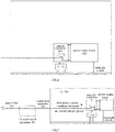
- Fig. 1a is a schematic diagram illustrating the connection between a TV main board and the other related components in the TV in some TV systems.
- the TV main board is integrated in the TV's rear casing.
- 220V power supply is input into the power supply board inside the TV via the power line.
- the power supply board converts a part of the power supply into DC power of 12V-which supplies power to the TV main board, and converts the other part into a light bar driving voltage for providing to the backlight light bar so as to lighten the screen.
- the TV main board outputs the processed multimedia signals to the subsequent components such as the timing controller (T-CON), which controls display on the screen.
- T-CON timing controller
- Fig. 1b is a rear view of a TV where a TV main board is integrated.
- the TV main board is integrated in the TV's rear casing. Since there are many external ports on the main board, the TV's rear casing has to allow many leading-out wires that connect to external devices (see Fig. 1b for instance), which negatively influences the appearance, and makes it hard to place and install the external devices in a convenient way. In addition, a TV main board of this kind cannot be detached and replaced with ease, so an entire TV may have to be replaced once its main board is destroyed or needs to be upgraded.
- One approach to solving the above problem includes placing the TV main board outside the TV casing as an independent apparatus. But the approach makes it necessary to provide both the TV and the main board with a respective power supply line and provide a line to connect the TV to the main board.
- the complicated wiring leads to further inconvenient use and installation, and the appearance is not concise and beautiful either.
- US2008/239229A1 discloses a liquid crystal display comprising a circuit board including a first connector which receives a data signal and a second connector which is separated from the first connector and receives a power supply voltage, a timing controller mounted on the circuit board, the timing controller receiving the power supply voltage from the second connector and the data signal from the first connector, and processing the data signal received from the first connector, and a liquid crystal panel displaying an image using the data signal processed by the timing controller.
- US2004/165119A1 discloses a TV receiving module and a display apparatus and a TV receiving system using the same, wherein the TV receiving module is small in size and is detachably mounted outside or inside of the display apparatus.
- the TV receiving module is adapted to select and receive a TV signal of a desired broadcast from among TV signal inputted from a TV broadcast receiving antenna or cable, and provide the received TV signal.
- a detachable connector unit includes a first connector installed in the TV receiving module for receiving external power and an external control signal and providing the TV signal received by the TV receiving module externally, and a second connector detachably coupled with the first connector.
- the display apparatus is connected to the TV receiving module via the second connector of the detachable connector unit to provide the external power and external control signal to the TV receiving module, receive the TV signal from the TV receiving module and output video and audio signals of the received TV signal.
- the display apparatus may be an LCD monitor or a PDP TV receiver.
- US2011/069055A1 discloses a display apparatus having a slim display body to display pictures.
- Main components such as a switching mode power supply and a main board, are disposed in a base unit, and a drive board mounted to a display module is connected to the switching mode power supply and the main board such that power is supplied to the display module and the main board transmits and receives a control signal
- the base unit serves as a stand to support the display body below the display body.
- the base unit is fixed to the rear of the connection unit to mount the display apparatus to a wall.
- a connection unit to connect the display body and the base unit is provided to change the position of the base unit.
- the connection unit is hingedly rotatable with respect to the display body and the base unit.
- US2011/317076A1 discloses an extension module connected between a TV set and signal sources so that the signal sources communicate media signals with the TV set, wherein the extension module comprises a first interface and a second interface, the first interface is electrically connected and communicates with the TV set, and the second interface is electrically connected with the signal sources and outputs a power supply signal and a control signal to the signal sources.
- the present disclosure provides a TV main board apparatus, a connection apparatus, a TV, and a TV system, which can be used and installed with more ease.
- a TV main board apparatus comprising: a casing having at least one opening; and a TV main board accommodated in the casing and having a first interface and a second interface that are exposed outside the casing via their respective openings, wherein, the first interface is capable of connecting to a power supply so as to receive first electric power, and the second interface is capable of connecting to a TV so as to transmit a multimedia signal and the first electric power to the TV and receive second electric power from the TV.
- the second electric power is converted from the first electric power by the TV and adapted for powering the TV main board apparatus.
- a terminal configured to transmit the first electric power, a terminal configured to transmit the second electric power, and a terminal configured to transmit the multimedia signal are integrated in the second interface.
- the second interface comprises a high definition multimedia interface (HDMI), and a part of pins of the HDMI are configured to transmit a high definition multimedia signal and another part of the pins are configured to transmit the second electric power.
- HDMI high definition multimedia interface
- the HDMI may have more than 19 pins.
- the second interface may have a live wire terminal and a neutral wire terminal that are configured to transmit the first electric power.
- a connection apparatus comprising: a connection line capable of transmitting a multimedia signal and first electric power that are supplied by a TV main board apparatus to a TV and transmitting second electric power that is supplied by the TV to the TV main board apparatus; a first connection section located at one end of the connection line and capable of connecting to the TV main board apparatus; and a second connection section located at the other end of the connection line and capable of connecting to the TV.
- the second electric power is converted from the first electric power by the TV and adapted for powering the TV main board apparatus.
- a terminal configured to transmit the first electric power, a terminal configured to transmit the second electric power, and a terminal configured to transmit the multimedia signal are integrated in the first connection section and the second connection section respectively.
- the first connection section and the second connection section respectively comprise a high definition multimedia interface (HDMI), and a part of pins of the HDMI are configured to transmit a high definition multimedia signal and another part of the pins are configured to transmit the second electric power.
- HDMI high definition multimedia interface
- the HDMI has more than 19 pins.
- the first connection section and the second connection section can respectively have a live wire terminal and a neutral wire terminal that are configured to transmit the first electric power.
- a TV comprising: a transfer apparatus configured to receive a multimedia signal from a TV main board apparatus so as to allow the multimedia signal to be played, and receive first electric power from the TV main board apparatus so as to supply the first electric power to a power supply board; and the power supply board configured to convert the first electric power into second electric power, supply the second electric power to the transfer apparatus so as to output the second electric power to the TV main board apparatus via the transfer apparatus, and convert the first electric power into third electric power for powering a backlight system of the TV.
- the power supply board is configured to convert the first electric power into fourth electric power for powering the transfer apparatus.
- the TV can further comprise a timing controller (T-CON), wherein the transfer apparatus supplies the multimedia signal to the T-CON.
- T-CON timing controller
- the transfer apparatus comprises an interface component in which a terminal configured to transmit the first electric power, a terminal configured to transmit the second electric power, and a terminal configured to transmit the multimedia signal are integrated.
- the interface component comprises a high definition multimedia interface (HDMI), and a part of the pins of the HDMI are configured to transmit a high definition multimedia signal and another part of the pins are configured to transmit the second electric power.
- HDMI high definition multimedia interface
- the HDMI may have more than 19 pins.
- the interface component can comprise a live wire terminal and a neutral wire terminal that are configured to transmit the first electric power.
- a TV system comprising a TV main board apparatus, a TV, one power line, and one connection apparatus, wherein the power line is capable of connecting the TV main board apparatus to a power supply so as to transmit first electric power to the TV main board apparatus from the power supply, and the connection apparatus is configured to connect the TV main board apparatus to the TV so as to transmit a multimedia signal and the first electric power to the TV from the TV main board apparatus and transmit second electric power to the TV main board apparatus from the TV.
- the TV main board apparatus can comprise: a casing having at least one opening; and a TV main board accommodated in the casing and having a first interface and a second interface that are exposed outside the casing via their respective openings, the first interface is connected to the power line, and the second interface is connected to the connection apparatus.
- a terminal configured to transmit the first electric power, a terminal configured to transmit the second electric power, and a terminal configured to transmit the multimedia signal are integrated in the second interface.
- the second interface comprises a high definition multimedia interface (HDMI), and a part of the pins of the HDMI are configured to transmit a high definition multimedia signal and another part of the pins are configured to transmit the second electric power.
- HDMI high definition multimedia interface
- the HDMI may have more than 19 pins.
- the second interface may have a live wire terminal and a neutral wire terminal that are configured to transmit the first electric power.
- connection apparatus can comprise: a connection line configured to transmit the multimedia signal and the first electric power that are supplied by the TV main board apparatus to the TV and transmit the second electric power that is supplied by the TV to the TV main board apparatus; a first connection section located at one end of the connection line and connected to the TV main board apparatus; and a second connection section located at the other end of the connection line and connected to the TV.
- a terminal configured to transmit the first electric power, a terminal configured to transmit the second electric power, and a terminal configured to transmit the multimedia signal are integrated in the first connection section and the second connection section respectively.
- the first connection section and the second connection section respectively comprise a high definition multimedia interface (HDMI), and a part of the pins of the HDMI are configured to transmit a high definition multimedia signal and another part of the pins are configured to transmit the second electric power.
- HDMI high definition multimedia interface
- the HDMI may have more than 19 pins.
- the first connection section and the second connection section respectively may have a live wire terminal and a neutral wire terminal that are configured to transmit the first electric power.
- the TV can comprise: a transfer apparatus configured to receive the multimedia signal from the TV main board apparatus so as to allow the multimedia signal to be played, and receive the first electric power from the TV main board apparatus to supply the first electric power to a power supply board; and the power supply board configured to convert the first electric power into the second electric power, supply the second electric power to the transfer apparatus so as to output the second electric power to the TV main board apparatus via the transfer apparatus for powering the TV main board apparatus, and convert the first electric power into third electric power for powering a backlight system of the TV.
- the power supply board is configured to convert the first electric power to fourth electric power for powering the transfer apparatus.
- the TV can further comprise a timing controller (T-CON), wherein the transfer apparatus supplies the multimedia signal to the T-CON.
- T-CON timing controller
- the transfer apparatus comprises an interface component connected to the connection apparatus and to the TV main board apparatus via the connection apparatus, and a terminal configured to transmit the first electric power, a terminal configured to transmit the second electric power, and a terminal configured to transmit the multimedia signal are integrated in the interface component.
- the interface component comprises a high definition multimedia interface (HDMI), and a part of pins of the HDMI are configured to transmit a high definition multimedia signal and another part of the pins are configured to transmit the second electric power.
- HDMI high definition multimedia interface
- the HDMI may have more than 19 pins.
- the interface component may have a live wire terminal and a neutral wire terminal that are configured to transmit the first electric power.
- Some embodiments may have one or more of the following advantages.
- the TV main board is separated as an independent apparatus from the TV, so the TV does not need to have a large number of leading-out wires, and the TV main board can be repaired and replaced with ease.
- merely connecting the TV to the TV main board apparatus and connecting the TV main board apparatus to a power supply makes it possible to supply power to both the TV main board apparatus and the TV and transmit a signal therebetween. As a result, the whole system becomes less complicated, easier to use and install, and concise and attractive in appearance.
- exemplary means "used as an instance or example, or explanatory".
- An "exemplary” example given here is not necessarily construed as being superior to or better than other examples.
- Fig. 2 is a schematic structural diagram showing a TV main board apparatus 200 according to an example of the present disclosure.
- the TV main board apparatus 200 comprises a casing 201 having at least one opening such as openings 2011, 2012.
- the TV main board apparatus 200 further comprises a TV main board 202 accommodated in the casing 201 and having a first interface 2021 and a second interface 2022.
- the first interface 2021 and the second interface 2022 are exposed outside the casing 201 via their respective openings 2011 and 2012.
- the first interface 2021 is connectable to a power supply so as to receive first electric power.
- the second interface 2022 is connectable to a TV so as to transmit a multimedia signal and the first electric power to the TV and receive second electric power from the TV.
- This example separates a TV main board as an independent apparatus from a TV, so the TV does not need to have a large number of leading-out wires, and the TV main board can be repaired and replaced with ease.
- the TV main board apparatus is capable of supplying the first electric power to the TV via the second interface so as to supply power to the TV and receiving the second electric power from the TV via the second interface so as to power itself. That way, only connecting the first interface to a power supply and connecting the second interface to the TV make it possible to supply power to both the TV main board apparatus and the TV and transmit a signal therebetween. As a result, the whole system becomes less complicated, easier to use and install, and concise and attractive in appearance.
- the casing 201 may be in any desired shape such as a cuboid or a cube.
- the present disclosure is not intended to place any restrictions on the shape of the casing.
- the opening primarily serves to expose an interface (e.g., a power supply interface, an audio/video interface, a cable television interface, or a USB interface) that is within the casing outside the casing, and accommodate various components such as press keys, a remote-control signal receiver, and a display.
- the use, shape, number, location and the like of the opening may be decided in light of actual needs, and are not restricted by the present disclosure.
- the opening 2011, which accommodates the first interface 2021, and the opening 2012, which accommodates the second interface 2022, may be located on the same side of the casing 201.
- the openings 2011 and 2012 may be located on other parts of the casing (e.g., two opposite sides of the casing). The present disclosure is not intended to place any restrictions on the location.
- the first interface 2021 is connectable to a power supply so as to receive the first electric power.
- the first electric power it may be AC power of 220V.
- the second interface 2022 is connectable to the TV so as to transmit the multimedia signal and the first electric power to the TV and receive the second electric power from the TV.
- the multimedia signal it may be a multimedia signal input externally or a multimedia signal that is converted by the TV main board from a built-in signal (e.g., an audio signal, a video signal and a text) of the TV main board apparatus.
- a multimedia signal may be, for instance, a high definition multimedia interface (HDMI) signal.
- HDMI high definition multimedia interface
- the second electric power may be obtained by converting the first electric power by the TV.
- it may be DC power obtained by performing an AC-DC conversion of AC power of 220V.
- the second electric power may serve to power the TV main board apparatus.
- the voltage of the second electric power may be set as the TV main board apparatus needs for power, such as 5V.
- a terminal configured to transmit the first electric power, a terminal configured to transmit the second electric power, and a terminal configured to transmit the multimedia signal may be integrated in the second interface 2022. Due to such integrated configuration, only one line is needed between the TV main board apparatus and the TV, making it possible to supply power to both the TV main board apparatus and the TV and transmit the multimedia signal therebetween. As a result, the whole system looks concise and attractive and is easy to use and install.
- the second interface may have an HDMI.
- the HDMI may have more than 19 pins, and for instance, preferably 29 or 30 pins. And a part of the pins (e.g., 13 pins, or any other number as needed) may serve to transmit an HDMI signal, and another part of the pins (e.g., 6 pins, or any other number as needed) may serve to transmit the second electric power (e.g., DC power of 5V). Some of the pins may serve to transmit a control signal or any other desired signal.
- the terminals of the second interface may be arranged in the form of an array of any profile in light of needs.
- the second interface 2022 may further have a live wire terminal and a neutral wire terminal that are configured to transmit the first electric power (e.g., power of the power supply of 220V).
- the first electric power e.g., power of the power supply of 220V.
- the shape of the HDMI, live wire terminal and neutral wire terminal, the location relationship between the HDMI and the live wire and neutral wire terminals, and the profile of the second interface may be decided by a person skilled in the art in light of actual needs.
- Figs. 3a-3d are schematic structural diagrams showing examples of the second interface 2022.
- the live wire terminal 302 and the neutral wire terminal 303 are respectively located besides the HDMI 301.
- the live wire terminal 302 and the neutral wire terminal 303 are located above and below the HDMI 301.
- the live wire terminal 302 and the neutral wire terminal 303 are located below (or above) the HDMI 301.
- either of the live wire terminal 302 and the neutral wire terminal 303 is located above (or below) the HDMI 301, and the other is located to the left (or right) of the HDMI 301.
- the live wire terminal 302 and the neutral wire terminal 303 may be both located to the left or right of the HDMI 301. It should be understood by a person skilled in the art that Figs. 3a-3d just give some examples of the second interface 2022 and its specific configuration may be devised by a person skilled in the art in light of actual needs, provided that it is capable of transmitting a multimedia signal and the first electric power to the TV and receiving the second electric power from the TV.
- Fig. 4 is a schematic structural diagram showing a connection apparatus according to an example of the present disclosure.
- the connection apparatus 400 comprises a connection line 401 capable of transmitting a multimedia signal and first electric power that are supplied by a TV main board apparatus to a TV and transmitting second electric power that is supplied by the TV to the TV main board apparatus.
- the connection apparatus 400 further comprises: a first connection section 402 located at one end of the connection line and connectable to the TV main board apparatus; and a second connection section 403 located at the other end of the connection line and connectable to the TV.
- connection apparatus exemplified as such integrates the transmission of a multimedia signal, the transmission of first electric power and the transmission of second electric power with each other.
- only one connection line makes it possible to supply power to both a TV and a TV main board apparatus and transmit a multimedia signal.
- the whole system becomes less complicated, easier to use and install, and concise and attractive in appearance.
- the first connection section 402 may be compatible with and connectable to the second interface 2022 of the TV main board apparatus in First Embodiment.
- a terminal configured to transmit the first electric power, a terminal configured to transmit the second electric power, and a terminal configured to transmit the multimedia signal may be integrated in the first connection section 402 and second connection section 403 respectively.
- the connection line 401 may comprise a connection line configured to transmit the first electric power, a connection line configured to transmit the second electric power, and a connection line configured to transmit the multimedia signal.
- Fig. 5 is a schematic structural diagram showing the cross section of an example of the connection line 401.
- the connection line may have: an HDMI transmission-line assembly 501 configured to transmit the multimedia signal and the second electric power; and a live wire 502 and a neutral wire 503 that are configured to transmit the first electric power.
- the live wire and neutral wire may be surrounded by a shielding section 504.
- Fig. 5 shows only one example of the connection line and its specific configuration may be devised by a person skilled in the art in light of actual needs, provided that it is capable of transmitting a multimedia signal, first electric power and second electric power.
- the first connection section 402 can be compatible with and connectable to the above-mentioned second interface.
- the first connection section 402 may have an HDMI with, for instance, more than 19 pins, and preferably 29 or 30 pins.
- a part of the pins e.g., 13 pins, or any other number as needed
- another part of the pins e.g., 6 pins, or any other number as needed
- the second electric power e.g., DC power of 5V.
- Some of the pins may serve to transmit a control signal or any other desired signal.
- the terminals of the first connection section 402 may be arranged in the form of an array of any profile.
- the first connection section 402 may further have a live wire terminal and a neutral wire terminal that are configured to transmit the first electric power (e.g., 220V power supply).
- the first electric power e.g., 220V power supply.
- the first connection section may be of configuration similar to that shown in Figs. 3a-3d , provide that it is compatible with and connectable to the corresponding interface of a TV main board apparatus.
- the second connection section 403 may be similar to the first connection section 402 in its design, or it may be devised by a person skilled in the art in light of actual needs.
- the second connection section 403 may be the same as or different from the first connection section 402 in configuration, provided that it is compatible with and connectable to the corresponding interface of a TV.
- Each of the transmission lines in the connection line 401 may correspond to and electrically connect to each of the terminals of the first connection section 402 and the second connection section 403.
- Fig. 6 is a schematic structural diagram showing a TV according to an example of the present disclosure.
- the TV comprises a transfer apparatus 601 that receives a multimedia signal from a TV main board apparatus so as to allow the multimedia signal to be played and receives first electric power from the TV main board apparatus so as to supply the first electric power to a power supply board 602.
- the TV further comprises the power supply board 602 that converts the first electric power into second electric power and supplies the second electric power to the transfer apparatus 601-which supplies the second electric power to the TV main board apparatus, and converts the first electric power into third electric power for powering a backlight system of the TV.
- the TV exemplified as such does not have a built-in TV main board.
- the TV main board apparatus is independent of the TV, so the TV does not need to have a large number of leading-out wires, and the TV main board can be repaired and replaced with ease.
- the transfer apparatus serves to supply power to both the TV and the TV main board apparatus and transmit a multimedia signal. That way, when the TV is to be used, it only needs to connect to the TV main board apparatus and does not need additional power lines. As a result, the whole system becomes less complicated, easier to use and install, and concise and attractive in appearance.
- the power supply board 602 may convert the first electric power into fourth electric power for powering the transfer apparatus.
- the fourth electric power may be obtained by performing an AC-DC conversion of AC power of 220V (the first electric power).
- the voltage of the fourth electric power may be set as the transfer apparatus needs for power, such as 12V.
- the power supply board 602 may include an AC-DC converter that converts the first electric power into the second or fourth electric power.
- the backlight system of the TV may be a light bar.
- the third electric power may be a driving voltage for the light bar.
- the voltage of the third electric power may be decided by a person skilled in the art in light of actual application scenarios.
- the TV may further comprise a timing controller (T-CON).
- T-CON timing controller
- the transfer apparatus may provide the T-CON with a multimedia signal (e.g., a video signal) so as to drive a display to display the multimedia signal.
- the transfer apparatus may comprise, for instance, a V-by-One (VBO, a signaling standard) interface, or a 51 Pin low voltage differential signaling (LVDS) interface, so as to supply a multimedia signal to the T-CON.
- VBO V-by-One
- LVDS 51 Pin low voltage differential signaling
- the transfer apparatus 601 may further comprise an interface component.
- the interface component can be compatible with and connectable to the second connection section 403 of the connection apparatus in Second Embodiment.
- a terminal configured to transmit the first electric power, a terminal configured to transmit the second electric power, and a terminal configured to transmit the multimedia signal may be integrated in the interface component.
- the interface component can be compatible with and connectable to the second connection section 403 of the above-mentioned connection apparatus.
- the end surface of the interface component may be of configuration similar to that shown in Figs. 3a-3d .
- the interface component may have an HDMI with more than 19 pins, and, for instance, preferably 29 or 30 pins.
- a part of the pins e.g., 13 pins, or any other number as needed
- another part of the pins e.g., 6 pins, or any other number as needed
- Some of the pins may serve to transmit a control signal or any other desired signal.
- the terminals of the interface component may be arranged in the form of an array of any profile.
- the interface component may have a live wire terminal and a neutral wire terminal that are configured to transmit the first electric power (e.g., 220V power supply).
- the first electric power e.g., 220V power supply.
- Figs. 3a-3d illustrate only examples of the configuration of the interface component and its configuration may be devised in light of actual needs, provided that it is integrated with a terminal configured to transmit the first electric power, a terminal configured to transmit the second electric power, and a terminal configured to transmit the multimedia signal.
- Fig. 7 is a schematic structural diagram showing a TV system according to an example of the present disclosure.
- the TV system comprises: a TV main board apparatus 701, a TV 703, one power line 704, and one connection apparatus 702.
- the power line 704 is capable of connecting the TV main board apparatus 701 to a power supply so as to transmit first electric power to the TV main board apparatus 701 from the power supply.
- the connection apparatus 702 is capable of connecting the TV main board apparatus 701 to the TV 703 so as to transmit a multimedia signal and the first electric power to the TV 703 from the TV main board apparatus 701 and transmit second electric power to the TV main board apparatus 701 from the TV 703.
- This example separates a TV main board as an independent apparatus from a TV, so the TV does not need to have a large number of leading-out wires, and the TV main board can be repaired and replaced with ease.
- it is unnecessary to provide the TV and the main board with separate power supply lines.
- connecting the TV main board apparatus to a power supply with one power line and connecting the TV to the TV main board apparatus with one connection apparatus make it possible to supply power to both the TV main board apparatus and the TV and transmit a signal therebetween.
- the whole system becomes less complicated, easier to use and install, and concise and attractive in appearance.
- the TV main board apparatus 701 may be of configuration similar to that of the TV main board apparatus in First Embodiment.
- the TV main board apparatus may comprise a casing having at least one opening; and a TV main board accommodated in the casing and having a first interface and a second interface exposed outside the casing via their respective openings.
- the first interface is connectable to the power line, and the second interface is connectable to the connection apparatus.
- a terminal configured to transmit the first electric power, a terminal configured to transmit the second electric power, and a terminal configured to transmit the multimedia signal may be integrated in the second interface.
- the second interface may have an HDMI.
- a part of the pins of the HDMI can be configured to transmit a high definition multimedia signal and another part of the pins can be configured to transmit the second electric power.
- the HDMI may have more than 19 pins.
- the second interface may have a live wire terminal and a neutral wire terminal that are configured to transmit the first electric power.
- connection apparatus 702 it may be of configuration similar to that of the connection apparatus in Second Embodiment.
- connection apparatus may comprise: a connection line capable of transmitting a multimedia signal and first electric power that are supplied by a TV main board apparatus to a TV and transmitting second electric power that is supplied by the TV to the TV main board apparatus; a first connection section located at one end of the connection line and connectable to the TV main board apparatus; and a second connection section located at the other end of the connection line and connectable to the TV.
- a terminal configured to transmit the first electric power, a terminal configured to transmit the second electric power, and a terminal configured to transmit the multimedia signal may be integrated in the first connection section and the second connection section respectively.
- the first connection section and the second connection section may respectively comprise an HDMI.
- a part of the pins of the HDMI can be configured to transmit a high definition multimedia signal and another part of the pins can be configured to transmit the second electric power.
- the HDMI may have more than 19 pins.
- the first connection section and the second connection section may respectively have a live wire terminal and a neutral wire terminal that are configured to transmit the first electric power.
- the TV 703 it may be of configuration similar to that of the TV in Third Embodiment.
- the TV 703 may comprise: a transfer apparatus that receives a multimedia signal from the TV main board apparatus so as to allow the multimedia signal to be played and receives first electric power from the TV main board apparatus so as to supply the first electric power to a power supply board; and the power supply board that converts the first electric power into second electric power, supplies the second electric power to the transfer apparatus so as to output the second electric power and thereby supply power to the TV main board apparatus via the transfer apparatus, and converts the first electric power into third electric power for powering a backlight system of the TV.
- the power supply board may convert the first electric power to fourth electric power for powering the transfer apparatus.
- the TV may further comprise a timing controller (T-CON), wherein the transfer apparatus supplies the multimedia signal to the T-CON.
- T-CON timing controller
- the transfer apparatus may comprise an interface component connectable to a connection apparatus and to a TV main board apparatus via the connection apparatus, wherein a terminal configured to transmit the first electric power, a terminal configured to transmit the second electric power, and a terminal configured to transmit the multimedia signal may be integrated in the interface component.
- the interface component may comprise a high definition multimedia interface (HDMI), wherein a part of the pins of the HDMI can be configured to transmit a high definition multimedia signal and another part of the pins can be configured to transmit the second electric power.
- HDMI may have more than 19 pins.
- the interface component may have a live wire terminal and a neutral wire terminal that are configured to transmit the first electric power.
- the power line 704 may be a power line selectable by a person skilled in the art which is capable of transmitting the first electric power (e.g., 220V AC power).
- the first interface of the TV main board apparatus 701 is connectable to a 220V AC power supply via the power line 704.
- 220V power (the first electric power) provided by the power supply can be supplied to the TV 703 by the TV main board apparatus 701 via the connection apparatus 702.
- the transfer apparatus in the TV 703 receives the 220V power and supplies it to the power supply board.
- the power supply board converts a part of the power into a driving voltage for the backlight bar, another part into 12V DC power as the fourth electric power for powering the transfer apparatus, and still another part into 5V DC power as the second electric power-which the transfer apparatus supplies to the TV main board apparatus 701 for powering the TV main board apparatus 701.
- the powered TV main board apparatus 701 supplies the converted HDMI signal to the TV 703 via the connection apparatus 702.
- the powered transfer apparatus can supply the HDMI signal to other components such as the T-CON so as to allow the multimedia signal to be played.
Landscapes
- Engineering & Computer Science (AREA)
- Multimedia (AREA)
- Signal Processing (AREA)
- Software Systems (AREA)
- Two-Way Televisions, Distribution Of Moving Picture Or The Like (AREA)
- Power Sources (AREA)
- Television Receiver Circuits (AREA)
- Structure Of Receivers (AREA)
Claims (10)
- TV-Hauptplatinenvorrichtung (200), umfassend:ein Gehäuse (201) mit mindestens einer Öffnung; undeine TV-Hauptplatine (202), die in dem Gehäuse (201) untergebracht ist und eine zweite Schnittstelle (2022) aufweist, die über eine Öffnung (2012) außerhalb des Gehäuses (201) freiliegt,wobei die zweite Schnittstelle (2022) dafür eingerichtet ist, sich mit einem Fernseher zu verbinden, um ein Multimediasignal an den Fernseher zu übertragen und eine zweite elektrische Leistung von dem Fernseher zu empfangen,die TV-Hauptplatinenvorrichtung (200) dadurch gekennzeichnet ist, dass:die TV-Hauptplatinenvorrichtung (200) als eine eigenständige Vorrichtung von dem Fernseher getrennt ist,wobei die TV-Hauptplatine (202) ferner eine erste Schnittstelle (2021) aufweist, die über eine Öffnung (2011) außerhalb des Gehäuses (201) freiliegt und dafür eingerichtet ist, sich mit einer Stromversorgung zu verbinden, um eine erste elektrische Leistung zu empfangen, unddie zweite Schnittstelle ferner dafür eingerichtet ist, die erste elektrische Leistung an den Fernseher zu übertragen.
- TV-Hauptplatinenvorrichtung (200) nach Anspruch 1, wobei die zweite elektrische Leistung von der ersten elektrischen Leistung durch den Fernseher umgewandelt und zum Betreiben der TV-Hauptplatinenvorrichtung (200) angepasst wird.
- TV-Hauptplatinenvorrichtung (200) nach Anspruch 1, wobei ein Anschluss zum Übertragen der ersten elektrischen Leistung, ein Anschluss zum Übertragen der zweiten elektrischen Leistung und ein Anschluss zum Übertragen des Multimedia-Signals in die zweite Schnittstelle (2022) integriert sind.
- TV-Hauptplatinenvorrichtung (200) nach Anspruch 1, wobei die zweite Schnittstelle (2022) eine hochauflösende Multimedia-Schnittstelle (HDMI) umfasst, und ein Teil von Pins des HDMI dafür eingerichtet ist, ein hochauflösendes Multimedia-Signal zu übertragen, und ein anderer Teil der Pins dafür eingerichtet ist, die zweite elektrische Leistung zu übertragen, wobei vorzugsweise die HDMI mehr als 19 Pins aufweist, und/oder
die zweite Schnittstelle (2022) einen Phasenleiteranschluss und einen Neutralleiteranschluss aufweist, die dafür eingerichtet sind, die erste elektrische Leistung zu übertragen. - Fernseher, umfassend:eine Übertragungsvorrichtung (601), die dafür eingerichtet ist, ein Multimediasignal von einer TV-Hauptplatinenvorrichtung zu empfangen, so dass das Multimediasignal abgespielt werden kann,wobei der Fernseher dadurch gekennzeichnet ist, dass:die TV-Hauptplatinenvorrichtung (200) als eine eigenständige Vorrichtung von dem Fernseher getrennt ist,die Übertragungsvorrichtung ferner dafür eingerichtet ist, eine erste elektrische Leistung von der TV-Hauptplatinenvorrichtung zu empfangen, um die erste elektrische Leistung der Stromversorgungsplatine (602) zuzuführen,wobei der Fernseher ferner die Stromversorgungsplatine (602) umfasst, die dafür eingerichtet ist, die erste elektrische Leistung in eine zweite elektrische Leistung umzuwandeln, die zweite elektrische Leistung der Übertragungsvorrichtung (601) zuzuführen um die zweite elektrische Leistung über die Übertragungsvorrichtung (601) an die TV-Hauptplatinenvorrichtung abzugeben, und die erste elektrische Leistung in eine dritte elektrische Leistung umzuwandeln, um ein Backlight-System des Fernsehers zu betreiben.
- Fernseher nach Anspruch 5, wobei die Stromversorgungsplatine (602) dafür eingerichtet ist, die erste elektrische Leistung in eine vierte elektrische Leistung zum Betreiben der Übertragungsvorrichtung (601) umzuwandeln.
- Fernseher nach Anspruch 5, ferner umfassend eine Zeitsteuereinrichtung T-CON, wobei die Übertragungsvorrichtung dafür eingerichtet ist, das Multimedia-Signal der T-CON zuzuführen.
- Fernseher nach Anspruch 5, wobei die Übertragungsvorrichtung (601) ferner eine Schnittstellenkomponente umfasst, in die ein Anschluss zum Übertragen der ersten elektrischen Leistung, ein Anschluss zum Übertragen der zweiten elektrischen Leistung und ein Anschluss zum Übertragen des Multimedia-Signals integriert sind.
- Fernseher nach Anspruch 8, wobei die Schnittstellekomponente eine hochauflösende Multimedia-Schnittstelle (HDMI) umfasst, und ein Teil der Pins der HDMI dafür eingerichtet ist, ein hochauflösendes Multimedia-Signal zu übertragen, und ein anderer Teil der Pins dafür eingerichtet ist, die zweite elektrische Leistung zu übertragen, wobei vorzugsweise die HDMI mehr als 19 Pins aufweist, und/oder
die Schnittstellenkomponente einen Phasenleiteranschluss und einen Neutralleiteranschluss umfasst, die dafür eingerichtet sind, die erste elektrische Leistung zu übertragen. - Fernsehsystem, umfassend eine TV-Hauptplatinenvorrichtung und einen Fernseher,
wobei das Fernsehsystem dadurch gekennzeichnet ist, dass
die TV-Hauptplatinenvorrichtung die TV-Hauptplatinenvorrichtung (701) nach einem der Ansprüche 1 bis 4 ist, und der Fernseher der Fernseher (703) nach einem der Ansprüche 5 bis 9 ist,
das Fernsehsystem ferner eine Stromleitung (704) und eine Verbindungsvorrichtung (702) umfasst,
wobei die Stromleitung (704) dafür eingerichtet ist, die erste Schnittstelle in der TV-Hauptplatinenvorrichtung (701) mit der Stromversorgung zu verbinden, um die erste elektrische Leistung an die TV-Hauptplatinenvorrichtung (701) von der Stromversorgung zu übertragen, wobei die Verbindungsvorrichtung (702) dafür eingerichtet ist, die TV-Hauptplatinenvorrichtung (701) mit dem Fernseher (703) zu verbinden, um das Multimedia-Signal und die erste elektrische Leistung an den Fernseher (703) von der TV-Hauptplatinenvorrichtung (702) zu übertragen und die zweite elektrische Leistung an die TV-Hauptplatinenvorrichtung (701) von dem Fernseher (703) zu übertragen, und
die Verbindungsvorrichtung (702) umfasst:eine Verbindungsleitung, die dafür eingerichtet ist, das Multimediasignal und die erste elektrische Leistung von der TV-Hauptplatinenvorrichtung an den Fernseher zu übertragen und die zweite elektrische Leistung von dem Fernseher an die TV-Hauptplatinenvorrichtung zu übertragen;einen ersten Verbindungsabschnitt, der sich an einem Ende der Verbindungsleitung befindet und dafür eingerichtet ist, sich mit der zweiten Schnittstelle in der TV-Hauptplatinenvorrichtung zu verbinden; undeinen zweiten Verbindungsabschnitt, der sich an dem anderen Ende der Verbindungsleitung befindet und dafür eingerichtet ist, sich mit der Übertragungsvorrichtung in dem Fernseher zu verbinden.
Applications Claiming Priority (2)
| Application Number | Priority Date | Filing Date | Title |
|---|---|---|---|
| CN201610127714.8A CN105721805B (zh) | 2016-03-07 | 2016-03-07 | 电视机主板装置、连接装置、电视机及电视机系统 |
| PCT/CN2016/098653 WO2017152606A1 (zh) | 2016-03-07 | 2016-09-12 | 电视机主板装置、连接装置、电视机及电视机系统 |
Publications (3)
| Publication Number | Publication Date |
|---|---|
| EP3343907A1 EP3343907A1 (de) | 2018-07-04 |
| EP3343907A4 EP3343907A4 (de) | 2018-11-21 |
| EP3343907B1 true EP3343907B1 (de) | 2019-11-27 |
Family
ID=56156427
Family Applications (1)
| Application Number | Title | Priority Date | Filing Date |
|---|---|---|---|
| EP16893251.5A Active EP3343907B1 (de) | 2016-03-07 | 2016-09-12 | Tv-hauptplatine, anschlussvorrichtung, tv und tv-system |
Country Status (6)
| Country | Link |
|---|---|
| US (1) | US20180255265A1 (de) |
| EP (1) | EP3343907B1 (de) |
| JP (1) | JP2019504581A (de) |
| KR (1) | KR20180077206A (de) |
| CN (1) | CN105721805B (de) |
| WO (1) | WO2017152606A1 (de) |
Families Citing this family (6)
| Publication number | Priority date | Publication date | Assignee | Title |
|---|---|---|---|---|
| CN105812692A (zh) * | 2016-03-07 | 2016-07-27 | 合智能科技(深圳)有限公司 | 电视机主板装置、电视机及电视机系统 |
| CN105721805B (zh) * | 2016-03-07 | 2019-05-14 | 合一智能科技(深圳)有限公司 | 电视机主板装置、连接装置、电视机及电视机系统 |
| CN105681706A (zh) * | 2016-03-07 | 2016-06-15 | 合一智能科技(深圳)有限公司 | 电视机主板装置及电视机系统 |
| CN110347418B (zh) * | 2019-06-28 | 2023-09-29 | 晶晨半导体(上海)股份有限公司 | 控制系统升级方法及控制系统 |
| CN110491304B (zh) * | 2019-09-20 | 2024-07-16 | 利亚德智慧显示(深圳)有限公司 | 插座及显示屏 |
| CN114510127A (zh) * | 2021-12-15 | 2022-05-17 | 北京云迹科技股份有限公司 | 一种兼容hdmi、mipi以及lvds接口的主板及机器人 |
Family Cites Families (25)
| Publication number | Priority date | Publication date | Assignee | Title |
|---|---|---|---|---|
| JP3259219B2 (ja) * | 1997-03-04 | 2002-02-25 | 住友電気工業株式会社 | 信号用ケーブル装置 |
| JP2000172184A (ja) * | 1998-12-02 | 2000-06-23 | Sony Corp | 表示装置 |
| JP2000184576A (ja) * | 1998-12-17 | 2000-06-30 | Matsushita Electric Ind Co Ltd | 雷サージ保護装置 |
| JP2001186423A (ja) * | 1999-12-27 | 2001-07-06 | Toshiba Corp | パーソナルコンピュータを用いたtv視聴、録画、再生装置及びpcカード電源供給方法並びにpcカード |
| JP3896103B2 (ja) * | 2002-12-16 | 2007-03-22 | 三星電機株式会社 | Tv受信モジュール及びディスプレー装置を利用したtv受信システム |
| JP3109615U (ja) * | 2004-12-28 | 2005-05-19 | 有限会社コイットソリューションズ | 広告画像再生装置 |
| KR100661364B1 (ko) * | 2005-05-26 | 2006-12-27 | 삼성전자주식회사 | 컴퓨터 시스템 및 디스플레이장치 |
| KR20080088854A (ko) * | 2007-03-30 | 2008-10-06 | 삼성전자주식회사 | 회로 기판 및 이를 포함하는 액정 표시 장치 |
| CN101068319A (zh) * | 2007-06-04 | 2007-11-07 | 北京派瑞根科技开发有限公司 | 可接收高清晰度电视信号的分体电视设计技术及其装置 |
| CN101753931A (zh) * | 2008-12-19 | 2010-06-23 | 康佳集团股份有限公司 | 一种超薄电视机 |
| CN101567987A (zh) * | 2009-05-31 | 2009-10-28 | 深圳创维-Rgb电子有限公司 | 一种平板电视机 |
| CN101902553A (zh) * | 2009-06-01 | 2010-12-01 | 海尔集团公司 | 扩展模块及具有该扩展模块的电视机 |
| KR101253565B1 (ko) * | 2009-09-22 | 2013-04-11 | 삼성전자주식회사 | 디스플레이 장치 |
| JP2012109990A (ja) * | 2011-12-20 | 2012-06-07 | Toshiba Corp | 電源供給回路 |
| KR101370352B1 (ko) * | 2011-12-27 | 2014-03-25 | 삼성전자주식회사 | 방송수신용 디스플레이장치 및 신호처리모듈, 방송수신장치 및 방송수신방법 |
| JP6143753B2 (ja) * | 2012-07-05 | 2017-06-07 | サターン ライセンシング エルエルシーSaturn Licensing LLC | ケーブルおよび電子機器 |
| CN102883199A (zh) * | 2012-09-29 | 2013-01-16 | 鸿富锦精密工业(深圳)有限公司 | 分体式电视及应用于所述分体式电视的控制盒 |
| JP6085945B2 (ja) * | 2012-10-29 | 2017-03-01 | コニカミノルタ株式会社 | 電源装置 |
| WO2014174941A1 (ja) * | 2013-04-26 | 2014-10-30 | ソニー株式会社 | コネクタ、データ送信装置、データ受信装置及びデータ送受信システム |
| CN103281183B (zh) * | 2013-04-27 | 2016-04-13 | 天地融科技股份有限公司 | 转换装置和显示系统 |
| CN103888698A (zh) * | 2014-02-25 | 2014-06-25 | 四川长虹电器股份有限公司 | 有线式分体结构电视机 |
| CN104767949A (zh) * | 2014-11-08 | 2015-07-08 | 晶晨半导体(上海)有限公司 | 分体式电视 |
| CN104768039A (zh) * | 2015-04-21 | 2015-07-08 | 福建捷联电子有限公司 | 显示系统与图像处理系统分离的tv及实现方法 |
| CN105681706A (zh) * | 2016-03-07 | 2016-06-15 | 合一智能科技(深圳)有限公司 | 电视机主板装置及电视机系统 |
| CN105721805B (zh) * | 2016-03-07 | 2019-05-14 | 合一智能科技(深圳)有限公司 | 电视机主板装置、连接装置、电视机及电视机系统 |
-
2016
- 2016-03-07 CN CN201610127714.8A patent/CN105721805B/zh active Active
- 2016-09-12 JP JP2018546729A patent/JP2019504581A/ja active Pending
- 2016-09-12 KR KR1020187014773A patent/KR20180077206A/ko not_active Ceased
- 2016-09-12 WO PCT/CN2016/098653 patent/WO2017152606A1/zh not_active Ceased
- 2016-09-12 EP EP16893251.5A patent/EP3343907B1/de active Active
- 2016-09-12 US US15/752,678 patent/US20180255265A1/en not_active Abandoned
Non-Patent Citations (1)
| Title |
|---|
| None * |
Also Published As
| Publication number | Publication date |
|---|---|
| WO2017152606A1 (zh) | 2017-09-14 |
| EP3343907A1 (de) | 2018-07-04 |
| CN105721805B (zh) | 2019-05-14 |
| US20180255265A1 (en) | 2018-09-06 |
| EP3343907A4 (de) | 2018-11-21 |
| JP2019504581A (ja) | 2019-02-14 |
| CN105721805A (zh) | 2016-06-29 |
| KR20180077206A (ko) | 2018-07-06 |
Similar Documents
| Publication | Publication Date | Title |
|---|---|---|
| JP3979300B2 (ja) | デジタルビデオ信号伝送用インターフェースモジュール | |
| EP3343907A1 (de) | Tv-hauptplatine, anschlussvorrichtung, tv und tv-system | |
| JP2022547820A (ja) | 表示装置に着脱自在に取り付け可能なドッキングステーションのためのシステム及び方法 | |
| US20090091838A1 (en) | Eyewear display and media device interconnection system | |
| US9071866B2 (en) | Wireless video/audio signal transmitter/receiver | |
| US20160131860A1 (en) | Fiber optic cable with electrical connectors at both ends, wall plates and control boxes | |
| US20170273202A1 (en) | Connector apparatus and display apparatus having the same | |
| CN105516629A (zh) | 显示屏及拼接屏 | |
| US20090153536A1 (en) | Receiving module and signal transmitting apparatus using the same | |
| CN102457686A (zh) | 多重显示装置及其方法 | |
| EP3285482A1 (de) | Hauptplatinenvorrichtung für fernseher und fernsehsystem | |
| CN105491421A (zh) | 一种基于Type-C接口的无电源线电视 | |
| EP3285483A1 (de) | Tv-hauptplatine, television und tv-system | |
| CN211154913U (zh) | 智能镜 | |
| CN104009355A (zh) | 多接口转接器 | |
| CN212084558U (zh) | Led显示面板及led显示屏的架构 | |
| KR101296815B1 (ko) | 디지털 방송용 디스플레이 보드 | |
| CN205140488U (zh) | 显示装置 | |
| CN205356608U (zh) | 用于智能led电视的控制设备 | |
| US20070139295A1 (en) | Extra-monitor control circuit system for monitor | |
| CN204681491U (zh) | 多格式影音转换器 | |
| KR102486470B1 (ko) | Dp 케이블을 이용한 모니터의 전원 및 신호 공급 장치 | |
| US20130215402A1 (en) | Modular projector | |
| US20070139296A1 (en) | Extra-monitor control circuit and transmission system for monitor | |
| GB2433616A (en) | Extra-monitor control circuit system for a monitor |
Legal Events
| Date | Code | Title | Description |
|---|---|---|---|
| STAA | Information on the status of an ep patent application or granted ep patent |
Free format text: STATUS: THE INTERNATIONAL PUBLICATION HAS BEEN MADE |
|
| PUAI | Public reference made under article 153(3) epc to a published international application that has entered the european phase |
Free format text: ORIGINAL CODE: 0009012 |
|
| STAA | Information on the status of an ep patent application or granted ep patent |
Free format text: STATUS: REQUEST FOR EXAMINATION WAS MADE |
|
| 17P | Request for examination filed |
Effective date: 20180326 |
|
| AK | Designated contracting states |
Kind code of ref document: A1 Designated state(s): AL AT BE BG CH CY CZ DE DK EE ES FI FR GB GR HR HU IE IS IT LI LT LU LV MC MK MT NL NO PL PT RO RS SE SI SK SM TR |
|
| AX | Request for extension of the european patent |
Extension state: BA ME |
|
| A4 | Supplementary search report drawn up and despatched |
Effective date: 20181022 |
|
| RIC1 | Information provided on ipc code assigned before grant |
Ipc: H04N 5/64 20060101AFI20181016BHEP Ipc: H04N 5/63 20060101ALI20181016BHEP Ipc: H04N 21/443 20110101ALI20181016BHEP |
|
| STAA | Information on the status of an ep patent application or granted ep patent |
Free format text: STATUS: EXAMINATION IS IN PROGRESS |
|
| 17Q | First examination report despatched |
Effective date: 20181130 |
|
| DAV | Request for validation of the european patent (deleted) | ||
| DAX | Request for extension of the european patent (deleted) | ||
| GRAP | Despatch of communication of intention to grant a patent |
Free format text: ORIGINAL CODE: EPIDOSNIGR1 |
|
| STAA | Information on the status of an ep patent application or granted ep patent |
Free format text: STATUS: GRANT OF PATENT IS INTENDED |
|
| INTG | Intention to grant announced |
Effective date: 20190717 |
|
| GRAS | Grant fee paid |
Free format text: ORIGINAL CODE: EPIDOSNIGR3 |
|
| GRAA | (expected) grant |
Free format text: ORIGINAL CODE: 0009210 |
|
| STAA | Information on the status of an ep patent application or granted ep patent |
Free format text: STATUS: THE PATENT HAS BEEN GRANTED |
|
| AK | Designated contracting states |
Kind code of ref document: B1 Designated state(s): AL AT BE BG CH CY CZ DE DK EE ES FI FR GB GR HR HU IE IS IT LI LT LU LV MC MK MT NL NO PL PT RO RS SE SI SK SM TR |
|
| REG | Reference to a national code |
Ref country code: GB Ref legal event code: FG4D |
|
| REG | Reference to a national code |
Ref country code: CH Ref legal event code: EP |
|
| REG | Reference to a national code |
Ref country code: AT Ref legal event code: REF Ref document number: 1208044 Country of ref document: AT Kind code of ref document: T Effective date: 20191215 |
|
| REG | Reference to a national code |
Ref country code: DE Ref legal event code: R096 Ref document number: 602016025327 Country of ref document: DE |
|
| REG | Reference to a national code |
Ref country code: IE Ref legal event code: FG4D |
|
| REG | Reference to a national code |
Ref country code: NL Ref legal event code: MP Effective date: 20191127 |
|
| REG | Reference to a national code |
Ref country code: LT Ref legal event code: MG4D |
|
| PG25 | Lapsed in a contracting state [announced via postgrant information from national office to epo] |
Ref country code: SE Free format text: LAPSE BECAUSE OF FAILURE TO SUBMIT A TRANSLATION OF THE DESCRIPTION OR TO PAY THE FEE WITHIN THE PRESCRIBED TIME-LIMIT Effective date: 20191127 Ref country code: LV Free format text: LAPSE BECAUSE OF FAILURE TO SUBMIT A TRANSLATION OF THE DESCRIPTION OR TO PAY THE FEE WITHIN THE PRESCRIBED TIME-LIMIT Effective date: 20191127 Ref country code: FI Free format text: LAPSE BECAUSE OF FAILURE TO SUBMIT A TRANSLATION OF THE DESCRIPTION OR TO PAY THE FEE WITHIN THE PRESCRIBED TIME-LIMIT Effective date: 20191127 Ref country code: BG Free format text: LAPSE BECAUSE OF FAILURE TO SUBMIT A TRANSLATION OF THE DESCRIPTION OR TO PAY THE FEE WITHIN THE PRESCRIBED TIME-LIMIT Effective date: 20200227 Ref country code: NO Free format text: LAPSE BECAUSE OF FAILURE TO SUBMIT A TRANSLATION OF THE DESCRIPTION OR TO PAY THE FEE WITHIN THE PRESCRIBED TIME-LIMIT Effective date: 20200227 Ref country code: GR Free format text: LAPSE BECAUSE OF FAILURE TO SUBMIT A TRANSLATION OF THE DESCRIPTION OR TO PAY THE FEE WITHIN THE PRESCRIBED TIME-LIMIT Effective date: 20200228 Ref country code: NL Free format text: LAPSE BECAUSE OF FAILURE TO SUBMIT A TRANSLATION OF THE DESCRIPTION OR TO PAY THE FEE WITHIN THE PRESCRIBED TIME-LIMIT Effective date: 20191127 Ref country code: LT Free format text: LAPSE BECAUSE OF FAILURE TO SUBMIT A TRANSLATION OF THE DESCRIPTION OR TO PAY THE FEE WITHIN THE PRESCRIBED TIME-LIMIT Effective date: 20191127 |
|
| PG25 | Lapsed in a contracting state [announced via postgrant information from national office to epo] |
Ref country code: HR Free format text: LAPSE BECAUSE OF FAILURE TO SUBMIT A TRANSLATION OF THE DESCRIPTION OR TO PAY THE FEE WITHIN THE PRESCRIBED TIME-LIMIT Effective date: 20191127 Ref country code: IS Free format text: LAPSE BECAUSE OF FAILURE TO SUBMIT A TRANSLATION OF THE DESCRIPTION OR TO PAY THE FEE WITHIN THE PRESCRIBED TIME-LIMIT Effective date: 20200327 Ref country code: RS Free format text: LAPSE BECAUSE OF FAILURE TO SUBMIT A TRANSLATION OF THE DESCRIPTION OR TO PAY THE FEE WITHIN THE PRESCRIBED TIME-LIMIT Effective date: 20191127 |
|
| PG25 | Lapsed in a contracting state [announced via postgrant information from national office to epo] |
Ref country code: AL Free format text: LAPSE BECAUSE OF FAILURE TO SUBMIT A TRANSLATION OF THE DESCRIPTION OR TO PAY THE FEE WITHIN THE PRESCRIBED TIME-LIMIT Effective date: 20191127 |
|
| PG25 | Lapsed in a contracting state [announced via postgrant information from national office to epo] |
Ref country code: PT Free format text: LAPSE BECAUSE OF FAILURE TO SUBMIT A TRANSLATION OF THE DESCRIPTION OR TO PAY THE FEE WITHIN THE PRESCRIBED TIME-LIMIT Effective date: 20200419 Ref country code: EE Free format text: LAPSE BECAUSE OF FAILURE TO SUBMIT A TRANSLATION OF THE DESCRIPTION OR TO PAY THE FEE WITHIN THE PRESCRIBED TIME-LIMIT Effective date: 20191127 Ref country code: RO Free format text: LAPSE BECAUSE OF FAILURE TO SUBMIT A TRANSLATION OF THE DESCRIPTION OR TO PAY THE FEE WITHIN THE PRESCRIBED TIME-LIMIT Effective date: 20191127 Ref country code: CZ Free format text: LAPSE BECAUSE OF FAILURE TO SUBMIT A TRANSLATION OF THE DESCRIPTION OR TO PAY THE FEE WITHIN THE PRESCRIBED TIME-LIMIT Effective date: 20191127 Ref country code: ES Free format text: LAPSE BECAUSE OF FAILURE TO SUBMIT A TRANSLATION OF THE DESCRIPTION OR TO PAY THE FEE WITHIN THE PRESCRIBED TIME-LIMIT Effective date: 20191127 Ref country code: DK Free format text: LAPSE BECAUSE OF FAILURE TO SUBMIT A TRANSLATION OF THE DESCRIPTION OR TO PAY THE FEE WITHIN THE PRESCRIBED TIME-LIMIT Effective date: 20191127 |
|
| REG | Reference to a national code |
Ref country code: DE Ref legal event code: R097 Ref document number: 602016025327 Country of ref document: DE |
|
| PG25 | Lapsed in a contracting state [announced via postgrant information from national office to epo] |
Ref country code: SM Free format text: LAPSE BECAUSE OF FAILURE TO SUBMIT A TRANSLATION OF THE DESCRIPTION OR TO PAY THE FEE WITHIN THE PRESCRIBED TIME-LIMIT Effective date: 20191127 Ref country code: SK Free format text: LAPSE BECAUSE OF FAILURE TO SUBMIT A TRANSLATION OF THE DESCRIPTION OR TO PAY THE FEE WITHIN THE PRESCRIBED TIME-LIMIT Effective date: 20191127 |
|
| REG | Reference to a national code |
Ref country code: AT Ref legal event code: MK05 Ref document number: 1208044 Country of ref document: AT Kind code of ref document: T Effective date: 20191127 |
|
| PLBE | No opposition filed within time limit |
Free format text: ORIGINAL CODE: 0009261 |
|
| STAA | Information on the status of an ep patent application or granted ep patent |
Free format text: STATUS: NO OPPOSITION FILED WITHIN TIME LIMIT |
|
| 26N | No opposition filed |
Effective date: 20200828 |
|
| PG25 | Lapsed in a contracting state [announced via postgrant information from national office to epo] |
Ref country code: SI Free format text: LAPSE BECAUSE OF FAILURE TO SUBMIT A TRANSLATION OF THE DESCRIPTION OR TO PAY THE FEE WITHIN THE PRESCRIBED TIME-LIMIT Effective date: 20191127 Ref country code: AT Free format text: LAPSE BECAUSE OF FAILURE TO SUBMIT A TRANSLATION OF THE DESCRIPTION OR TO PAY THE FEE WITHIN THE PRESCRIBED TIME-LIMIT Effective date: 20191127 Ref country code: PL Free format text: LAPSE BECAUSE OF FAILURE TO SUBMIT A TRANSLATION OF THE DESCRIPTION OR TO PAY THE FEE WITHIN THE PRESCRIBED TIME-LIMIT Effective date: 20191127 |
|
| PG25 | Lapsed in a contracting state [announced via postgrant information from national office to epo] |
Ref country code: IT Free format text: LAPSE BECAUSE OF FAILURE TO SUBMIT A TRANSLATION OF THE DESCRIPTION OR TO PAY THE FEE WITHIN THE PRESCRIBED TIME-LIMIT Effective date: 20191127 |
|
| REG | Reference to a national code |
Ref country code: DE Ref legal event code: R082 Ref document number: 602016025327 Country of ref document: DE Representative=s name: WEICKMANN & WEICKMANN PATENT- UND RECHTSANWAEL, DE Ref country code: DE Ref legal event code: R081 Ref document number: 602016025327 Country of ref document: DE Owner name: ALIBABA GROUP HOLDING LIMITED, GEORGE TOWN, KY Free format text: FORMER OWNER: HEYI INTELLIGENT TECHNOLOGY (SHENZHEN) CO., LTD., BEIJING, CN |
|
| REG | Reference to a national code |
Ref country code: CH Ref legal event code: PL |
|
| REG | Reference to a national code |
Ref country code: BE Ref legal event code: MM Effective date: 20200930 |
|
| PG25 | Lapsed in a contracting state [announced via postgrant information from national office to epo] |
Ref country code: LU Free format text: LAPSE BECAUSE OF NON-PAYMENT OF DUE FEES Effective date: 20200912 |
|
| PG25 | Lapsed in a contracting state [announced via postgrant information from national office to epo] |
Ref country code: CH Free format text: LAPSE BECAUSE OF NON-PAYMENT OF DUE FEES Effective date: 20200930 Ref country code: BE Free format text: LAPSE BECAUSE OF NON-PAYMENT OF DUE FEES Effective date: 20200930 Ref country code: IE Free format text: LAPSE BECAUSE OF NON-PAYMENT OF DUE FEES Effective date: 20200912 Ref country code: LI Free format text: LAPSE BECAUSE OF NON-PAYMENT OF DUE FEES Effective date: 20200930 |
|
| PG25 | Lapsed in a contracting state [announced via postgrant information from national office to epo] |
Ref country code: TR Free format text: LAPSE BECAUSE OF FAILURE TO SUBMIT A TRANSLATION OF THE DESCRIPTION OR TO PAY THE FEE WITHIN THE PRESCRIBED TIME-LIMIT Effective date: 20191127 Ref country code: MT Free format text: LAPSE BECAUSE OF FAILURE TO SUBMIT A TRANSLATION OF THE DESCRIPTION OR TO PAY THE FEE WITHIN THE PRESCRIBED TIME-LIMIT Effective date: 20191127 Ref country code: CY Free format text: LAPSE BECAUSE OF FAILURE TO SUBMIT A TRANSLATION OF THE DESCRIPTION OR TO PAY THE FEE WITHIN THE PRESCRIBED TIME-LIMIT Effective date: 20191127 |
|
| PG25 | Lapsed in a contracting state [announced via postgrant information from national office to epo] |
Ref country code: MK Free format text: LAPSE BECAUSE OF FAILURE TO SUBMIT A TRANSLATION OF THE DESCRIPTION OR TO PAY THE FEE WITHIN THE PRESCRIBED TIME-LIMIT Effective date: 20191127 Ref country code: MC Free format text: LAPSE BECAUSE OF FAILURE TO SUBMIT A TRANSLATION OF THE DESCRIPTION OR TO PAY THE FEE WITHIN THE PRESCRIBED TIME-LIMIT Effective date: 20191127 |
|
| P01 | Opt-out of the competence of the unified patent court (upc) registered |
Effective date: 20230418 |
|
| PGFP | Annual fee paid to national office [announced via postgrant information from national office to epo] |
Ref country code: DE Payment date: 20250923 Year of fee payment: 10 |
|
| PGFP | Annual fee paid to national office [announced via postgrant information from national office to epo] |
Ref country code: GB Payment date: 20250915 Year of fee payment: 10 |
|
| PGFP | Annual fee paid to national office [announced via postgrant information from national office to epo] |
Ref country code: FR Payment date: 20250915 Year of fee payment: 10 |