EP3344010A1 - Procédé de chauffage diélectrique à haute fréquence - Google Patents
Procédé de chauffage diélectrique à haute fréquence Download PDFInfo
- Publication number
- EP3344010A1 EP3344010A1 EP16841257.5A EP16841257A EP3344010A1 EP 3344010 A1 EP3344010 A1 EP 3344010A1 EP 16841257 A EP16841257 A EP 16841257A EP 3344010 A1 EP3344010 A1 EP 3344010A1
- Authority
- EP
- European Patent Office
- Prior art keywords
- heated
- objects
- sheet member
- frequency dielectric
- liquid
- Prior art date
- Legal status (The legal status is an assumption and is not a legal conclusion. Google has not performed a legal analysis and makes no representation as to the accuracy of the status listed.)
- Withdrawn
Links
Images

Classifications
-
- H—ELECTRICITY
- H05—ELECTRIC TECHNIQUES NOT OTHERWISE PROVIDED FOR
- H05B—ELECTRIC HEATING; ELECTRIC LIGHT SOURCES NOT OTHERWISE PROVIDED FOR; CIRCUIT ARRANGEMENTS FOR ELECTRIC LIGHT SOURCES, IN GENERAL
- H05B6/00—Heating by electric, magnetic or electromagnetic fields
- H05B6/46—Dielectric heating
- H05B6/62—Apparatus for specific applications
-
- H—ELECTRICITY
- H05—ELECTRIC TECHNIQUES NOT OTHERWISE PROVIDED FOR
- H05B—ELECTRIC HEATING; ELECTRIC LIGHT SOURCES NOT OTHERWISE PROVIDED FOR; CIRCUIT ARRANGEMENTS FOR ELECTRIC LIGHT SOURCES, IN GENERAL
- H05B6/00—Heating by electric, magnetic or electromagnetic fields
- H05B6/46—Dielectric heating
- H05B6/54—Electrodes
Definitions
- the present invention relates to a high-frequency dielectric heating method in which an object to be heated is disposed between opposing electrodes and is heated, and particularly relates to a high-frequency dielectric heating method suitable for quick thawing of frozen food.
- the applicant has proposed a technique in which an assembly of a plurality of pin electrodes including conductive pins is used as the electrode, the pin electrodes are made capable of moving independently of each other, the air gap is eliminated by causing the pin electrodes to come into contact with the surface of the frozen food to be heated so as to conform to the irregularities of the surface thereof, and it is thereby possible to suppress locally concentrated heating and thaw the frozen food evenly in a short time (see Patent Literature 1).
- Patent Literature 1 Japanese Patent Application Publication No. 2010-267401
- the object to be heated is thin as compared with an interval between the electrodes, there is a need for disposing a plurality of the objects to be heated so as to stack them in a direction in which the electrodes oppose each other and heating a large number of the objects to be heated in a short time.
- the object to be heated such as the frozen food
- the object to be heated such as the frozen food
- a drip occurs during the thawing.
- the drip flows out to the opposing surfaces of the objects to be heated that are disposed so as to be stacked, due to the high dielectric constant of water, a problem arises in that the dielectric constant changes according to a wet state of the object to be heated, and a local temperature rise becomes more conspicuous particularly at a portion where the drip collects.
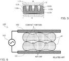
- a high-frequency dielectric heating device 100 when two frozen objects to be heated M are disposed so as to be directly stacked between a lower electrode 101 and an upper electrode 102 of a high-frequency dielectric heating device 100, and the objects to be heated M are heated and thawed by applying a high-frequency wave by a high-frequency power source 103, the opposing surfaces of the two objects to be heated have irregularities, and hence the contact portions and the air gaps are formed.
- impedance is high at a portion where the air gap is formed and a gap is large because the dielectric constant of air is low, and impedance is relatively low at the contact portion, and hence a current is concentrated on the contact portion.
- the contact portion exhibits thermal runaway, which leads to a reduction in quality such as the occurrence of discoloration or boiling.
- the current is reduced at portions other than the contact portion, and hence the thawing does not progress and the thawing becomes more uneven.
- portions other than the portion where the local temperature rise occurred were not thawed adequately, and the thawed state thereof was an extremely uneven thawed state.
- the temperature is locally increased to be significantly higher than a refrigeration temperature due to the local temperature rise, and hence the local temperature rise presents a problem in terms of quality preservation.
- composition change of protein or glucide and change such as melt of fat are caused by the local temperature rise, and hence a problem arises in that the high-frequency dielectric heating method cannot be used for food materials and foods that are served without being cooked, causes unevenness in cooking in the case where the food materials and the foods are cooked before being served, and adversely affects taste and texture.
- the present invention solves the above problems, and an object thereof is to provide the high-frequency dielectric heating method capable of, when a plurality of the objects to be heated are disposed in the direction in which the electrodes oppose each other, suppressing the local temperature rise on the opposing surfaces of the objects to be heated without reducing the heating speed, and heating the plurality of the objects to be heated in a short time.
- a high-frequency dielectric heating method is a high-frequency dielectric heating method in which an object to be heated is disposed between opposing electrodes and is heated, the method including: disposing a plurality of the objects to be heated in a direction in which the electrodes oppose each other; and heating the plurality of the objects to be heated in a state in which the plurality of the objects to be heated are spaced apart by a predetermined distance or more, whereby the above problems are solved.
- the high-frequency dielectric heating method of claim 1 it is possible to eliminate a contact portion between opposing surfaces of the opposing objects to be heated by heating the plurality of the objects to be heated in the state in which the plurality of the objects to be heated are spaced apart by the predetermined distance or more, and hence a difference in impedance that occurs depending on a location is reduced in the entire opposing surfaces, and concentration of a current is suppressed.
- a method for spacing the plurality of the objects to be heated apart by the predetermined distance or more includes a method in which partitions similar to fences are provided at intervals larger than the thickness of the object to be heated between the electrodes and the objects to be heated are arranged, and a method in which the objects to be heated are accommodated in box-like containers and the containers are stacked in the direction in which the electrodes oppose each other.
- the high-frequency dielectric heating method of claim 2 it is possible to eliminate the contact portion between the opposing surfaces of the opposing objects to be heated by heating the plurality of the objects to be heated in a state in which the plurality of the objects to be heated are spaced apart by the predetermined distance or more by interposing a sheet member between the plurality of the objects to be heated, and hence the difference in impedance that occurs depending on the location is reduced in the entire opposing surfaces, and the concentration of the current is suppressed.
- the sheet member has a layer having a void inside the layer, whereby the dielectric constant of the sheet member is reduced, and hence the difference in impedance that occurs depending on the location is reduced in the entire opposing surfaces even when the thin sheet member is used, the concentration of the current is suppressed, and it is possible to suppress the local temperature rise on the opposing surfaces of the objects to be heated.
- the sheet member has a liquid blocking function, whereby, even in the case where liquid such as a drip has occurred, an increase in dielectric constant caused by continuous presence of the liquid between the opposing surfaces of the objects to be heated is prevented, and it is possible to suppress the local temperature rise on the opposing surfaces of the objects to be heated further reliably.
- the sheet member has a liquid absorption function, whereby, even in the case where the liquid such as the drip has occurred, the liquid is kept from wetting the surface of the object to be heated and spreading or flowing into a concave portion and collecting, the increase in dielectric constant is prevented, and it is possible to suppress the local temperature rise on the opposing surfaces of the objects to be heated further reliably.
- the sheet member has at least a liquid absorption function layer and a liquid blocking function layer, whereby, when the liquid absorption function layer is positioned in an upper portion, the liquid such as the drip having flowed out from the upper object to be heated is absorbed and retained by the liquid absorption function layer, and the liquid blocking function layer does not allow the liquid to reach the surface of the lower object to be heated.
- the liquid is kept from wetting the surface of the object to be heated and spreading or flowing into the concave portion and collecting. Further, the liquid absorption function layer absorbs the liquid, the increase in dielectric constant caused by the continuous presence of the liquid between the opposing surfaces of the objects to be heated is thereby prevented, and it is possible to suppress the local temperature rise on the opposing surfaces of the objects to be heated reliably.
- the sheet member has a liquid passage function layer on a surface on a side of the liquid absorption function layer, whereby, when the liquid passage function layer is positioned in an upper portion, the liquid such as the drip having flowed out from the upper object to be heated passes through the liquid passage function layer and is absorbed and retained by the liquid absorption function layer, and the liquid blocking function layer does not allow the liquid to reach the surface of the lower object to be heated.
- the liquid is kept from collecting on each of the surfaces of both of the opposing objects to be heated, the increase in dielectric constant is prevented, and it is possible to suppress the local temperature rise on the opposing surfaces of the objects to be heated reliably.
- the liquid blocking function layer in the sheet member does not allow passage of liquid therethrough and has a cell inside the liquid blocking function layer, whereby it is possible to impart thermal insulation properties while maintaining the liquid blocking function.
- the sheet member has flexibility, whereby, even in the case where irregularities of the surface of the object to be heated are large, the sheet member conforms to the irregularities of the surface of the object to be heated, the objects to be heated are thereby kept from being spaced apart by a distance larger than the thickness of the sheet member as compared with the case where the opposing objects to be heated are directly stacked, and it is possible to prevent heating efficiency from deteriorating.
- the sheet member is also deformed correspondingly, and hence it is possible to maintain the same heating efficiency as that in the case where the opposing objects to be heated are directly stacked.
- the present invention is a high-frequency dielectric heating method in which an object to be heated is disposed between opposing electrodes and is heated
- the specific embodiment of the high-frequency dielectric heating method may be any embodiment as long as a plurality of the objects to be heated are disposed in a direction in which the electrodes oppose each other, and the plurality of the objects to be heated are heated in a state in which the plurality of the objects to be heated are spaced apart by a predetermined distance or more by interposing a sheet member between the plurality of the objects to be heated.
- the dielectric constant of each sheet member is as follows. polyethylene 2.3 foamed polyethylene 1.59 polypropylene nonwoven fabric 1.26 polyester nonwoven fabric 1.24 pulp fiber 1.63 nylon 2.6
- a high-frequency dielectric heating device 100 used in the high-frequency dielectric heating method according to one embodiment of the present invention is configured such that a conductive lower electrode 101 and a conductive upper electrode 102 are disposed so as to oppose each other, and an object to be heated M is disposed between the electrodes.
- a plurality of the objects to be heated M are disposed so as to be stacked in a direction in which the lower electrode 101 and the upper electrode 102 oppose each other with a sheet member 110 interposed between the plurality of the objects to be heated M, the lower electrode 101 and the upper electrode 102 are connected to a high-frequency power source 103, and the plurality of the objects to be heated M are simultaneously subjected to high-frequency dielectric heating.
- the above-described samples were disposed so as to be stacked in two layers with the sheet member 110 made of polyethylene having a low dielectric constant and a thickness of 0.5 mm or 0.2 mm that is interposed between the samples, the samples were subjected to high-frequency heating, and the surface temperatures of the opposing surfaces were observed.
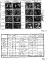
- Fig. 4 shows experiment conditions and results.
- the maximum temperature of the opposing surface of the object to be heated M is controlled to 40°C or less, and boiling caused by a local significant temperature rise does not occur.
- the chicken thigh meat is thawed to such a degree that pieces of the chicken thigh meat that stuck to each other in the pack when they were frozen can be separated by hand.
- the sheet member 110 is thicker, impedance is increased and a local temperature rise is reduced. However, heating efficiency is reduced, and hence the sheet member 110 is preferably thin moderately.
- Fig. 3 shows the surface temperatures of the opposing surfaces after the heating when the same samples as those described above were used and a material having voids was used as the sheet member 110.
- Fig. 4 shows the experiment conditions and the result.
- the dielectric constant is reduced with the presence of the voids in the sheet member 110, and an impedance difference with respect to an air gap can be further reduced.
- the maximum temperature of the opposing surface of the object to be heated M is controlled to 20°C or less, and the local significant temperature rise does not occur.
- the chicken thigh meat is thawed to such a degree that pieces of the chicken thigh meat that stuck to each other in the pack when they were frozen can be separated by hand.
- the sheet member 110 is made of polypropylene (PP) nonwoven fabric having voids, an adequate effect is obtained even when the thickness of the sheet member 110 is 0.1 mm.
- PP polypropylene
- the heating efficiency was reduced to such a degree that, in the thawed state under the above-described heating condition, pieces of the chicken thigh meat that stuck to each other in the pack when they were frozen could not be separated by hand.
- a thawing time from -15°C to 0°C in the internal temperature of the object to be heated M in the case of one pack of 2 kg of chicken thigh meat was 54 minutes, and the thawing time was 73 minutes in the case of two packs that were stacked in two layers in Reference Example 4.
- Maximum ice crystal formation zone (-5°C to -1°C) passage times in the case where two packs, four packs, and eight packs of chicken thigh meat, which are stacked in two layers, are heated and thawed under the conditions of Reference Example 4 are 63 minutes, 71 minutes, and 85 minutes, respectively, and can be represented approximately by the following expression.
- maximum ice crystal formation zone passage time 3.64 ⁇ the number of packs + 56 [minute]
- Example 1 an embodiment that uses a two-layered sheet member is used in Example 1.
- a liquid absorption function layer (pulp fiber) and a liquid blocking function layer (foamed PE) were used in this order from the side of the object to be heated M as the sheet member 110 and that the drip was caused to flow out by making a hole in a packaging material, and the surface temperatures were measured.
- Figs. 3 and 4 show evaluation results.
- the opposing surface maximum temperature is lower than that in Reference Example 5. This is because the liquid absorption function layer absorbs and diffuses the drip, and the drip is thereby prevented from flowing into a concave portion of the object to be heated M and collecting.
- Example 2 an embodiment that uses a three-layered sheet member is used in Example 2.
- the sheet member 110a is obtained by stacking polyester nonwoven fabric serving as the liquid passage function layer 111, pulp fiber serving as the liquid absorption function layer 112, and foamed polyethylene having a closed-cell structure that does not allow passage of liquid and serves as the liquid blocking function layer 113.
- Fig. 4 shows the experiment conditions and the result.
- the object to be heated M is frozen meat or the like
- the drip occurs during the thawing and, when the drip flows out to the opposing surfaces of the objects to be heated disposed so as to be stacked, the dielectric constant changes according to a wet state, and the local temperature rise becomes more conspicuous.
- the drip does not flow out because the pack is usually packaged, but the package is sometimes broken.
- a portion that becomes a contact portion when the objects to be heated M are disposed so as to be stacked is a convex portion, and hence it is highly possible that the package on the convex portion is broken.
- an effect of suppressing the local temperature rise is reduced when only the sheet member 110 of the embodiment described above is used.
- the maximum temperature of the opposing surface of the object to be heated M is controlled to 20°C or less, and the local significant temperature rise does not occur.
- the three layers of the liquid passage function layer, the liquid absorption function layer, and the liquid blocking function layer do not have to be layers made of physically different materials, but only need to be capable of sharing functions.
- a sheet member 110b made of a single material that is configured to function as a liquid passage function layer 111b, a liquid absorption function layer 112b, and a liquid blocking function layer 113b by providing a large number of convex portions 114 and concave portions 115 on one of the surfaces of the sheet member 110b such that a drip D having flowed out collects in the bottom portion of the concave portion 115.
- the objects to be heated M are stacked in two layers, but the objects to be heated M may also be stacked in three or more layers and the sheet members may be interposed between the opposing surfaces.
- the sheet member may also be interposed between the lower electrode 101 or the upper electrode 102 and the object to be heated M.
- the sheet member may be used as a packaging material, and the object to be heated M may be wrapped in the sheet member before being placed between the lower electrode 101 and the upper electrode 102.
- Three packs of 2 kg of frozen chicken having a pre-thawing temperature of -15°C were disposed as the objects to be heated between the electrodes in a state in which the packs are stacked in three layers, high-frequency thawing was performed for about 60 minutes with a frequency of 13.56 MHz and an output of 500 VA, and the surface temperature distribution of each of the opposing surfaces of the objects to be heated after the thawing was measured by thermography.
- the case where the sheet member made of polyethylene or nylon was disposed between the objects to be heated was compared with the case where the sheet member was not disposed.
- the area of one of the opposing surfaces of the objects to be heated M was assumed to be 100%, the ratio (hereinafter referred to as an area ratio) of the opposing surface having a surface temperature of not less than 40°C that influenced the quality in the surface temperature distribution of the opposing surface was calculated using a histogram output function of thermal image analysis software (FSV-S330 produced by Apiste Corporation), and the calculation result is shown in Fig. 4 .
- the area ratio of the opposing surface having a temperature of not less than 40°C was reduced by disposing the polyethylene sheet of Example 3-1.
- the area ratio exhibited a further reduction by disposing the nylon sheet having a high dielectric constant of Example 3-2.
- the high-frequency dielectric heating method of the present invention is capable of quickly heating the inside of the object to be heated M while suppressing the local temperature rise on the surface of the object to be heated M and suppressing degradation of quality or taste caused by the temperature rise on the surface of the object to be heated, can be widely applied to thawing of frozen food in restaurants and households and other industrial heating uses, and has high industrial applicability.
Landscapes
- Physics & Mathematics (AREA)
- Electromagnetism (AREA)
- Constitution Of High-Frequency Heating (AREA)
- Freezing, Cooling And Drying Of Foods (AREA)
Applications Claiming Priority (3)
| Application Number | Priority Date | Filing Date | Title |
|---|---|---|---|
| JP2015169430 | 2015-08-28 | ||
| JP2016033527A JP2017045714A (ja) | 2015-08-28 | 2016-02-24 | 高周波誘電加熱方法 |
| PCT/JP2016/068974 WO2017038225A1 (fr) | 2015-08-28 | 2016-06-27 | Procédé de chauffage diélectrique à haute fréquence |
Publications (2)
| Publication Number | Publication Date |
|---|---|
| EP3344010A1 true EP3344010A1 (fr) | 2018-07-04 |
| EP3344010A4 EP3344010A4 (fr) | 2019-05-01 |
Family
ID=58210423
Family Applications (1)
| Application Number | Title | Priority Date | Filing Date |
|---|---|---|---|
| EP16841257.5A Withdrawn EP3344010A4 (fr) | 2015-08-28 | 2016-06-27 | Procédé de chauffage diélectrique à haute fréquence |
Country Status (5)
| Country | Link |
|---|---|
| US (1) | US20180177003A1 (fr) |
| EP (1) | EP3344010A4 (fr) |
| JP (1) | JP2017045714A (fr) |
| KR (1) | KR20180048647A (fr) |
| CN (1) | CN107926089A (fr) |
Families Citing this family (4)
| Publication number | Priority date | Publication date | Assignee | Title |
|---|---|---|---|---|
| JP6861902B2 (ja) * | 2018-10-18 | 2021-04-21 | 三菱電機株式会社 | 誘電加熱装置 |
| JP7461263B2 (ja) * | 2020-09-29 | 2024-04-03 | シャープ株式会社 | 誘電加熱装置 |
| WO2023229195A1 (fr) * | 2022-05-27 | 2023-11-30 | 삼성전자 주식회사 | Dispositif de chauffage diélectrique |
| JP2026500965A (ja) * | 2023-01-11 | 2026-01-09 | ジェイティー インターナショナル エスエイ | エアロゾル生成システム |
Family Cites Families (48)
| Publication number | Priority date | Publication date | Assignee | Title |
|---|---|---|---|---|
| US2732472A (en) * | 1956-01-24 | ellsworth | ||
| US2732471A (en) * | 1956-01-24 | sweets | ||
| US2304958A (en) * | 1940-11-25 | 1942-12-15 | Rouy Auguste Louis Mar Antoine | Heating of dielectric materials |
| US2595502A (en) * | 1946-08-01 | 1952-05-06 | Allis Chalmers Mfg Co | Variable capacity circuit for dielectric heating apparatus |
| BE501223A (fr) * | 1950-02-14 | |||
| US2783344A (en) * | 1954-03-26 | 1957-02-26 | Nat Cylinder Gas Co | Dielectric heating systems and applicators |
| US2783349A (en) * | 1954-03-26 | 1957-02-26 | Nat Cylinder Gas Co | High-frequency heating applicators |
| US2783348A (en) * | 1954-03-26 | 1957-02-26 | Nat Cylinder Gas Co | High-frequency heating applicators |
| US2866063A (en) * | 1955-12-28 | 1958-12-23 | Magnetic Heating Corp | Drying of yarn by dielectric heating |
| US2870544A (en) * | 1956-01-24 | 1959-01-27 | Armstrong Cork Co | Method of drying fibrous boards |
| US2920172A (en) * | 1956-10-04 | 1960-01-05 | Gen Motors Corp | Dielectric heating and pressing die structure |
| US2991216A (en) * | 1957-03-26 | 1961-07-04 | Gen Motors Corp | Method for making and embossing decorative articles |
| US3892505A (en) * | 1968-07-23 | 1975-07-01 | Cebal Gp | Means for heating a mold |
| US3671709A (en) * | 1970-09-14 | 1972-06-20 | Monsanto Co | Heat sealing of porous materials |
| US4016025A (en) * | 1976-06-29 | 1977-04-05 | Peterson Everett A | Electronic sealing apparatus |
| GB1601713A (en) * | 1978-02-07 | 1981-11-04 | Electronic Kilns Luzern Gmbh | Drying lumber |
| US4308223A (en) * | 1980-03-24 | 1981-12-29 | Albany International Corp. | Method for producing electret fibers for enhancement of submicron aerosol filtration |
| US4380519A (en) * | 1981-03-30 | 1983-04-19 | E. I. Du Pont De Nemours And Company | Process for embossing polymeric substrates by using a composite structure of an aromatic polyamide fabric coated with a fluorosilicone rubber |
| JPS58138369A (ja) * | 1982-02-09 | 1983-08-17 | Matsushita Electric Ind Co Ltd | 高周波解凍方法 |
| US4836654A (en) * | 1986-06-30 | 1989-06-06 | Casio Computer Co., Ltd. | Drive method for a dual-frequency, dielectric anisotropy liquid crystal optical device |
| CH675097A5 (fr) * | 1988-03-28 | 1990-08-31 | De La Rue Giori Sa | |
| JP2795462B2 (ja) * | 1989-06-05 | 1998-09-10 | 鬼怒川ゴム工業株式会社 | 加硫ゴムの成形方法 |
| US5082436A (en) * | 1989-07-14 | 1992-01-21 | General Electric Company | Apparatus for deforming thermoplastic material using RF heating |
| US5139407A (en) * | 1989-09-01 | 1992-08-18 | General Electric Company | Apparatus for reducing thermoplastic material compression mold cycle time |
| JP3063769B2 (ja) * | 1990-07-17 | 2000-07-12 | イーシー化学株式会社 | 大気圧プラズマ表面処理法 |
| US5151568A (en) * | 1990-11-21 | 1992-09-29 | Rippley Martsey D | Disposable microwave cooking utensil |
| US5122043A (en) * | 1990-12-06 | 1992-06-16 | Matthews M Dean | Electric pulsed power vacuum press |
| US5223684A (en) * | 1991-05-06 | 1993-06-29 | Ford Motor Company | Method and apparatus for dielectrically heating an adhesive |
| US5427645A (en) * | 1991-12-09 | 1995-06-27 | W. R. Grace & Co.-Conn. | Apparatus and method for radio frequency sealing thermoplastic films together |
| US5686050A (en) * | 1992-10-09 | 1997-11-11 | The University Of Tennessee Research Corporation | Method and apparatus for the electrostatic charging of a web or film |
| US5266762A (en) * | 1992-11-04 | 1993-11-30 | Martin Marietta Energy Systems, Inc. | Method and apparatus for radio frequency ceramic sintering |
| FR2713666B1 (fr) * | 1993-12-15 | 1996-01-12 | Air Liquide | Procédé et dispositif de dépôt à basse température d'un film contenant du silicium sur un substrat métallique. |
| US5955174A (en) * | 1995-03-28 | 1999-09-21 | The University Of Tennessee Research Corporation | Composite of pleated and nonwoven webs |
| EP0801809A2 (fr) * | 1995-06-19 | 1997-10-22 | The University Of Tennessee Research Corporation | Procedes et electrodes de decharge pour la generation de plasmas sous pression d'une atmosphere et materiaux traites selon ces procedes |
| EP0885569B1 (fr) * | 1997-06-17 | 2002-09-04 | Yamamoto Vinita Co., Ltd. | Appareil de traitement à la chaleur d'aliments emballés |
| JP4177963B2 (ja) * | 1999-03-03 | 2008-11-05 | 山本ビニター株式会社 | 高周波解凍装置 |
| US6228438B1 (en) * | 1999-08-10 | 2001-05-08 | Unakis Balzers Aktiengesellschaft | Plasma reactor for the treatment of large size substrates |
| EP1162646A3 (fr) * | 2000-06-06 | 2004-10-13 | Matsushita Electric Works, Ltd. | Appareil et méthode de traitement par plasma |
| JP2002050465A (ja) * | 2000-08-02 | 2002-02-15 | Matsushita Electric Ind Co Ltd | 高周波解凍装置 |
| US6441554B1 (en) * | 2000-11-28 | 2002-08-27 | Se Plasma Inc. | Apparatus for generating low temperature plasma at atmospheric pressure |
| ATE410908T1 (de) * | 2005-08-08 | 2008-10-15 | Falmer Investment Ltd | Vorrichtung zum hochfrequenten trocknen von textilien |
| WO2009008421A1 (fr) * | 2007-07-10 | 2009-01-15 | Toyo Seikan Kaisha, Ltd. | Électrode de chauffage et procédé pour chauffer un matériau devant être chauffé en utilisant l'électrode de chauffage |
| US8770249B2 (en) * | 2007-10-18 | 2014-07-08 | Haemonetics Corporation | Tear seal moveable ground jaw for a tubing sealer |
| JP4402734B1 (ja) * | 2008-07-30 | 2010-01-20 | 株式会社日立エンジニアリング・アンド・サービス | 無接着剤アラミド−ポリフェニレンサルファイド積層体の製造方法、回転電機の絶縁部材及び絶縁構造 |
| WO2011061565A1 (fr) * | 2009-11-20 | 2011-05-26 | Danish Wood Technology Holding Aps | Procédé de traitement du bois |
| SE534837C2 (sv) * | 2010-05-21 | 2012-01-17 | Antrad Medical Ab | Metod och förfarande för att reducera lokala övervärmningar vid dielektrisk värmning av känsliga laster |
| NL2008879C2 (en) * | 2012-05-25 | 2013-11-26 | Top B V | Apparatus and process for heat treating a packaged food product. |
| JP2014158009A (ja) * | 2012-07-03 | 2014-08-28 | Hitachi High-Technologies Corp | 熱処理装置 |
-
2016
- 2016-02-24 JP JP2016033527A patent/JP2017045714A/ja active Pending
- 2016-06-27 CN CN201680046941.6A patent/CN107926089A/zh active Pending
- 2016-06-27 EP EP16841257.5A patent/EP3344010A4/fr not_active Withdrawn
- 2016-06-27 KR KR1020187005583A patent/KR20180048647A/ko not_active Withdrawn
-
2018
- 2018-02-13 US US15/895,298 patent/US20180177003A1/en not_active Abandoned
Also Published As
| Publication number | Publication date |
|---|---|
| CN107926089A (zh) | 2018-04-17 |
| US20180177003A1 (en) | 2018-06-21 |
| JP2017045714A (ja) | 2017-03-02 |
| EP3344010A4 (fr) | 2019-05-01 |
| KR20180048647A (ko) | 2018-05-10 |
Similar Documents
| Publication | Publication Date | Title |
|---|---|---|
| US20180177003A1 (en) | High-frequency dielectric heating method | |
| EP3185648B1 (fr) | Appareil et procédé de chauffage de produits alimentaires | |
| Wang et al. | Sterilization of foodstuffs using radio frequency heating | |
| Wang et al. | Radio-frequency heating of heterogeneous food–meat lasagna | |
| Tang et al. | Microwave heating in food processing | |
| US4015085A (en) | Container for the microwave heating of frozen sandwiches | |
| US10130114B2 (en) | Process for the deep-freezing of a substantially fluid food preparation | |
| SE1000546A1 (sv) | Metod och förfarande för att reducera lokala övervärmningar vid dielektrisk värmning av känsliga laster | |
| WO2019011467A1 (fr) | Procédé de scellement de composantes de menus partiellement préparées, et machine à sceller | |
| JP6593034B2 (ja) | 高周波誘電加熱用シート部材 | |
| Cin et al. | In-pack radio frequency heating of liquid whole egg: Effect of agitation on heating rate and uniformity | |
| WO2017038225A1 (fr) | Procédé de chauffage diélectrique à haute fréquence | |
| CN101297712B (zh) | 液态物料低温电场杀菌方法 | |
| Tang et al. | Microwave and radio frequency in sterilization and pasteurization applications | |
| US20170196245A1 (en) | Apparatus and method for heating a food product constituted of a sandwich or the like, before it is consumed | |
| WO1993008705A1 (fr) | Decongelation d'aliments congeles | |
| EP2471381B1 (fr) | Procédé et usine pour la fabrication de couches de légumes et les produits obtenus à partir de celles-ci | |
| US20210068213A1 (en) | Radio frequency and convection processing apparatus and method | |
| US2453130A (en) | Freezing high liquid content fruits and vegetables | |
| US20200390129A1 (en) | Radio frequency and impingement processing apparatus and method | |
| Orsat et al. | Electrical conductivity effect on dielectric properties and radio-frequency heating | |
| CN101686730B (zh) | 原料片的冷冻方法、原料片的输送或保存方法、原料片的加工方法、及原料片冷冻物 | |
| KR20170046889A (ko) | 전자기파 가열 급속동결 장치 및 방법 | |
| DE102017006670A1 (de) | Transportbox insbesondere für teilzubereitete Speisen | |
| LIND et al. | THAWING OF FOOD IN CATERING 1 |
Legal Events
| Date | Code | Title | Description |
|---|---|---|---|
| STAA | Information on the status of an ep patent application or granted ep patent |
Free format text: STATUS: THE INTERNATIONAL PUBLICATION HAS BEEN MADE |
|
| PUAI | Public reference made under article 153(3) epc to a published international application that has entered the european phase |
Free format text: ORIGINAL CODE: 0009012 |
|
| STAA | Information on the status of an ep patent application or granted ep patent |
Free format text: STATUS: REQUEST FOR EXAMINATION WAS MADE |
|
| 17P | Request for examination filed |
Effective date: 20180223 |
|
| AK | Designated contracting states |
Kind code of ref document: A1 Designated state(s): AL AT BE BG CH CY CZ DE DK EE ES FI FR GB GR HR HU IE IS IT LI LT LU LV MC MK MT NL NO PL PT RO RS SE SI SK SM TR |
|
| AX | Request for extension of the european patent |
Extension state: BA ME |
|
| DAV | Request for validation of the european patent (deleted) | ||
| DAX | Request for extension of the european patent (deleted) | ||
| RIN1 | Information on inventor provided before grant (corrected) |
Inventor name: MARUYAMA, TOMOKI Inventor name: YAMADA, SHINJI |
|
| A4 | Supplementary search report drawn up and despatched |
Effective date: 20190402 |
|
| RIC1 | Information provided on ipc code assigned before grant |
Ipc: H05B 6/54 20060101AFI20190327BHEP |
|
| STAA | Information on the status of an ep patent application or granted ep patent |
Free format text: STATUS: THE APPLICATION IS DEEMED TO BE WITHDRAWN |
|
| 18D | Application deemed to be withdrawn |
Effective date: 20191105 |