EP3344193B1 - Prothèse pour remplacer une articulation dans une main ou un pied humain - Google Patents
Prothèse pour remplacer une articulation dans une main ou un pied humain Download PDFInfo
- Publication number
- EP3344193B1 EP3344193B1 EP16840959.7A EP16840959A EP3344193B1 EP 3344193 B1 EP3344193 B1 EP 3344193B1 EP 16840959 A EP16840959 A EP 16840959A EP 3344193 B1 EP3344193 B1 EP 3344193B1
- Authority
- EP
- European Patent Office
- Prior art keywords
- prosthesis
- bone
- helical spring
- flange
- joint
- Prior art date
- Legal status (The legal status is an assumption and is not a legal conclusion. Google has not performed a legal analysis and makes no representation as to the accuracy of the status listed.)
- Not-in-force
Links
Images





Classifications
-
- A—HUMAN NECESSITIES
- A61—MEDICAL OR VETERINARY SCIENCE; HYGIENE
- A61F—FILTERS IMPLANTABLE INTO BLOOD VESSELS; PROSTHESES; DEVICES PROVIDING PATENCY TO, OR PREVENTING COLLAPSING OF, TUBULAR STRUCTURES OF THE BODY, e.g. STENTS; ORTHOPAEDIC, NURSING OR CONTRACEPTIVE DEVICES; FOMENTATION; TREATMENT OR PROTECTION OF EYES OR EARS; BANDAGES, DRESSINGS OR ABSORBENT PADS; FIRST-AID KITS
- A61F2/00—Filters implantable into blood vessels; Prostheses, i.e. artificial substitutes or replacements for parts of the body; Appliances for connecting them with the body; Devices providing patency to, or preventing collapsing of, tubular structures of the body, e.g. stents
- A61F2/02—Prostheses implantable into the body
- A61F2/30—Joints
- A61F2/42—Joints for wrists or ankles; for hands, e.g. fingers; for feet, e.g. toes
- A61F2/4241—Joints for wrists or ankles; for hands, e.g. fingers; for feet, e.g. toes for hands, e.g. fingers
-
- A—HUMAN NECESSITIES
- A61—MEDICAL OR VETERINARY SCIENCE; HYGIENE
- A61F—FILTERS IMPLANTABLE INTO BLOOD VESSELS; PROSTHESES; DEVICES PROVIDING PATENCY TO, OR PREVENTING COLLAPSING OF, TUBULAR STRUCTURES OF THE BODY, e.g. STENTS; ORTHOPAEDIC, NURSING OR CONTRACEPTIVE DEVICES; FOMENTATION; TREATMENT OR PROTECTION OF EYES OR EARS; BANDAGES, DRESSINGS OR ABSORBENT PADS; FIRST-AID KITS
- A61F2/00—Filters implantable into blood vessels; Prostheses, i.e. artificial substitutes or replacements for parts of the body; Appliances for connecting them with the body; Devices providing patency to, or preventing collapsing of, tubular structures of the body, e.g. stents
- A61F2/02—Prostheses implantable into the body
- A61F2/30—Joints
- A61F2/42—Joints for wrists or ankles; for hands, e.g. fingers; for feet, e.g. toes
- A61F2/4225—Joints for wrists or ankles; for hands, e.g. fingers; for feet, e.g. toes for feet, e.g. toes
-
- A—HUMAN NECESSITIES
- A61—MEDICAL OR VETERINARY SCIENCE; HYGIENE
- A61F—FILTERS IMPLANTABLE INTO BLOOD VESSELS; PROSTHESES; DEVICES PROVIDING PATENCY TO, OR PREVENTING COLLAPSING OF, TUBULAR STRUCTURES OF THE BODY, e.g. STENTS; ORTHOPAEDIC, NURSING OR CONTRACEPTIVE DEVICES; FOMENTATION; TREATMENT OR PROTECTION OF EYES OR EARS; BANDAGES, DRESSINGS OR ABSORBENT PADS; FIRST-AID KITS
- A61F2/00—Filters implantable into blood vessels; Prostheses, i.e. artificial substitutes or replacements for parts of the body; Appliances for connecting them with the body; Devices providing patency to, or preventing collapsing of, tubular structures of the body, e.g. stents
- A61F2/02—Prostheses implantable into the body
- A61F2/30—Joints
- A61F2002/30001—Additional features of subject-matter classified in A61F2/28, A61F2/30 and subgroups thereof
- A61F2002/30316—The prosthesis having different structural features at different locations within the same prosthesis; Connections between prosthetic parts; Special structural features of bone or joint prostheses not otherwise provided for
- A61F2002/30329—Connections or couplings between prosthetic parts, e.g. between modular parts; Connecting elements
- A61F2002/30462—Connections or couplings between prosthetic parts, e.g. between modular parts; Connecting elements retained or tied with a rope, string, thread, wire or cable
-
- A—HUMAN NECESSITIES
- A61—MEDICAL OR VETERINARY SCIENCE; HYGIENE
- A61F—FILTERS IMPLANTABLE INTO BLOOD VESSELS; PROSTHESES; DEVICES PROVIDING PATENCY TO, OR PREVENTING COLLAPSING OF, TUBULAR STRUCTURES OF THE BODY, e.g. STENTS; ORTHOPAEDIC, NURSING OR CONTRACEPTIVE DEVICES; FOMENTATION; TREATMENT OR PROTECTION OF EYES OR EARS; BANDAGES, DRESSINGS OR ABSORBENT PADS; FIRST-AID KITS
- A61F2/00—Filters implantable into blood vessels; Prostheses, i.e. artificial substitutes or replacements for parts of the body; Appliances for connecting them with the body; Devices providing patency to, or preventing collapsing of, tubular structures of the body, e.g. stents
- A61F2/02—Prostheses implantable into the body
- A61F2/30—Joints
- A61F2002/30001—Additional features of subject-matter classified in A61F2/28, A61F2/30 and subgroups thereof
- A61F2002/30316—The prosthesis having different structural features at different locations within the same prosthesis; Connections between prosthetic parts; Special structural features of bone or joint prostheses not otherwise provided for
- A61F2002/30329—Connections or couplings between prosthetic parts, e.g. between modular parts; Connecting elements
- A61F2002/30476—Connections or couplings between prosthetic parts, e.g. between modular parts; Connecting elements locked by an additional locking mechanism
- A61F2002/30507—Connections or couplings between prosthetic parts, e.g. between modular parts; Connecting elements locked by an additional locking mechanism using a threaded locking member, e.g. a locking screw or a set screw
-
- A—HUMAN NECESSITIES
- A61—MEDICAL OR VETERINARY SCIENCE; HYGIENE
- A61F—FILTERS IMPLANTABLE INTO BLOOD VESSELS; PROSTHESES; DEVICES PROVIDING PATENCY TO, OR PREVENTING COLLAPSING OF, TUBULAR STRUCTURES OF THE BODY, e.g. STENTS; ORTHOPAEDIC, NURSING OR CONTRACEPTIVE DEVICES; FOMENTATION; TREATMENT OR PROTECTION OF EYES OR EARS; BANDAGES, DRESSINGS OR ABSORBENT PADS; FIRST-AID KITS
- A61F2/00—Filters implantable into blood vessels; Prostheses, i.e. artificial substitutes or replacements for parts of the body; Appliances for connecting them with the body; Devices providing patency to, or preventing collapsing of, tubular structures of the body, e.g. stents
- A61F2/02—Prostheses implantable into the body
- A61F2/30—Joints
- A61F2002/30001—Additional features of subject-matter classified in A61F2/28, A61F2/30 and subgroups thereof
- A61F2002/30316—The prosthesis having different structural features at different locations within the same prosthesis; Connections between prosthetic parts; Special structural features of bone or joint prostheses not otherwise provided for
- A61F2002/30535—Special structural features of bone or joint prostheses not otherwise provided for
- A61F2002/30565—Special structural features of bone or joint prostheses not otherwise provided for having spring elements
- A61F2002/30566—Helical springs
-
- A—HUMAN NECESSITIES
- A61—MEDICAL OR VETERINARY SCIENCE; HYGIENE
- A61F—FILTERS IMPLANTABLE INTO BLOOD VESSELS; PROSTHESES; DEVICES PROVIDING PATENCY TO, OR PREVENTING COLLAPSING OF, TUBULAR STRUCTURES OF THE BODY, e.g. STENTS; ORTHOPAEDIC, NURSING OR CONTRACEPTIVE DEVICES; FOMENTATION; TREATMENT OR PROTECTION OF EYES OR EARS; BANDAGES, DRESSINGS OR ABSORBENT PADS; FIRST-AID KITS
- A61F2/00—Filters implantable into blood vessels; Prostheses, i.e. artificial substitutes or replacements for parts of the body; Appliances for connecting them with the body; Devices providing patency to, or preventing collapsing of, tubular structures of the body, e.g. stents
- A61F2/02—Prostheses implantable into the body
- A61F2/30—Joints
- A61F2002/30001—Additional features of subject-matter classified in A61F2/28, A61F2/30 and subgroups thereof
- A61F2002/30316—The prosthesis having different structural features at different locations within the same prosthesis; Connections between prosthetic parts; Special structural features of bone or joint prostheses not otherwise provided for
- A61F2002/30535—Special structural features of bone or joint prostheses not otherwise provided for
- A61F2002/30565—Special structural features of bone or joint prostheses not otherwise provided for having spring elements
- A61F2002/30571—Leaf springs
-
- A—HUMAN NECESSITIES
- A61—MEDICAL OR VETERINARY SCIENCE; HYGIENE
- A61F—FILTERS IMPLANTABLE INTO BLOOD VESSELS; PROSTHESES; DEVICES PROVIDING PATENCY TO, OR PREVENTING COLLAPSING OF, TUBULAR STRUCTURES OF THE BODY, e.g. STENTS; ORTHOPAEDIC, NURSING OR CONTRACEPTIVE DEVICES; FOMENTATION; TREATMENT OR PROTECTION OF EYES OR EARS; BANDAGES, DRESSINGS OR ABSORBENT PADS; FIRST-AID KITS
- A61F2/00—Filters implantable into blood vessels; Prostheses, i.e. artificial substitutes or replacements for parts of the body; Appliances for connecting them with the body; Devices providing patency to, or preventing collapsing of, tubular structures of the body, e.g. stents
- A61F2/02—Prostheses implantable into the body
- A61F2/30—Joints
- A61F2/30767—Special external or bone-contacting surface, e.g. coating for improving bone ingrowth
- A61F2/30771—Special external or bone-contacting surface, e.g. coating for improving bone ingrowth applied in original prostheses, e.g. holes or grooves
- A61F2002/3085—Special external or bone-contacting surface, e.g. coating for improving bone ingrowth applied in original prostheses, e.g. holes or grooves with a threaded, e.g. self-tapping, bone-engaging surface, e.g. external surface
-
- A—HUMAN NECESSITIES
- A61—MEDICAL OR VETERINARY SCIENCE; HYGIENE
- A61F—FILTERS IMPLANTABLE INTO BLOOD VESSELS; PROSTHESES; DEVICES PROVIDING PATENCY TO, OR PREVENTING COLLAPSING OF, TUBULAR STRUCTURES OF THE BODY, e.g. STENTS; ORTHOPAEDIC, NURSING OR CONTRACEPTIVE DEVICES; FOMENTATION; TREATMENT OR PROTECTION OF EYES OR EARS; BANDAGES, DRESSINGS OR ABSORBENT PADS; FIRST-AID KITS
- A61F2/00—Filters implantable into blood vessels; Prostheses, i.e. artificial substitutes or replacements for parts of the body; Appliances for connecting them with the body; Devices providing patency to, or preventing collapsing of, tubular structures of the body, e.g. stents
- A61F2/02—Prostheses implantable into the body
- A61F2/30—Joints
- A61F2/42—Joints for wrists or ankles; for hands, e.g. fingers; for feet, e.g. toes
- A61F2/4241—Joints for wrists or ankles; for hands, e.g. fingers; for feet, e.g. toes for hands, e.g. fingers
- A61F2002/4256—Joints for wrists or ankles; for hands, e.g. fingers; for feet, e.g. toes for hands, e.g. fingers for carpo-metacarpal joints, i.e. CMC joints
- A61F2002/4258—Joints for wrists or ankles; for hands, e.g. fingers; for feet, e.g. toes for hands, e.g. fingers for carpo-metacarpal joints, i.e. CMC joints for trapezo-metacarpal joints of thumbs
-
- A—HUMAN NECESSITIES
- A61—MEDICAL OR VETERINARY SCIENCE; HYGIENE
- A61F—FILTERS IMPLANTABLE INTO BLOOD VESSELS; PROSTHESES; DEVICES PROVIDING PATENCY TO, OR PREVENTING COLLAPSING OF, TUBULAR STRUCTURES OF THE BODY, e.g. STENTS; ORTHOPAEDIC, NURSING OR CONTRACEPTIVE DEVICES; FOMENTATION; TREATMENT OR PROTECTION OF EYES OR EARS; BANDAGES, DRESSINGS OR ABSORBENT PADS; FIRST-AID KITS
- A61F2/00—Filters implantable into blood vessels; Prostheses, i.e. artificial substitutes or replacements for parts of the body; Appliances for connecting them with the body; Devices providing patency to, or preventing collapsing of, tubular structures of the body, e.g. stents
- A61F2/02—Prostheses implantable into the body
- A61F2/30—Joints
- A61F2/42—Joints for wrists or ankles; for hands, e.g. fingers; for feet, e.g. toes
- A61F2/4261—Joints for wrists or ankles; for hands, e.g. fingers; for feet, e.g. toes for wrists
- A61F2002/4271—Carpal bones
- A61F2002/4274—Distal carpal row, i.e. bones adjacent the metacarpal bones
- A61F2002/4279—Trapezoid
Definitions
- the present invention relates to medical prostheses and, in particular, it concerns a prosthesis for replacing a joint between a first bone and a second bone in a human hand or foot.
- the first elongated bone (metacarpal) at the base of the thumb is connected to the wrist trapezium through the carpometacarpal (CMC) joint which is sometimes referred to as the trapezio-metacarpal joint.
- CMC carpometacarpal
- Osteoarthritis, rheumatoid arthritis, and post-traumatic arthritis of the carpometacarpal (CMC) joint cause interminable pain and poor function of the thumb. Patients who have mild symptoms often respond to rest, immobilization, non-steroidal anti-inflammatory drugs, or intra-articular injections of steroids. However, patients who have more severe forms of trapezio-metacarpal (carpometacarpal) arthritis may have dorsoradial subluxation of the joint, adduction contracture of the first web space, severe loss of articular cartilage, secondary metacarpophalangeal hyperextension and interphalangeal flexion deformity accompanied with disabling pain and hand function weakness.
- Carpometacarpal arthritis is often an isolated entity, without significant concomitant involvement of the trapezio-scaphoid or trapezio-trapezoid joint. Moreover, retaining the trapezium in patients who have isolated trapezio-metacarpal arthritis is justified in order to preserve stability at the base of the thumb. Any carpometacarpal total joint replacement should restore the length and direction of the first metacarpal by reducing any existing subluxation of the metacarpal on the trapezium and by providing a fixed fulcrum for the metacarpal to articulate with the trapezium.
- the goal of surgical intervention in patients who have CMC arthritis is to restore a strong, painless and stable thumb without deformity or decreased motion.
- Many reconstructive procedures have been devised including interposition arthroplasty, resection arthroplasty of the trapezium, resection interposition arthroplasty of the trapezium, and arthrodesis.
- Various types of prosthetic joints have been developed for surgical replacement of the metacarpophalangeal and interphalangeal joints of the fingers including the CMC joint of the thumb.
- the present invention is a prosthesis for replacing a joint between a first bone and a second bone in a human hand or foot while preferably preserving the anatomical length of the joint member, maintaining joint stability and preserving an unlimited range of motion corresponding to the natural motion of the joint, as defined in the appended claims.
- the present invention is a prosthesis for replacing a joint between a first bone and a second bone in a human hand or foot.
- a first aspect of the invention relates to various implementations of a prosthetic joint employing a helical spring, where certain modes of motion of the spring are limited by elements deployed within the spring.
- a second aspect of the invention relates to a tightenable bone-contact flange for use as part of the prostheses of the present invention.
- Also presented as useful for an understanding of the present invention is a twisted-leaf-spring implementation of a flexible bridging structure of the prosthesis.
- this relates to a prosthesis for replacing a joint between a first bone and a second bone in a human hand or foot.
- the invention will be illustrated in the context of a replacement CMC joint, where the first bone is the first metacarpal and the second bone is the trapezium or, in other cases referred to below where the trapezium is completely removed, the second bone is the scaphoid.
- the prosthesis (100) has a first rigid block (110) including a bone anchor portion (110 a ) for fixation within the first bone and a first head portion (110 b ) that remains projecting from the first bone.
- a second rigid block (120) has a second head portion (120b), and in this case also a bone anchor portion (120 a ) for fixation within the second bone.
- a flexible bridging structure includes a helical spring (130) deployed to bridge between first head portion (110b) and second head portion (120b).
- Helical spring (130) is oriented such that a central axis of the spring is substantially aligned with a central axis of the bone anchor portion. It is a particular feature of this aspect of the present invention that the prosthesis also includes at least one shear-limiting element deployed within an internal volume of helical spring (130) so as to limit an extent of shear deformation applied to the helical spring.
- helical spring is used herein in the description and claims to refer to any spring element in which a majority of its effective length is formed by one or more elongated element that forms a sequence of coils that sit one-on-the-next in its most shortened state, and which can be stretched or undergo flexion.
- the "helical spring” of embodiments of the present invention may thus vary considerably from a perfect cylindrical helix, and may include variations in coil diameter, in filament thickness or cross-sectional shape, along the length of the spring.
- the spring element may optionally be modified to allow interconnection or integration with some other element at an intermediate position along a length of the spring, and/or may be modified at its extremities to facilitate attachment to the rigid blocks of the present invention.
- a cylindrical spring of constant diameter and constant filament cross-section is used.
- the helical spring is a "normally closed” spring, i.e., where adjacent coils are closed against each other in the absence of an applied load.
- part or all of the spring may have a normally-open configuration, where the coils are initially somewhat spaced apart, and can be closed together under application of axial compression of above some threshold value, where the threshold is preferably an amount smaller than 500N.
- central axis of the spring To the extent that the undeformed state of the spring is cylindrical or otherwise axisymmetric, the central axis of the spring is taken to be the central axis in its simple geometrical sense. To the extent that the spring varies somewhat from an axisymmetric form, the central axis is defined intuitively as the general direction of extension along which the coils of the spring progress. If there is any curvature to the direction of extension thus defined, an average direction is used as the "central axis".
- central axis of a bone anchor portion
- this refers to the central axis of any elongated portion which is inserted into a channel within the bone, and typically corresponds to the direction of insertion of the bone anchor.
- this most preferably also corresponds during use with the direction of elongation of the bone, signifying that the anchor is typically inserted along a central channel within the bone.
- the central axis of the spring being "substantially aligned" aligned with the central axis of a bone anchor, this refers to an orientation of the spring in which axial compression in a direction along the bone anchor axis and/or along the direction of elongation of the bone results in compression force that presses together the coils of the helical spring.
- This functional definition is intended primarily to differentiate thus-defined implementations from devices where springs are deployed crossways to the bone insertion direction, and does not require precise alignment. Deviations of as much as 20-30 degrees may be considered “substantially aligned” according to this definition, and deviations of up to 10 degrees may be considered “aligned” for the purpose of this definition.
- the at least one shear-limiting element is implemented as a tether (140) anchored to both first and second blocks (110, 120).
- the tether is preferably implemented as a flexible but substantially non-stretching cable, further detailed below.
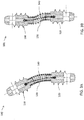
- the tether is preferably without tension in the neutral position of FIGS. 2A-2C , in which the coils of spring (130) are preferably closed.
- the length is preferably chosen such that, during lateral flexion as shown in FIG.
- tether (140) is gradually pulled tight, taking the shortest path through the inside of spring (130), and reaches a limit only at the design limit of flexion of the joint, which depends upon the joint but may be, for example, around 15 degrees.
- Tether (140) is particularly effective at limiting shear motion, such as is illustrated in FIG. 3B , where blocks (110, 120) start to undergo relative motion laterally without angular flexion.
- Such a motion is accompanied by formation of a "S-bend" curvature in spring (130) in which coils become separated on opposite sides of spring (130) at different regions along its length, leading both to an increase in the vertical height with lateral motion and tending to extend the path of tether according to the hypotenuse of a triangle formed by the height and the lateral displacement.
- tether (140) is effective to arrest such lateral shear motion after a small displacement, thereby preventing further deflection of the spring and maintaining stability of the overall structure under a wide range of stress conditions.
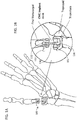
- the device as illustrated in FIG. 1 is an implant device (100) intended to replace of a joint of the human body, and specifically in this example, to replace the carpometacarpal (CMC) joint at the base of the human thumb.
- the implant device (100) is in the form of a prosthesis composed of three elements or members.
- the first rigid block (110) serves as an anchoring bit to be implanted within the first metacarpal bone of the thumb.
- the other rigid block (120) serves as an anchoring bit to be implanted within the trapezium of the wrist.
- the flexible bridging element (130) bridges between the two rigid blocks (110 and 120). When a tendon pulls one of the connected bones adjacent to the joint, the flexible bridging element (130) is deflected accordingly and allows the bone to perform its desired motion.
- the flexible bridging element is designed to provide enough strength to hold the bones on two sides of the joint in the correct place. In this action the flexible bridging element (130) mimics the action of the ligament tissue that surrounds a normally functioning joint. On the other hand flexible bridging element (130) is sufficiently flexible to allow the tendon to pull the bones to the desired position without much effort. In the case of the CMC joint, these properties combine to provide a relatively large range of motion and an improved pinch strength.
- the replacement joint is provided without causing functional damage to surroundings bones and joints because the implant is anchored only to the bones of the joint (In this example, the first metacarpal bone of the thumb and the trapezium) without using other surrounding bones (for example the trapezoid) or tendons for anchoring.
- the helical spring exhibits certain advantages over a leaf spring (cantilever elastic beam): It has low stiffness for deflection but high resistance to buckling. As a result, on one hand, the helical spring (130) can withstand relatively high axial compression force and, on the other hand, it is easily flexed by applying relatively low moments.
- the helical spring (130) is preferably made of high elasticity materials such as but not limited to stainless steel AISI 302.
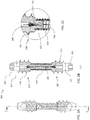
- the helical spring (130) as illustrated here in this non-limiting example is mounted on a threaded protrusion (111) which serves as the head portion of the anchoring bits (110 and 120).
- the helical spring (130) is fastened to the protrusion (111) by the thread, or by any other suitable anchoring configuration.
- the coils of the spring act as threading, tightening into engagement with threaded protrusion (111) like a threaded nut.
- the spring could also be fastened by welding, soldering, etc.
- the extension of the helical spring is limited by tether (140), referred to also as an "internal wire".
- the internal wire (140) is preferably a threaded wire - a structure that provide high strength for tension loads and great flexibility for bending.
- the internal wire (140) is preferably made of high elasticity materials such as but not limited to stainless steel ASME 302 and Super Elastic Nitinol. In order to ensure high tensile strength in combination with high flexibility, certain particularly preferred implementations employ a multi-strand metal cable for tether (140).
- the internal wire (140) may advantageously be fastened to the anchoring bits (110 and 120) by a loop (141).
- the internal wire (140) runs through hole (112) form a loop (141) and return to the hole (112). Because the Loop is too wide to pass through the hole (112) it lock the wire (140) to the anchoring bit (110 or 120).
- the Loop (141) can be formed by soldering (113), welding, adhesives, etc.
- the internal wire (140) is fastened to the anchoring blocks (110, 120) by clamping screw (114). It worth noting that fastening of wire (140) to a block (110 or 120) may be implemented using many other conventional techniques such as but not limited to welding, soldering adhering etc.
- Limiting the extension of the helical spring (130) as described above secures the parts of the joint (100) together and provides limits to its range of motion.
- the suggested artificial joint (100) mimics the action of the ligament tissue in a normal joint.
- the first and second bone-anchoring portions are of generally cone shape such that it could be introduced by pushing into the spongy part of the bone.
- the first and second anchoring bits (120 and 110) that are illustrated in FIGS. 2A-5 have a generally conical tip (115) that allows it to be introduced into the first metacarpal bone of the thumb and into the trapezium (in this example) by pushing the cone tip (115) into the Trabecular (spongy) part of the bone.
- the internal wire (140) is fastened to the anchoring bits (110, 120) by loop (141).
- the internal wire (140) runs through hole (112) in bushing (118). Then it forms a loop (141) and then returns to the hole (112).
- This approach is similar to the example in FIG. 2C , but in this example, the loop is secured within the blind hole (112b) at the bottom of the internal thread 119. In this arrangement there is no need to use additional process such as welding, soldering, adhering, etc. to secure the loop.
- the cone shape could be of sharp shape because there is no axial hole that runs through the cone as in the examples illustrated in FIGS. 2A-4 .
- the first and second anchoring bits (110, 120) elements are having protruded self-tapping like thread (116) that allows securely anchoring the element to the Trabecular (spongy) part of the bone.
- the bits (110, 120) preferably have lateral through holes (117) that are used to fasten the bit to the bone by use of standard orthopedic locking screws (151, 152 shown in FIG. 1B ).
- portions of the surfaces of the first and second anchoring elements are coated with biocompatible metallic porous coating, for example, as described in US 3,605,123 .
- This coating provides enhanced bone fixation.
- the particles composed the porous coating layer may be deposited by any one of a number of well-known processes including but not limited to a flame-plasma process, in which several parameters are controlled as functions of the size of the particles.
- anchoring bits (110, 120) illustrated in FIGS. 2A-5 may be coated in such a way.
- the at least one shear-limiting element is implemented as a first rigid extension projecting from first head portion (110b) along the inside of helical spring (130) and a second rigid extension projecting from second head portion (120b) along the inside of helical spring (130).
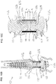
- These rigid projections, labeled (101) are best seen in the enlarged cut-away view of FIG. 10C .
- Projections (101) preferably have convexly-curved lateral surfaces, and preferably extend towards each other so as to together span a majority of an unsupported length of helical spring (130) between first and second head portions (110b, 120b).
- the "unsupported length" of spring (130) is the portion of the spring which is free to take part in motion of the joint prosthesis and, in this case, corresponds to the space between the regions caught between the head portions and the inner bores of flange elements, described further below.
- projections (101) project distances d 1 , and d 2 , respectively, from first and second head portions (110 b , 120 b ), and a remaining space between the projections in the neutral state of the joint is a. Since d 1 + d 2 > a , this configuration satisfies the aforementioned preferred condition that the projections together span a majority of the unsupported length of the helical spring.
- projections (101) The significance of projections (101) will be best understood with reference to FIG. 11B which shows a partially cut-away view of the prosthesis during application of lateral shear forces.
- the presence of projections (101) limits the extent to which lateral deflection of helical spring (130) can occur. Specifically, where convex lateral surfaces are provided, as the spring starts to deflect laterally, progressively more coils of the spring come into contact with the surface of projections (101), thereby immobilizing those coils so that no further deflection of those coils can occur, and so that the free length of the spring progressively shortens.
- the projections thus effectively delimit a maximum lateral (shear) deflection within bounds that maintain stability and structural integrity of the spring.
- the spring may be either of a normally-closed or a normally-open coil configuration.
- the spring is advantageously implemented with proportions which tend to enhance stability of the spring under axial loading.
- Particularly preferred implementations use an unsupported length of the spring which is no more than twice the diameter of the helical spring, and most preferably no more than about 1.4 times the diameter of the helical spring.
- loads transferred through prosthesis (100) are transferred to the strong cortical bone of the adjacent bones, and not to the softer inner cancellous bone.
- Anchoring of the prosthesis to the cortical bone may be achieved either through the use of transverse locking screws that pass transversely through the bone anchor portion and through the layers of cortical bone, as illustrated in FIGS. 1A and 1B , or by use of a flange which distributes loads over a sufficient area of the surface of the bone adjacent to the joint to reach the cortical periphery.
- Certain further aspects of the present invention relate to particular configurations and additional functionality related to prostheses employing flanges.
- each rigid block provided with a bone anchor portion is also provided with a flange element (102) including a flange (103).
- Flange element (102) is configured to be displaceable relative to the respective bone anchor so that, after fixation of the bone anchor within the bone, flange (103) is displaced until it comes into contact with the bone, thereby distributing forces transferred through the prosthesis over a contact surface of the flange against the first bone.
- flange element (102) to be displaced relative to the bone anchor portion is valuable in that it allows the bone anchor portion to be well seated in the bone before the flange is deployed against the bone tissue, thereby facilitating intimate contact of both the bone anchor and the flange with the bone tissue.
- the flange element provides various additional, or alternative, advantageous structures and functions, which will now be detailed.
- a further set of preferred features of the flange element (102) relate specifically to embodiments in which the flexible bridging element is a helical spring, as in FIGS. 9-15 .
- first head portion (110 b ) is configured for insertion into a first end of helical spring (130), and flange element (102) has a central bore (104) for deployment around helical spring (130).
- the outside surface of first head portion (110 b ) and central bore (104) of flange element (102) are advantageously configured to lock the helical spring therebetween.
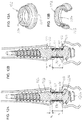
- central bore (104) has a helical groove, best seen in FIGS. 13A and 13B , configured for engaging an outside surface of coils of helical spring (130).
- Flange element (102) is thus displaceable relative to bone anchor portion (110 a ) by threaded motion along helical spring (130), i.e., as if helical spring (130) were a bolt on which flange element (102) is engaged.
- the helical groove may have a groove shape conforming to at least part of the external surface of the helical spring, or may be implemented as a conventional screw-thread cross-section, or any other desired cross-sectional shape.
- an outside surface of first head portion (110 b ) has a peripheral recess (105), best seen in FIG. 10C , for receiving at least an end coil of helical spring (130).
- head portion (110 b ) is here preferably formed with a slight outward conical angle which slightly stretches the diameter of the coils of helical spring (130) as they are forced over the head portion during assembly, and at least the end coil reverts to its relaxed diameter when it encounters recess (105), providing a snap-lock engagement of helical spring (130) onto head portion (110 b ).
- flange element (102) When flange element (102) is subsequently advanced according to its threaded motion to a position overlapping recess (105), it is effective to trap the end coil of helical spring (130) within recess (105). Specifically, in order to retract over head portion (110 b ), the end coil would need to expand outwards and seat itself neatly into the helical groove on the inside surface of central bore (104). However, axial forces are ineffective to generate such a radial outward displacement, resulting in a highly effective locking effect which abrogates the need for welding or other fixing techniques.
- a further issue that is preferably addressed by the flange features of the present invention relates to adjustability in view of differing amounts of bone that are removed by a surgeon.
- all structurally compromised tissue from the joint and adjacent bones is first removed.
- the surgeon frequently makes a judgment call during the procedure itself as to how much tissue should be removed, since the exact extent of tissue damage around the joint may not be evident from non-invasive imaging modalities.
- this issue is addressed by providing a set of at least two, and typically 3-6, flange elements (102) usable interchangeably to engage the outer surface of the coils of the helical spring.
- the different flange elements differ from each other in an axial distance from flange (103) to the nearer an end of central bore (104).
- FIGS. 12A and 12B An example illustrating the use of two different flange elements (102) of different axial dimensions is illustrated in FIGS. 12A and 12B , where FIG. 12A illustrates a case where relatively little bone was sectioned, and a short flange element (102) is used to provide abutment to the remaining bone covering a gap b 1 .
- FIG. 12A illustrates a case where relatively little bone was sectioned
- a short flange element (102) is used to provide abutment to the remaining bone covering a gap b 1 .
- FIG. 12B illustrates a case of similar joint geometry, and with a similar overall length of the thumb, but where a larger proportion of the distal bone was cut away during the preparatory procedure.
- a flange element (102) with a longer axial dimension compensates for a larger gap b 2 and ensures that intimate bone contact and effective transfer of load to the cortical bone are still achieved.
- the replacement joint (100) is here equipped with two adjustable flanges.
- each side of the replacement joint is seated into the bone, by use of a self-tapping bone anchoring configuration and/or with locking screws, at the desired position, so as to ensure that the overall natural length of the finger/thumb will be preserved.
- the location of the flange is adjusted to close the flange surface against the tissue, thereby distributing forces to the cortical exterior of the bone and/or clamping the end of the helical spring and defining the extent of the unsupported portion of the spring which takes part in flexion of the joint.
- the desired anatomy of the joint is maintained, including the length of the thumb in this example of the CMC joint.
- the flange prevents application of localized pressure in the contact area between the locking screw and the bone.
- the CMC replacement joint thus preferably serves as an adjustable spacer that maintains a fixed predetermined gap between the Trapezium and the metacarpal bone base and thus keeps the original length of the thumb. This predetermined length is well preserved with minimal deterioration over time.
- Arthritic changes reduces the effective contact surfaces of the CMC joint, consequently increasing the concentrated pressure on the joint and accelerating the further damages to the joint cartilage.
- the use of two adjustable flanges, or interchangeable flanges chosen to be of the required length dimension, helps to reduce any localized application of pressure by enlarging the contact surfaces of the joint.
- the arthritic changes in the CMC joint occur according to some theories due to gradually increased articular ligament loosening which renders the joint unstable. Instability causes the creation of concentrated forces and pressures unevenly distributed on the articular cartilage result in excessive attrition and cartilage abrasion.
- the CMC replacement joint provided by embodiments of the present invention maintains metacarpus-trapezium stability while allowing the necessary degree of metacarpus free motion with no need to reconstruct any ligament.
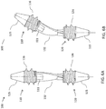
- the flexible bridging structure is implemented as a leaf spring (132), preformed with a helical twist that turns through at least 90 degrees along a length of the leaf spring.
- the leaf spring (132) is twisted about its length by at least about 90° such that it allows deflection in any lateral direction.
- the helical twist for any given direction of lateral deflection, at least some portion of the leaf spring faces with its smallest dimension in the required flexion direction so as to facilitate the required flexion.
- the spring beam (132) is fastened to the protrusion (111) by welding, soldering, adhering, etc.
- the spring beam (130) is preferably made of high elasticity materials suitable for implementation such as but not limited to stainless steel AISI 316L or AISI 316LVM comply with ASTM F138.
- the rigid blocks (110, 120) have self-tapping bone-anchor portions (116 and 126) that securely anchor the element to the Trabecular (spongy) part of the bone.
- threads (116, 126) are opposite one to each other such that by turning the implant in one direction (say counter clockwise) the threads on both anchoring bits (110, 120) screw into the bones and on each side fasten it to the joint.
- This structure is typically more robust then the joint presented in FIG. 2 as the implant is a single body such that there is typically no need for additional parts to limit its range of motions.
- FIGS. 6A-7B the anchoring bits (110, 120) could also coated with biocompatible metallic porous coating as discussed above.
- the example of FIGS. 7A-7B is similar to that of FIGS. 6A-6D , but additionally features adjustable flanges (102), with structure and functionality as discussed above.
- the flanges do not serve a locking function in relation to the flexible bridging structure, and can therefore be adjusted along the length of a relatively long range of adjustment, typically along a dedicated threaded neck portion of the first and second rigid blocks, without requiring a set of different sized flanges.
- the flexible bridging element (130) is marked with longitudinal (133) and circumferential (134) crossed marks. Those marks (133 and 134) assist the surgeon to introduce the locking screw (151 and 152 shown in FIG. 1 ) through the bone to the right location within the locking hole (117).
- the surgeon can be assisted with jig or template (200) illustrated in FIG. 8A .
- the jig (200) has a longitudinal (233) and crossed lateral (234) slots.
- the locking holes (117) are in correct position against the location holes (217) of the jig (200) so that the surgeon can drill through the holes (217) into the bone and then introduce the locking screws (151 and 152) to the locking holes.
- the human CMC Joint is a Saddle type joint providing stability together with greater flexibility than a hinge or gliding joint.
- the mobile metacarpus bone which sits on the saddle is able to move in an oval shape motion relative to the trapezium by a rolling type of motion that should prevent cartilage abrasion.
- the replacement joints according to certain embodiments described herein mimic this saddle joint feature by using a flexible helical spring linking the joint components (MC-Trapezium) and enables rolling motion with no friction and abrasion of its components.
- the above mentioned flexible helical spring restores the CMCJ kinematics and simply determines the metacarpal bone movements by its unique design.
- FIGS. 14 and 15 depending upon the degree of damage or deterioration of the trapezium, it may in some cases be necessary to remove a major part, or the entirety, of the trapezium. It is noted that the natural properties of the joints between the scaphoid and the trapezium and between the trapezium and the first metacarpal have similar mechanical properties, whereas the trapezium is essentially immobile relative to the trapezoid.
- One particular aspect of the present invention takes advantage of this observation by using the trapezoid to anchor an intermediate block, effectively serving as a prosthetic trapezium, and employs two of the aforementioned flexible bridging structures (of any of the disclosed types) to bridge between this intermediate block and the bone-anchoring blocks fixed to the scaphoid and the first metacarpal.
- two of the aforementioned flexible bridging structures of any of the disclosed types to bridge between this intermediate block and the bone-anchoring blocks fixed to the scaphoid and the first metacarpal.
- FIGS. 14 and 15 One such example is illustrated in FIGS. 14 and 15 .
- the second rigid block (120) that forms a joint with first rigid block (110) and flexible bridging structure (130) is an intermediate block of the prosthesis, which further includes a third rigid block (160) having a bone anchor portion (162) for fixation within the second bone (here, the scaphoid) and a third head portion (164) to remain projecting from the second bone.
- a second flexible bridging structure (166) is configured to bridge between the second rigid block (120) and the third rigid block (160).
- Second rigid block (120) is in this case preferably rigidly anchored to the trapezoid, such as through a bone screw (168).
- each of the two flexible joints i.e., between rigid blocks (110) and (120) and between rigid blocks (120) and (160), are preferably according to one or other of the embodiments described in detail above.
- Tightenable bone-contact flanges are only provided on the sides of the joints abutting the metacarpal and scaphoid bones, while attachment of the bridging structures to the intermediate block (120) is typically via pre-formed permanent connection, such as by welding.
- This aspect of the present invention is considered to be of particular significance as a method for forming a joint in the human hand after removal of a trapezium, where the method includes the steps of:
Landscapes
- Health & Medical Sciences (AREA)
- Orthopedic Medicine & Surgery (AREA)
- Cardiology (AREA)
- Oral & Maxillofacial Surgery (AREA)
- Transplantation (AREA)
- Engineering & Computer Science (AREA)
- Biomedical Technology (AREA)
- Heart & Thoracic Surgery (AREA)
- Vascular Medicine (AREA)
- Life Sciences & Earth Sciences (AREA)
- Animal Behavior & Ethology (AREA)
- General Health & Medical Sciences (AREA)
- Public Health (AREA)
- Veterinary Medicine (AREA)
- Prostheses (AREA)
Claims (14)
- Prothèse (100) destinée à remplacer une articulation entre un premier os et un second os dans une main ou un pied humain, la prothèse comprenant :(a) un premier bloc rigide (110) comprenant une partie d'ancrage osseux (110a) pour la fixation à l'intérieur du premier os et une première partie de tête (110b) pour rester en saillie à partir du premier os ;(b) un deuxième bloc rigide (120) comprenant une deuxième partie de tête (120b) ; et(c) une structure de pontage flexible comprenant un ressort hélicoïdal (130) déployé pour faire un pont entre ladite première partie de tête (110b) et ladite deuxième partie de tête (120b), ledit ressort hélicoïdal étant orienté de telle sorte qu'un axe central dudit ressort hélicoïdal (130) est sensiblement aligné avec un axe central de ladite partie d'ancrage osseux (110a) ;caractérisé en ce que la prothèse (100) comprend en outre :(d) une première saillie rigide (101) s'étendant à partir de ladite première partie de tête (110b) le long de l'intérieur dudit ressort hélicoïdal (130) et une seconde saillie rigide (101) s'étendant à partir de ladite deuxième partie de tête (120b) le long de l'intérieur dudit ressort hélicoïdal (130), lesdites première et seconde saillies (101) rigides étant déployées à l'intérieur d'un volume interne dudit ressort hélicoïdal de manière à limiter une étendue de déformation par cisaillement appliquée audit ressort hélicoïdal.
- Prothèse selon la revendication 1, lesdites première et seconde saillies (101) ayant des surfaces latérales incurvées de manière convexe.
- Prothèse selon la revendication 1, lesdites première et seconde saillies (101) s'étendant l'une vers l'autre de manière à s'étendre ensemble sur une majorité d'une longueur non supportée dudit ressort hélicoïdal (130) entre lesdites première et deuxième parties de tête (110b, 120b).
- Prothèse selon l'une quelconque des revendications précédentes, un espace se trouvant à l'intérieur dudit ressort hélicoïdal (130) entre lesdites première et seconde saillies (110b, 120b).
- Prothèse selon l'une quelconque des revendications précédentes, comprenant en outre :un élément de bride (102) comportant une bride (103),ladite première partie de tête (110b) étant conçue pour être insérée dans une première extrémité dudit ressort hélicoïdal (130), et ledit élément de bride (102) ayant un alésage central (104) pour le déploiement autour dudit ressort hélicoïdal (130), une surface extérieure de ladite première partie de tête (110b) et dudit alésage central (104) dudit élément de bride (102) étant conçue pour verrouiller ledit ressort hélicoïdal (130) entre eux.
- Prothèse selon l'une quelconque des revendications 1 à 4, comprenant en outre :un élément de bride (102) comportant une bride (103),ledit élément de bride (102) étant conçu pour être déplaçable par rapport audit ancrage osseux (110a) de telle sorte que, après fixation dudit ancrage osseux (110a) dans le premier os, ladite bride (103) est déplacée jusqu'à ce que ladite bride vienne en contact avec le premier os, répartissant ainsi les forces transférées à travers la prothèse sur une surface de contact de ladite bride (103) contre le premier os.
- Prothèse selon la revendication 5 ou la revendication 6, ledit alésage central (104) ayant une rainure hélicoïdale conçue pour entrer en prise avec une surface extérieure de spires dudit ressort hélicoïdal (130), ledit élément de bride (102) étant déplaçable par rapport audit ancrage osseux (110a) par un mouvement fileté le long dudit ressort hélicoïdal (130).
- Prothèse selon l'une quelconque des revendications 5 à 7, une surface extérieure de ladite première partie de tête (110b) ayant un évidement (105) périphérique pour recevoir au moins une spire d'extrémité dudit ressort hélicoïdal (130), et ledit alésage central (104) dudit élément de bride (102) étant conçu pour piéger ladite spire d'extrémité dudit ressort hélicoïdal (130) à l'intérieur dudit évidement (105).
- Prothèse selon l'une quelconque des revendications 5 à 8, ledit élément de bride (102) étant l'un d'un ensemble d'au moins deux éléments de bride (102) utilisables de manière interchangeable pour entrer en prise avec ladite surface extérieure desdites spires dudit ressort hélicoïdal (130), lesdits au moins deux éléments de bride (102) différant l'un de l'autre sur une distance axiale de ladite bride (103) à une extrémité dudit alésage central (104).
- Prothèse selon l'une quelconque des revendications 1 à 9, ledit deuxième bloc rigide (120) comprenant en outre une partie d'ancrage osseux (120a) pour la fixation à l'intérieur du second os.
- Prothèse selon la revendication 10, la prothèse (100) étant conçue pour former une articulation entre un premier métacarpien et un trapèze.
- Prothèse selon l'une quelconque des revendications 1 à 9, ledit deuxième bloc rigide (120) étant un bloc intermédiaire de la prothèse, la prothèse comprenant en outre :(a) un troisième bloc rigide (160) comprenant une partie d'ancrage osseux (162) pour la fixation à l'intérieur du second os et une troisième partie de tête (164) pour rester en saillie du second os ; et(b) une seconde structure de pont flexible (166) conçue pour faire un pont entre ledit deuxième bloc rigide (120) et ledit troisième bloc rigide (160).
- Prothèse selon la revendication 12, la prothèse étant conçue pour former une articulation entre un premier métacarpien et un scaphoïde après le retrait d'un trapèze.
- Prothèse selon la revendication 13, ledit deuxième bloc (120) étant conçu pour un ancrage rigide à un trapèze.
Applications Claiming Priority (3)
| Application Number | Priority Date | Filing Date | Title |
|---|---|---|---|
| US201562213732P | 2015-09-03 | 2015-09-03 | |
| US201562255540P | 2015-11-16 | 2015-11-16 | |
| PCT/IB2016/055302 WO2017037686A1 (fr) | 2015-09-03 | 2016-09-05 | Prothèse pour remplacer une articulation dans une main ou un pied humain |
Publications (3)
| Publication Number | Publication Date |
|---|---|
| EP3344193A1 EP3344193A1 (fr) | 2018-07-11 |
| EP3344193A4 EP3344193A4 (fr) | 2018-11-21 |
| EP3344193B1 true EP3344193B1 (fr) | 2020-12-23 |
Family
ID=58187010
Family Applications (1)
| Application Number | Title | Priority Date | Filing Date |
|---|---|---|---|
| EP16840959.7A Not-in-force EP3344193B1 (fr) | 2015-09-03 | 2016-09-05 | Prothèse pour remplacer une articulation dans une main ou un pied humain |
Country Status (6)
| Country | Link |
|---|---|
| US (1) | US10682237B2 (fr) |
| EP (1) | EP3344193B1 (fr) |
| JP (1) | JP2018526082A (fr) |
| CN (1) | CN107949347B (fr) |
| IL (1) | IL257574A (fr) |
| WO (1) | WO2017037686A1 (fr) |
Families Citing this family (10)
| Publication number | Priority date | Publication date | Assignee | Title |
|---|---|---|---|---|
| CN106726011B (zh) * | 2017-03-28 | 2019-06-28 | 郭文来 | 儿童性掌骨植入性假体 |
| US10945763B2 (en) | 2018-05-31 | 2021-03-16 | Texas Scottish Rite Hospital For Children | Orthopedic spring hinge system and methods thereof |
| JP7290301B2 (ja) * | 2018-09-19 | 2023-06-13 | 株式会社共進 | 接続構造体及びその製造方法 |
| CN110013361A (zh) * | 2019-04-26 | 2019-07-16 | 中国人民解放军联勤保障部队第九二〇医院 | 一种耐用型仿生合金指关节替换件 |
| CN110368145B (zh) * | 2019-08-05 | 2024-04-12 | 北京爱康宜诚医疗器材有限公司 | 指关节假体 |
| IT202000016813A1 (it) | 2020-07-10 | 2022-01-10 | Leopoldo CARUSO | Dispositivo protesico per dita. |
| CN112168430A (zh) * | 2020-10-28 | 2021-01-05 | 北京积水潭医院 | 治疗短管骨干骨缺损的人工假体 |
| US11497527B1 (en) | 2021-09-09 | 2022-11-15 | Texas Scottish Rite Hospital For Children | Orthopedic spring hinge systems and methods |
| US20250107900A1 (en) * | 2023-10-01 | 2025-04-03 | Djit Medtech, Inc. | Flexible Connector for an Implantable Joint Replacement Device |
| US12290445B1 (en) | 2024-05-03 | 2025-05-06 | Djit Medtech, Inc. | Joint implants with bone interface connectors |
Family Cites Families (41)
| Publication number | Priority date | Publication date | Assignee | Title |
|---|---|---|---|---|
| US3605123A (en) | 1969-04-29 | 1971-09-20 | Melpar Inc | Bone implant |
| US3990116A (en) * | 1974-10-17 | 1976-11-09 | Fixel Irving E | Pretensioned prosthetic device for skeletal joints |
| CH602091A5 (fr) * | 1976-06-03 | 1978-07-31 | Huggler Arnold | |
| US4164793A (en) * | 1978-04-26 | 1979-08-21 | Swanson Alfred B | Lunate implant |
| US4229840A (en) * | 1978-08-01 | 1980-10-28 | Pfizer Inc. | Total trispherical wrist prosthesis |
| US4198712A (en) * | 1978-10-13 | 1980-04-22 | Swanson Alfred B | Scaphoid implant |
| SE466732B (sv) * | 1987-10-29 | 1992-03-30 | Atos Medical Ab | Ledprotes, innefattande en ledkropp mellan ett par tappar foer infaestning i ben |
| SE466936B (sv) * | 1989-04-25 | 1992-05-04 | Branemark Per Ingvar | Foerankringselement foer uppbaerande av proteser |
| SE464961B (sv) * | 1989-11-15 | 1991-07-08 | Volvo Ab | Ledprotes, i synnerhet foer fingerleder |
| SE9001430D0 (sv) * | 1990-04-23 | 1990-04-23 | Braanemark Per Ingvar | Artificiell ledmekanism |
| US5423816A (en) * | 1993-07-29 | 1995-06-13 | Lin; Chih I. | Intervertebral locking device |
| US5879396A (en) * | 1993-12-28 | 1999-03-09 | Walston; D. Kenneth | Joint prosthesis having PTFE cushion |
| IT1277790B1 (it) * | 1995-02-17 | 1997-11-12 | Tecres Spa | Protesi metacarpo-falangea ed interfalangea per articolazioni della mano o del piede |
| US5534033A (en) * | 1995-06-05 | 1996-07-09 | Carbomedics, Inc. | Orthopedic prosthetic implants with pyrolytic carbon or ceramic articulating surfaces |
| FI101933B (fi) * | 1995-06-13 | 1998-09-30 | Biocon Oy | Nivelproteesi |
| SE510125C2 (sv) * | 1996-01-22 | 1999-04-19 | Handevelop Ab | Ledersättningsanordning |
| AU7635198A (en) * | 1997-06-18 | 1999-01-04 | Andre Bahler | Endoprosthesis for a joint, in particular a finger, toe or wrist joint |
| US7824445B2 (en) * | 1999-07-26 | 2010-11-02 | Ladislau Biro | Corpectomy vertebral body replacement implant system |
| JP3614802B2 (ja) * | 2001-08-27 | 2005-01-26 | 有限会社エイド−ル | 人工関節 |
| WO2004016217A2 (fr) * | 2002-08-15 | 2004-02-26 | David Gerber | Disque intervertebral artificiel controle |
| GB0219758D0 (en) * | 2002-08-24 | 2002-10-02 | Grampian Univ Hospitals | Device |
| EP1651150B1 (fr) * | 2003-08-07 | 2021-03-24 | Dynamic Spine, Inc. | Dispositif de prothese intervertebrale et dispositifs associes permettant d'implanter ledit dispositif de prothese |
| AU2004318050A1 (en) * | 2004-04-02 | 2005-10-13 | Synthes Gmbh | Modular intervertebral implant or intervertebral disc prosthesis |
| US7708739B2 (en) * | 2005-03-31 | 2010-05-04 | Depuy Products, Inc. | Controlled force impacting device |
| US20100070043A1 (en) * | 2005-08-04 | 2010-03-18 | Kitchen Michael S | Shape memory orthopedic joint |
| US7976580B2 (en) * | 2005-08-18 | 2011-07-12 | Mayo Foundation For Medical Education And Research | Semi-constrained 1st carpometacarpal implant arthroplasty and method |
| US20070233255A1 (en) * | 2006-03-06 | 2007-10-04 | Vermillion Technologies, Llc | Intervertebral disc replacement prosthesis |
| EP2203132A4 (fr) * | 2007-09-17 | 2012-11-28 | Linares Medical Devices Llc | Ligaments artificiels pour applications d'articulations |
| EP2653135B1 (fr) * | 2007-11-02 | 2015-02-18 | Biomet UK Limited | Prothèse pour simuler les cinématiques naturelles |
| SE533438C2 (sv) * | 2008-05-06 | 2010-09-28 | Swemac Innovation Ab | Ledprotes |
| KR20110073452A (ko) * | 2008-08-15 | 2011-06-29 | 키네틱 스파인 테크놀로지스 인크. | 뼈 고정나사 |
| AU2010215828A1 (en) * | 2009-02-19 | 2011-09-22 | Nextremity Solutions, Llc | Bone joining apparatus and method |
| US8343227B2 (en) * | 2009-05-28 | 2013-01-01 | Biomet Manufacturing Corp. | Knee prosthesis assembly with ligament link |
| WO2013130902A1 (fr) * | 2012-03-01 | 2013-09-06 | Solana Surgical, Llc | Œillet à utiliser avec un implant chirurgical |
| US9757247B2 (en) * | 2012-10-01 | 2017-09-12 | DePuy Synthes Products, Inc. | Interbody fusion implant |
| US20150025641A1 (en) * | 2012-11-16 | 2015-01-22 | Marcos V. Masson | Shock-absorbing humeral implant for shoulder arthroplasty |
| WO2015088403A1 (fr) * | 2013-12-10 | 2015-06-18 | Swemac Innovation Ab | Élément de fixation et élément de liaison pour une prothèse d'articulation de pouce carpo-métacarpienne, et prothèse d'articulation de pouce carpo-métacarpienne |
| US10624748B2 (en) * | 2014-03-07 | 2020-04-21 | Arthrosurface Incorporated | System and method for repairing articular surfaces |
| GB2532005A (en) * | 2014-10-31 | 2016-05-11 | Biomet Uk Ltd | Improved ligament fixing and a method of attaching a ligament |
| TW201707653A (zh) * | 2015-08-18 | 2017-03-01 | Pao Nan Biotech Co Ltd | 腓骨截斷處之防止骨融合銜接裝置 |
| US10537436B2 (en) * | 2016-11-01 | 2020-01-21 | DePuy Synthes Products, Inc. | Curved expandable cage |
-
2016
- 2016-09-05 US US15/753,975 patent/US10682237B2/en not_active Expired - Fee Related
- 2016-09-05 JP JP2018507645A patent/JP2018526082A/ja active Pending
- 2016-09-05 CN CN201680051015.8A patent/CN107949347B/zh not_active Expired - Fee Related
- 2016-09-05 WO PCT/IB2016/055302 patent/WO2017037686A1/fr not_active Ceased
- 2016-09-05 EP EP16840959.7A patent/EP3344193B1/fr not_active Not-in-force
-
2018
- 2018-02-18 IL IL257574A patent/IL257574A/en unknown
Non-Patent Citations (1)
| Title |
|---|
| None * |
Also Published As
| Publication number | Publication date |
|---|---|
| CN107949347A (zh) | 2018-04-20 |
| CN107949347B (zh) | 2020-08-14 |
| EP3344193A1 (fr) | 2018-07-11 |
| IL257574A (en) | 2018-04-30 |
| WO2017037686A1 (fr) | 2017-03-09 |
| US10682237B2 (en) | 2020-06-16 |
| JP2018526082A (ja) | 2018-09-13 |
| US20180250139A1 (en) | 2018-09-06 |
| EP3344193A4 (fr) | 2018-11-21 |
Similar Documents
| Publication | Publication Date | Title |
|---|---|---|
| US10682237B2 (en) | Prosthesis for replacing joint in a human hand or foot | |
| JP5612577B2 (ja) | 椎体を安定させるための装置 | |
| KR101570213B1 (ko) | 동적 뼈 고정 요소 및 그 사용 방법 | |
| US11000319B2 (en) | Arthrodesis devices for generating and applying compression within joints | |
| US10799277B2 (en) | Anti-penetration bone implant device and method | |
| US20080275509A1 (en) | Mounts for implantable extra-articular systems | |
| CA2904487A1 (fr) | Dispositifs et procedes d'ancrage osseux | |
| JP2011519303A (ja) | 大腿骨及び脛骨用基部構成要素 | |
| JP7739267B2 (ja) | 動的固定インプラントおよび使用方法 | |
| EP3079636B1 (fr) | Élément de fixation et élément de liaison pour une prothèse d'articulation de pouce carpo-métacarpienne, et prothèse d'articulation de pouce carpo-métacarpienne | |
| EP2299918B1 (fr) | Supports pour systèmes extra-articulaires implantables | |
| RU211377U1 (ru) | Устройство для внутрикостного остеосинтеза при переломах лодыжек с разрывом связок дистального межберцового синдесмоза | |
| US20170112537A1 (en) | Implantable Assembly for a Knee Joint and Method for Mounting an Implantable Assembly for a Knee Joint | |
| JP2008511379A (ja) | 関節プロテーゼと骨固定の方法 | |
| JPH0515294Y2 (fr) | ||
| JP2025540861A (ja) | 関節内または関節をまたいで圧迫を適用するための外科手術装置 |
Legal Events
| Date | Code | Title | Description |
|---|---|---|---|
| STAA | Information on the status of an ep patent application or granted ep patent |
Free format text: STATUS: THE INTERNATIONAL PUBLICATION HAS BEEN MADE |
|
| PUAI | Public reference made under article 153(3) epc to a published international application that has entered the european phase |
Free format text: ORIGINAL CODE: 0009012 |
|
| STAA | Information on the status of an ep patent application or granted ep patent |
Free format text: STATUS: REQUEST FOR EXAMINATION WAS MADE |
|
| 17P | Request for examination filed |
Effective date: 20180314 |
|
| AK | Designated contracting states |
Kind code of ref document: A1 Designated state(s): AL AT BE BG CH CY CZ DE DK EE ES FI FR GB GR HR HU IE IS IT LI LT LU LV MC MK MT NL NO PL PT RO RS SE SI SK SM TR |
|
| AX | Request for extension of the european patent |
Extension state: BA ME |
|
| A4 | Supplementary search report drawn up and despatched |
Effective date: 20181022 |
|
| RIC1 | Information provided on ipc code assigned before grant |
Ipc: A61F 2/42 20060101AFI20181016BHEP |
|
| DAV | Request for validation of the european patent (deleted) | ||
| DAX | Request for extension of the european patent (deleted) | ||
| STAA | Information on the status of an ep patent application or granted ep patent |
Free format text: STATUS: EXAMINATION IS IN PROGRESS |
|
| 17Q | First examination report despatched |
Effective date: 20190826 |
|
| GRAP | Despatch of communication of intention to grant a patent |
Free format text: ORIGINAL CODE: EPIDOSNIGR1 |
|
| STAA | Information on the status of an ep patent application or granted ep patent |
Free format text: STATUS: GRANT OF PATENT IS INTENDED |
|
| INTG | Intention to grant announced |
Effective date: 20200714 |
|
| GRAS | Grant fee paid |
Free format text: ORIGINAL CODE: EPIDOSNIGR3 |
|
| GRAA | (expected) grant |
Free format text: ORIGINAL CODE: 0009210 |
|
| STAA | Information on the status of an ep patent application or granted ep patent |
Free format text: STATUS: THE PATENT HAS BEEN GRANTED |
|
| AK | Designated contracting states |
Kind code of ref document: B1 Designated state(s): AL AT BE BG CH CY CZ DE DK EE ES FI FR GB GR HR HU IE IS IT LI LT LU LV MC MK MT NL NO PL PT RO RS SE SI SK SM TR |
|
| REG | Reference to a national code |
Ref country code: GB Ref legal event code: FG4D |
|
| REG | Reference to a national code |
Ref country code: DE Ref legal event code: R096 Ref document number: 602016050357 Country of ref document: DE |
|
| REG | Reference to a national code |
Ref country code: AT Ref legal event code: REF Ref document number: 1346983 Country of ref document: AT Kind code of ref document: T Effective date: 20210115 |
|
| REG | Reference to a national code |
Ref country code: IE Ref legal event code: FG4D |
|
| REG | Reference to a national code |
Ref country code: NO Ref legal event code: T2 Effective date: 20201223 |
|
| PG25 | Lapsed in a contracting state [announced via postgrant information from national office to epo] |
Ref country code: RS Free format text: LAPSE BECAUSE OF FAILURE TO SUBMIT A TRANSLATION OF THE DESCRIPTION OR TO PAY THE FEE WITHIN THE PRESCRIBED TIME-LIMIT Effective date: 20201223 Ref country code: FI Free format text: LAPSE BECAUSE OF FAILURE TO SUBMIT A TRANSLATION OF THE DESCRIPTION OR TO PAY THE FEE WITHIN THE PRESCRIBED TIME-LIMIT Effective date: 20201223 Ref country code: GR Free format text: LAPSE BECAUSE OF FAILURE TO SUBMIT A TRANSLATION OF THE DESCRIPTION OR TO PAY THE FEE WITHIN THE PRESCRIBED TIME-LIMIT Effective date: 20210324 |
|
| REG | Reference to a national code |
Ref country code: AT Ref legal event code: MK05 Ref document number: 1346983 Country of ref document: AT Kind code of ref document: T Effective date: 20201223 |
|
| REG | Reference to a national code |
Ref country code: NL Ref legal event code: MP Effective date: 20201223 |
|
| PG25 | Lapsed in a contracting state [announced via postgrant information from national office to epo] |
Ref country code: LV Free format text: LAPSE BECAUSE OF FAILURE TO SUBMIT A TRANSLATION OF THE DESCRIPTION OR TO PAY THE FEE WITHIN THE PRESCRIBED TIME-LIMIT Effective date: 20201223 Ref country code: BG Free format text: LAPSE BECAUSE OF FAILURE TO SUBMIT A TRANSLATION OF THE DESCRIPTION OR TO PAY THE FEE WITHIN THE PRESCRIBED TIME-LIMIT Effective date: 20210323 Ref country code: SE Free format text: LAPSE BECAUSE OF FAILURE TO SUBMIT A TRANSLATION OF THE DESCRIPTION OR TO PAY THE FEE WITHIN THE PRESCRIBED TIME-LIMIT Effective date: 20201223 |
|
| PG25 | Lapsed in a contracting state [announced via postgrant information from national office to epo] |
Ref country code: HR Free format text: LAPSE BECAUSE OF FAILURE TO SUBMIT A TRANSLATION OF THE DESCRIPTION OR TO PAY THE FEE WITHIN THE PRESCRIBED TIME-LIMIT Effective date: 20201223 Ref country code: NL Free format text: LAPSE BECAUSE OF FAILURE TO SUBMIT A TRANSLATION OF THE DESCRIPTION OR TO PAY THE FEE WITHIN THE PRESCRIBED TIME-LIMIT Effective date: 20201223 |
|
| REG | Reference to a national code |
Ref country code: LT Ref legal event code: MG9D |
|
| PG25 | Lapsed in a contracting state [announced via postgrant information from national office to epo] |
Ref country code: RO Free format text: LAPSE BECAUSE OF FAILURE TO SUBMIT A TRANSLATION OF THE DESCRIPTION OR TO PAY THE FEE WITHIN THE PRESCRIBED TIME-LIMIT Effective date: 20201223 Ref country code: SK Free format text: LAPSE BECAUSE OF FAILURE TO SUBMIT A TRANSLATION OF THE DESCRIPTION OR TO PAY THE FEE WITHIN THE PRESCRIBED TIME-LIMIT Effective date: 20201223 Ref country code: PT Free format text: LAPSE BECAUSE OF FAILURE TO SUBMIT A TRANSLATION OF THE DESCRIPTION OR TO PAY THE FEE WITHIN THE PRESCRIBED TIME-LIMIT Effective date: 20210423 Ref country code: EE Free format text: LAPSE BECAUSE OF FAILURE TO SUBMIT A TRANSLATION OF THE DESCRIPTION OR TO PAY THE FEE WITHIN THE PRESCRIBED TIME-LIMIT Effective date: 20201223 Ref country code: CZ Free format text: LAPSE BECAUSE OF FAILURE TO SUBMIT A TRANSLATION OF THE DESCRIPTION OR TO PAY THE FEE WITHIN THE PRESCRIBED TIME-LIMIT Effective date: 20201223 Ref country code: LT Free format text: LAPSE BECAUSE OF FAILURE TO SUBMIT A TRANSLATION OF THE DESCRIPTION OR TO PAY THE FEE WITHIN THE PRESCRIBED TIME-LIMIT Effective date: 20201223 Ref country code: SM Free format text: LAPSE BECAUSE OF FAILURE TO SUBMIT A TRANSLATION OF THE DESCRIPTION OR TO PAY THE FEE WITHIN THE PRESCRIBED TIME-LIMIT Effective date: 20201223 |
|
| PG25 | Lapsed in a contracting state [announced via postgrant information from national office to epo] |
Ref country code: PL Free format text: LAPSE BECAUSE OF FAILURE TO SUBMIT A TRANSLATION OF THE DESCRIPTION OR TO PAY THE FEE WITHIN THE PRESCRIBED TIME-LIMIT Effective date: 20201223 Ref country code: AT Free format text: LAPSE BECAUSE OF FAILURE TO SUBMIT A TRANSLATION OF THE DESCRIPTION OR TO PAY THE FEE WITHIN THE PRESCRIBED TIME-LIMIT Effective date: 20201223 |
|
| REG | Reference to a national code |
Ref country code: DE Ref legal event code: R097 Ref document number: 602016050357 Country of ref document: DE |
|
| PG25 | Lapsed in a contracting state [announced via postgrant information from national office to epo] |
Ref country code: IS Free format text: LAPSE BECAUSE OF FAILURE TO SUBMIT A TRANSLATION OF THE DESCRIPTION OR TO PAY THE FEE WITHIN THE PRESCRIBED TIME-LIMIT Effective date: 20210423 |
|
| PG25 | Lapsed in a contracting state [announced via postgrant information from national office to epo] |
Ref country code: AL Free format text: LAPSE BECAUSE OF FAILURE TO SUBMIT A TRANSLATION OF THE DESCRIPTION OR TO PAY THE FEE WITHIN THE PRESCRIBED TIME-LIMIT Effective date: 20201223 Ref country code: IT Free format text: LAPSE BECAUSE OF FAILURE TO SUBMIT A TRANSLATION OF THE DESCRIPTION OR TO PAY THE FEE WITHIN THE PRESCRIBED TIME-LIMIT Effective date: 20201223 |
|
| PLBE | No opposition filed within time limit |
Free format text: ORIGINAL CODE: 0009261 |
|
| STAA | Information on the status of an ep patent application or granted ep patent |
Free format text: STATUS: NO OPPOSITION FILED WITHIN TIME LIMIT |
|
| PG25 | Lapsed in a contracting state [announced via postgrant information from national office to epo] |
Ref country code: DK Free format text: LAPSE BECAUSE OF FAILURE TO SUBMIT A TRANSLATION OF THE DESCRIPTION OR TO PAY THE FEE WITHIN THE PRESCRIBED TIME-LIMIT Effective date: 20201223 |
|
| 26N | No opposition filed |
Effective date: 20210924 |
|
| PG25 | Lapsed in a contracting state [announced via postgrant information from national office to epo] |
Ref country code: ES Free format text: LAPSE BECAUSE OF FAILURE TO SUBMIT A TRANSLATION OF THE DESCRIPTION OR TO PAY THE FEE WITHIN THE PRESCRIBED TIME-LIMIT Effective date: 20201223 |
|
| PG25 | Lapsed in a contracting state [announced via postgrant information from national office to epo] |
Ref country code: SI Free format text: LAPSE BECAUSE OF FAILURE TO SUBMIT A TRANSLATION OF THE DESCRIPTION OR TO PAY THE FEE WITHIN THE PRESCRIBED TIME-LIMIT Effective date: 20201223 |
|
| REG | Reference to a national code |
Ref country code: NO Ref legal event code: MMEP |
|
| REG | Reference to a national code |
Ref country code: CH Ref legal event code: PL |
|
| REG | Reference to a national code |
Ref country code: BE Ref legal event code: MM Effective date: 20210930 |
|
| PG25 | Lapsed in a contracting state [announced via postgrant information from national office to epo] |
Ref country code: IS Free format text: LAPSE BECAUSE OF FAILURE TO SUBMIT A TRANSLATION OF THE DESCRIPTION OR TO PAY THE FEE WITHIN THE PRESCRIBED TIME-LIMIT Effective date: 20210423 Ref country code: MC Free format text: LAPSE BECAUSE OF FAILURE TO SUBMIT A TRANSLATION OF THE DESCRIPTION OR TO PAY THE FEE WITHIN THE PRESCRIBED TIME-LIMIT Effective date: 20201223 |
|
| PG25 | Lapsed in a contracting state [announced via postgrant information from national office to epo] |
Ref country code: NO Free format text: LAPSE BECAUSE OF NON-PAYMENT OF DUE FEES Effective date: 20210930 Ref country code: LU Free format text: LAPSE BECAUSE OF NON-PAYMENT OF DUE FEES Effective date: 20210905 Ref country code: IE Free format text: LAPSE BECAUSE OF NON-PAYMENT OF DUE FEES Effective date: 20210905 Ref country code: BE Free format text: LAPSE BECAUSE OF NON-PAYMENT OF DUE FEES Effective date: 20210930 |
|
| PG25 | Lapsed in a contracting state [announced via postgrant information from national office to epo] |
Ref country code: LI Free format text: LAPSE BECAUSE OF NON-PAYMENT OF DUE FEES Effective date: 20210930 Ref country code: CH Free format text: LAPSE BECAUSE OF NON-PAYMENT OF DUE FEES Effective date: 20210930 |
|
| PGFP | Annual fee paid to national office [announced via postgrant information from national office to epo] |
Ref country code: GB Payment date: 20220919 Year of fee payment: 7 Ref country code: DE Payment date: 20220921 Year of fee payment: 7 |
|
| PGFP | Annual fee paid to national office [announced via postgrant information from national office to epo] |
Ref country code: FR Payment date: 20220915 Year of fee payment: 7 |
|
| PG25 | Lapsed in a contracting state [announced via postgrant information from national office to epo] |
Ref country code: HU Free format text: LAPSE BECAUSE OF FAILURE TO SUBMIT A TRANSLATION OF THE DESCRIPTION OR TO PAY THE FEE WITHIN THE PRESCRIBED TIME-LIMIT; INVALID AB INITIO Effective date: 20160905 |
|
| PG25 | Lapsed in a contracting state [announced via postgrant information from national office to epo] |
Ref country code: CY Free format text: LAPSE BECAUSE OF FAILURE TO SUBMIT A TRANSLATION OF THE DESCRIPTION OR TO PAY THE FEE WITHIN THE PRESCRIBED TIME-LIMIT Effective date: 20201223 |
|
| REG | Reference to a national code |
Ref country code: DE Ref legal event code: R119 Ref document number: 602016050357 Country of ref document: DE |
|
| PG25 | Lapsed in a contracting state [announced via postgrant information from national office to epo] |
Ref country code: MK Free format text: LAPSE BECAUSE OF FAILURE TO SUBMIT A TRANSLATION OF THE DESCRIPTION OR TO PAY THE FEE WITHIN THE PRESCRIBED TIME-LIMIT Effective date: 20201223 |
|
| GBPC | Gb: european patent ceased through non-payment of renewal fee |
Effective date: 20230905 |
|
| PG25 | Lapsed in a contracting state [announced via postgrant information from national office to epo] |
Ref country code: TR Free format text: LAPSE BECAUSE OF FAILURE TO SUBMIT A TRANSLATION OF THE DESCRIPTION OR TO PAY THE FEE WITHIN THE PRESCRIBED TIME-LIMIT Effective date: 20201223 |
|
| PG25 | Lapsed in a contracting state [announced via postgrant information from national office to epo] |
Ref country code: GB Free format text: LAPSE BECAUSE OF NON-PAYMENT OF DUE FEES Effective date: 20230905 |
|
| PG25 | Lapsed in a contracting state [announced via postgrant information from national office to epo] |
Ref country code: GB Free format text: LAPSE BECAUSE OF NON-PAYMENT OF DUE FEES Effective date: 20230905 Ref country code: FR Free format text: LAPSE BECAUSE OF NON-PAYMENT OF DUE FEES Effective date: 20230930 Ref country code: DE Free format text: LAPSE BECAUSE OF NON-PAYMENT OF DUE FEES Effective date: 20240403 |
|
| PG25 | Lapsed in a contracting state [announced via postgrant information from national office to epo] |
Ref country code: MT Free format text: LAPSE BECAUSE OF FAILURE TO SUBMIT A TRANSLATION OF THE DESCRIPTION OR TO PAY THE FEE WITHIN THE PRESCRIBED TIME-LIMIT Effective date: 20201223 |