EP3344485B1 - Dispositif d'obturation d'entrée d'air de face avant de véhicule automobile et module de face avant pour véhicule automobile - Google Patents
Dispositif d'obturation d'entrée d'air de face avant de véhicule automobile et module de face avant pour véhicule automobile Download PDFInfo
- Publication number
- EP3344485B1 EP3344485B1 EP16756685.0A EP16756685A EP3344485B1 EP 3344485 B1 EP3344485 B1 EP 3344485B1 EP 16756685 A EP16756685 A EP 16756685A EP 3344485 B1 EP3344485 B1 EP 3344485B1
- Authority
- EP
- European Patent Office
- Prior art keywords
- support frame
- motor vehicle
- shut
- cut
- flaps
- Prior art date
- Legal status (The legal status is an assumption and is not a legal conclusion. Google has not performed a legal analysis and makes no representation as to the accuracy of the status listed.)
- Not-in-force
Links
Images


Classifications
-
- B—PERFORMING OPERATIONS; TRANSPORTING
- B60—VEHICLES IN GENERAL
- B60K—ARRANGEMENT OR MOUNTING OF PROPULSION UNITS OR OF TRANSMISSIONS IN VEHICLES; ARRANGEMENT OR MOUNTING OF PLURAL DIVERSE PRIME-MOVERS IN VEHICLES; AUXILIARY DRIVES FOR VEHICLES; INSTRUMENTATION OR DASHBOARDS FOR VEHICLES; ARRANGEMENTS IN CONNECTION WITH COOLING, AIR INTAKE, GAS EXHAUST OR FUEL SUPPLY OF PROPULSION UNITS IN VEHICLES
- B60K11/00—Arrangement in connection with cooling of propulsion units
- B60K11/08—Air inlets for cooling; Shutters or blinds therefor
- B60K11/085—Air inlets for cooling; Shutters or blinds therefor with adjustable shutters or blinds
-
- B—PERFORMING OPERATIONS; TRANSPORTING
- B60—VEHICLES IN GENERAL
- B60Y—INDEXING SCHEME RELATING TO ASPECTS CROSS-CUTTING VEHICLE TECHNOLOGY
- B60Y2306/00—Other features of vehicle sub-units
- B60Y2306/13—Failsafe arrangements
-
- B—PERFORMING OPERATIONS; TRANSPORTING
- B60—VEHICLES IN GENERAL
- B60Y—INDEXING SCHEME RELATING TO ASPECTS CROSS-CUTTING VEHICLE TECHNOLOGY
- B60Y2400/00—Special features of vehicle units
- B60Y2400/30—Sensors
- B60Y2400/301—Sensors for position or displacement
- B60Y2400/3012—Sensors for position or displacement using Hall effect
-
- B—PERFORMING OPERATIONS; TRANSPORTING
- B60—VEHICLES IN GENERAL
- B60Y—INDEXING SCHEME RELATING TO ASPECTS CROSS-CUTTING VEHICLE TECHNOLOGY
- B60Y2400/00—Special features of vehicle units
- B60Y2400/30—Sensors
- B60Y2400/302—Temperature sensors
-
- B—PERFORMING OPERATIONS; TRANSPORTING
- B60—VEHICLES IN GENERAL
- B60Y—INDEXING SCHEME RELATING TO ASPECTS CROSS-CUTTING VEHICLE TECHNOLOGY
- B60Y2400/00—Special features of vehicle units
- B60Y2400/30—Sensors
- B60Y2400/308—Electric sensors
- B60Y2400/3084—Electric currents sensors
-
- Y—GENERAL TAGGING OF NEW TECHNOLOGICAL DEVELOPMENTS; GENERAL TAGGING OF CROSS-SECTIONAL TECHNOLOGIES SPANNING OVER SEVERAL SECTIONS OF THE IPC; TECHNICAL SUBJECTS COVERED BY FORMER USPC CROSS-REFERENCE ART COLLECTIONS [XRACs] AND DIGESTS
- Y02—TECHNOLOGIES OR APPLICATIONS FOR MITIGATION OR ADAPTATION AGAINST CLIMATE CHANGE
- Y02T—CLIMATE CHANGE MITIGATION TECHNOLOGIES RELATED TO TRANSPORTATION
- Y02T10/00—Road transport of goods or passengers
- Y02T10/80—Technologies aiming to reduce greenhouse gasses emissions common to all road transportation technologies
- Y02T10/88—Optimized components or subsystems, e.g. lighting, actively controlled glasses
Definitions
- the present invention relates to closure devices and more specifically to a motor vehicle front face air intake closure device as well as a front face module for a motor vehicle.
- a closure device according to the preamble of claim 1 is known from document EP 2 080 658 A1 .
- the front faces of motor vehicles are generally made up of two main air inlets called the high track and the low track separated by a bumper beam. Behind this bumper beam are generally placed the heat exchangers of the motor vehicle, such as for example that used for air conditioning of the passenger compartment or even that used for cooling the engine.
- a support frame comprising a multiplicity of flaps mounted to pivot about parallel axes and suitable for taking a multiplicity of different angular positions, between an open position and a closed position, under the action of appropriate control means.
- a shutter device similar to a louver is thus obtained which makes it possible to adjust the flow of air passing through the air inlets and arriving at the heat exchangers and thus to optimize the efficiency of these heat exchangers by as needed.
- the shutters in the closed position make it possible to reduce the vehicle's drag coefficient and thus improve its aerodynamics.
- the device allowing the passage from a closed position to an open position of the shutters comprises an actuator which may be mechanical, electric or pneumatic, causing the shutters to pivot in synchronism by means of a pivoting rod.
- the closure device breaks due to deformation movements, in particular of the bumper beam, and said closure device, more particularly the flaps of the latter, risk of come into contact with the heat exchangers which are located behind it. Following a too violent impact, the closure device damages the heat exchangers and thus increases the repair costs of the motor vehicle.
- One of the aims of the present invention is therefore to at least partially remedy the drawbacks of the prior art and to provide an improved closure device.
- the support frame comprises pre-cut portions near at least one connecting means.
- pre-cut portions are areas of weakness which during an impact, and a push at the level of the flaps or the support frame, can give way and allow movement of the parts relative to each other. For example, if the front of the vehicle is pushed in, the shutter device as a whole moves back towards the interior of the motor vehicle and the flaps then run the risk, during this inward movement, of coming into contact with the heat exchangers. When the flaps come into contact with the heat exchangers and the backward movement continues, the pre-cut portions then release, thus absorbing energy, and preventing said flaps from damaging said heat exchangers. The heat exchangers then remain relatively intact following the impact thanks to the presence of the pre-cut portions on the support frame. The vehicle thus remains functional and repair costs are also lower.
- the closure device comprises at least two sets of shutters and that the support frame comprises at least one retaining post fixed to at least one cross member of said support frame, the at least one cross member comprising pre-cut portions near at least one support post.
- the support frame further comprises pre-cut portions near the connection means between said support frame and at least one control element.
- the support frame comprises at least one retaining means of the elements capable of being detached by rupture at the level of the pre-cut portions.
- the retaining means is a stopper.
- the retaining means is an elastomeric material covering the pre-cut portions.
- the pre-cut portions are orifices passing through the support frame and arranged in dotted lines.
- the through orifices have the form of aligned segments.
- the invention also relates to a front panel module for a motor vehicle comprising a closure device as described above.
- the figure 1 shows a schematic perspective representation of a closure device in the closed position. This figure 1 shows more exactly the external face of said closure device 1, that is to say the face directed towards the outside of the motor vehicle.
- Said closure device 1 comprises a support frame 5 comprising in particular an upper cross member, a lower cross member and at least two lateral uprights connecting said cross members.
- a support frame 5 comprising in particular an upper cross member, a lower cross member and at least two lateral uprights connecting said cross members.
- Within said support frame 5 is installed at least one shutter 3.
- the latter form rows of shutters 3 parallel to each other and which form a set of shutters 3.
- a control element 13 allowing the rotation of the shutter (s) 3 between an open position (for example shown in figure 2 ), where the shutter (s) 3 are arranged so that an air flow can pass through the closure device 1, in particular inside the support frame 5, and a closed position illustrated in figure 1 , where the shutter (s) are arranged so that an air flow cannot pass through the closure device 1.
- a device 1 for shutting off an air intake on the front face of a motor vehicle comprising several assemblies flaps 3 extending over the entire width of the support frame 5.
- the sets of flaps 3 can thus be separated by a control element 13 in order to ensure their synchronous rotation or else by holding uprights 50.
- the upright or uprights 50 are in particular fixed to at least one cross member of the support frame 5.
- the retaining uprights 50 can on the contrary ensure continuity of material with the cross members of said support frame 5.
- control element 13 comprises in particular a pivoting rod 7 connected to the flaps 3 by a rib 30 perpendicular to said flap 3, generally integral with said flaps 3 and carrying a connecting pin B.
- the control element 13 also comprises an actuator 9.
- the actuator 9 can be electric, such as for example an electric motor or else pneumatic, such as for example a jack. Said actuator 9 applies an upward or downward translational movement to the pivoting rod 7, here by means of a lever 11.
- the shutters 3 can pivot about a pivot axis A defined by their connection zone 30 with the support frame 5.
- the shutter 3 is connected to the support frame 5 by a connection means at the level of the connection zone 30, the connecting means being, for example, a lug and a groove of complementary shapes.
- the connecting axis B between the flaps 3 and the connecting rod 7, being eccentric with respect to the pivot axis A, an upward or downward movement of the connecting rod 7, under the action of the actuator 9 , causes the pivoting of the flaps 3 around the pivot axis A and therefore the passage of said flaps 3 from one position to another.
- said support frame 5 comprises pre-cut portions 40.
- These pre-cut portions 40 are weakening zones, or fusible zones, which during an impact, and a thrust at the level of the flaps 3 or of the support frame 5, are able to give way and thus allow movement of the parts relative to each other.
- the pre-cut portions 40 allow a gradual, jerky or even step-by-step movement of the shutter (s) 3. For example, if the front face of the vehicle is pushed in, the shutter device 1 as a whole will.
- the flaps 3 run the risk, during this inward movement, of coming into contact with the heat exchangers.
- the pre-cut portions 40 give way, absorbing energy, and thus limit said flaps 3 from damaging said heat exchangers.
- the heat exchangers then remain relatively intact following the impact due to the presence of the pre-cut portions 40 on the support frame 5. The vehicle thus remains functional and the repair costs are also lower.
- the pre-cut portions 40 are preferably orifices passing through the support frame 5 and arranged in dotted lines.
- the length and spacing of these holes define the value of the force for which there will be failure.
- the through orifices may have the form of aligned segments, and in particular the through orifices are rectangular in shape and being aligned.
- aligned segments and in particular the through orifices are rectangular in shape and being aligned.
- the pre-cut portions 40 are produced at the level of the connection between the retaining upright 50 and the cross members of the support frame 5.
- the pre-cut portions 40 can for example be produced on the cross members of the support frame 5 or directly on the support post 50.
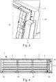
- the control element 13, as shown in figure 1 can be placed on a support upright 50. On the contrary, it can be placed close to the support frame 5, and for example be fixed at the level of one of the lateral uprights, as illustrated in figures 3 and 4 .
- the connection zone (s) between said support frame 5 and at least one control element 13 further comprises pre-cut portions 40, in particular near the connection means between the support frame 5 and the control element 13 , so that the control element 13 can be detached from the support frame 5 in the event of an impact while remaining secured to the flaps 3.
- the control element 13 is only represented by a protective cover.
- the connecting means for example, correspond to a lug and a groove of complementary shapes.
- the support frame 5 comprises at least one retaining means 61, 62 elements capable of being detached by breaking at the level of the pre-cut portions 40.
- These retaining means 61, 62 allow the flap or flaps 3 as well as the or the control elements 13 can move in the event of an impact due to the breakage of the pre-cut portions 40, but the latter are all the same limited in their movements.
- the retaining means 61, 62 may be a stop 61.
- This stop 61 ensures continuity of material with the support frame 5 or else be fixed to the latter.
- Said stop 61 and may also have an "L" shape overhanging the pre-cut portions 40.
- said stopper 61 may be present on the inner face of the support frame 5, that is to say on the side facing the interior of the vehicle, or else on the outer face of the support frame 5, that is to say on the side facing the outside of the vehicle.
- the retaining means 61, 62 may be an elastomeric material 62 covering the pre-cut portions 40.
- the elastomeric material 62 may be present on the inner face of the support frame 5, c ' that is to say on the side facing the interior of the vehicle, or else on the exterior face of the support frame 5, that is to say on the side facing the exterior of the vehicle.
- the elastomeric material 62 may for example be a thermoplastic elastomer (TPE) and be applied by overmolding the support frame 5.
- the closure device 1 makes it possible to better withstand violent shocks during accidents and in particular makes it possible to keep the heat exchangers functional even following the impact.
Landscapes
- Engineering & Computer Science (AREA)
- Chemical & Material Sciences (AREA)
- Combustion & Propulsion (AREA)
- Transportation (AREA)
- Mechanical Engineering (AREA)
- Cooling, Air Intake And Gas Exhaust, And Fuel Tank Arrangements In Propulsion Units (AREA)
Description
- La présente invention concerne les dispositifs d'obturation et plus précisément un dispositif d'obturation d'entrée d'air de face avant de véhicule automobile ainsi qu'un module de face avant pour véhicule automobile. Un dispositif d'obturation selon le préambule de la revendication 1 est connu du document
EP 2 080 658 A1 . - Le document
WO2016/030588 est considéré état de la technique selon l'article 54(3) CBE. - Les faces avant de véhicules automobiles sont généralement composées de deux entrées d'air principales dites voie haute et voie basse séparées par une poutre pare-choc. Derrière cette poutre pare-choc sont généralement placés les échangeurs de chaleur du véhicule automobile, comme par exemple celui utilisé pour la climatisation de l'habitacle ou encore celui utilisé pour le refroidissement du moteur.
- Il est également connu de disposer, dans le trajet d'air passant par les entrées d'air principales, plus généralement la voie basse, un cadre support comportant une multiplicité de volets montés pivotants autour d'axes parallèles et propres à prendre une multiplicité de positions angulaires différentes, comprises entre une position d'ouverture et une position d'obturation, sous l'action de moyens de commande appropriés.
- On obtient ainsi un dispositif d'obturation s'apparentant à une jalousie qui permet d'ajuster le débit d'air traversant les entrées d'airs et arrivant aux échangeurs de chaleur et ainsi d'optimiser l'efficacité de ces échangeurs de chaleur en fonction des besoins. De plus, à grande vitesse, les volets en position d'obturation permettent de diminuer le coefficient de traînée du véhicule et ainsi d'améliorer son aérodynamisme.
- Généralement, le dispositif permettant le passage d'une position d'obturation à une position d'ouverture des volets comporte un actionneur qui peut être mécanique, électrique ou encore pneumatique, faisant pivoter les volets en synchronisme au moyen d'une bielle de pivotement.
- Lors de chocs violent par exemple pendant un accident, le dispositif d'obturation se brise en raison de mouvements de déformation, notamment de la poutre pare-choc, et ledit dispositif d'obturation, plus particulièrement les volets de ce dernier, risque d'entrer en contact avec les échangeurs de chaleur qui sont situés derrière lui. Suite à un choc trop violent, le dispositif d'obturation endommage les échangeurs de chaleur et augmente ainsi les coûts de réparations du véhicule automobile.
- Un des buts de la présente invention est donc de remédier au moins partiellement aux inconvénients de l'art antérieur et de proposer un dispositif d'obturation amélioré.
- La présente invention concerne donc un dispositif d'obturation pour entrée d'air de face avant de véhicule automobile, comprenant :
- un cadre support,
- au moins un volet pivotant autour d'un axe de pivotement horizontal entre une position d'obturation et une position d'ouverture, ledit au moins un volet étant installé au sein du cadre support, le cadre support comprenant des moyens de liaison avec ledit au moins un volet au niveau d'une zone de liaison, et
- au moins un élément de commande (13) pilotant le positionnement du ou des volets.
- Selon l'invention, le cadre support comporte des portions pré-découpées à proximité d'au moins un moyen de liaison.
- Ces portions pré-découpées sont des zones de fragilisation qui lors d'un choc, et d'une poussée au niveau des volets ou du cadre support, peuvent céder et permettre un mouvement des pièces les unes par rapport aux autres. Par exemple, si la face avant du véhicule est enfoncée, le dispositif d'obturation dans son ensemble recule vers l'intérieur du véhicule automobile et les volets risquent alors, lors de ce mouvement vers l'intérieur, d'entrer en contact avec les échangeurs de chaleur. Lorsque les volets entrent en contact avec les échangeurs de chaleur et que le mouvement de recul continue, les portions pré-découpées lâchent alors, absorbant ainsi de l'énergie, et évitent que lesdits volets n'endommagent lesdits échangeurs de chaleurs. Les échangeurs de chaleurs restent alors relativement intacts suite au choc grâce à la présence des portions pré-découpées sur le cadre support. Le véhicule reste ainsi fonctionnel et les coûts de réparations sont également moins importants.
- Selon un aspect de l'invention, le dispositif d'obturation comporte au moins deux ensembles de volets et que le cadre support comporte au moins un montant de maintien fixé à au moins une traverse dudit cadre support, l'au moins une traverse comportant des portions pré-découpées à proximité d'au moins un montant de maintien.
- Selon un autre aspect de l'invention, le cadre support comporte en outre des portions pré-découpées à proximité des moyens de liaison entre ledit cadre support et l'au moins un élément de commande.
- Selon l'invention, le cadre support comporte au moins un moyen de retenue des éléments aptes à se détacher par rupture au niveau des portions pré-découpées.
- Selon un autre aspect de l'invention, le moyen de retenue est une butée.
- Selon un autre aspect de l'invention, le moyen de retenue est un matériau élastomère recouvrant les portions pré-découpées.
- Selon un autre aspect de l'invention, les portions pré-découpées sont des orifices traversant le cadre support et disposés en pointillés.
- Selon un autre aspect de l'invention, les orifices traversant ont forme de segments alignés.
- L'invention concerne également un module de face avant pour véhicule automobile comprenant un dispositif d'obturation tel que décrit précédemment.
- D'autres caractéristiques et avantages de l'invention apparaîtront plus clairement à la lecture de la description suivante, donnée à titre d'exemple illustratif et non limitatif, et des dessins annexés parmi lesquels :
- la
figure 1 montre une représentation schématique en perspective de face d'un dispositif d'obturation en position d'obturation ; - la
figure 2 montre une représentation schématique en perspective d'un élément de commande ; - la
figure 3 montre une représentation schématique en perspective de la zone de liaison comportant des pré-découpes ; - la
figure 4 montre une représentation schématique en vue de face d'un élément de commande ; - la
figure 5 montre une représentation schématique en vue de dessus de la zone de liaison comportant des pré-découpes selon un premier mode de réalisation ; de l'invention; - la
figure 6 . montre une représentation schématique en vue de dessus de la zone de liaison comportant des pré-découpes selon un deuxième mode de réalisation de l'invention. - Les éléments identiques sur les différentes figures, portent les mêmes références.
- Les réalisations suivantes sont des exemples. Bien que la description se réfère à un ou plusieurs modes de réalisation, ceci ne signifie pas nécessairement que chaque référence concerne le même mode de réalisation, ou que les caractéristiques s'appliquent seulement à un seul mode de réalisation. De simples caractéristiques de différents modes de réalisation peuvent également être combinées pour fournir d'autres réalisations.
- La
figure 1 montre une représentation schématique en perspective d'un dispositif d'obturation en position d'obturation. Cettefigure 1 montre plus exactement la face externe dudit dispositif d'obturation 1, c'est-à-dire la face dirigée vers l'extérieur du véhicule automobile. - Ledit dispositif d'obturation 1 comporte un cadre support 5 comprenant notamment une traverse supérieure, une traverse inférieure et au moins deux montants latéraux reliant lesdites traverses. Au sein dudit cadre support 5 est installé au moins un volet 3. Lorsqu'il y a une pluralité de volets 3, ces derniers forment des rangs de volets 3 parallèles entre eux et qui forment un ensemble de volets 3. A l'une des extrémités du ou de l'ensemble de volets 3, est placé un élément de commande 13 permettant la rotation du ou des volets 3 entre une position d'ouverture (par exemple représentée en
figure 2 ), où le ou les volets 3 sont disposés de sorte qu'un flux d'air puisse traverser le dispositif d'obturation 1, notamment à l'intérieur du cadre support 5, et une position d'obturation illustrée à lafigure 1 , où le ou les volets sont agencés de sorte qu'un flux d'air ne puisse pas traverser le dispositif d'obturation 1. - Comme illustré sur la
figure 1 , il est possible d'avoir un dispositif d'obturation 1 d'une entrée d'air de face avant de véhicule automobile comportant plusieurs ensembles de volets 3 s'étendant sur toute la largeur du cadre support 5. Les ensembles de volets 3 peuvent ainsi être séparés par un élément de commande 13 afin d'assurer leur rotation synchrone ou bien par des montants de maintien 50. Le ou les montants de maintien 50 sont notamment fixés à au moins une traverse du cadre support 5. Les montants de maintien 50 peuvent au contraire assurer une continuité de matière avec les traverses dudit cadre support 5. - Comme le montre la
figure 2 , l'élément de commande 13 comporte notamment une bielle 7 de pivotement reliée aux volets 3 par une nervure 30 perpendiculaire auxdits volet 3, généralement venant de matière avec lesdits volets 3 et portant un axe de liaison B. - L'élément de commande 13 comporte également un actionneur 9. L'actionneur 9 peut être électrique, comme par exemple un moteur électrique ou encore pneumatique, comme par exemple un vérin. Ledit actionneur 9 applique à la bielle 7 de pivotement un mouvement de translation vers le haut ou vers le bas, ici au moyen d'un levier 11.
- Les volets 3 peuvent pivoter autour d'un axe de pivotement A défini par leur zone de liaison 30 avec le cadre support 5. Le volet 3 est relié au cadre support 5 par un moyen de liaison au niveau de la zone de liaison 30, le moyen de liaison étant par exemple, un ergot et une rainure de formes complémentaires. L'axe de liaison B entre les volets 3 et la bielle 7, étant excentré par rapport à l'axe de pivotement A, un déplacement vers le haut ou vers le bas de la bielle 7, sous l'action de l'actionneur 9, entraîne le pivotement des volets 3 autour de l'axe de pivotement A et donc le passage desdits volets 3 d'une position à une autre.
- Tous les volets 3 étant reliés à la même bielle 7 de pivotement, le passage d'une position d'ouverture à une position d'obturation est synchrone pour tous lesdits volets 3. Il est également possible que l'ensemble ne comporte qu'un seul volet 3.
- Comme illustré à la
figure 3 , au niveau des zones de liaison 30, et notamment à proximité des moyens de liaison, entre le cadre support 5 et le ou les volets 3, ledit cadre support 5 comporte des portions pré-découpées 40. Ces portions pré-découpées 40 sont des zones de fragilisation, ou des zones fusibles, qui lors d'un choc, et d'une poussée au niveau des volets 3 ou du cadre support 5, sont aptes à céder et permettre ainsi un mouvement des pièces les unes par rapport au autres. En d'autres termes, les portions pré-découpées 40 permettent un mouvement progressif, saccadé ou encore par pallier du ou des volets 3. Par exemple, si la face avant du véhicule est enfoncée, le dispositif d'obturation 1 dans son ensemble va reculer vers l'intérieur du véhicule automobile et les volets 3 risquent, lors de ce mouvement vers l'intérieur, d'entrer en contact avec les échangeurs de chaleur. Lorsque les volets 3 entrent en contact avec les échangeurs de chaleur et que le mouvement de recul continue, les portions pré-découpées 40 cèdent, absorbant de l'énergie, et limitent ainsi que lesdits volets 3 n'endommagent lesdits échangeurs de chaleurs. Les échangeurs de chaleurs restent alors relativement intactes suite au choc du fait de la présence des portions pré-découpées 40 sur le cadre support 5. Le véhicule reste ainsi fonctionnel et les coûts de réparations sont également être moins importants. - Les portions pré-découpées 40 sont de préférence des orifices traversants le cadre support 5 et disposés en pointillés. La longueur et l'espacement de ces orifices définissent la valeur de la force pour laquelle il y aura rupture. Comme le montre la
figure 3 , les orifices traversants peuvent avoir une forme de segments alignés, et notamment les orifices traversants sont de forme rectangulaires et étant alignés. Il est cependant tout à fait possible d'imaginer des formes différentes, par exemple des points ou des triangles, sans pour autant sortir du cadre de l'invention. - Au niveau des montants de maintien 50, les portions pré-découpées 40 sont réalisées au niveau de la liaison entre le montant de maintien 50 et les traverses du cadre support 5. Les portions pré-découpées 40 peuvent par exemple être réalisées sur les traverses du cadre support 5 ou alors directement sur le montant de maintien 50.
- L'élément de commande 13, comme illustré sur la
figure 1 , peut être placé sur un montant de maintien 50. Il peut au contraire être placé proche du cadre support 5, et par exemple être fixé au niveau d'un des montant latéraux, comme illustré auxfigures 3 et 4 . La ou les zones de liaison entre ledit cadre support 5 et l'au moins un élément de commande 13 comportent en outre des portions pré-découpées 40, notamment à proximité des moyens de liaison entre le cadre support 5 et l'élément de commande 13, de sorte que l'élément de commande 13 puisse se détacher du cadre support 5 en cas de choc tout en restant solidaire des volets 3. Sur lafigure 3 , l'élément de commande 13 n'est représenté que par un capot de protection. Les moyens de liaison par exemple correspondent à un ergot et une rainure de formes complémentaires. - Comme illustré aux
figures 5 et 6 , le cadre support 5 comporte au moins un moyen de retenue 61, 62 des éléments aptes à se détacher par rupture au niveau des portions pré-découpées 40. Ces moyens de retenue 61, 62 permettent que le ou les volets 3 ainsi que le ou les éléments de commande 13 puissent se déplacer en cas de choc du fait de la rupture des portions pré-découpées 40, mais que ces derniers soient tout de même limités dans leurs déplacements. - Comme le montre la
figure 5 , le moyen de retenue 61, 62 peut être une butée 61. Cette butée 61 assure une continuité de matière avec le cadre support 5 ou bien être fixée sur ce dernier. Ladite butée 61 et peut avoir également une forme en «L» surplombant les portions pré-découpées 40. Suivant la direction dans laquelle l'on veut limiter les déplacements du ou des volets 3 et du ou des élément de commande 13, ladite butée 61 peut être présente sur la face intérieure du cadre support 5, c'est-à-dire du coté faisant face à l'intérieure du véhicule, ou alors sur la face extérieure du cadre support 5, c'est-à-dire du coté faisant face à l'extérieure du véhicule. Il peut également y avoir des butés 61 présentent sur les deux faces du cadre support 5. - Selon un autre mode de réalisation illustré à la
figure 6 , le moyen de retenue 61, 62 peut être un matériau élastomère 62 recouvrant les portions pré-découpées 40. A l'instar d'une butée 61, le matériau élastomère 62 peut être présent sur la face intérieure du cadre support 5, c'est-à-dire du coté faisant face à l'intérieure du véhicule, ou alors sur la face extérieure du cadre support 5, c'est-à-dire du coté faisant face à l'extérieure du véhicule. Il peut également y avoir un matériau élastomère 62 présent sur les deux faces du cadre support 5, comme illustré sur lafigure 6 . Le matériau élastomère 62 peut par exemple être un élastomère thermoplastique (TPE) et être appliqué par surmoulage du cadre support 5. - Ainsi, on voit bien que du fait de la présence des portions pré-découpées 40, le dispositif d'obturation 1 permet de mieux encaisser les chocs violents lors d'accidents et permet notamment de conserver les échangeurs des chaleurs fonctionnels même suite au choc.
Claims (7)
- Dispositif d'obturation (1) pour entrée d'air de face avant de véhicule automobile, comprenant :■ un cadre support (5),■ au moins un volet (3) pivotant autour d'un axe de pivotement horizontal (A) entre une position d'obturation et une position d'ouverture, ledit au moins un volet (3) étant installé au sein du cadre support (5), le cadre support (5) comprenant des moyens de liaison avec ledit au moins un volet (3) au niveau d'une zone de liaison (30),■ au moins un élément de commande (13) pilotant le positionnement du ou des volets (3), le cadre support (5) comportant des portions pré-découpées (40) à proximité d'au moins un moyen de liaison, caractérisé en ce que le cadre support (5) comporte au moins un moyen de retenue (61, 62) des éléments aptes à se détacher par rupture au niveau des portions pré-découpées (40).
- Dispositif d'obturation (1) selon la revendication 1, caractérisé en ce qu'il comporte au moins deux ensembles de volets (3) et que le cadre support (5) comporte au moins un montant de maintien (50) fixé à au moins une traverse dudit cadre support (5), l'au moins une traverse comportant des portions pré-découpées (40) à proximité d'au moins un montant de maintien (50).
- Dispositif d'obturation (1) selon l'une des revendications précédentes, caractérisé en ce que le cadre support (5) comporte en outre des portions pré-découpées (40) à proximités des moyens de liaison entre ledit cadre support (5) et l'au moins un élément de commande (13).
- Dispositif d'obturation (1) selon l'une des revendications précédentes, caractérisé en ce que le moyen de retenue (61, 62) est une butée (61).
- Dispositif d'obturation (1) selon l'une des revendications 1 à 3, caractérisé en ce que le moyen de retenue (61, 62) est un matériau élastomère (62) recouvrant les portions pré-découpées (40).
- Dispositif d'obturation (1) selon l'une des revendications précédentes, caractérisé en ce que les portions pré-découpées (40) sont des orifices traversant le cadre support (5) et disposés en pointillés.
- Module de face avant pour véhicule automobile comprenant un dispositif d'obturation (1) selon l'une des revendications précédentes.
Applications Claiming Priority (2)
| Application Number | Priority Date | Filing Date | Title |
|---|---|---|---|
| FR1558189A FR3040662B1 (fr) | 2015-09-03 | 2015-09-03 | Dispositif d'obturation d'entree d'air de face avant de vehicule automobile et module de face avant pour vehicule automobile |
| PCT/EP2016/069909 WO2017036861A1 (fr) | 2015-09-03 | 2016-08-23 | Dispositif d'obturation d'entrée d'air de face avant de véhicule automobile et module de face avant pour véhicule automobile |
Publications (2)
| Publication Number | Publication Date |
|---|---|
| EP3344485A1 EP3344485A1 (fr) | 2018-07-11 |
| EP3344485B1 true EP3344485B1 (fr) | 2021-09-01 |
Family
ID=54608766
Family Applications (1)
| Application Number | Title | Priority Date | Filing Date |
|---|---|---|---|
| EP16756685.0A Not-in-force EP3344485B1 (fr) | 2015-09-03 | 2016-08-23 | Dispositif d'obturation d'entrée d'air de face avant de véhicule automobile et module de face avant pour véhicule automobile |
Country Status (3)
| Country | Link |
|---|---|
| EP (1) | EP3344485B1 (fr) |
| FR (1) | FR3040662B1 (fr) |
| WO (1) | WO2017036861A1 (fr) |
Families Citing this family (2)
| Publication number | Priority date | Publication date | Assignee | Title |
|---|---|---|---|---|
| FR3119570A1 (fr) * | 2021-02-09 | 2022-08-12 | Psa Automobiles Sa | Élément d’étanchéité pliable pour module d’entrée d’air de véhicule automobile |
| FR3140021A1 (fr) * | 2022-09-23 | 2024-03-29 | Psa Automobiles Sa | Module d’entrée d’air piloté pour face avant de véhicule automobile, face avant de véhicule automobile comportant un tel module et véhicule automobile comportant une telle face avant |
Family Cites Families (3)
| Publication number | Priority date | Publication date | Assignee | Title |
|---|---|---|---|---|
| DE202004010030U1 (de) * | 2004-06-26 | 2004-09-16 | Hella-Behr Fahrzeugsysteme Gmbh | Frontend für Kraftfahrzeuge, wie Personen- oder Kleinlastkraftwagen |
| FR2926273B1 (fr) * | 2008-01-16 | 2012-05-18 | Plastic Omnium Cie | Support de volets d'obturation d'entree d'air |
| FR3025143B1 (fr) * | 2014-08-29 | 2016-11-25 | Peugeot Citroen Automobiles Sa | Vehicule automobile a reparabilite amelioree |
-
2015
- 2015-09-03 FR FR1558189A patent/FR3040662B1/fr not_active Expired - Fee Related
-
2016
- 2016-08-23 WO PCT/EP2016/069909 patent/WO2017036861A1/fr not_active Ceased
- 2016-08-23 EP EP16756685.0A patent/EP3344485B1/fr not_active Not-in-force
Also Published As
| Publication number | Publication date |
|---|---|
| EP3344485A1 (fr) | 2018-07-11 |
| FR3040662A1 (fr) | 2017-03-10 |
| FR3040662B1 (fr) | 2017-09-15 |
| WO2017036861A1 (fr) | 2017-03-09 |
Similar Documents
| Publication | Publication Date | Title |
|---|---|---|
| EP3554927B1 (fr) | Dispositif déflecteur aérodynamique pour roue de véhicule automobile | |
| EP2734392B1 (fr) | Dispositif d'obturation d'orifice de face avant de vehicule automobile | |
| EP3096964B1 (fr) | Chape de liaison fusible entre le bras de suspension et le berceau moteur | |
| EP3377394B1 (fr) | Deflecteur actif | |
| EP3411254B1 (fr) | Dispositif d'obturation d'entrée d'air de face avant de véhicule automobile et son procédé de fabrication | |
| EP3634800B1 (fr) | Dispositif d'obturation d'entree d'air de vehicule automobile et procede de fabrication d'un tel dispositif d'obturation | |
| WO2019063730A1 (fr) | Dispositif déflecteur de véhicule automobile | |
| EP3344485B1 (fr) | Dispositif d'obturation d'entrée d'air de face avant de véhicule automobile et module de face avant pour véhicule automobile | |
| EP3427988B1 (fr) | Dispositif d'obturation pour entree d'air de face avant de vehicule automobile | |
| EP3313681B1 (fr) | Dispositif d'obturation d'entrée d'air de face avant de véhicule automobile | |
| EP1706293B1 (fr) | Armature de pare-chocs destinee a etre implantee a l avant d un vehicule automobile | |
| EP2736793B1 (fr) | Module de face avant de vehicule automobile | |
| EP4334152B1 (fr) | Volet extrude pour dispositif d'obturation d'entree d'air de face avant de vehicule automobile | |
| EP3411256B1 (fr) | Dispositif d'obturation d'entrée d'air de face avant de véhicule automobile | |
| FR3052712A1 (fr) | Dispositif de regulation d’un flux d’air circulant au travers d’une ouverture menagee dans un pare-chocs de vehicule automobile | |
| EP4051543B1 (fr) | Charnière active pour capot de véhicule automobile | |
| EP4377159B1 (fr) | Véhicule automobile avec une structure de caisse comportant un pare-chocs avant | |
| EP3372478B1 (fr) | Pièce de face avant de véhicule automobile située dans une zone de choc tibia et intégrant un boitier rigide | |
| FR3067319B1 (fr) | Mecanisme de deployement d''un ensemble de generateurs de vortex | |
| EP4406789A1 (fr) | Ensemble pour pare-chocs avant de véhicule automobile | |
| WO2018007722A1 (fr) | Orientation de flux d'air dans un dispositif d'obturation |
Legal Events
| Date | Code | Title | Description |
|---|---|---|---|
| STAA | Information on the status of an ep patent application or granted ep patent |
Free format text: STATUS: THE INTERNATIONAL PUBLICATION HAS BEEN MADE |
|
| PUAI | Public reference made under article 153(3) epc to a published international application that has entered the european phase |
Free format text: ORIGINAL CODE: 0009012 |
|
| STAA | Information on the status of an ep patent application or granted ep patent |
Free format text: STATUS: REQUEST FOR EXAMINATION WAS MADE |
|
| 17P | Request for examination filed |
Effective date: 20180309 |
|
| AK | Designated contracting states |
Kind code of ref document: A1 Designated state(s): AL AT BE BG CH CY CZ DE DK EE ES FI FR GB GR HR HU IE IS IT LI LT LU LV MC MK MT NL NO PL PT RO RS SE SI SK SM TR |
|
| AX | Request for extension of the european patent |
Extension state: BA ME |
|
| DAV | Request for validation of the european patent (deleted) | ||
| DAX | Request for extension of the european patent (deleted) | ||
| STAA | Information on the status of an ep patent application or granted ep patent |
Free format text: STATUS: EXAMINATION IS IN PROGRESS |
|
| 17Q | First examination report despatched |
Effective date: 20191203 |
|
| GRAP | Despatch of communication of intention to grant a patent |
Free format text: ORIGINAL CODE: EPIDOSNIGR1 |
|
| STAA | Information on the status of an ep patent application or granted ep patent |
Free format text: STATUS: GRANT OF PATENT IS INTENDED |
|
| INTG | Intention to grant announced |
Effective date: 20210607 |
|
| GRAS | Grant fee paid |
Free format text: ORIGINAL CODE: EPIDOSNIGR3 |
|
| GRAA | (expected) grant |
Free format text: ORIGINAL CODE: 0009210 |
|
| STAA | Information on the status of an ep patent application or granted ep patent |
Free format text: STATUS: THE PATENT HAS BEEN GRANTED |
|
| AK | Designated contracting states |
Kind code of ref document: B1 Designated state(s): AL AT BE BG CH CY CZ DE DK EE ES FI FR GB GR HR HU IE IS IT LI LT LU LV MC MK MT NL NO PL PT RO RS SE SI SK SM TR |
|
| REG | Reference to a national code |
Ref country code: GB Ref legal event code: FG4D Free format text: NOT ENGLISH |
|
| REG | Reference to a national code |
Ref country code: CH Ref legal event code: EP Ref country code: AT Ref legal event code: REF Ref document number: 1425866 Country of ref document: AT Kind code of ref document: T Effective date: 20210915 |
|
| REG | Reference to a national code |
Ref country code: DE Ref legal event code: R096 Ref document number: 602016063114 Country of ref document: DE |
|
| REG | Reference to a national code |
Ref country code: IE Ref legal event code: FG4D Free format text: LANGUAGE OF EP DOCUMENT: FRENCH |
|
| REG | Reference to a national code |
Ref country code: LT Ref legal event code: MG9D |
|
| REG | Reference to a national code |
Ref country code: NL Ref legal event code: MP Effective date: 20210901 |
|
| PG25 | Lapsed in a contracting state [announced via postgrant information from national office to epo] |
Ref country code: RS Free format text: LAPSE BECAUSE OF FAILURE TO SUBMIT A TRANSLATION OF THE DESCRIPTION OR TO PAY THE FEE WITHIN THE PRESCRIBED TIME-LIMIT Effective date: 20210901 Ref country code: SE Free format text: LAPSE BECAUSE OF FAILURE TO SUBMIT A TRANSLATION OF THE DESCRIPTION OR TO PAY THE FEE WITHIN THE PRESCRIBED TIME-LIMIT Effective date: 20210901 Ref country code: HR Free format text: LAPSE BECAUSE OF FAILURE TO SUBMIT A TRANSLATION OF THE DESCRIPTION OR TO PAY THE FEE WITHIN THE PRESCRIBED TIME-LIMIT Effective date: 20210901 Ref country code: ES Free format text: LAPSE BECAUSE OF FAILURE TO SUBMIT A TRANSLATION OF THE DESCRIPTION OR TO PAY THE FEE WITHIN THE PRESCRIBED TIME-LIMIT Effective date: 20210901 Ref country code: FI Free format text: LAPSE BECAUSE OF FAILURE TO SUBMIT A TRANSLATION OF THE DESCRIPTION OR TO PAY THE FEE WITHIN THE PRESCRIBED TIME-LIMIT Effective date: 20210901 Ref country code: NO Free format text: LAPSE BECAUSE OF FAILURE TO SUBMIT A TRANSLATION OF THE DESCRIPTION OR TO PAY THE FEE WITHIN THE PRESCRIBED TIME-LIMIT Effective date: 20211201 Ref country code: LT Free format text: LAPSE BECAUSE OF FAILURE TO SUBMIT A TRANSLATION OF THE DESCRIPTION OR TO PAY THE FEE WITHIN THE PRESCRIBED TIME-LIMIT Effective date: 20210901 Ref country code: BG Free format text: LAPSE BECAUSE OF FAILURE TO SUBMIT A TRANSLATION OF THE DESCRIPTION OR TO PAY THE FEE WITHIN THE PRESCRIBED TIME-LIMIT Effective date: 20211201 |
|
| REG | Reference to a national code |
Ref country code: AT Ref legal event code: MK05 Ref document number: 1425866 Country of ref document: AT Kind code of ref document: T Effective date: 20210901 |
|
| PG25 | Lapsed in a contracting state [announced via postgrant information from national office to epo] |
Ref country code: PL Free format text: LAPSE BECAUSE OF FAILURE TO SUBMIT A TRANSLATION OF THE DESCRIPTION OR TO PAY THE FEE WITHIN THE PRESCRIBED TIME-LIMIT Effective date: 20210901 Ref country code: LV Free format text: LAPSE BECAUSE OF FAILURE TO SUBMIT A TRANSLATION OF THE DESCRIPTION OR TO PAY THE FEE WITHIN THE PRESCRIBED TIME-LIMIT Effective date: 20210901 Ref country code: GR Free format text: LAPSE BECAUSE OF FAILURE TO SUBMIT A TRANSLATION OF THE DESCRIPTION OR TO PAY THE FEE WITHIN THE PRESCRIBED TIME-LIMIT Effective date: 20211202 |
|
| PG25 | Lapsed in a contracting state [announced via postgrant information from national office to epo] |
Ref country code: AT Free format text: LAPSE BECAUSE OF FAILURE TO SUBMIT A TRANSLATION OF THE DESCRIPTION OR TO PAY THE FEE WITHIN THE PRESCRIBED TIME-LIMIT Effective date: 20210901 |
|
| PG25 | Lapsed in a contracting state [announced via postgrant information from national office to epo] |
Ref country code: IS Free format text: LAPSE BECAUSE OF FAILURE TO SUBMIT A TRANSLATION OF THE DESCRIPTION OR TO PAY THE FEE WITHIN THE PRESCRIBED TIME-LIMIT Effective date: 20220101 Ref country code: SM Free format text: LAPSE BECAUSE OF FAILURE TO SUBMIT A TRANSLATION OF THE DESCRIPTION OR TO PAY THE FEE WITHIN THE PRESCRIBED TIME-LIMIT Effective date: 20210901 Ref country code: SK Free format text: LAPSE BECAUSE OF FAILURE TO SUBMIT A TRANSLATION OF THE DESCRIPTION OR TO PAY THE FEE WITHIN THE PRESCRIBED TIME-LIMIT Effective date: 20210901 Ref country code: RO Free format text: LAPSE BECAUSE OF FAILURE TO SUBMIT A TRANSLATION OF THE DESCRIPTION OR TO PAY THE FEE WITHIN THE PRESCRIBED TIME-LIMIT Effective date: 20210901 Ref country code: PT Free format text: LAPSE BECAUSE OF FAILURE TO SUBMIT A TRANSLATION OF THE DESCRIPTION OR TO PAY THE FEE WITHIN THE PRESCRIBED TIME-LIMIT Effective date: 20220103 Ref country code: NL Free format text: LAPSE BECAUSE OF FAILURE TO SUBMIT A TRANSLATION OF THE DESCRIPTION OR TO PAY THE FEE WITHIN THE PRESCRIBED TIME-LIMIT Effective date: 20210901 Ref country code: EE Free format text: LAPSE BECAUSE OF FAILURE TO SUBMIT A TRANSLATION OF THE DESCRIPTION OR TO PAY THE FEE WITHIN THE PRESCRIBED TIME-LIMIT Effective date: 20210901 Ref country code: CZ Free format text: LAPSE BECAUSE OF FAILURE TO SUBMIT A TRANSLATION OF THE DESCRIPTION OR TO PAY THE FEE WITHIN THE PRESCRIBED TIME-LIMIT Effective date: 20210901 Ref country code: AL Free format text: LAPSE BECAUSE OF FAILURE TO SUBMIT A TRANSLATION OF THE DESCRIPTION OR TO PAY THE FEE WITHIN THE PRESCRIBED TIME-LIMIT Effective date: 20210901 |
|
| REG | Reference to a national code |
Ref country code: DE Ref legal event code: R097 Ref document number: 602016063114 Country of ref document: DE |
|
| PLBE | No opposition filed within time limit |
Free format text: ORIGINAL CODE: 0009261 |
|
| STAA | Information on the status of an ep patent application or granted ep patent |
Free format text: STATUS: NO OPPOSITION FILED WITHIN TIME LIMIT |
|
| PG25 | Lapsed in a contracting state [announced via postgrant information from national office to epo] |
Ref country code: IT Free format text: LAPSE BECAUSE OF FAILURE TO SUBMIT A TRANSLATION OF THE DESCRIPTION OR TO PAY THE FEE WITHIN THE PRESCRIBED TIME-LIMIT Effective date: 20210901 Ref country code: DK Free format text: LAPSE BECAUSE OF FAILURE TO SUBMIT A TRANSLATION OF THE DESCRIPTION OR TO PAY THE FEE WITHIN THE PRESCRIBED TIME-LIMIT Effective date: 20210901 |
|
| 26N | No opposition filed |
Effective date: 20220602 |
|
| PG25 | Lapsed in a contracting state [announced via postgrant information from national office to epo] |
Ref country code: SI Free format text: LAPSE BECAUSE OF FAILURE TO SUBMIT A TRANSLATION OF THE DESCRIPTION OR TO PAY THE FEE WITHIN THE PRESCRIBED TIME-LIMIT Effective date: 20210901 |
|
| PG25 | Lapsed in a contracting state [announced via postgrant information from national office to epo] |
Ref country code: MC Free format text: LAPSE BECAUSE OF FAILURE TO SUBMIT A TRANSLATION OF THE DESCRIPTION OR TO PAY THE FEE WITHIN THE PRESCRIBED TIME-LIMIT Effective date: 20210901 |
|
| REG | Reference to a national code |
Ref country code: CH Ref legal event code: PL |
|
| GBPC | Gb: european patent ceased through non-payment of renewal fee |
Effective date: 20220823 |
|
| PG25 | Lapsed in a contracting state [announced via postgrant information from national office to epo] |
Ref country code: LU Free format text: LAPSE BECAUSE OF NON-PAYMENT OF DUE FEES Effective date: 20220823 Ref country code: LI Free format text: LAPSE BECAUSE OF NON-PAYMENT OF DUE FEES Effective date: 20220831 Ref country code: CH Free format text: LAPSE BECAUSE OF NON-PAYMENT OF DUE FEES Effective date: 20220831 |
|
| REG | Reference to a national code |
Ref country code: BE Ref legal event code: MM Effective date: 20220831 |
|
| P01 | Opt-out of the competence of the unified patent court (upc) registered |
Effective date: 20230528 |
|
| PG25 | Lapsed in a contracting state [announced via postgrant information from national office to epo] |
Ref country code: IE Free format text: LAPSE BECAUSE OF NON-PAYMENT OF DUE FEES Effective date: 20220823 |
|
| PG25 | Lapsed in a contracting state [announced via postgrant information from national office to epo] |
Ref country code: BE Free format text: LAPSE BECAUSE OF NON-PAYMENT OF DUE FEES Effective date: 20220831 |
|
| PG25 | Lapsed in a contracting state [announced via postgrant information from national office to epo] |
Ref country code: GB Free format text: LAPSE BECAUSE OF NON-PAYMENT OF DUE FEES Effective date: 20220823 |
|
| PGFP | Annual fee paid to national office [announced via postgrant information from national office to epo] |
Ref country code: FR Payment date: 20230828 Year of fee payment: 8 Ref country code: DE Payment date: 20230808 Year of fee payment: 8 |
|
| PG25 | Lapsed in a contracting state [announced via postgrant information from national office to epo] |
Ref country code: HU Free format text: LAPSE BECAUSE OF FAILURE TO SUBMIT A TRANSLATION OF THE DESCRIPTION OR TO PAY THE FEE WITHIN THE PRESCRIBED TIME-LIMIT; INVALID AB INITIO Effective date: 20160823 |
|
| PG25 | Lapsed in a contracting state [announced via postgrant information from national office to epo] |
Ref country code: CY Free format text: LAPSE BECAUSE OF FAILURE TO SUBMIT A TRANSLATION OF THE DESCRIPTION OR TO PAY THE FEE WITHIN THE PRESCRIBED TIME-LIMIT Effective date: 20210901 |
|
| PG25 | Lapsed in a contracting state [announced via postgrant information from national office to epo] |
Ref country code: MK Free format text: LAPSE BECAUSE OF FAILURE TO SUBMIT A TRANSLATION OF THE DESCRIPTION OR TO PAY THE FEE WITHIN THE PRESCRIBED TIME-LIMIT Effective date: 20210901 |
|
| PG25 | Lapsed in a contracting state [announced via postgrant information from national office to epo] |
Ref country code: TR Free format text: LAPSE BECAUSE OF FAILURE TO SUBMIT A TRANSLATION OF THE DESCRIPTION OR TO PAY THE FEE WITHIN THE PRESCRIBED TIME-LIMIT Effective date: 20210901 |
|
| PG25 | Lapsed in a contracting state [announced via postgrant information from national office to epo] |
Ref country code: MT Free format text: LAPSE BECAUSE OF FAILURE TO SUBMIT A TRANSLATION OF THE DESCRIPTION OR TO PAY THE FEE WITHIN THE PRESCRIBED TIME-LIMIT Effective date: 20210901 |
|
| REG | Reference to a national code |
Ref country code: DE Ref legal event code: R119 Ref document number: 602016063114 Country of ref document: DE |
|
| PG25 | Lapsed in a contracting state [announced via postgrant information from national office to epo] |
Ref country code: DE Free format text: LAPSE BECAUSE OF NON-PAYMENT OF DUE FEES Effective date: 20250301 |
|
| PG25 | Lapsed in a contracting state [announced via postgrant information from national office to epo] |
Ref country code: FR Free format text: LAPSE BECAUSE OF NON-PAYMENT OF DUE FEES Effective date: 20240831 |