EP3344824B1 - Élément de formation de toit pour le toit d'un bâtiment et toit - Google Patents
Élément de formation de toit pour le toit d'un bâtiment et toit Download PDFInfo
- Publication number
- EP3344824B1 EP3344824B1 EP16760467.7A EP16760467A EP3344824B1 EP 3344824 B1 EP3344824 B1 EP 3344824B1 EP 16760467 A EP16760467 A EP 16760467A EP 3344824 B1 EP3344824 B1 EP 3344824B1
- Authority
- EP
- European Patent Office
- Prior art keywords
- roof
- plate
- forming element
- roof forming
- longitudinal side
- Prior art date
- Legal status (The legal status is an assumption and is not a legal conclusion. Google has not performed a legal analysis and makes no representation as to the accuracy of the status listed.)
- Active
Links
Images



Classifications
-
- E—FIXED CONSTRUCTIONS
- E04—BUILDING
- E04B—GENERAL BUILDING CONSTRUCTIONS; WALLS, e.g. PARTITIONS; ROOFS; FLOORS; CEILINGS; INSULATION OR OTHER PROTECTION OF BUILDINGS
- E04B7/00—Roofs; Roof construction with regard to insulation
- E04B7/20—Roofs consisting of self-supporting slabs, e.g. able to be loaded
- E04B7/22—Roofs consisting of self-supporting slabs, e.g. able to be loaded the slabs having insulating properties, e.g. laminated with layers of insulating material
-
- E—FIXED CONSTRUCTIONS
- E04—BUILDING
- E04B—GENERAL BUILDING CONSTRUCTIONS; WALLS, e.g. PARTITIONS; ROOFS; FLOORS; CEILINGS; INSULATION OR OTHER PROTECTION OF BUILDINGS
- E04B7/00—Roofs; Roof construction with regard to insulation
- E04B7/12—Roofs; Roof construction with regard to insulation formed in bays, e.g. sawtooth roofs
-
- E—FIXED CONSTRUCTIONS
- E04—BUILDING
- E04D—ROOF COVERINGS; SKY-LIGHTS; GUTTERS; ROOF-WORKING TOOLS
- E04D1/00—Roof covering by making use of tiles, slates, shingles, or other small roofing elements
- E04D1/29—Means for connecting or fastening adjacent roofing elements
- E04D1/2907—Means for connecting or fastening adjacent roofing elements by interfitted sections
- E04D1/2914—Means for connecting or fastening adjacent roofing elements by interfitted sections having fastening means or anchors at juncture of adjacent roofing elements
- E04D1/2916—Means for connecting or fastening adjacent roofing elements by interfitted sections having fastening means or anchors at juncture of adjacent roofing elements the fastening means taking hold directly on adjacent elements of the same row
-
- E—FIXED CONSTRUCTIONS
- E04—BUILDING
- E04D—ROOF COVERINGS; SKY-LIGHTS; GUTTERS; ROOF-WORKING TOOLS
- E04D1/00—Roof covering by making use of tiles, slates, shingles, or other small roofing elements
- E04D1/29—Means for connecting or fastening adjacent roofing elements
- E04D1/2907—Means for connecting or fastening adjacent roofing elements by interfitted sections
- E04D1/2914—Means for connecting or fastening adjacent roofing elements by interfitted sections having fastening means or anchors at juncture of adjacent roofing elements
- E04D1/2918—Means for connecting or fastening adjacent roofing elements by interfitted sections having fastening means or anchors at juncture of adjacent roofing elements the fastening means taking hold directly on adjacent elements of succeeding rows
-
- E—FIXED CONSTRUCTIONS
- E04—BUILDING
- E04D—ROOF COVERINGS; SKY-LIGHTS; GUTTERS; ROOF-WORKING TOOLS
- E04D3/00—Roof covering by making use of flat or curved slabs or stiff sheets
- E04D3/35—Roofing slabs or stiff sheets comprising two or more layers, e.g. for insulation
- E04D3/351—Roofing slabs or stiff sheets comprising two or more layers, e.g. for insulation at least one of the layers being composed of insulating material, e.g. fibre or foam material
-
- E—FIXED CONSTRUCTIONS
- E04—BUILDING
- E04D—ROOF COVERINGS; SKY-LIGHTS; GUTTERS; ROOF-WORKING TOOLS
- E04D3/00—Roof covering by making use of flat or curved slabs or stiff sheets
- E04D3/35—Roofing slabs or stiff sheets comprising two or more layers, e.g. for insulation
- E04D3/357—Roofing slabs or stiff sheets comprising two or more layers, e.g. for insulation comprising hollow cavities
-
- F—MECHANICAL ENGINEERING; LIGHTING; HEATING; WEAPONS; BLASTING
- F24—HEATING; RANGES; VENTILATING
- F24S—SOLAR HEAT COLLECTORS; SOLAR HEAT SYSTEMS
- F24S20/00—Solar heat collectors specially adapted for particular uses or environments
- F24S20/60—Solar heat collectors integrated in fixed constructions, e.g. in buildings
- F24S20/69—Solar heat collectors integrated in fixed constructions, e.g. in buildings in the form of shingles or tiles
-
- H—ELECTRICITY
- H02—GENERATION; CONVERSION OR DISTRIBUTION OF ELECTRIC POWER
- H02S—GENERATION OF ELECTRIC POWER BY CONVERSION OF INFRARED RADIATION, VISIBLE LIGHT OR ULTRAVIOLET LIGHT, e.g. USING PHOTOVOLTAIC [PV] MODULES
- H02S20/00—Supporting structures for PV modules
- H02S20/20—Supporting structures directly fixed to an immovable object
- H02S20/22—Supporting structures directly fixed to an immovable object specially adapted for buildings
- H02S20/23—Supporting structures directly fixed to an immovable object specially adapted for buildings specially adapted for roof structures
-
- H—ELECTRICITY
- H02—GENERATION; CONVERSION OR DISTRIBUTION OF ELECTRIC POWER
- H02S—GENERATION OF ELECTRIC POWER BY CONVERSION OF INFRARED RADIATION, VISIBLE LIGHT OR ULTRAVIOLET LIGHT, e.g. USING PHOTOVOLTAIC [PV] MODULES
- H02S20/00—Supporting structures for PV modules
- H02S20/20—Supporting structures directly fixed to an immovable object
- H02S20/22—Supporting structures directly fixed to an immovable object specially adapted for buildings
- H02S20/23—Supporting structures directly fixed to an immovable object specially adapted for buildings specially adapted for roof structures
- H02S20/25—Roof tile elements
-
- E—FIXED CONSTRUCTIONS
- E04—BUILDING
- E04D—ROOF COVERINGS; SKY-LIGHTS; GUTTERS; ROOF-WORKING TOOLS
- E04D3/00—Roof covering by making use of flat or curved slabs or stiff sheets
- E04D3/24—Roof covering by making use of flat or curved slabs or stiff sheets with special cross-section, e.g. with corrugations on both sides, with ribs, flanges, or the like
- E04D3/28—Roof covering by making use of flat or curved slabs or stiff sheets with special cross-section, e.g. with corrugations on both sides, with ribs, flanges, or the like of glass or other translucent material
- E04D2003/285—Roof covering by making use of flat or curved slabs or stiff sheets with special cross-section, e.g. with corrugations on both sides, with ribs, flanges, or the like of glass or other translucent material with specially profiled marginal portions for connecting purposes
-
- Y—GENERAL TAGGING OF NEW TECHNOLOGICAL DEVELOPMENTS; GENERAL TAGGING OF CROSS-SECTIONAL TECHNOLOGIES SPANNING OVER SEVERAL SECTIONS OF THE IPC; TECHNICAL SUBJECTS COVERED BY FORMER USPC CROSS-REFERENCE ART COLLECTIONS [XRACs] AND DIGESTS
- Y02—TECHNOLOGIES OR APPLICATIONS FOR MITIGATION OR ADAPTATION AGAINST CLIMATE CHANGE
- Y02B—CLIMATE CHANGE MITIGATION TECHNOLOGIES RELATED TO BUILDINGS, e.g. HOUSING, HOUSE APPLIANCES OR RELATED END-USER APPLICATIONS
- Y02B10/00—Integration of renewable energy sources in buildings
- Y02B10/10—Photovoltaic [PV]
-
- Y—GENERAL TAGGING OF NEW TECHNOLOGICAL DEVELOPMENTS; GENERAL TAGGING OF CROSS-SECTIONAL TECHNOLOGIES SPANNING OVER SEVERAL SECTIONS OF THE IPC; TECHNICAL SUBJECTS COVERED BY FORMER USPC CROSS-REFERENCE ART COLLECTIONS [XRACs] AND DIGESTS
- Y02—TECHNOLOGIES OR APPLICATIONS FOR MITIGATION OR ADAPTATION AGAINST CLIMATE CHANGE
- Y02E—REDUCTION OF GREENHOUSE GAS [GHG] EMISSIONS, RELATED TO ENERGY GENERATION, TRANSMISSION OR DISTRIBUTION
- Y02E10/00—Energy generation through renewable energy sources
- Y02E10/40—Solar thermal energy, e.g. solar towers
-
- Y—GENERAL TAGGING OF NEW TECHNOLOGICAL DEVELOPMENTS; GENERAL TAGGING OF CROSS-SECTIONAL TECHNOLOGIES SPANNING OVER SEVERAL SECTIONS OF THE IPC; TECHNICAL SUBJECTS COVERED BY FORMER USPC CROSS-REFERENCE ART COLLECTIONS [XRACs] AND DIGESTS
- Y02—TECHNOLOGIES OR APPLICATIONS FOR MITIGATION OR ADAPTATION AGAINST CLIMATE CHANGE
- Y02E—REDUCTION OF GREENHOUSE GAS [GHG] EMISSIONS, RELATED TO ENERGY GENERATION, TRANSMISSION OR DISTRIBUTION
- Y02E10/00—Energy generation through renewable energy sources
- Y02E10/50—Photovoltaic [PV] energy
Definitions
- the invention relates to a roof forming element for a roof of a building, and to a roof of a building, at least partly formed by a plurality of such roof forming elements.
- WO 2008/082600 A1 relates to roof panel systems for use in building constructions.
- GB 2 402 959 A relates to a glazing system.
- An object of the present invention is to provide a light-weight, cost efficient and versatile roof forming element.
- the roof forming element for a roof of a building which roof closes an opening of the building, wherein the roof is at least partly formed by a plurality of such roof forming elements which each close a part of said opening, comprises
- the roof forming element at least in a mounted condition of a plurality of such roof forming elements forming the roof, is configured such that the second longitudinal side of the roof forming element is arranged to be supported by the first longitudinal side of a further, neighbouring one of said plurality of roof forming elements, so that the beam of the further roof forming element also supports the roof plate of the roof forming element, and so that the respective roof plates of said roof forming element and further roof forming element are flush with respect to each other.
- the first longitudinal side of the roof forming element is configured such that a second longitudinal side of a still further roof forming element of the plurality of roof forming elements is supported by the first longitudinal side, so that the beam of the roof forming element also supports the roof plate of the still further roof forming element, and so that the respective roof plates of the roof forming element and the still further roof forming element are flush with respect to each other.
- An advantage of the roof forming element according to the present invention is that because of the L-shape thereof, a roof can be formed in a very efficient manner using a plurality of such elements.
- the beam of a first one of said elements also supports a second one of said elements, at least in case of directly adjacent elements.
- the integral combination of the beam and the roof plate provides bending and torsion stiffness to the elements.
- the elements may extend over the entire building opening covered by the roof, i.e. they may have a substantial length.
- a roof forming element according to the invention provides in one and the same element a building closure as well as a constructional provision.
- the elements according to the invention are highly cost-efficient since the main components, being the roof plate and the beam, are manufactured as an integral component, and are preferably extruded.
- the elements are also highly versatile. Dependent on requirements they may be provided with for example a photovoltaic element within the interior space thereof.
- the cover may be configured such that an aesthetically pleasing outer view is achieved, for example resembling the shape of tiles or having a desired colour. Due to the use of a polymer for the integral combination of the roof plate and the beam, and highly preferably also for the cover, the roof forming element can be manufactured very cost efficient.
- the cover may in an embodiment also be extruded or be extruded in combination with vacuum forming. Alternatively it may be moulded, preferably injection moulded. Using a plurality of roof forming elements according to the invention, a roof can be easily and quickly formed.
- the roof plate may in an embodiment be moulded such as preferably injection moulded.
- the ratio between the height of the beam and the width of roof plate is in the range of 1:15 to 1:3, preferably 1:10 to 1:4, more preferably 1:7 to 1:5.
- the width of the roof plate is in the range of 30 to 150 cm., preferably in the range of 45 to 75 cm..
- the height of the beam is preferably in the range of 2 to 30 cm..
- the coupling means are configured for a coupling, preferably a form-closed coupling, of the second longitudinal side of the roof forming element to a first longitudinal side of the further, neighbouring one of the plurality of roof forming elements.
- the coupling means are constituted by one of a rib and a groove on the first longitudinal side, and another of the rib and the groove on the second longitudinal side, which rib is arranged to fall in a groove of a neighbouring roof forming element.
- the rib and groove may be designed such that they have a mutual play in width direction of the roof plate.
- the play may for example be in the range of 1 to 50 mm., preferably in the range of 1 to 20 mm., more preferably in the range of 5 to 15 mm.. This allows for some adjustment in the width direction, such that the total width of a plurality of mutually coupled roof forming elements may be adjusted to a the width of the building opening.
- the roof plate has a rib at the first longitudinal side of the roof plate, on top of the top plate of the roof plate, and has a flange element at the second longitudinal side of the roof plate, which is arranged to overlap a rib of the further, neighbouring roof forming element connected to the roof forming element.
- the juncture can be made wind-proof.
- additional sealing elements may be provided, such as further ribs in combination with grooves, and/or a labyrinth like seal.
- the roof plate comprises an intermediate plate between, and parallel to, the top plate and the bottom plate, wherein the intermediate plate is integrally interconnected to the top plate as well as to the bottom plate via a plurality of ribs extending in length direction of the roof plate.
- a row of channels is present in width direction of the roof plate (as a result of the manufacturing by extrusion) within the roof plate on the upper side of the intermediate plate as well as on the bottom side of the intermediate plate.
- One of the rows of channels, preferably the row between the top plate and intermediate plate may be used to allow for an air flow through said channels, either naturally in particular in case of a pitched roof, or forced, so as to provide for air cooling.
- the other row preferably the row may be filled with an insulating material, preferably a foam, more preferably a PUR foam or a polyolefin foam such as a PP or PE foam.
- an insulating material preferably a foam, more preferably a PUR foam or a polyolefin foam such as a PP or PE foam.
- the insulating material is flame-retardant, i.e. self-extinguishing.
- one of the rows of channels, preferably the row between the top plate and intermediate plate may be closed at the outer ends so that a volume of air is trapped inside the roof plate, thus increasing the insulating properties.
- the other row may in that case be filled with a mentioned insulating material.
- the cover seals the interior space from external influences, such as in particular precipitation, at the longitudinal sides of the roof forming element, wherein the roof forming element comprises a respective closing element at both its end faces seen in the length direction, extending between the roof plate and the cover, for sealing the interior space of the roof forming element at the respective end face.
- the interior space is completely sealed and can effectively be used to accommodate a photovoltaic element, for example.
- the integral combination of the roof plate and the beam is at least substantially made of a polymer, wherein preferably the polymer is a polyolefin, preferably polypropylene or polyethylene, wherein further preferably the polymer is a reinforced polymer, preferably a glass fibre reinforced polymer, preferably glass fibre reinforced polypropylene.
- said integral combination is made of PP or PE or PC or PPO.
- said integral combination of the roof plate and the beam is made of PC-sgf or PP-sgf, optionally comprising flame retarders, and optionally reinforced such as with glass fibres.
- the polymer is fire retardant, preferably halogen-free flame retardant.
- the reinforced polymer is preferably heat resistant.
- the roof forming element comprises a photovoltaic element in its interior space, wherein the cover is light transparent to such an extent that in use electrical power can be generated by the photovoltaic element due to incident sunlight.
- the transmission, for sunlight, of the cover is at least 50 per cent.
- the photovoltaic element is formed by a solar module, i.e. a packaged, connected assembly of solar cells being fully covered with an encapsulation layer.
- the photovoltaic element is a foil placed inside the container.
- the photovoltaic cell is exchangeably disposed in the interior of the container.
- the cover is colored.
- a commonly used color for roof tiles is chosen, the similarity of a roof formed by a plurality of elements according to the invention, and a common roof covered with roof tiles, is very high.
- the cover is connected to the roof plate in a releasable manner.
- the releasable connection may comprise a snap/lock connection and/or a screw connection.
- the cover has, on its outer, upper, side, the shape and color of a pattern of roof tiles, such as Spanish roof tiles, flat roof tiles, or shingles.
- a pattern of roof tiles such as Spanish roof tiles, flat roof tiles, or shingles.
- the cover is designed such as to simulate a plurality of adjacent roof tiles, in two directions of the roof.
- the cover is corrugated or flat.
- the invention also relates to a roof of a building, the roof closing an opening of the building, wherein the roof is at least partly formed by a plurality of roof forming elements according to the invention, which each close a part of said opening, wherein the plurality of roof forming elements is supported by a support structure of the building, which support structure surrounds the opening.
- the roof is designed such that in use the second longitudinal side of a first one of said plurality of roof forming elements is supported by the first longitudinal side of a second, neighbouring one of said plurality of roof forming elements, so that the beam of the second roof forming element also supports the roof plate of said first roof forming element, and wherein the respective roof plates of said first and second roof forming elements are flush with respect to each other.
- a roof can efficiently be formed using a plurality of mutually coupled roof forming elements, wherein optimal use is made of the beams.
- the roof comprises a plurality of ceiling plates, wherein each of the ceiling plates is connected to a free end of the beam of at least two neighbouring roof forming elements, so as to form a ceiling for an interior space of the building underneath the roof. Using such ceiling plates the remainder of the roof is effectively concealed from view.
- the ceiling plates are connected to the beams using a snap/lock connection.
- an insulating material preferably of a type mentioned above, that means, a flame-retardant polymer, is provided between the bottom plates of the roof plates and the ceiling plates.
- the insulating material may also comprise a gypsum board.
- each of the plurality of roof forming elements has a length which is about equal to a length of the roof and a width which is a part of a width of the roof, wherein the plurality of roof forming elements are interconnected such that they close the entire opening in the building.
- several roof forming elements may be placed successively in length direction, in case of a relatively large roof span in length direction.
- the building may in that case comprise additional girders to support each of the roof forming elements.
- each of the plurality of roof forming elements has a length which is about equal to a length of the roof and each have a width which is a part of a width of the roof, wherein the plurality of roof forming elements are interconnected, wherein the roof also comprises a further roof forming element having the roof plate and the cover but is free from a beam at its first longitudinal side, which further roof forming element is interconnected to one of the outer ones of the interconnected roof forming elements at the first longitudinal side of that outer roof forming element, wherein the opening is closed entirely by the further roof forming element and the plurality of roof forming elements.
- the height of the walls defining the width of the opening may be equal.
- the roof is a pitched roof, wherein the opening closed by the roof is bounded by a ridge and a building wall, which define the length of the roof, and by further opposite building walls, which define a width of the roof.
- the plurality of roof forming elements extend in length direction of the roof.
- the roof comprises in the interior space of at least one of the plurality of roof forming elements a photovoltaic element as mentioned above, wherein the cover of that at least one roof forming element is light transparent to such an extent that in use electrical power can be generated by the photovoltaic element due to incident sunlight.
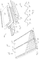
- FIG. 1 shows a roof forming element 1 in exploded view.
- Figure 5 shows a roof forming element 100.
- the roof forming elements 1, 100 and also other embodiments of roof forming elements described in the remainder of this description, are intended to be used for forming a roof of a building with a plurality of such elements. Said plurality of roof forming elements close an opening of the building of which the roof forms part. See figures 10a and 10b for examples of a roof 3, 103 according to the invention, during the construction process of the roof. At the left side of figures 10a, 10b a completed roof according to the invention, of a further building, is shown.
- the opening 6 of a building 2, at least in the examples of figures 10a and 10b , is defined by a front wall 4 and a ridge beam 9, and by two opposite side walls 5a and 5b.
- the roof 3, 103 is a pitched roof, extending from the front wall 4, or at least from a lower extremity, to a ridge 9, or at least a higher extremity, being supported by said walls 5a, 5b forming a support structure for the roof 3, 103.
- the opening 6 is free from any support elements such as rafters and purlins. In an embodiment, the opening may have one or more purlins, for the purpose of forming a connection between the side walls.
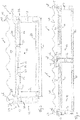
- Each of the roof forming elements comprises an elongate integral extruded combination 10 of a roof plate 11 and a beam 12.
- the roof plate 11 has a top plate 14 and a bottom plate 16 parallel to the top plate 14. See also figure 3 .
- the roof plate 11 further has an intermediate plate 20 between the top plate 14 and the bottom plate 16, wherein the intermediate plate 20 is integrally interconnected to the top plate 14 as well as to the bottom plate 16 via a plurality of ribs 21 and 22 respectively, extending in length direction 8, i.e. extrusion direction of the roof plate 11.
- the beam 12 extends in the length direction of the roof plate 11 and is located at a first longitudinal side 24 of the roof plate 11. It protrudes downwards from the bottom plate 16 of the roof plate, having a height h of 15 cm., at least in the present example.
- the width w of the roof plate 11 is 70 cm., at least in the present example.
- the ratio of height h : width w depends on the requirements of a specific roof to be formed using said roof forming element 1.
- a second longitudinal side 26 of the roof plate 11 is free from such a beam protruding downwards from the bottom plate.
- the integral combination 10 of the roof plate 11 and the beam 12 has an L-shaped cross-section.
- the roof forming element has a length I but may, in dependence of the relevant dimension of a building opening to be spanned, longer or shorter.
- the first longitudinal side 24 is provided with a groove 30 facing upwards, in the length direction.
- the second longitudinal side 26 has a rib 32 facing downwards, also in the length direction.
- the groove 30 and rib 32 are configured such that the rib 32 of a further roof forming element, being the same as the roof forming element 1, can be received in the groove 30 of the roof forming element 1, such that the roof forming element 1 supports said further element at that location. This means that the beam 12 of the roof forming element 1 also supports the roof plate of said further roof forming element.
- the roof forming element 1, more specifically said rib 32 and groove 30, is configured such that in coupled condition to a further, neighbouring roof forming element as described, the respective roof plates of said roof forming element 1 and said further roof forming elements are flush with respect to each other. See also figures 3 and 4 .
- Said groove 30 and rib 32 are part of coupling means for coupling the roof forming element to a further, neighbouring roof forming element.
- the roof forming element 1 also has a cover 40 for at least substantially completely covering the top plate 14 at a distance therefrom, so as to define an interior space 44 between the cover 40 and the top plate 14 closed from external influences.
- the cover 40 extends over the entire width of the roof plate 11 and over the length I of the roof plate 11.
- the cover 40 is corrugated and closes the interior space 44.
- the cover 40 protects the interior space 44 from external influences, such as precipitation, at the longitudinal sides of the roof forming element 1, wherein the roof forming element 1 may comprise a closing element (not shown) at both its end faces seen in the length direction, extending between the roof plate and the cover, for sealing the interior space of the roof forming element at the respective end face.
- a closing element not shown
- the cover has a wall portion 46 at a first longitudinal side 47.
- the wall portion 46 is received in a groove 49 at the second longitudinal side 26 of the roof forming element 1' disposed left from the element 1 the element 1, see figure 4 .
- the wall portion 46 may be received in a groove 49a of an end piece 13 in case element 1 is the most left element in a row of such elements, see figure 3 .
- the wall portion 46 of the cover 40 of a first one of the roof forming elements 1' supports the second longitudinal side 48 of the cover 40 of a further, neighbouring one 1 of the roof forming elements 1, 1'.
- FIG. 1 shows a connection between said two adjacent elements 1, 1' in a row of such elements.
- the end piece 15 supports the second longitudinal side 48 of the cover of element 1.
- the roof plate 11 of the roof forming element 1 has a rib 50 at the first longitudinal side 24 of the roof plate 11, on top of the top plate 14.
- the roof plate also has a flange element 52 at the second longitudinal side of the roof plate 11, which is arranged to overlap, or, hook over, the rib 50 of a further, neighbouring roof forming element coupled to the roof forming element 1.
- the integral combination 10 of the roof plate 11 and the beam 12 is at least substantially made of glass fibre reinforced polypropylene, preferably PP-LGF.
- the roof forming element 1 also comprises a photovoltaic element 60 in its interior space 44.
- the cover 40 is light transparent to such an extent that in use electrical power can be generated by the photovoltaic element 60 due to incident sunlight.
- the photovoltaic element 60 covers about the entire surface of the roof plate 11. Alternatively, part of said surface may be covered with a photovoltaic element.
- some or all of the plurality of roof forming elements forming the roof may not have a photovoltaic element.
- the amount of photovoltaic elements in the plurality of roof forming elements may be chosen based on for example the desired total combined amount of electrical energy to be generated by the photovoltaic elements.
- the roof forming elements 1 are configured to extend in one piece from the lower extremity to the higher extremity of an opening of the building in the absence of any other support structure in the opening.
- the beams 12 provide the required bending stiffness of the roof forming elements 1.
- the plurality of roof forming elements 1 are coupled to each other.
- the roof also comprises an additional roof element having the roof plate and the cover but being free from a beam at its first longitudinal side, which additional roof element is coupled to one of the outer ones of the mutually coupled roof forming elements at the first longitudinal side of that outer roof forming element, wherein the opening is closed entirely by the additional roof element and the plurality of roof forming elements.
- a roof formed from a plurality of elements 1 may comprise a plurality of ceiling plates 80, each covering the space between two neighbouring beams 12 of two respective neighbouring roof forming elements 1, being connected to a free end of said beams, preferably by means of a snap/lock connection.
- the ceiling plates are also extruded, at least in the present example.
- a ceiling is formed for an interior space of the building underneath the roof.
- insulation material 81 may be provided in said space between the ceiling panel 80 and the roof plate 11.
- the opening 6 is closed by a plurality of interconnected roof forming elements 1 each extending in vertical direction and spanning the opening 6 between the front wall 4, or at least the gutter, and the ridge 9.
- the elements 1 are partly shown.
- FIG. 5 shows a roof forming element 100 as an alternative embodiment of a roof forming element according to the invention.
- the roof forming element 100 is identical to the roof forming element 1, except for the cover 140 and for the end piece 115.
- Roof forming element 100 has a cover 140 also having a roof tile pattern, but now in width direction of the roof forming element 100. This means that a plurality of such elements 100 are to be provided in the building opening such that they extend in a horizontal direction.
- the end piece 115 is designed to follow the interior contour of the cover 140.
- the opening 6 is closed by a plurality of interconnected roof forming elements 100 each extending in horizontal direction and spanning the opening 6 between the side walls 5a, 5b.
- FIG. 7 shows two roof forming elements 200, 200', interconnected, which roof forming elements 200 are an alternative embodiment of roof forming elements according to the invention.
- the roof forming element 200, 200' is identical to the roof forming element 1, 100, except for the cover.
- Roof forming element 200, 200' has a cover 240 in the form of a glass plate being placed on top of the roof plate 11 such that it is at a distance in the range of about 1 mm. to about 5 cm. from the top plate 14. It defines an interior space 44 between the top plate 14 and the glass plate 240 in which interior space a photovoltaic element 60 is provided.
- the cover 240 is overlapped by the flange 52 element of a further, neighbouring roof forming element, as shown in figure 5 .
- the above mentioned groove 49 may be closed by a closing strip, or may be absent at all.
- Figure 8 and figure 9 show a part of an industrial roof 102 comprising a plurality of roof forming elements 200.
- the roof has a plurality of mutually identical, spaced apart support beams 190, made of a polymer such as polycarbonate. At least in the present example, the support beams are transparent to such an extent that daylight can pass trough the support beams to the interior of the building.
- the beams 190 are extruded and have a flat bottom portion 193, a first wall part 191 at the one longitudinal side and the second wall part 192 opposite the first wall part 191 at the other longitudinal side of the bottom portion 193.
- the first wall part 191 is of greater height and supports the beam 12 of a roof forming element.
- the second wall part 192 of a neighbouring support beam 190 supports that same roof forming element 200 at its second longitudinal side 26.
- the roof plate 11 of the roof forming element 200 is oriented under an angle with respect to the horizontal, or, with respect to the bottom plate 193 of the support beam 190.
- the beams 190 as well as the roof forming elements 200 preferably extend over the entire opening of the building covered by the roof 102.
- elements 100 may be used alternatively to or in combination with elements 200.
Landscapes
- Engineering & Computer Science (AREA)
- Architecture (AREA)
- Civil Engineering (AREA)
- Structural Engineering (AREA)
- Physics & Mathematics (AREA)
- Electromagnetism (AREA)
- Life Sciences & Earth Sciences (AREA)
- Sustainable Development (AREA)
- Sustainable Energy (AREA)
- Thermal Sciences (AREA)
- Chemical & Material Sciences (AREA)
- Combustion & Propulsion (AREA)
- Mechanical Engineering (AREA)
- General Engineering & Computer Science (AREA)
- Roof Covering Using Slabs Or Stiff Sheets (AREA)
Claims (15)
- Élément de formation de toit (1; 100) pour un toit (3; 103) d'un bâtiment (2), lequel toit ferme une ouverture (6) du bâtiment, dans lequel le toit (3; 103) est au moins partiellement formé par une pluralité de tels éléments de formation de toit (1; 100) qui ferment chacun une partie de ladite ouverture (6),
l'élément de formation de toit (1; 100) comprenant- une plaque de toit (11) allongée, de préférence extrudée, en polymère, comportant une plaque supérieure (14) et une plaque inférieure (16) parallèle à la plaque supérieure, lesquelles plaques supérieure et inférieure (14; 16) sont solidairement reliées par une pluralité de nervures (21, 22) s'étendant dans une direction longitudinale de la plaque de toit (11),- une poutre (12) qui est fabriquée, de préférence extrudée, comme partie intégrant de la plaque de toit (11), dans laquelle la poutre (12) s'étend dans la direction longitudinale (8) de la plaque de toit (11), est située sur un premier côté longitudinal (24) de la plaque de toit (11), et fait saillie vers le bas depuis la plaque inférieure (16) de la plaque de toit (11), l'autre côté longitudinal (26) étant exempt d'une telle poutre faisant saillie vers le bas depuis la plaque inférieure, de sorte que la combinaison intégrale (10) de la plaque de toit (11) et de la poutre (12) a une section transversale en forme de L,- un couvercle (40; 140) pour recouvrir au moins sensiblement complètement la plaque supérieure (14) à distance de celle-ci, de manière à définir un espace intérieur (44) entre le couvercle (40; 140) et la plaque supérieure (14), dans lequel le couvercle (40; 140) comprend au moins un élément de recouvrement qui s'étend sur la largeur entière de la plaque de toit (11) et sur au moins une partie de la longueur de la plaque de toit (11), et- des moyens de couplage (30, 32) pour coupler l'élément de formation de toit (1; 100) à un autre élément de formation de toit voisin (1'; 100') parmi ladite pluralité d'éléments de formation de toit,dans lequel l'élément de formation de toit (1; 100), au moins à l'état monté d'une pluralité de tels éléments de formation de toit (1; 100) formant le toit (3; 103), est configuré de telle sorte que le second côté longitudinal (26) de l'élément de formation de toit (1; 100) est agencé pour être supporté par le premier côté longitudinal d'un autre élément voisin (1'; 100') parmi ladite pluralité d'éléments de formation de toit, de sorte que la poutre de l'autre élément de formation de toit supporte également la plaque de toit (11) de l'élément de formation de toit (1; 100), et de sorte que les plaques de toit (11) respectives dudit élément de formation de plaques de toit (1; 100) et l'autre élément de formation de toit (1'; 100') soient au même niveau l'un par rapport à l'autre. - Élément de formation de toit (1; 100) selon la revendication 1, dans lequel le rapport entre la hauteur (h) de la poutre (12) et la largeur (W) de la plaque de toit (11) est compris entre 1:15 et 1:1, de préférence entre 1:10 et 1:2, idéalement entre 1:8 et 1:3.
- Élément de formation de toit (1; 100) selon l'une quelconque des revendications précédentes, dans lequel les moyens de couplage (30, 32) sont configurés pour un couplage, de préférence un couplage par complémentarité, du second côté longitudinal (26) de l'élément de formation de toit (1; 100) à un premier côté longitudinal de l'autre élément voisin (1'; 100') parmi la pluralité d'éléments de formation de toit.
- Élément de formation de toit (1; 100) selon la revendication 3, dans lequel la plaque de toit (11) présente une nervure (50) sur le premier côté longitudinal (24) de la plaque de toit (11), sur la plaque supérieure (14) de la plaque de toit (11), et présente sur le second côté longitudinal (26) de la plaque de toit (11) un élément de bride (52) qui est disposé de manière à recouvrir une nervure de l'autre élément de formation de toit voisin (1'; 100') relié à l'élément de formation de toit (1; 100).
- Élément de formation de toit (1; 100) selon l'une quelconque des revendications précédentes, dans lequel la plaque de toit comprend une plaque intermédiaire (20) entre la plaque supérieure (14) et la plaque inférieure (16), dans lequel la plaque intermédiaire (20) est solidairement reliée à la plaque supérieure (14) ainsi qu'à la plaque inférieure (16) via une pluralité de nervures (21, 22) s'étendant dans la direction longitudinale (8) de la plaque de toit (11).
- Élément de formation de toit (1; 100) selon l'une quelconque des revendications précédentes, dans lequel le couvercle (40) scelle hermétiquement l'espace intérieur (44) par l'extérieur sur les côtés longitudinaux (24; 26) de l'élément de formation de toit (1; 100), l'élément de formation de toit (1; 100) comprenant sur ses deux faces d'extrémité dans la direction longitudinale (8), un élément de fermeture respectif s'étendant entre la plaque de toit (11) et le couvercle (40) pour sceller hermétiquement l'espace intérieur (44) de l'élément de formation de toit (1; 100) à la face d'extrémité respective.
- Élément de formation de toit (1; 100) selon l'une quelconque des revendications précédentes, dans lequel la combinaison intégrale (10) de la plaque de toit (11) et de la poutre (12) est au moins essentiellement constituée d'un polymère, dans lequel le polymère est de préférence une polyoléfine, de préférence du polypropylène ou du polyéthylène, dans lequel le polymère est en outre de préférence un polymère renforcé, de préférence un polymère renforcé de fibres de verre, de préférence du polypropylène renforcé de fibres de verre.
- Élément de formation de toit (1; 100) selon l'une quelconque des revendications précédentes, comprenant un élément photovoltaïque (60) dans son espace intérieur (44), dans lequel le couvercle (40) est transparent à la lumière dans une mesure telle qu'en utilisation, l'énergie électrique est produite par l'élément photovoltaïque (60) grâce à la lumière solaire incidente.
- Toit (3; 103) d'un bâtiment (2), le toit (3; 103) fermant une ouverture (6) du bâtiment (2), le toit (3; 103) étant au moins partiellement formé par une pluralité d'éléments de formation de toit (1; 100) selon l'une quelconque des revendications précédentes, lesquels éléments ferment chacun une partie de ladite ouverture (6), la pluralité d'éléments de formation de toit (1; 100) étant supportée par une structure de support du bâtiment (2), ladite structure de support entourant l'ouverture (6).
- Toit (3; 103) selon la revendication 9, le toit (3; 103) étant conçu de telle sorte qu'en utilisation, le second côté longitudinal (26) d'un premier élément (1; 100) parmi ladite pluralité d'éléments de formation de toit est supporté par le premier côté longitudinal d'un second élément voisin (1'; 100') parmi ladite pluralité d'éléments de formation de toit, de sorte que la poutre du second élément de formation de toit supporte également la plaque de toit (11) dudit premier élément de formation de toit (1; 100), et les plaques de toit respectives (11) desdits premier et second éléments de formation de toit étant au même niveau l'une par rapport à l'autre.
- Toit (3) selon la revendication 10, comprenant en outre une pluralité de plaques de plafond (80), dans lequel chacune des plaques de plafond (80) est reliée à une extrémité libre de la poutre (12) d'au moins deux éléments de formation de toit voisins, de manière à former un plafond pour un espace intérieur du bâtiment (2) sous le toit (3; 103).
- Toit (3; 103) selon la revendication 10 ou 11, dans lequel chacun de la pluralité d'éléments de formation de toit a une longueur qui est environ égale à une longueur du toit (3; 103) et chacun présente une largeur qui fait partie d'une largeur du toit (3; 103), dans lequel la pluralité d'éléments de formation de toit sont interconnectés de manière à fermer l'ouverture (6) entière dans le bâtiment (2).
- Toit (3; 103) selon la revendication 10, 11 ou 12, dans lequel chacun de la pluralité d'éléments de formation de toit a une longueur qui est environ égale à une longueur du toit (3; 103) et chacun présente une largeur qui fait partie d'une largeur du toit (3; 103), dans lequel la pluralité d'éléments de formation de toit sont interconnectés, le toit (3; 103) comprenant également un autre élément de formation de toit ayant la plaque de toit et le couvercle mais qui est exempt d'une poutre sur son premier côté longitudinal, lequel autre élément de formation de toit est interconnecté à un élément parmi les éléments extérieurs de formation de toit interconnectés (1; 100) sur le premier côté longitudinal (24) de cet élément extérieur de formation de toit, l'ouverture (6) étant entièrement fermée par l'autre élément de formation de toit et par la pluralité d'éléments de formation de toit.
- Toit (3; 103) selon l'une quelconque des revendications 9 à 13, le toit (3; 103) étant un toit incliné, dans lequel l'ouverture (6) fermée par le toit (3; 103) est délimitée par un rebord (9) et une paroi du bâtiment (4) qui définissent la longueur du toit (3; 103), et par d'autres parois de bâtiment opposées (5a, 5b) qui définissent une largeur du toit (3; 103).
- Toit (3) selon l'une quelconque des revendications 9 à 14, comprenant dans l'espace intérieur (44) de l'au moins un de la pluralité d'éléments de formation de toit un élément photovoltaïque (60), dans lequel le couvercle (40) de cet au moins un élément de formation de toit est transparent à la lumière dans une mesure telle qu'en utilisation, l'énergie électrique est produite par l'élément photovoltaïque (60) grâce à la lumière solaire incidente.
Applications Claiming Priority (2)
| Application Number | Priority Date | Filing Date | Title |
|---|---|---|---|
| EP15183470 | 2015-09-02 | ||
| PCT/EP2016/070684 WO2017037214A1 (fr) | 2015-09-02 | 2016-09-02 | Élément de formation de toit pour un toit de bâtiment, et toit |
Publications (2)
| Publication Number | Publication Date |
|---|---|
| EP3344824A1 EP3344824A1 (fr) | 2018-07-11 |
| EP3344824B1 true EP3344824B1 (fr) | 2019-10-23 |
Family
ID=54064144
Family Applications (1)
| Application Number | Title | Priority Date | Filing Date |
|---|---|---|---|
| EP16760467.7A Active EP3344824B1 (fr) | 2015-09-02 | 2016-09-02 | Élément de formation de toit pour le toit d'un bâtiment et toit |
Country Status (4)
| Country | Link |
|---|---|
| US (1) | US10626604B2 (fr) |
| EP (1) | EP3344824B1 (fr) |
| CN (1) | CN108350691B (fr) |
| WO (1) | WO2017037214A1 (fr) |
Families Citing this family (1)
| Publication number | Priority date | Publication date | Assignee | Title |
|---|---|---|---|---|
| JP6692375B2 (ja) * | 2015-12-09 | 2020-05-13 | 株式会社カネカ | 太陽電池モジュール及び屋根構造 |
Family Cites Families (26)
| Publication number | Priority date | Publication date | Assignee | Title |
|---|---|---|---|---|
| DE1931322U (de) | 1965-10-21 | 1966-01-20 | Leichtdach Bau & Montage Ges | Plattenfoermiges dach- und wandelement mit traggliedern. |
| FR1581692A (fr) | 1968-07-16 | 1969-09-19 | ||
| DE2532853C2 (de) | 1975-07-23 | 1990-03-29 | Neumann & Co AG, 9470 Buchs | Unterdach für mit Dacheindeckungsplatten eingedeckte Dächer |
| IL61314A (en) | 1980-10-20 | 1984-06-29 | Dan Pal Tech Plastic Ind | Light-transmitting wall panels |
| DK150585C (da) * | 1983-09-30 | 1987-10-05 | Villadsens Fab As Jens | Kasseformet byggeelement og tagkonstruktion opbygget af saadanne elementer |
| US5177924A (en) * | 1986-12-03 | 1993-01-12 | Stefan Kakuk | Lightweight building component |
| US4930282A (en) * | 1988-01-26 | 1990-06-05 | Meadows David F | Architectural tile |
| ZA929791B (en) * | 1991-12-19 | 1993-09-16 | Knudson Gary Art | Building and method and apparatus for making panel assemblies and connecting apparatus |
| CA2089025A1 (fr) * | 1993-02-08 | 1994-08-09 | Vittorio De Zen | Bardage moule destine a des batiments |
| US5768831A (en) * | 1993-09-16 | 1998-06-23 | Blue Planet Ag | Rooftile support for photocell panel |
| US5613339A (en) * | 1993-12-01 | 1997-03-25 | Heritage Vinyl Products, Inc. | Deck plank and cover |
| US5411782A (en) * | 1993-12-20 | 1995-05-02 | Jarvis; Barry M. | Interfitting plastic panels |
| DE4416027C2 (de) | 1994-05-06 | 1998-02-19 | Goetz Peter Dipl Ing Fh | Leichtbauplatte |
| US5758456A (en) * | 1996-12-04 | 1998-06-02 | Royal Plastics Group | Deck plank |
| US6023922A (en) | 1997-07-28 | 2000-02-15 | Ultraframe Plc Of Enterprise Works | Glazed structures |
| JP2002167906A (ja) * | 2000-11-28 | 2002-06-11 | Shinodaya:Kk | 瓦、瓦固定釘および瓦葺き工法 |
| GB2429742B (en) | 2003-06-17 | 2008-01-23 | Naturalight Systems Ltd | A glazing system |
| USD505497S1 (en) * | 2004-03-29 | 2005-05-24 | Lifetime Products, Inc. | Exterior surface of a shed |
| GB2413808B (en) | 2004-05-07 | 2009-05-06 | Kingspan Res & Dev Ltd | A translucent roof panel |
| US8065841B2 (en) | 2006-12-29 | 2011-11-29 | Antonic James P | Roof panel systems for building construction |
| US8945699B2 (en) * | 2008-11-03 | 2015-02-03 | Sabic Global Technologies B.V. | Sheet, an article, and a method of making a sheet |
| US20120186633A1 (en) * | 2009-11-05 | 2012-07-26 | James Carolan | Composite insulating panel |
| US8397447B2 (en) * | 2010-04-15 | 2013-03-19 | Eco Solar Generation Llc | Roof truss compatible for solar panels |
| US20120011798A1 (en) * | 2010-07-16 | 2012-01-19 | Ernest Rivellino | Building system and components therefor |
| CA2794182A1 (fr) * | 2011-11-14 | 2013-05-14 | Certainteed Corporation | Composantes de toiture photovoltaique et systemes |
| US9312411B2 (en) * | 2012-04-26 | 2016-04-12 | Sabic Global Technologies B.V. | Connector assemblies for connecting panels, panels with connector assemblies |
-
2016
- 2016-09-02 WO PCT/EP2016/070684 patent/WO2017037214A1/fr not_active Ceased
- 2016-09-02 CN CN201680061442.4A patent/CN108350691B/zh active Active
- 2016-09-02 EP EP16760467.7A patent/EP3344824B1/fr active Active
- 2016-09-02 US US15/756,175 patent/US10626604B2/en active Active
Non-Patent Citations (1)
| Title |
|---|
| None * |
Also Published As
| Publication number | Publication date |
|---|---|
| US10626604B2 (en) | 2020-04-21 |
| WO2017037214A1 (fr) | 2017-03-09 |
| EP3344824A1 (fr) | 2018-07-11 |
| CN108350691A (zh) | 2018-07-31 |
| CN108350691B (zh) | 2020-10-16 |
| US20180245343A1 (en) | 2018-08-30 |
Similar Documents
| Publication | Publication Date | Title |
|---|---|---|
| US8800221B1 (en) | Vertical and sloped glazing framing members structured for electrical wiring | |
| EP0619404B1 (fr) | Panneau de toit avec batteries solaires et structure de toit avec batteries solaires | |
| US20080000174A1 (en) | Profile roof tile with integrated photovoltaic module | |
| EP2707556B1 (fr) | Système de toiture modulaire pour bâtiment | |
| KR102260055B1 (ko) | 배수 기능이 구비된 천장 일체형 태양광 발전 지붕 구조 | |
| WO2009141809A2 (fr) | Unité modulaire de création de structures porteuses servant de construction et/ou de support pour un tapis solaire | |
| KR101640195B1 (ko) | 전선배관 일체형 단열 비노출형 커튼월 시스템 | |
| US20120240485A1 (en) | Panel construction system | |
| ES2582506T3 (es) | Un bloque de vidrio integrado de células solares híbridas y un panel pretensado hecho de bloques de vidrio ensamblados en seco para la construcción de cerramientos translúcidos de edificios | |
| US10662649B2 (en) | Prefabricated construction device, setting in place and usage thereof | |
| EP3344824B1 (fr) | Élément de formation de toit pour le toit d'un bâtiment et toit | |
| EP2072708B1 (fr) | Structure de panneau pour toits et similaires | |
| US11155997B2 (en) | Roof forming element, roof, and method of manufacturing | |
| US6161356A (en) | Building elements | |
| CA2860242C (fr) | Elements d'encadrement de vitrage inclines et verticaux structures pour le cablage electrique | |
| EP3563014B1 (fr) | Élément de formation de toit solaire et bâtiment | |
| WO1981003675A1 (fr) | Panneaux destines a etre utilises dans la toiture et les parois de batiments | |
| KR100984587B1 (ko) | 복층 채광판 | |
| CN203412224U (zh) | 太阳能电池屋顶构造 | |
| EP1286007A1 (fr) | Vitrage avec efficience thermique | |
| JPH1162144A (ja) | 太陽電池付き屋根 | |
| TWI625455B (zh) | 多功能保溫片及架設結構 | |
| CN121443815A (zh) | 建筑围护结构覆盖系统及组件 | |
| JP2003096999A (ja) | 屋 根 | |
| ITMI20100104U1 (it) | Struttura di copertura per impianti sportivi |
Legal Events
| Date | Code | Title | Description |
|---|---|---|---|
| STAA | Information on the status of an ep patent application or granted ep patent |
Free format text: STATUS: UNKNOWN |
|
| STAA | Information on the status of an ep patent application or granted ep patent |
Free format text: STATUS: THE INTERNATIONAL PUBLICATION HAS BEEN MADE |
|
| PUAI | Public reference made under article 153(3) epc to a published international application that has entered the european phase |
Free format text: ORIGINAL CODE: 0009012 |
|
| STAA | Information on the status of an ep patent application or granted ep patent |
Free format text: STATUS: REQUEST FOR EXAMINATION WAS MADE |
|
| 17P | Request for examination filed |
Effective date: 20180223 |
|
| AK | Designated contracting states |
Kind code of ref document: A1 Designated state(s): AL AT BE BG CH CY CZ DE DK EE ES FI FR GB GR HR HU IE IS IT LI LT LU LV MC MK MT NL NO PL PT RO RS SE SI SK SM TR |
|
| AX | Request for extension of the european patent |
Extension state: BA ME |
|
| DAV | Request for validation of the european patent (deleted) | ||
| DAX | Request for extension of the european patent (deleted) | ||
| GRAP | Despatch of communication of intention to grant a patent |
Free format text: ORIGINAL CODE: EPIDOSNIGR1 |
|
| STAA | Information on the status of an ep patent application or granted ep patent |
Free format text: STATUS: GRANT OF PATENT IS INTENDED |
|
| INTG | Intention to grant announced |
Effective date: 20190320 |
|
| GRAS | Grant fee paid |
Free format text: ORIGINAL CODE: EPIDOSNIGR3 |
|
| GRAA | (expected) grant |
Free format text: ORIGINAL CODE: 0009210 |
|
| STAA | Information on the status of an ep patent application or granted ep patent |
Free format text: STATUS: THE PATENT HAS BEEN GRANTED |
|
| AK | Designated contracting states |
Kind code of ref document: B1 Designated state(s): AL AT BE BG CH CY CZ DE DK EE ES FI FR GB GR HR HU IE IS IT LI LT LU LV MC MK MT NL NO PL PT RO RS SE SI SK SM TR |
|
| REG | Reference to a national code |
Ref country code: GB Ref legal event code: FG4D |
|
| REG | Reference to a national code |
Ref country code: CH Ref legal event code: EP |
|
| REG | Reference to a national code |
Ref country code: IE Ref legal event code: FG4D |
|
| REG | Reference to a national code |
Ref country code: DE Ref legal event code: R096 Ref document number: 602016022968 Country of ref document: DE |
|
| REG | Reference to a national code |
Ref country code: AT Ref legal event code: REF Ref document number: 1193776 Country of ref document: AT Kind code of ref document: T Effective date: 20191115 |
|
| REG | Reference to a national code |
Ref country code: NL Ref legal event code: FP |
|
| REG | Reference to a national code |
Ref country code: LT Ref legal event code: MG4D |
|
| PG25 | Lapsed in a contracting state [announced via postgrant information from national office to epo] |
Ref country code: PL Free format text: LAPSE BECAUSE OF FAILURE TO SUBMIT A TRANSLATION OF THE DESCRIPTION OR TO PAY THE FEE WITHIN THE PRESCRIBED TIME-LIMIT Effective date: 20191023 Ref country code: NO Free format text: LAPSE BECAUSE OF FAILURE TO SUBMIT A TRANSLATION OF THE DESCRIPTION OR TO PAY THE FEE WITHIN THE PRESCRIBED TIME-LIMIT Effective date: 20200123 Ref country code: GR Free format text: LAPSE BECAUSE OF FAILURE TO SUBMIT A TRANSLATION OF THE DESCRIPTION OR TO PAY THE FEE WITHIN THE PRESCRIBED TIME-LIMIT Effective date: 20200124 Ref country code: PT Free format text: LAPSE BECAUSE OF FAILURE TO SUBMIT A TRANSLATION OF THE DESCRIPTION OR TO PAY THE FEE WITHIN THE PRESCRIBED TIME-LIMIT Effective date: 20200224 Ref country code: BG Free format text: LAPSE BECAUSE OF FAILURE TO SUBMIT A TRANSLATION OF THE DESCRIPTION OR TO PAY THE FEE WITHIN THE PRESCRIBED TIME-LIMIT Effective date: 20200123 Ref country code: FI Free format text: LAPSE BECAUSE OF FAILURE TO SUBMIT A TRANSLATION OF THE DESCRIPTION OR TO PAY THE FEE WITHIN THE PRESCRIBED TIME-LIMIT Effective date: 20191023 Ref country code: LT Free format text: LAPSE BECAUSE OF FAILURE TO SUBMIT A TRANSLATION OF THE DESCRIPTION OR TO PAY THE FEE WITHIN THE PRESCRIBED TIME-LIMIT Effective date: 20191023 Ref country code: SE Free format text: LAPSE BECAUSE OF FAILURE TO SUBMIT A TRANSLATION OF THE DESCRIPTION OR TO PAY THE FEE WITHIN THE PRESCRIBED TIME-LIMIT Effective date: 20191023 Ref country code: LV Free format text: LAPSE BECAUSE OF FAILURE TO SUBMIT A TRANSLATION OF THE DESCRIPTION OR TO PAY THE FEE WITHIN THE PRESCRIBED TIME-LIMIT Effective date: 20191023 |
|
| PG25 | Lapsed in a contracting state [announced via postgrant information from national office to epo] |
Ref country code: RS Free format text: LAPSE BECAUSE OF FAILURE TO SUBMIT A TRANSLATION OF THE DESCRIPTION OR TO PAY THE FEE WITHIN THE PRESCRIBED TIME-LIMIT Effective date: 20191023 Ref country code: IS Free format text: LAPSE BECAUSE OF FAILURE TO SUBMIT A TRANSLATION OF THE DESCRIPTION OR TO PAY THE FEE WITHIN THE PRESCRIBED TIME-LIMIT Effective date: 20200224 Ref country code: HR Free format text: LAPSE BECAUSE OF FAILURE TO SUBMIT A TRANSLATION OF THE DESCRIPTION OR TO PAY THE FEE WITHIN THE PRESCRIBED TIME-LIMIT Effective date: 20191023 |
|
| PG25 | Lapsed in a contracting state [announced via postgrant information from national office to epo] |
Ref country code: AL Free format text: LAPSE BECAUSE OF FAILURE TO SUBMIT A TRANSLATION OF THE DESCRIPTION OR TO PAY THE FEE WITHIN THE PRESCRIBED TIME-LIMIT Effective date: 20191023 |
|
| REG | Reference to a national code |
Ref country code: DE Ref legal event code: R097 Ref document number: 602016022968 Country of ref document: DE |
|
| PG2D | Information on lapse in contracting state deleted |
Ref country code: IS |
|
| PG25 | Lapsed in a contracting state [announced via postgrant information from national office to epo] |
Ref country code: IS Free format text: LAPSE BECAUSE OF FAILURE TO SUBMIT A TRANSLATION OF THE DESCRIPTION OR TO PAY THE FEE WITHIN THE PRESCRIBED TIME-LIMIT Effective date: 20200223 Ref country code: EE Free format text: LAPSE BECAUSE OF FAILURE TO SUBMIT A TRANSLATION OF THE DESCRIPTION OR TO PAY THE FEE WITHIN THE PRESCRIBED TIME-LIMIT Effective date: 20191023 Ref country code: DK Free format text: LAPSE BECAUSE OF FAILURE TO SUBMIT A TRANSLATION OF THE DESCRIPTION OR TO PAY THE FEE WITHIN THE PRESCRIBED TIME-LIMIT Effective date: 20191023 Ref country code: ES Free format text: LAPSE BECAUSE OF FAILURE TO SUBMIT A TRANSLATION OF THE DESCRIPTION OR TO PAY THE FEE WITHIN THE PRESCRIBED TIME-LIMIT Effective date: 20191023 Ref country code: CZ Free format text: LAPSE BECAUSE OF FAILURE TO SUBMIT A TRANSLATION OF THE DESCRIPTION OR TO PAY THE FEE WITHIN THE PRESCRIBED TIME-LIMIT Effective date: 20191023 Ref country code: RO Free format text: LAPSE BECAUSE OF FAILURE TO SUBMIT A TRANSLATION OF THE DESCRIPTION OR TO PAY THE FEE WITHIN THE PRESCRIBED TIME-LIMIT Effective date: 20191023 |
|
| REG | Reference to a national code |
Ref country code: AT Ref legal event code: MK05 Ref document number: 1193776 Country of ref document: AT Kind code of ref document: T Effective date: 20191023 |
|
| PLBE | No opposition filed within time limit |
Free format text: ORIGINAL CODE: 0009261 |
|
| STAA | Information on the status of an ep patent application or granted ep patent |
Free format text: STATUS: NO OPPOSITION FILED WITHIN TIME LIMIT |
|
| PG25 | Lapsed in a contracting state [announced via postgrant information from national office to epo] |
Ref country code: SM Free format text: LAPSE BECAUSE OF FAILURE TO SUBMIT A TRANSLATION OF THE DESCRIPTION OR TO PAY THE FEE WITHIN THE PRESCRIBED TIME-LIMIT Effective date: 20191023 Ref country code: IT Free format text: LAPSE BECAUSE OF FAILURE TO SUBMIT A TRANSLATION OF THE DESCRIPTION OR TO PAY THE FEE WITHIN THE PRESCRIBED TIME-LIMIT Effective date: 20191023 Ref country code: SK Free format text: LAPSE BECAUSE OF FAILURE TO SUBMIT A TRANSLATION OF THE DESCRIPTION OR TO PAY THE FEE WITHIN THE PRESCRIBED TIME-LIMIT Effective date: 20191023 |
|
| 26N | No opposition filed |
Effective date: 20200724 |
|
| PG25 | Lapsed in a contracting state [announced via postgrant information from national office to epo] |
Ref country code: AT Free format text: LAPSE BECAUSE OF FAILURE TO SUBMIT A TRANSLATION OF THE DESCRIPTION OR TO PAY THE FEE WITHIN THE PRESCRIBED TIME-LIMIT Effective date: 20191023 Ref country code: SI Free format text: LAPSE BECAUSE OF FAILURE TO SUBMIT A TRANSLATION OF THE DESCRIPTION OR TO PAY THE FEE WITHIN THE PRESCRIBED TIME-LIMIT Effective date: 20191023 |
|
| REG | Reference to a national code |
Ref country code: CH Ref legal event code: PL |
|
| GBPC | Gb: european patent ceased through non-payment of renewal fee |
Effective date: 20200902 |
|
| PG25 | Lapsed in a contracting state [announced via postgrant information from national office to epo] |
Ref country code: LU Free format text: LAPSE BECAUSE OF NON-PAYMENT OF DUE FEES Effective date: 20200902 |
|
| PG25 | Lapsed in a contracting state [announced via postgrant information from national office to epo] |
Ref country code: CH Free format text: LAPSE BECAUSE OF NON-PAYMENT OF DUE FEES Effective date: 20200930 Ref country code: IE Free format text: LAPSE BECAUSE OF NON-PAYMENT OF DUE FEES Effective date: 20200902 Ref country code: GB Free format text: LAPSE BECAUSE OF NON-PAYMENT OF DUE FEES Effective date: 20200902 Ref country code: LI Free format text: LAPSE BECAUSE OF NON-PAYMENT OF DUE FEES Effective date: 20200930 |
|
| PG25 | Lapsed in a contracting state [announced via postgrant information from national office to epo] |
Ref country code: MT Free format text: LAPSE BECAUSE OF FAILURE TO SUBMIT A TRANSLATION OF THE DESCRIPTION OR TO PAY THE FEE WITHIN THE PRESCRIBED TIME-LIMIT Effective date: 20191023 Ref country code: CY Free format text: LAPSE BECAUSE OF FAILURE TO SUBMIT A TRANSLATION OF THE DESCRIPTION OR TO PAY THE FEE WITHIN THE PRESCRIBED TIME-LIMIT Effective date: 20191023 |
|
| PG25 | Lapsed in a contracting state [announced via postgrant information from national office to epo] |
Ref country code: MK Free format text: LAPSE BECAUSE OF FAILURE TO SUBMIT A TRANSLATION OF THE DESCRIPTION OR TO PAY THE FEE WITHIN THE PRESCRIBED TIME-LIMIT Effective date: 20191023 Ref country code: MC Free format text: LAPSE BECAUSE OF FAILURE TO SUBMIT A TRANSLATION OF THE DESCRIPTION OR TO PAY THE FEE WITHIN THE PRESCRIBED TIME-LIMIT Effective date: 20191023 |
|
| P01 | Opt-out of the competence of the unified patent court (upc) registered |
Effective date: 20230529 |
|
| PGFP | Annual fee paid to national office [announced via postgrant information from national office to epo] |
Ref country code: DE Payment date: 20250929 Year of fee payment: 10 |
|
| PGFP | Annual fee paid to national office [announced via postgrant information from national office to epo] |
Ref country code: TR Payment date: 20250822 Year of fee payment: 10 Ref country code: NL Payment date: 20250926 Year of fee payment: 10 |
|
| PGFP | Annual fee paid to national office [announced via postgrant information from national office to epo] |
Ref country code: BE Payment date: 20250929 Year of fee payment: 10 |
|
| PGFP | Annual fee paid to national office [announced via postgrant information from national office to epo] |
Ref country code: FR Payment date: 20250925 Year of fee payment: 10 |