EP3344925B1 - Procédé et système de fonctionnement d'échangeur d'énergie thermique - Google Patents
Procédé et système de fonctionnement d'échangeur d'énergie thermique Download PDFInfo
- Publication number
- EP3344925B1 EP3344925B1 EP16751208.6A EP16751208A EP3344925B1 EP 3344925 B1 EP3344925 B1 EP 3344925B1 EP 16751208 A EP16751208 A EP 16751208A EP 3344925 B1 EP3344925 B1 EP 3344925B1
- Authority
- EP
- European Patent Office
- Prior art keywords
- thermal energy
- thermal
- energy exchanger
- air
- normalized
- Prior art date
- Legal status (The legal status is an assumption and is not a legal conclusion. Google has not performed a legal analysis and makes no representation as to the accuracy of the status listed.)
- Active
Links
Images




Classifications
-
- F—MECHANICAL ENGINEERING; LIGHTING; HEATING; WEAPONS; BLASTING
- F24—HEATING; RANGES; VENTILATING
- F24F—AIR-CONDITIONING; AIR-HUMIDIFICATION; VENTILATION; USE OF AIR CURRENTS FOR SCREENING
- F24F11/00—Control or safety arrangements
- F24F11/30—Control or safety arrangements for purposes related to the operation of the system, e.g. for safety or monitoring
-
- F—MECHANICAL ENGINEERING; LIGHTING; HEATING; WEAPONS; BLASTING
- F24—HEATING; RANGES; VENTILATING
- F24F—AIR-CONDITIONING; AIR-HUMIDIFICATION; VENTILATION; USE OF AIR CURRENTS FOR SCREENING
- F24F11/00—Control or safety arrangements
- F24F11/30—Control or safety arrangements for purposes related to the operation of the system, e.g. for safety or monitoring
- F24F11/46—Improving electric energy efficiency or saving
-
- F—MECHANICAL ENGINEERING; LIGHTING; HEATING; WEAPONS; BLASTING
- F24—HEATING; RANGES; VENTILATING
- F24F—AIR-CONDITIONING; AIR-HUMIDIFICATION; VENTILATION; USE OF AIR CURRENTS FOR SCREENING
- F24F11/00—Control or safety arrangements
- F24F11/50—Control or safety arrangements characterised by user interfaces or communication
- F24F11/56—Remote control
- F24F11/58—Remote control using Internet communication
-
- F—MECHANICAL ENGINEERING; LIGHTING; HEATING; WEAPONS; BLASTING
- F24—HEATING; RANGES; VENTILATING
- F24F—AIR-CONDITIONING; AIR-HUMIDIFICATION; VENTILATION; USE OF AIR CURRENTS FOR SCREENING
- F24F11/00—Control or safety arrangements
- F24F11/62—Control or safety arrangements characterised by the type of control or by internal processing, e.g. using fuzzy logic, adaptive control or estimation of values
-
- F—MECHANICAL ENGINEERING; LIGHTING; HEATING; WEAPONS; BLASTING
- F24—HEATING; RANGES; VENTILATING
- F24F—AIR-CONDITIONING; AIR-HUMIDIFICATION; VENTILATION; USE OF AIR CURRENTS FOR SCREENING
- F24F11/00—Control or safety arrangements
- F24F11/62—Control or safety arrangements characterised by the type of control or by internal processing, e.g. using fuzzy logic, adaptive control or estimation of values
- F24F11/63—Electronic processing
-
- F—MECHANICAL ENGINEERING; LIGHTING; HEATING; WEAPONS; BLASTING
- F24—HEATING; RANGES; VENTILATING
- F24F—AIR-CONDITIONING; AIR-HUMIDIFICATION; VENTILATION; USE OF AIR CURRENTS FOR SCREENING
- F24F11/00—Control or safety arrangements
- F24F11/62—Control or safety arrangements characterised by the type of control or by internal processing, e.g. using fuzzy logic, adaptive control or estimation of values
- F24F11/63—Electronic processing
- F24F11/64—Electronic processing using pre-stored data
-
- F—MECHANICAL ENGINEERING; LIGHTING; HEATING; WEAPONS; BLASTING
- F24—HEATING; RANGES; VENTILATING
- F24F—AIR-CONDITIONING; AIR-HUMIDIFICATION; VENTILATION; USE OF AIR CURRENTS FOR SCREENING
- F24F11/00—Control or safety arrangements
- F24F11/62—Control or safety arrangements characterised by the type of control or by internal processing, e.g. using fuzzy logic, adaptive control or estimation of values
- F24F11/63—Electronic processing
- F24F11/65—Electronic processing for selecting an operating mode
-
- F—MECHANICAL ENGINEERING; LIGHTING; HEATING; WEAPONS; BLASTING
- F24—HEATING; RANGES; VENTILATING
- F24F—AIR-CONDITIONING; AIR-HUMIDIFICATION; VENTILATION; USE OF AIR CURRENTS FOR SCREENING
- F24F11/00—Control or safety arrangements
- F24F11/70—Control systems characterised by their outputs; Constructional details thereof
- F24F11/72—Control systems characterised by their outputs; Constructional details thereof for controlling the supply of treated air, e.g. its pressure
- F24F11/74—Control systems characterised by their outputs; Constructional details thereof for controlling the supply of treated air, e.g. its pressure for controlling air flow rate or air velocity
-
- F—MECHANICAL ENGINEERING; LIGHTING; HEATING; WEAPONS; BLASTING
- F24—HEATING; RANGES; VENTILATING
- F24F—AIR-CONDITIONING; AIR-HUMIDIFICATION; VENTILATION; USE OF AIR CURRENTS FOR SCREENING
- F24F11/00—Control or safety arrangements
- F24F11/70—Control systems characterised by their outputs; Constructional details thereof
- F24F11/80—Control systems characterised by their outputs; Constructional details thereof for controlling the temperature of the supplied air
- F24F11/83—Control systems characterised by their outputs; Constructional details thereof for controlling the temperature of the supplied air by controlling the supply of heat-exchange fluids to heat-exchangers
- F24F11/84—Control systems characterised by their outputs; Constructional details thereof for controlling the temperature of the supplied air by controlling the supply of heat-exchange fluids to heat-exchangers using valves
-
- G—PHYSICS
- G05—CONTROLLING; REGULATING
- G05B—CONTROL OR REGULATING SYSTEMS IN GENERAL; FUNCTIONAL ELEMENTS OF SUCH SYSTEMS; MONITORING OR TESTING ARRANGEMENTS FOR SUCH SYSTEMS OR ELEMENTS
- G05B17/00—Systems involving the use of models or simulators of said systems
- G05B17/02—Systems involving the use of models or simulators of said systems electric
-
- F—MECHANICAL ENGINEERING; LIGHTING; HEATING; WEAPONS; BLASTING
- F24—HEATING; RANGES; VENTILATING
- F24F—AIR-CONDITIONING; AIR-HUMIDIFICATION; VENTILATION; USE OF AIR CURRENTS FOR SCREENING
- F24F2110/00—Control inputs relating to air properties
- F24F2110/10—Temperature
-
- F—MECHANICAL ENGINEERING; LIGHTING; HEATING; WEAPONS; BLASTING
- F24—HEATING; RANGES; VENTILATING
- F24F—AIR-CONDITIONING; AIR-HUMIDIFICATION; VENTILATION; USE OF AIR CURRENTS FOR SCREENING
- F24F2110/00—Control inputs relating to air properties
- F24F2110/30—Velocity
-
- F—MECHANICAL ENGINEERING; LIGHTING; HEATING; WEAPONS; BLASTING
- F24—HEATING; RANGES; VENTILATING
- F24F—AIR-CONDITIONING; AIR-HUMIDIFICATION; VENTILATION; USE OF AIR CURRENTS FOR SCREENING
- F24F2140/00—Control inputs relating to system states
-
- F—MECHANICAL ENGINEERING; LIGHTING; HEATING; WEAPONS; BLASTING
- F24—HEATING; RANGES; VENTILATING
- F24F—AIR-CONDITIONING; AIR-HUMIDIFICATION; VENTILATION; USE OF AIR CURRENTS FOR SCREENING
- F24F2140/00—Control inputs relating to system states
- F24F2140/20—Heat-exchange fluid temperature
Definitions
- the present invention relates to a method and a control system for operating a thermal energy exchanger. Specifically, the present invention relates to a method and a control system for operating a thermal energy exchanger of an HVAC (Heating, Ventilating, and Air Conditioning) system for exchanging thermal energy between a thermal transfer fluid, flowing through the thermal energy exchanger in a fluid conduit, and air, being conducted through the thermal energy exchanger in an air duct.
- HVAC Heating, Ventilating, and Air Conditioning
- thermal energy exchangers of an HVAC system By regulating the flow of fluid through thermal energy exchangers of an HVAC system, it is possible to adjust the amount of energy exchanged by the thermal energy exchangers, e.g. to adjust the amount of energy delivered by a heat exchanger to heat or cool a room in a building or the amount of energy drawn by a chiller for cooling purposes. While the fluid transport through the fluid circuit of the HVAC system is driven by one or more pumps, the flow is typically regulated by varying the opening or position of valves, e.g. manually or by way of actuators. It is known that the efficiency of thermal energy exchangers is reduced at high flow rates where the fluid rushes at an increased rate through the thermal energy exchangers, without resulting in a significant increase in energy exchange.
- US 6,352,106 describes a self-balancing valve having a temperature sensor for measuring the temperature of a fluid passing through the valve. According to US 6,352,106 , the range and thus the maximum opening of the valve are adjusted dynamically, depending on the measured temperature.
- the opening of the valve is modulated based on a stored temperature threshold value, the current fluid temperature, and a position command signal from a load controller. Specifically, the opening range of the valve is set periodically by a position controller, based on a temperature threshold value stored at the position controller, the current fluid temperature, and the difference between the previously measured fluid temperature and the current fluid temperature.
- US 6,352,106 further describes an alternative embodiment with two temperature sensors, one placed on the supply line and the other one placed on the return line, for measuring the actual differential temperature over the load, i.e. the thermal energy exchanger.
- the threshold temperature is a threshold differential temperature across the load determined by system requirements of the load.
- US 6,352,106 describes controlling the flow based on a change in fluid temperature or a change in a differential temperature over the load. Accordingly, the flow is controlled based on a comparison of determined temperature changes to fixed threshold temperatures or threshold differential temperatures, respectively, which must be predefined and stored at the valve's position controller.
- WO 2014/183868 A2 discloses a method of controlling opening of a valve in an HVAC system to regulate the flow of a fluid through a thermal energy exchanger of the HVAC system.
- the above-mentioned objects are particularly achieved in that, to operate a thermal energy exchanger for exchanging thermal energy between a thermal transfer fluid, flowing through the thermal energy exchanger in a fluid conduit, and air, being conducted through the thermal energy exchanger in an air duct, a plurality of measurement data sets are recorded in a control system, particularly in an HVAC control system.
- Each of the measurement data sets includes, for a different point in time, data values defining a normalized energy transfer which represents the thermal energy transferred in the thermal energy exchanger, from the thermal transfer fluid to the air, normalized by one or more normalization variables including at least one air side variable.
- the control system calculates for each of the measurement data sets a normalized data point defined by the normalized energy transfer.
- the control system determines for the thermal energy exchanger a characteristic energy transfer curve which fits the normalized data points.
- Normalizing the energy transfer that is based on "raw" measurement data makes it possible to operate the thermal energy exchanger more efficiently over a wider range of changing operating and environment conditions, because the normalized data makes it possible to determine better efficiency thresholds that are more suitable and applicable to variable operating and environment conditions. Consequently, it is possible to prevent the thermal energy exchanger or its coil(s) from reaching saturation by limiting or setting the flow rate of the thermal transfer fluid, the flow of air, and/or the temperature of the thermal transfer fluid with more appropriate fixed or variable thresholds.
- the control system determines a boundary for efficient thermal energy transfer in the thermal energy exchanger between the thermal transfer fluid and the air.
- the boundary defines an efficient area, where on the characteristic energy transfer curve the thermal energy transfer is more energy efficient than on the characteristic energy transfer curve outside the efficient area.
- the control system keeps the thermal energy exchanger operating within said efficient area.
- the boundary defines the efficient area such that on the characteristic energy transfer curve the thermal energy transfer increases comparably more with an increasing flow of thermal transfer fluid, than with an increasing flow of thermal transfer on the characteristic energy transfer curve outside the efficient area.
- control system controls operating parameters to maintain operation of the thermal energy exchanger within said efficient area, the operating parameters including the flow of thermal transfer fluid through the thermal energy exchanger, the flow of air through the thermal energy exchanger, and/or the temperature of the thermal transfer fluid entering the thermal energy exchanger.
- control system controls operating parameters to maintain operation of the thermal energy exchanger on the characteristic energy transfer curve.
- the operating parameters comprise: the flow of thermal transfer fluid through the thermal energy exchanger, the flow of air through the thermal energy exchanger, and/or the temperature of the thermal transfer fluid entering the thermal energy exchanger.
- each of the measurement data sets includes an air inlet enthalpy value, an air outlet enthalpy value, a thermal transfer fluid inlet enthalpy value, and a thermal transfer fluid outlet enthalpy value.
- the control system calculates the normalized energy transfer for each of the normalized data points, using the air inlet enthalpy value, the air outlet enthalpy value, the thermal transfer fluid inlet enthalpy value, and the thermal transfer fluid outlet enthalpy value.
- each of the measurement data sets includes a temperature value of the air entering the thermal energy exchanger, a temperature value of the air exiting the thermal energy exchanger, a humidity value of the air entering the thermal energy exchanger, a humidity value of the air exiting the thermal energy exchanger, a temperature value of the thermal transfer fluid entering the thermal energy exchanger, and a temperature value of the thermal transfer fluid exiting the thermal energy exchanger.
- the control system calculates the normalized energy transfer for each of the normalized data points, using the temperature value of the air entering the thermal energy exchanger, the temperature value of the air exiting the thermal energy exchanger, the humidity value of the air entering the thermal energy exchanger, the humidity value of the air exiting the thermal energy exchanger, the temperature value of the thermal transfer fluid entering the thermal energy exchanger, and the temperature value of the thermal transfer fluid exiting the thermal energy exchanger.
- each of the measurement data sets includes for the different points in time the flow of thermal transfer fluid through the thermal energy exchanger and the flow of air through the thermal energy exchanger.
- the control system calculates for each of the normalized data points a normalized flow of thermal transfer fluid through the fluid conduit normalized by the flow of air.
- each of the measurement data sets includes data values defining a log mean enthalpy difference from an inlet enthalpy difference, of the air entering the thermal energy exchanger and the thermal transfer fluid entering the thermal energy exchanger, and an outlet enthalpy difference, of the air exiting the thermal energy exchanger and the thermal transfer fluid exiting the thermal energy exchanger.
- the control system calculates the normalized energy transfer for each of the normalized data points using the log mean enthalpy difference.
- each of the measurement data sets includes the flow of air through the thermal energy exchanger.
- the control system calculates the normalized energy transfer for each of the normalized data points using the flow of air through the thermal energy exchanger.
- each of the measurement data sets includes the flow of thermal transfer fluid through the thermal energy exchanger.
- the control system calculates the normalized energy transfer for each of the normalized data points using the flow of thermal transfer fluid through the thermal energy exchanger.
- each of the measurement data sets includes for the different points in time data values defining an air side enthalpy difference of the air entering the thermal energy exchanger and the air exiting the thermal energy exchanger, and data values defining an enthalpy difference on the thermal transfer fluid side of the thermal transfer fluid entering the thermal energy exchanger and the thermal transfer fluid exiting the thermal energy exchanger.
- the control system calculates for each of the normalized data points a value representative of the normalized flow, from the air side enthalpy difference and the enthalpy difference on the thermal transfer fluid side.
- each of the measurement data sets includes data values defining a log mean enthalpy difference from an inlet enthalpy difference, of the air entering the thermal energy exchanger and the thermal transfer fluid entering the thermal energy exchanger, and an outlet enthalpy difference, of the air exiting the thermal energy exchanger and the thermal transfer fluid exiting the thermal energy exchanger.
- the control system calculates the normalized energy transfer for each of the normalized data points using the air side enthalpy difference and the log mean enthalpy difference.
- each of the measurement data sets includes data values defining a log mean enthalpy difference from an inlet enthalpy difference, of the air entering the thermal energy exchanger and the thermal transfer fluid entering the thermal energy exchanger, and an outlet enthalpy difference, of the air exiting the thermal energy exchanger and the thermal transfer fluid exiting the thermal energy exchanger.
- the control system calculates the normalized energy transfer for each of the normalized data points using the enthalpy difference on the thermal transfer fluid side and the log mean enthalpy difference.
- each of the measurement data sets includes data values for determining a sensible part and a latent part of the thermal energy transferred in the thermal energy exchanger, from the thermal transfer fluid to the air.
- the control system calculates a normalized sensible part and a normalized latent part, using one or more normalization variables.
- the control system further determines boundaries for efficient thermal energy transfer in the thermal energy exchanger between the thermal transfer fluid and the air separately for the normalized sensible part and the normalized latent part.
- the control system keeps the thermal energy exchanger operating within efficient areas defined by said boundaries.
- each of the measurement data sets includes a temperature value of the thermal transfer fluid entering the thermal energy exchanger, and a temperature value of the air entering the thermal energy exchanger.
- the control system calculates the normalized sensible part of the thermal energy transferred in the thermal energy exchanger using the difference of the temperature value of the thermal transfer fluid entering the thermal energy exchanger and the temperature value of the air entering the thermal energy exchanger.
- each of the measurement data sets includes a temperature value of the thermal transfer fluid entering the thermal energy exchanger.
- the control system calculates the normalized latent part of the thermal energy transferred in the thermal energy exchanger using the difference of the temperature value of a dew point temperature of the air and temperature the thermal transfer fluid entering the thermal energy exchanger.
- each of the measurement data sets includes a temperature value of the thermal transfer fluid entering the thermal energy exchanger, an absolute humidity value of the air entering the thermal energy exchanger, and a temperature value of the thermal transfer fluid entering the thermal energy exchanger.
- the control system calculates the normalized latent part of the thermal energy transferred in the thermal energy exchanger using the difference of the absolute humidity value of the of the air entering the thermal energy exchanger and an absolute humidity value at saturation at the temperature value of the thermal transfer fluid entering the thermal energy exchanger.
- control system determining a characteristic energy transfer curve, which indicates an expected energy transfer in the thermal energy exchanger from the thermal transfer fluid to the air.
- the control system further detects a deviation of the normalized energy transfer from the expected energy transfer. Upon detection of a deviation, the control system initiates exception processing.
- control system selects a characteristic energy transfer curve from a set of different characteristic energy transfer curves, which indicate for different air side parameters an expected energy transfer in the thermal energy exchanger from the thermal transfer fluid to the air, using airside parameters included in the measurement data sets.
- control system includes in the exception processing at least one of the following steps: generating an alarm signal, selecting an alternative characteristic energy transfer curve from a set of different characteristic energy transfer curves, and determining an alternative characteristic energy transfer curve using the plurality of measurement data sets.
- the present invention also relates to a control system for operating a thermal energy exchanger for exchanging thermal energy between a thermal transfer fluid, flowing through the thermal energy exchanger in a fluid conduit, and air, being conducted through the thermal energy exchanger in an air duct.
- the control system comprises at least one processor configured to record in the control system a plurality of measurement data sets. Each of the measurement data sets includes for a different point in time data values defining a normalized energy transfer which represents the thermal energy transferred in the thermal energy exchanger, from the thermal transfer fluid to the air, normalized by one or more normalization variables including at least one air side variable.
- the processor is further configured to calculate for each of the measurement data sets a normalized data point defined by the normalized energy transfer.
- the processor is further configured to determine for the thermal energy exchanger a characteristic energy transfer curve which fits the normalized data points.
- the processor is further configured to determine a boundary for efficient thermal energy transfer in the thermal energy exchanger between the thermal transfer fluid and the air.
- the boundary defines an efficient area, where on the characteristic energy transfer curve the thermal energy transfer is more energy efficient than on the characteristic energy transfer curve outside the efficient area.
- the processor is further configured to keep the thermal energy exchanger operating within said efficient area.
- the processor is further configured to control operating parameters to maintain operation of the thermal energy exchanger on the characteristic energy transfer curve, the operating parameters comprising: the flow of thermal transfer fluid through the thermal energy exchanger, the flow of air through the thermal energy exchanger, and/or the temperature of the thermal transfer fluid entering the thermal energy exchanger.
- the processor is further configured to perform the steps of the method of operating a thermal energy exchanger.
- the present invention also relates to a computer program product comprising a non-transient computer-readable medium having stored thereon computer program code configured to control a processor of a control system for operating a thermal energy exchanger for exchanging thermal energy between a thermal transfer fluid, flowing through the thermal energy exchanger in a fluid conduit, and air, being conducted through the thermal energy exchanger in an air duct.
- the computer program code is configured to control the processor such that the processor records in the control system a plurality of measurement data sets. Each of the measurement data sets includes for a different point in time data values that define a normalized energy transfer.
- the normalized energy transfer represents the thermal energy transferred in the thermal energy exchanger, from the thermal transfer fluid to the air, normalized by one or more normalization variables including at least one air side variable.
- the computer program code is further configured to control the processor such that the processor calculates for each of the measurement data sets a normalized data point defined by the normalized energy transfer, and that the processor determines for the thermal energy exchanger a characteristic energy transfer curve which fits the normalized data points.
- the computer program code is further configured to control the processor such that the processor determines a boundary for efficient thermal energy transfer in the thermal energy exchanger between the thermal transfer fluid and the air.
- the boundary defines an efficient area, where on the characteristic energy transfer curve the thermal energy transfer is more energy efficient than on the characteristic energy transfer curve outside the efficient area.
- the computer program code is further configured to control the processor such that processor keeps the thermal energy exchanger operating within said efficient area.
- the computer program code is further configured to control the processor such that the processor controls operating parameters to maintain operation of the thermal energy exchanger on the characteristic energy transfer curve, the operating parameters comprising: the flow of thermal transfer fluid through the thermal energy exchanger, the flow of air through the thermal energy exchanger, and/or the temperature of the thermal transfer fluid entering the thermal energy exchanger.
- the computer program code is further configured to control the processor such that the processor performs the steps of the method of operating a thermal energy exchanger.
- reference numeral 10 refers to an HVAC system (Heating, Ventilation, Air Conditioning, and Cooling).
- the HVAC system 10 comprises a thermal energy exchanger 1, e.g. a heat exchanger for heating or a cooling device for cooling.
- the HVAC system 10 comprises an air transport system 3 for moving air through the thermal energy exchanger 1 and a thermal transfer fluid transport system 2 for moving thermal transfer fluid, e.g. water or a refrigerant, through the thermal energy exchanger 1.
- the air transport system 3 comprises various air side system components 30 and air ducts 300 for conducting an air flow through the thermal energy exchanger 1.
- the air side system components 30 comprise a ventilator, a controller, and an optional air flow sensor 33 for conducting and controlling the flow of air through the thermal energy exchanger 1 and ultimately through or into a room or building.
- the thermal transfer fluid transport system 2 comprises various fluid side system components 20 and fluid conduits 200 for conducting a flow of thermal transfer fluid through the thermal energy exchanger 1.
- the fluid side system components 20 comprise a motorized valve 21, a controller 22, an optional flow sensor 23, and further components, such as a pump, for conducting and controlling the flow of thermal transfer fluid through the thermal energy exchanger 1.
- the HVAC system 10 further comprises an air side inlet sensor system 11, an air side outlet sensor system 12, a fluid side inlet sensor system 13, and a fluid side outlet sensor system 14.
- the air side inlet sensor system 11 comprises an enthalpy sensor or a combination of temperature and humidity sensors configured to measure the enthalpy of the air entering the thermal energy exchanger 1.
- the air side outlet sensor system 12 comprises an enthalpy sensor or a combination of temperature and humidity sensors configured to measure or determine the enthalpy of the air exiting the thermal energy exchanger 1, respectively.
- the fluid side inlet sensor system 13 comprises a temperature sensor to determine the temperature or enthalpy of the thermal transfer fluid entering the thermal energy exchanger 1.
- the fluid side outlet sensor system 14 comprises a temperature sensor to determine the temperature or enthalpy of the thermal transfer fluid exiting the thermal energy exchanger 1.
- the sensor systems 11, 12, 13, 14 further comprise a communication module configured for wireless and/or wired data communication with the computer system 4 and/or the controller(s) 22.
- the HVAC system 10 comprises or is at least connected via a communication network 5 to a computer system 4.
- the computer system 4 comprises one or more operational computers with one or more programmable processors and a data storage system connected to the processor(s).
- the computer system 4 and the controller 22 constitute a control system, particularly a computerized HVAC control system.
- the HVAC system 10 and one or more of its controllers 22 are connected via communication network 5 to a remote computer system 4, e.g. a cloud-based computer system connected to the HVAC system 10 vie the Internet.
- the computer system 4 is a part of the HVAC system 10 and is connected via a communication network 5, such as a LAN (Local Area Network) or WLAN (Wireless Local Area Network), to one or more controllers 22 of the HVAC system 10.
- a communication network 5 such as a LAN (Local Area Network) or WLAN (Wireless Local Area Network)
- the computer system 4 is a part of the HVAC system 10 and the controller 22 is part of the computer system 4 or the controller 22 constitutes the computer system 4, respectively.
- the controller 22 includes an electronic circuit, e.g. a programmable processor, an application specific integrated circuit (ASIC), or another logic unit.
- ASIC application specific integrated circuit
- the controller 22 further comprise a communication module configured for wireless and/or wired data communication with the computer system 4, the sensor systems 11, 12, 13, 14, optional flow sensors 23, 33, and the valve 21 or its actuator, respectively, to control the flow of thermal transfer fluid.
- the controller 22 and the computer system 4 are configured (programmed) to perform various functions described later in more detail.
- the communication network 5 includes fixed communication networks or busses and/or mobile communication networks, e.g. WLAN, GSM (Global System for Mobile Communications), UMTS (Universal Mobile Telephone System), or other mobile radio networks.
- the control system 40 i.e. the computer system 4 or the controller 22, respectively, records measurement data sets obtained from the sensor systems 11-14 and the optional air side flow sensor 33 and fluid side flow sensor 23.
- the measurement data sets include for a particular point in time data values for calculating a normalized energy transfer, representing the thermal energy transferred in the thermal energy exchanger 1, from the thermal transfer fluid to the air, normalized by one or more normalization variables as will be described later in more detail.
- step S2 the computer system 4 calculates normalized data points from the measurement data sets using normalization variables which are either data values included in the measurement data sets or fixed parameter values. Normalization is the process of reducing data redundancy and increasing independency. In the present context, the normalization reduces the measurement data to a single function or curve through mathematical transformation of the data.
- the computer system 4 calculates for the normalized data points a normalized total energy transfer.
- the data values for the measurement data sets are read from the sensors by the computer system 4 or the controller 22, or reported by the sensors to the computer system 4 or the controller 22. Alternatively, the data values are collected by the controller 22 and later reported to the computer system 4. Any measurement data set recorded by the computer system 4 defines a non-normalized data point that includes data values for a particular point in time.
- the normalized total energy transfer is calculated using the log mean enthalpy difference LMED and/or the air flow ⁇ A : Q LMED ⁇ ⁇ A or Q ⁇ A
- normalized total energy transfer is calculated using the log mean enthalpy difference LMED and/or the flow of thermal transfer fluid ⁇ W : Q LMED ⁇ ⁇ W or Q ⁇ W
- step S22 the computer system 4 calculates a normalized flow of the thermal transfer fluid: ⁇ W ⁇ A
- step S23 the computer system 4 stores the normalized data point that is defined by the normalized total energy transfer Q LMED ⁇ ⁇ A (or Q ⁇ A or Q LMED ⁇ ⁇ W or Q ⁇ W or ⁇ H A LMED or ⁇ H W LMED , respectively) per normalized flow of the thermal transfer fluid ⁇ W ⁇ A (or ⁇ H A ⁇ H W , respectively).
- Figure 11 illustrates in the upper graph an example of a plurality of measurement data sets, including (non-normalized) data points P with data values of total energy transfer Q per (non-normalized) flow of thermal transfer fluid ⁇ W .
- Figure 11 illustrates in the lower graph for said example of measurement data sets the normalized data points Pn defined by the normalized total energy transfer per normalized flow of the thermal transfer fluid ⁇ W ⁇ A (or ⁇ H A ⁇ H W , respectively).
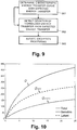
- Figure 10 illustrates for an example of the total energy transfer Q the part of the latent energy Q latent and the part of the sensible energy Q sensible dependent on the flow of thermal transfer fluid ⁇ W .
- step S211 the computer system 4 calculates the sensible Q sensible and the latent part Q latent of the total energy transfer Q.
- the computer system 4 uses the sensible heat ratio (SHR) for calculating the sensible Q sensible and the latent Q latent parts:
- Q latent Q total ⁇ Q sensible .
- step S21 2 the computer system 4 calculates for the sensible part Q sensible a normalized sensible part. Specifically, the computer system 4 calculates the normalized sensible part using the difference of the temperature T W in of the thermal transfer fluid entering the thermal energy exchanger 1 and the temperature T A in of the air entering the thermal energy exchanger 1: Q sensible T W i ⁇ T A i
- step S213 the computer system 4 calculates for the latent part Q latent a normalized latent part. Specifically, the computer system 4 calculates the normalized latent part, using the dew point temperature T dewpt of the air and inlet temperature of the thermal transfer fluid T W i : Q latent T dewpt ⁇ T W i .
- the normalized latent part is calculated, using the difference of the absolute humidity value W abs of the air entering the thermal energy exchanger 1 and an absolute humidity value at saturation W sat ( T W i ) at the temperature T W i of the thermal transfer fluid entering the thermal energy exchanger 1: Q latent W abs ⁇ W sat T W i
- Figure 12 illustrates in the upper graph an example of a plurality non-normalized data points S with data values of sensible energy transfer Q sensible per (non-normalized) flow of thermal transfer fluid ⁇ W .
- Figure 12 illustrates in the lower graph for said example of data points S the normalized data points Sn defined by the normalized sensible energy transfer Q sensible T W i ⁇ T A i per normalized flow of the thermal transfer fluid ⁇ W ⁇ A .
- Figure 13 illustrates in the upper graph an example of a plurality non-normalized data points L with data values of latent energy transfer Q latent per (non-normalized) flow of thermal transfer fluid ⁇ W .
- Figure 13 illustrates in the lower graph for said example of data points L the normalized data points Ln defined by the normalized latent energy transfer Q latent T dewpt ⁇ T W i or Q latent W abs ⁇ W sat T W i , respectively, per normalized flow of the thermal transfer fluid ⁇ W ⁇ A .
- graphs corresponding to those of Figures 11 , 12 , and 13 can be generated for scenarios where, without the use of flow sensors, the normalized total energy transfer is calculated entirely from enthalpy values and represented on the y-axis by normalized enthalpy values ⁇ H A LMED or ⁇ H W LMED , and the normalized flow of the thermal transfer fluid is represented on the x-axis by ⁇ H A ⁇ H W (the x-axis being the conventional independent axis).
- the computer system 4 determines a characteristic transfer curve for the thermal energy exchanger 1. Specifically, the computer system 4 determines the characteristic transfer curve for the thermal energy exchanger 1 using the normalized data points Pn, Sn, Ln calculated and recorded for the thermal energy exchanger 1 over an extended period of time, e.g. during a calibration or commissioning phase, of one or more days, or even several weeks or months, as a best fit for the plurality of normalized data points Pn, Sn, Ln. In the lower graph of Figure 11 the fitted characteristic transfer curve cP is indicated as a white curve running through the normalized data points Pn for normalized total energy transfer.
- the fitted characteristic transfer curve cS is indicated as a white curve running through the normalized data points Sn for normalized sensible energy transfer.
- the fitted characteristic transfer curve cL is indicated as a white curve running through the normalized data points Ln for normalized sensible energy transfer.
- the computer system 4 determines an efficiency boundary. Specifically, the computer system 4 determines the efficiency boundary bP, bS, bL (see Figures 11 , 12 , and 13 ) for the thermal energy exchanger 1 using the characteristic transfer curves cP, cS, cL or the normalized data points Pn, Sn, Ln. More specifically, the computer system 4 determines on the characteristic transfer curves cP, cS, cL boundary points BP, BS, BL (see Figures 11 , 12 , and 13 ) where the increase of the thermal energy transfer for an increase of the flow of thermal transfer fluid falls below a defined threshold value.
- the boundary bP, bS, bL is defined from the boundary points BP, BS, BL of several characteristic transfer curves cP, cS, cL determined for different sets of normalized data points, normalize separately for the total energy transfer, the latent energy transfer, and the sensible energy transfer, and/or for different values of the normalization variable(s) used, e.g.
- the log mean enthalpy difference the air flow ⁇ A , the flow of thermal transfer fluid ⁇ W , the temperature T W i of the thermal transfer fluid entering the thermal energy exchanger 1, the temperature T A i of the air entering the thermal energy exchanger 1, the dew point temperature T dewpt of the air, the absolute humidity value W abs of the air entering the thermal energy exchanger 1, and/or the absolute humidity value at saturation W sat ( T W i ) at the temperature T W i of the thermal transfer fluid entering the thermal energy exchanger 1.
- step S5 the controller 22 controls operation of the thermal energy exchanger 1 using the efficiency boundary bP, bS, bL and/or the characteristic energy transfer curve cP, cS, cL. Specifically, the controller 22 controls operation of the thermal energy exchanger 1 by controlling operating parameters of the thermal energy exchanger 1.
- the operating parameters of the thermal energy exchanger 1 include the flow of the thermal transfer fluid ⁇ W , the air flow ⁇ A , and/or the temperature T W in of the thermal transfer fluid entering the thermal energy exchanger 1.
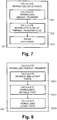
- the controller 22 controls the operating parameters such as to maintain a normalized performance of the thermal energy exchanger 1, whereby the controller 22 keeps the thermal energy exchanger 1 operating on the (applicable) characteristic energy transfer curve cP, cS, cL. Detection of deviations from the characteristic energy transfer curve cP, cS, cL will be described later with reference to Figure 9 .
- the controller 22 further controls the operating parameters such as to optimize performance of the thermal energy exchanger 1, whereby the controller 22 keeps the thermal energy exchanger 1 operating within an efficient area aP, aS, aL defined by the efficiency boundary bP, bS, bL.
- the thermal energy transfer increases comparably more with an increasing flow of thermal transfer fluid, than with an increasing flow of thermal transfer on the characteristic energy transfer curve outside the efficient area aP, aS, aL.
- efficiency boundaries and/or efficient areas can be determined correspondingly and apply accordingly to scenarios where, without the use of flow sensors, the normalized total energy transfer is calculated entirely from enthalpy values and represented by ⁇ H A LMED or ⁇ H W LMED , and the normalized flow of the thermal transfer fluid is represented by ⁇ H A ⁇ H W .
- the controller 22 is set to control the operating parameters to maintain normalized performance according to the first aspect and/or to optimize performance according to the second aspect.
- the efficiency boundary bP, bS, bL is transferred from the computer system 4 to the controller 22.
- the computer system 4 or the controller 22 respectively, generates control signals for controlling the operating parameters.
- the control signals are transmitted from the computer system 4 or the controller 22, respectively, to a building control system, a valve 21, a damper, a pump, a fan, and/or related actuators, for example.
- the computer system 4 determines the characteristic energy transfer curve cP, cS, cL that defines the expected energy transfer, i.e. the characteristic energy transfer curve cP, cS, cL that applies to the present operating conditions of the thermal energy exchanger 1, e.g. the current flow of air ⁇ A , the current flow of thermal transfer fluid ⁇ W , or the current inlet temperature of the thermal transfer fluid T W in .
- step S62 the computer system 4 detects a deviation of the normalized energy transfer from the expected energy transfer by comparing one or more data points with the current or recent normalized energy transfer to the expected energy transfer defined by the characteristic energy transfer curve cP, cS, cL selected in step S61.
- the computer system 4 Upon detection of a deviation, in step S63, the computer system 4 initiates exception processing. Depending on the scenario, embodiment, and/or configuration, the computer system 4 generates an alarm signal, an alarm message, selects an alternative characteristic energy transfer curve from a set of different characteristic energy transfer curves, and/or determines an alternative characteristic energy transfer curve using the plurality of measurement data sets. Specifically, for long term diagnostics, where for an ongoing period of time, e.g. several days, weeks, months, or even years, the normalized energy transfer continuously deviates from the expected energy transfer, the computer system 4 establishes that the current normalized data points or the related characteristic energy transfer curve deviate from the expected energy transfer, defined by an earlier characteristic energy transfer curve, e.g.
- the computer system 4 determines a new, alternative characteristic energy transfer curve. For short or long term optimizations of exceptions or deviations, for example, if the normalized data point is detected to be within the efficient area aP, aS, aL, but below the characteristic energy transfer curve cP, cS, cL, the controller 22 controls the operating parameters such as to move the normalized data point onto the characteristic energy transfer curve cP, cS, cL. Thus, the controller 22 corrects and optimizes situations that arise from temporary disturbances or sub-optimal conditions or settings.
- the controller 22 if the normalized data point is detected to be within the efficient area aP, aS, aL, but above the characteristic energy transfer curve cP, cS, cL, the controller 22 generates an alarm or diagnostic report that indicates the detection of deviations that are caused, for example, because of sub-optimal or incorrect system setup configuration, such as arrangements of distant temperature sensors that cause excessive time lags or other settings that lead to instable system behaviours.
- the normalized total energy transfer is calculated using the temperatures T W i , T W o of the thermal transfer fluid entering or exiting the thermal energy exchanger 1, respectively, and the temperatures T A i , T Ao of the air entering or exiting the thermal energy exchanger 1, respectively, for example: Q ⁇ T W i ⁇ T W o T a i or Q ⁇ T W i ⁇ T W o T a o ⁇ T a i .
Landscapes
- Engineering & Computer Science (AREA)
- Mechanical Engineering (AREA)
- General Engineering & Computer Science (AREA)
- Chemical & Material Sciences (AREA)
- Combustion & Propulsion (AREA)
- Signal Processing (AREA)
- Physics & Mathematics (AREA)
- Fuzzy Systems (AREA)
- Mathematical Physics (AREA)
- Human Computer Interaction (AREA)
- Fluid Mechanics (AREA)
- General Physics & Mathematics (AREA)
- Automation & Control Theory (AREA)
- Air Conditioning Control Device (AREA)
Claims (25)
- Procédé d'exploitation d'un échangeur (1) d'énergie thermique servant à échanger de l'énergie thermique entre un fluide de transfert thermique, s'écoulant à travers l'échangeur (1) d'énergie thermique dans un conduit (200) de fluide, et de l'air, qui est canalisé à travers l'échangeur (1) d'énergie thermique dans une gaine (300) d'air, le procédé comportant les étapes consistant à :
enregistrer dans un système (40) de commande une pluralité d'ensembles de données de mesure, chacun des ensembles de données de mesure comprenant, pour un instant différent, des valeurs de données définissant un transfert d'énergie normalisé qui représente l'énergie thermique transférée dans l'échangeur (1) d'énergie thermique, du fluide de transfert thermique à l'air, normalisée par une ou plusieurs variables de normalisation comprenant au moins une variable côté air ; caractérisé en ce qu'il comporte en outre :le calcul par le système (40) de commande, pour chacun des ensembles de données de mesure, d'un point de données normalisées (Pn, Sn, Ln) défini par le transfert d'énergie normalisé ; etla détermination par le système (40) de commande, pour l'échangeur (1) d'énergie thermique, d'une courbe caractéristique de transfert d'énergie (cP, cS, cL) qui s'ajuste aux points de données normalisées (Pn, Sn, Ln) ; etla commande, par le système (40) de commande, de paramètres de fonctionnement, les paramètres de fonctionnement incluant le débit de fluide de transfert thermique à travers l'échangeur d'énergie thermique, le débit d'air à travers l'échangeur d'énergie thermique, et/ou la température du fluide de transfert thermique entrant dans l'échangeur d'énergie thermique. - Procédé selon la revendication 1, comportant en outre la détermination, par le système (40) de commande, d'une frontière (bP, bS, bL) pour le transfert efficient d'énergie thermique dans l'échangeur (1) d'énergie thermique entre le fluide de transfert thermique et l'air, la frontière (bP, bS, bL) définissant une zone efficiente (aP, aS, aL) où, sur la courbe caractéristique de transfert d'énergie (cP, cS, cL), le transfert d'énergie thermique présente un meilleur rendement énergétique que sur la courbe caractéristique de transfert d'énergie (cP, cS, cL) en dehors de la zone efficiente (aP, aS, aL) ; et le maintien, par le système (40) de commande, du fonctionnement de l'échangeur (1) d'énergie thermique à l'intérieur de ladite zone efficiente (aP, aS, aL).
- Procédé selon l'une des revendications 1 et 2, le système (40) de commande commandant des paramètres de fonctionnement pour maintenir le fonctionnement de l'échangeur (1) d'énergie thermique sur la courbe caractéristique de transfert d'énergie (cP, cS, cL), les paramètres de fonctionnement comportant au moins un paramètre parmi : le débit de fluide de transfert thermique à travers l'échangeur (1) d'énergie thermique, le débit d'air à travers l'échangeur (1) d'énergie thermique, et la température du fluide de transfert thermique entrant dans l'échangeur (1) d'énergie thermique.
- Procédé selon l'une des revendications 1 à 3, chacun des ensembles de données de mesure comprenant une valeur d'enthalpie d'entrée d'air, une valeur d'enthalpie de sortie d'air, une valeur d'enthalpie d'entrée de fluide de transfert thermique, et une valeur d'enthalpie de sortie de fluide de transfert thermique ; et le système (40) de commande calculant le transfert d'énergie normalisé pour chacun des points de données normalisées (Pn, Sn, Ln), en utilisant la valeur d'enthalpie d'entrée d'air, la valeur d'enthalpie de sortie d'air, la valeur d'enthalpie d'entrée de fluide de transfert thermique, et la valeur d'enthalpie de sortie de fluide de transfert thermique.
- Procédé selon l'une des revendications 1 à 3, chacun des ensembles de données de mesure comprenant une valeur de température de l'air entrant dans l'échangeur (1) d'énergie thermique, une valeur de température de l'air sortant de l'échangeur (1) d'énergie thermique, une valeur d'humidité de l'air entrant dans l'échangeur (1) d'énergie thermique, une valeur d'humidité de l'air sortant de l'échangeur (1) d'énergie thermique, une valeur de température du fluide de transfert thermique entrant dans l'échangeur (1) d'énergie thermique, et une valeur de température du fluide de transfert thermique sortant de l'échangeur (1) d'énergie thermique ; et le système (40) de commande calculant le transfert d'énergie normalisé pour chacun des points de données normalisées (Pn, Sn, Ln), en utilisant la valeur de température de l'air entrant dans l'échangeur (1) d'énergie thermique, la valeur de température de l'air sortant de l'échangeur (1) d'énergie thermique, la valeur d'humidité de l'air entrant dans l'échangeur (1) d'énergie thermique, la valeur d'humidité de l'air sortant de l'échangeur (1) d'énergie thermique, la valeur de température du fluide de transfert thermique entrant dans l'échangeur (1) d'énergie thermique, et la valeur de température du fluide de transfert thermique sortant de l'échangeur (1) d'énergie thermique.
- Procédé selon l'une des revendications 1 à 5, chacun des ensembles de données de mesure comprenant, pour les différents instants, le débit de fluide de transfert thermique à travers l'échangeur (1) d'énergie thermique et le débit d'air à travers l'échangeur (1) d'énergie thermique ; et le système (40) de commande calculant, pour chacun des points de données normalisées (Pn, Sn, Ln), un débit normalisé de fluide de transfert thermique à travers le conduit (200) de fluide normalisé par le débit d'air.
- Procédé selon l'une des revendications 1 à 6, chacun des ensembles de données de mesure comprenant des valeurs de données définissant une différence d'enthalpie moyenne logarithmique issue d'une différence d'enthalpie d'entrée de l'air entrant dans l'échangeur (1) d'énergie thermique et du fluide de transfert thermique entrant dans l'échangeur (1) d'énergie thermique, et d'une différence d'enthalpie de sortie de l'air sortant de l'échangeur (1) d'énergie thermique et du fluide de transfert thermique sortant de l'échangeur (1) d'énergie thermique ; et le système (40) de commande calculant le transfert d'énergie normalisé pour chacun des points de données normalisées (Pn) en utilisant la différence d'enthalpie moyenne logarithmique.
- Procédé selon l'une des revendications 1 à 7, chacun des ensembles de données de mesure comprenant le débit d'air à travers l'échangeur (1) d'énergie thermique ; et le système (40) de commande calculant le transfert d'énergie normalisé pour chacun des points de données normalisées (Pn) en utilisant le débit d'air à travers l'échangeur (1) d'énergie thermique.
- Procédé selon l'une des revendications 1 à 7, chacun des ensembles de données de mesure comprenant le débit de fluide de transfert thermique à travers l'échangeur (1) d'énergie thermique ; et le système (40) de commande calculant le transfert d'énergie normalisé pour chacun des points de données normalisées (Pn) en utilisant le débit de fluide de transfert thermique à travers l'échangeur (1) d'énergie thermique.
- Procédé selon l'une des revendications 1 à 5, chacun des ensembles de données de mesure comprenant, pour les différents instants, des valeurs de données définissant une différence d'enthalpie côté air de l'air entrant dans l'échangeur (1) d'énergie thermique et de l'air sortant de l'échangeur (1) d'énergie thermique, et des valeurs de données définissant une différence d'enthalpie côté fluide de transfert thermique du fluide de transfert thermique entrant dans l'échangeur (1) d'énergie thermique et du fluide de transfert thermique sortant de l'échangeur (1) d'énergie thermique ; et le système (40) de commande calculant, pour chacun des points de données normalisées (Pn) une valeur représentative du débit normalisé, à partir de la différence d'enthalpie côté air et de la différence d'enthalpie côté fluide de transfert thermique.
- Procédé selon la revendication 10, chacun des ensembles de données de mesure comprenant des valeurs de données définissant une différence d'enthalpie moyenne logarithmique issue d'une différence d'enthalpie d'entrée de l'air entrant dans l'échangeur (1) d'énergie thermique et du fluide de transfert thermique entrant dans l'échangeur (1) d'énergie thermique, et d'une différence d'enthalpie de sortie de l'air sortant de l'échangeur (1) d'énergie thermique et du fluide de transfert thermique sortant de l'échangeur (1) d'énergie thermique ; et le système (40) de commande calculant le transfert d'énergie normalisé pour chacun des points de données normalisées (Pn) en utilisant la différence d'enthalpie côté air et la différence d'enthalpie moyenne logarithmique.
- Procédé selon la revendication 10, chacun des ensembles de données de mesure comprenant des valeurs de données définissant une différence d'enthalpie moyenne logarithmique issue d'une différence d'enthalpie d'entrée de l'air entrant dans l'échangeur (1) d'énergie thermique et du fluide de transfert thermique entrant dans l'échangeur (1) d'énergie thermique, et d'une différence d'enthalpie de sortie de l'air sortant de l'échangeur d'énergie thermique et du fluide de transfert thermique sortant de l'échangeur d'énergie thermique ; et le système (40) de commande calculant le transfert d'énergie normalisé pour chacun des points de données normalisées (Pn) en utilisant la différence d'enthalpie côté fluide de transfert thermique et la différence d'enthalpie moyenne logarithmique.
- Procédé selon l'une des revendications 2 à 5, chacun des ensembles de données de mesure comprenant des valeurs de données servant à déterminer une partie sensible et une partie latente de l'énergie thermique transférée dans l'échangeur (1) d'énergie thermique, du fluide de transfert thermique à l'air ; le système (40) de commande calculant une partie sensible normalisée et une partie latente normalisée, en utilisant une ou plusieurs variables de normalisation ; et le système (40) de commande déterminant des frontières (bS, bL) pour le transfert efficient d'énergie thermique dans l'échangeur (1) d'énergie thermique entre le fluide de transfert thermique et l'air séparément pour la partie sensible normalisée et la partie latente normalisée ; et le système (40) de commande maintenant le fonctionnement de l'échangeur d'énergie thermique à l'intérieur de zones efficientes (aS, aL) définies par lesdites frontières (bS, bL).
- Procédé selon la revendication 13, chacun des ensembles de données de mesure comprenant une valeur de température du fluide de transfert thermique entrant dans l'échangeur (1) d'énergie thermique, et une valeur de température de l'air entrant dans l'échangeur (1) d'énergie thermique ; et le système (40) de commande calculant la partie sensible normalisée (Sn) de l'énergie thermique transférée dans l'échangeur (1) d'énergie thermique en utilisant la différence de la valeur de température du fluide de transfert thermique entrant dans l'échangeur (1) d'énergie thermique et de la valeur de température de l'air entrant dans l'échangeur (1) d'énergie thermique.
- Procédé selon l'une des revendications 13 et 14, chacun des ensembles de données de mesure comprenant une valeur de température du fluide de transfert thermique entrant dans l'échangeur (1) d'énergie thermique ; et le système (40) de commande calculant la partie latente normalisée (Ln) de l'énergie thermique transférée dans l'échangeur (1) d'énergie thermique en utilisant la différence de la valeur de température d'une température de point de rosée de l'air et de la température du fluide de transfert thermique entrant dans l'échangeur (1) d'énergie thermique.
- Procédé selon l'une des revendications 13 et 14, chacun des ensembles de données de mesure comprenant une valeur de température du fluide de transfert thermique entrant dans l'échangeur (1) d'énergie thermique, une valeur absolue d'humidité de l'air entrant dans l'échangeur (1) d'énergie thermique, et une valeur de température du fluide de transfert thermique entrant dans l'échangeur (1) d'énergie thermique ; et le système (40) de commande calculant la partie latente normalisée (Ln) de l'énergie thermique transférée dans l'échangeur (1) d'énergie thermique en utilisant la différence de la valeur absolue d'humidité de l'air entrant dans l'échangeur (1) d'énergie thermique et d'une valeur absolue d'humidité à saturation à la valeur de température du fluide de transfert thermique entrant dans l'échangeur (1) d'énergie thermique.
- Procédé selon l'une des revendications 1 à 16, comportant en outre la détermination, par le système (40) de commande, d'une courbe caractéristique de transfert d'énergie (cP, cS, cL), qui indique un transfert d'énergie prévu dans l'échangeur (1) d'énergie thermique du fluide de transfert thermique à l'air ; la détection, par le système (40) de commande, d'un écart du transfert d'énergie normalisé (Pn, Sn, Ln) par rapport au transfert d'énergie prévu ; et, suite à la détection d'un écart, le lancement, par le système (40) de commande, d'un traitement d'exception.
- Procédé selon la revendication 17, comportant en outre la sélection, par le système (40) de commande, d'une courbe caractéristique de transfert d'énergie (cP, cS, cL) à partir d'un ensemble de différentes courbes caractéristiques de transfert d'énergie (cP, cS, cL), qui indiquent, pour différents paramètres côté air, un transfert d'énergie prévu dans l'échangeur (1) d'énergie thermique du fluide de transfert thermique à l'air, en utilisant des paramètres côté air compris dans les ensembles de données de mesure.
- Procédé selon l'une des revendications 17 et 18, comportant en outre l'inclusion dans le traitement d'exception, par le système (40) de commande, d'au moins une des étapes suivantes : génération d'un signal d'alarme, sélection d'une courbe caractéristique de transfert d'énergie (cP, cS, cL) de substitution à partir d'un ensemble de courbes caractéristiques de transfert d'énergie (cP, cS, cL) différentes, et détermination d'une courbe caractéristique de transfert d'énergie (cP, cS, cL) de substitution en utilisant la pluralité d'ensembles de données de mesure.
- Système (40) de commande destiné à faire fonctionner un échangeur (1) d'énergie thermique servant à échanger de l'énergie thermique entre un fluide de transfert thermique, s'écoulant à travers l'échangeur (1) d'énergie thermique dans un conduit (200) de fluide, et de l'air, qui est canalisé à travers l'échangeur (1) d'énergie thermique dans une gaine (300) d'air, le système (40) de commande comportant au moins un processeur configuré pour :enregistrer dans le système (40) de commande une pluralité d'ensembles de données de mesure, chacun des ensembles de données de mesure comprenant, pour un instant différent, des valeurs de données définissant un transfert d'énergie normalisé qui représente l'énergie thermique transférée dans l'échangeur (1) d'énergie thermique, du fluide de transfert thermique à l'air, normalisée par une ou plusieurs variables de normalisation comprenant au moins une variable côté air ;calculer, pour chacun des ensembles de données de mesure, un point de données normalisées (Pn, Sn, Ln) défini par le transfert d'énergie normalisé ; etdéterminer, pour l'échangeur (1) d'énergie thermique, une courbe caractéristique de transfert d'énergie (cP, cS, cL) qui s'ajuste aux points de données normalisées (Pn, Sn, Ln).
- Système (40) de commande selon la revendication 20, le processeur étant en outre configuré pour déterminer une frontière (bP, bS, bL) pour le transfert efficient d'énergie thermique dans l'échangeur (1) d'énergie thermique entre le fluide de transfert thermique et l'air, la frontière (bP, bS, bL) définissant une zone efficiente (aP, aS, aL) où, sur la courbe caractéristique de transfert d'énergie (cP, cS, cL), le transfert d'énergie thermique présente un meilleur rendement énergétique que sur la courbe caractéristique de transfert d'énergie (cP, cS, cL) en dehors de la zone efficiente (aP, aS, aL) ; et maintenir le fonctionnement de l'échangeur (1) d'énergie thermique à l'intérieur de ladite zone efficiente (aP, aS, aL).
- Système (40) de commande selon l'une des revendications 20 et 21, le processeur étant en outre configuré pour réaliser des étapes du procédé selon l'une des revendications 2 à 19.
- Produit de programme d'ordinateur comportant un support non transitoire lisible par ordinateur sur lequel est stocké un code de programme d'ordinateur configuré pour commander un processeur d'un système (40) de commande destiné à faire fonctionner un échangeur (1) d'énergie thermique servant à échanger de l'énergie thermique entre un fluide de transfert thermique, s'écoulant à travers l'échangeur (1) d'énergie thermique dans un conduit (200) de fluide, et de l'air, qui est canalisé à travers l'échangeur (1) d'énergie thermique dans une gaine (300) d'air, de telle façon que le processeur réalise les étapes suivantes :Enregistrement, dans le système (40) de commande, d'une pluralité d'ensembles de données de mesure, chacun des ensembles de données de mesure comprenant, pour un instant différent, des valeurs de données définissant un transfert d'énergie normalisé qui représente l'énergie thermique transférée dans l'échangeur (1) d'énergie thermique, du fluide de transfert thermique à l'air, normalisée par une ou plusieurs variables de normalisation comprenant au moins une variable côté air ;calcul, pour chacun des ensembles de données de mesure, d'un point de données normalisées (Pn, Sn, Ln) défini par le transfert d'énergie normalisé ; etdétermination, pour l'échangeur (1) d'énergie thermique, d'une courbe caractéristique de transfert d'énergie (cP, cS, cL) qui s'ajuste aux points de données normalisées (Pn, Sn, Ln).
- Produit de programme d'ordinateur selon la revendication 23, le code de programme d'ordinateur étant en outre configuré pour commander le processeur de telle façon que le processeur détermine une frontière (bP, bS, bL) pour le transfert efficient d'énergie thermique dans l'échangeur (1) d'énergie thermique entre le fluide de transfert thermique et l'air, la frontière (bP, bS, bL) définissant une zone efficiente (aP, aS, aL) où, sur la courbe caractéristique de transfert d'énergie (cP, cS, cL), le transfert d'énergie thermique présente un meilleur rendement énergétique que sur la courbe caractéristique de transfert d'énergie (cP, cS, cL) en dehors de la zone efficiente (aP, aS, aL) ; et maintienne le fonctionnement de l'échangeur (1) d'énergie thermique à l'intérieur de ladite zone efficiente (aP, aS, aL).
- Produit de programme d'ordinateur selon l'une des revendications 23 et 24, le code de programme d'ordinateur étant en outre configuré pour commander le processeur de telle façon que le processeur réalise des étapes du procédé selon l'une des revendications 2 à 19.
Applications Claiming Priority (2)
| Application Number | Priority Date | Filing Date | Title |
|---|---|---|---|
| CH12552015 | 2015-09-01 | ||
| PCT/EP2016/067657 WO2017036674A1 (fr) | 2015-09-01 | 2016-07-25 | Procédé et système de fonctionnement d'échangeur d'énergie thermique |
Publications (2)
| Publication Number | Publication Date |
|---|---|
| EP3344925A1 EP3344925A1 (fr) | 2018-07-11 |
| EP3344925B1 true EP3344925B1 (fr) | 2021-05-26 |
Family
ID=54065139
Family Applications (1)
| Application Number | Title | Priority Date | Filing Date |
|---|---|---|---|
| EP16751208.6A Active EP3344925B1 (fr) | 2015-09-01 | 2016-07-25 | Procédé et système de fonctionnement d'échangeur d'énergie thermique |
Country Status (4)
| Country | Link |
|---|---|
| US (1) | US10627129B2 (fr) |
| EP (1) | EP3344925B1 (fr) |
| CN (1) | CN108291734B (fr) |
| WO (1) | WO2017036674A1 (fr) |
Cited By (1)
| Publication number | Priority date | Publication date | Assignee | Title |
|---|---|---|---|---|
| EP4411266A1 (fr) | 2023-02-01 | 2024-08-07 | Siemens Schweiz AG | Limitation de température de retour pondérée |
Families Citing this family (6)
| Publication number | Priority date | Publication date | Assignee | Title |
|---|---|---|---|---|
| US10544955B2 (en) | 2017-03-09 | 2020-01-28 | Johnson Controls Technology Company | Dynamically updatable building management system control platform |
| EP3489591B1 (fr) | 2017-11-24 | 2021-09-01 | Siemens Schweiz AG | Échangeur d'énergie thermique intelligent |
| WO2019238631A1 (fr) | 2018-06-12 | 2019-12-19 | Belimo Holding Ag | Procédé et système de régulation de transfert d'énergie d'échangeur d'énergie thermique |
| US20230071155A1 (en) * | 2020-01-24 | 2023-03-09 | Belimo Holding Ag | Method and system for monitoring energy flow of hvac system |
| WO2022029127A1 (fr) * | 2020-08-04 | 2022-02-10 | Belimo Holding Ag | Dispositif et procédé pour commander un orifice d'une vanne dans un système de chauffage, de ventilation et de climatisation (cvc) |
| CN115133076B (zh) * | 2022-07-12 | 2025-01-24 | 同济大学 | 一种燃料电池空气路在线自适应防喘振控制方法 |
Family Cites Families (12)
| Publication number | Priority date | Publication date | Assignee | Title |
|---|---|---|---|---|
| ES2561829T3 (es) * | 2002-10-15 | 2016-03-01 | Danfoss A/S | Un procedimiento para detectar una anomalía de un intercambiador de calor |
| JP2006010322A (ja) * | 2004-06-22 | 2006-01-12 | Yokogawa Electric Corp | 熱式流量計 |
| US9631831B2 (en) * | 2010-11-17 | 2017-04-25 | Bilimo Holding Ag | Method for controlling the opening of an HVAC valve based on the energy-per-flow gradient |
| CN102135021B (zh) * | 2011-02-25 | 2013-12-25 | 华东理工大学 | 一种工业抽汽冷凝式蒸汽轮机的轴功率预测方法 |
| RU113837U1 (ru) * | 2011-07-13 | 2012-02-27 | Сергей Сергеевич Сергеев | Устройство для определения эффективности теплоснабжения здания |
| CH705466A1 (de) * | 2011-09-05 | 2013-03-15 | Belimo Holding Ag | Verfahren zum Betreiben und/oder Überwachen einer HVAC-Anlage sowie HVAC-Anlage zur Durchführung des Verfahrens. |
| CN102705957B (zh) * | 2012-06-07 | 2014-06-11 | 华南理工大学 | 办公建筑中央空调逐时冷负荷在线预测方法及系统 |
| US8496234B1 (en) * | 2012-07-16 | 2013-07-30 | Massachusetts Institute Of Technology | Thermodynamic balancing of combined heat and mass exchange devices |
| US9874880B2 (en) * | 2013-05-16 | 2018-01-23 | Belimo Holding Ag | Device and method for controlling opening of a valve in an HVAC system |
| US20150060557A1 (en) * | 2013-08-30 | 2015-03-05 | LH Thermostat Systems LLC | Energy saving apparatus, system and method |
| FR3011624B1 (fr) * | 2013-10-09 | 2017-12-22 | Commissariat Energie Atomique | Systeme et procede de traitement et de conditionnement d'air |
| EP3770518A3 (fr) * | 2013-12-20 | 2021-06-23 | Belimo Holding AG | Commande de soupape dans un système cvc avec des capteurs |
-
2016
- 2016-07-25 WO PCT/EP2016/067657 patent/WO2017036674A1/fr not_active Ceased
- 2016-07-25 US US15/744,178 patent/US10627129B2/en active Active
- 2016-07-25 EP EP16751208.6A patent/EP3344925B1/fr active Active
- 2016-07-25 CN CN201680050352.5A patent/CN108291734B/zh not_active Expired - Fee Related
Non-Patent Citations (1)
| Title |
|---|
| None * |
Cited By (1)
| Publication number | Priority date | Publication date | Assignee | Title |
|---|---|---|---|---|
| EP4411266A1 (fr) | 2023-02-01 | 2024-08-07 | Siemens Schweiz AG | Limitation de température de retour pondérée |
Also Published As
| Publication number | Publication date |
|---|---|
| CN108291734A (zh) | 2018-07-17 |
| WO2017036674A1 (fr) | 2017-03-09 |
| US20180195753A1 (en) | 2018-07-12 |
| CN108291734B (zh) | 2020-08-18 |
| EP3344925A1 (fr) | 2018-07-11 |
| US10627129B2 (en) | 2020-04-21 |
Similar Documents
| Publication | Publication Date | Title |
|---|---|---|
| EP3344925B1 (fr) | Procédé et système de fonctionnement d'échangeur d'énergie thermique | |
| EP2997430B1 (fr) | Dispositif et procédé permettant de commander l'ouverture d'une vanne dans un système de chauffage/climatisation | |
| US9835347B2 (en) | State-based control in an air handling unit | |
| JP5629189B2 (ja) | 制御装置および方法 | |
| CN111213013B (zh) | 用于控制hvac系统中的阀的方法和系统 | |
| CN108644968B (zh) | 用于空调系统的控制方法 | |
| EP3306216B1 (fr) | Dispositif de régulation pour système à pompe à chaleur, et système à pompe à chaleur muni dudit dispositif | |
| WO2016035121A1 (fr) | Dispositif de commande de système climatisation et procédé de commande de système de climatisation | |
| US10739031B2 (en) | System and method using mobile device for automatic control on heating, ventilation and air conditioning | |
| EP3475623B1 (fr) | Procédé et dispositifs de réglage de réseau de transport de fluide | |
| US20210025608A1 (en) | Hvac system with on-off control | |
| CN108826599B (zh) | 用于空调系统的控制方法 | |
| CN108592353B (zh) | 用于空调系统的控制方法 | |
| US11609019B2 (en) | Device and method for controlling an orifice of a valve in an HVAC system | |
| EP3098529B1 (fr) | Commande coordonnée d'un système cvc utilisant une demande système agrégée | |
| US12072116B2 (en) | Method and system for controlling energy transfer of a thermal energy exchanger | |
| JP7051671B2 (ja) | 空調制御装置及びプログラム | |
| WO2017105952A1 (fr) | Commande adaptative de système de cvca | |
| US20260016184A1 (en) | System and method for controlling an hvac unit | |
| CN116659048B (zh) | 地暖空调器控制方法、装置、设备及存储介质 | |
| US12618584B2 (en) | Gain-scheduling system and method for improving fan speed control in air handling units | |
| CN108332366A (zh) | 空气调节机控制装置及空气调节机控制方法 | |
| CN121175525A (zh) | 用于加热通风和冷却系统的控制系统 |
Legal Events
| Date | Code | Title | Description |
|---|---|---|---|
| STAA | Information on the status of an ep patent application or granted ep patent |
Free format text: STATUS: THE INTERNATIONAL PUBLICATION HAS BEEN MADE |
|
| PUAI | Public reference made under article 153(3) epc to a published international application that has entered the european phase |
Free format text: ORIGINAL CODE: 0009012 |
|
| STAA | Information on the status of an ep patent application or granted ep patent |
Free format text: STATUS: REQUEST FOR EXAMINATION WAS MADE |
|
| 17P | Request for examination filed |
Effective date: 20180313 |
|
| AK | Designated contracting states |
Kind code of ref document: A1 Designated state(s): AL AT BE BG CH CY CZ DE DK EE ES FI FR GB GR HR HU IE IS IT LI LT LU LV MC MK MT NL NO PL PT RO RS SE SI SK SM TR |
|
| AX | Request for extension of the european patent |
Extension state: BA ME |
|
| DAV | Request for validation of the european patent (deleted) | ||
| DAX | Request for extension of the european patent (deleted) | ||
| GRAP | Despatch of communication of intention to grant a patent |
Free format text: ORIGINAL CODE: EPIDOSNIGR1 |
|
| STAA | Information on the status of an ep patent application or granted ep patent |
Free format text: STATUS: GRANT OF PATENT IS INTENDED |
|
| INTG | Intention to grant announced |
Effective date: 20201217 |
|
| GRAS | Grant fee paid |
Free format text: ORIGINAL CODE: EPIDOSNIGR3 |
|
| GRAA | (expected) grant |
Free format text: ORIGINAL CODE: 0009210 |
|
| STAA | Information on the status of an ep patent application or granted ep patent |
Free format text: STATUS: THE PATENT HAS BEEN GRANTED |
|
| AK | Designated contracting states |
Kind code of ref document: B1 Designated state(s): AL AT BE BG CH CY CZ DE DK EE ES FI FR GB GR HR HU IE IS IT LI LT LU LV MC MK MT NL NO PL PT RO RS SE SI SK SM TR |
|
| REG | Reference to a national code |
Ref country code: GB Ref legal event code: FG4D |
|
| REG | Reference to a national code |
Ref country code: CH Ref legal event code: EP |
|
| REG | Reference to a national code |
Ref country code: DE Ref legal event code: R096 Ref document number: 602016058412 Country of ref document: DE |
|
| REG | Reference to a national code |
Ref country code: AT Ref legal event code: REF Ref document number: 1396613 Country of ref document: AT Kind code of ref document: T Effective date: 20210615 |
|
| REG | Reference to a national code |
Ref country code: IE Ref legal event code: FG4D |
|
| REG | Reference to a national code |
Ref country code: LT Ref legal event code: MG9D |
|
| REG | Reference to a national code |
Ref country code: AT Ref legal event code: MK05 Ref document number: 1396613 Country of ref document: AT Kind code of ref document: T Effective date: 20210526 |
|
| PG25 | Lapsed in a contracting state [announced via postgrant information from national office to epo] |
Ref country code: LT Free format text: LAPSE BECAUSE OF FAILURE TO SUBMIT A TRANSLATION OF THE DESCRIPTION OR TO PAY THE FEE WITHIN THE PRESCRIBED TIME-LIMIT Effective date: 20210526 Ref country code: FI Free format text: LAPSE BECAUSE OF FAILURE TO SUBMIT A TRANSLATION OF THE DESCRIPTION OR TO PAY THE FEE WITHIN THE PRESCRIBED TIME-LIMIT Effective date: 20210526 Ref country code: HR Free format text: LAPSE BECAUSE OF FAILURE TO SUBMIT A TRANSLATION OF THE DESCRIPTION OR TO PAY THE FEE WITHIN THE PRESCRIBED TIME-LIMIT Effective date: 20210526 Ref country code: AT Free format text: LAPSE BECAUSE OF FAILURE TO SUBMIT A TRANSLATION OF THE DESCRIPTION OR TO PAY THE FEE WITHIN THE PRESCRIBED TIME-LIMIT Effective date: 20210526 Ref country code: BG Free format text: LAPSE BECAUSE OF FAILURE TO SUBMIT A TRANSLATION OF THE DESCRIPTION OR TO PAY THE FEE WITHIN THE PRESCRIBED TIME-LIMIT Effective date: 20210826 |
|
| REG | Reference to a national code |
Ref country code: NL Ref legal event code: MP Effective date: 20210526 |
|
| PG25 | Lapsed in a contracting state [announced via postgrant information from national office to epo] |
Ref country code: GR Free format text: LAPSE BECAUSE OF FAILURE TO SUBMIT A TRANSLATION OF THE DESCRIPTION OR TO PAY THE FEE WITHIN THE PRESCRIBED TIME-LIMIT Effective date: 20210827 Ref country code: LV Free format text: LAPSE BECAUSE OF FAILURE TO SUBMIT A TRANSLATION OF THE DESCRIPTION OR TO PAY THE FEE WITHIN THE PRESCRIBED TIME-LIMIT Effective date: 20210526 Ref country code: IS Free format text: LAPSE BECAUSE OF FAILURE TO SUBMIT A TRANSLATION OF THE DESCRIPTION OR TO PAY THE FEE WITHIN THE PRESCRIBED TIME-LIMIT Effective date: 20210926 Ref country code: PT Free format text: LAPSE BECAUSE OF FAILURE TO SUBMIT A TRANSLATION OF THE DESCRIPTION OR TO PAY THE FEE WITHIN THE PRESCRIBED TIME-LIMIT Effective date: 20210927 Ref country code: NO Free format text: LAPSE BECAUSE OF FAILURE TO SUBMIT A TRANSLATION OF THE DESCRIPTION OR TO PAY THE FEE WITHIN THE PRESCRIBED TIME-LIMIT Effective date: 20210826 Ref country code: PL Free format text: LAPSE BECAUSE OF FAILURE TO SUBMIT A TRANSLATION OF THE DESCRIPTION OR TO PAY THE FEE WITHIN THE PRESCRIBED TIME-LIMIT Effective date: 20210526 Ref country code: RS Free format text: LAPSE BECAUSE OF FAILURE TO SUBMIT A TRANSLATION OF THE DESCRIPTION OR TO PAY THE FEE WITHIN THE PRESCRIBED TIME-LIMIT Effective date: 20210526 Ref country code: SE Free format text: LAPSE BECAUSE OF FAILURE TO SUBMIT A TRANSLATION OF THE DESCRIPTION OR TO PAY THE FEE WITHIN THE PRESCRIBED TIME-LIMIT Effective date: 20210526 |
|
| PG25 | Lapsed in a contracting state [announced via postgrant information from national office to epo] |
Ref country code: NL Free format text: LAPSE BECAUSE OF FAILURE TO SUBMIT A TRANSLATION OF THE DESCRIPTION OR TO PAY THE FEE WITHIN THE PRESCRIBED TIME-LIMIT Effective date: 20210526 |
|
| PG25 | Lapsed in a contracting state [announced via postgrant information from national office to epo] |
Ref country code: SM Free format text: LAPSE BECAUSE OF FAILURE TO SUBMIT A TRANSLATION OF THE DESCRIPTION OR TO PAY THE FEE WITHIN THE PRESCRIBED TIME-LIMIT Effective date: 20210526 Ref country code: SK Free format text: LAPSE BECAUSE OF FAILURE TO SUBMIT A TRANSLATION OF THE DESCRIPTION OR TO PAY THE FEE WITHIN THE PRESCRIBED TIME-LIMIT Effective date: 20210526 Ref country code: CZ Free format text: LAPSE BECAUSE OF FAILURE TO SUBMIT A TRANSLATION OF THE DESCRIPTION OR TO PAY THE FEE WITHIN THE PRESCRIBED TIME-LIMIT Effective date: 20210526 Ref country code: EE Free format text: LAPSE BECAUSE OF FAILURE TO SUBMIT A TRANSLATION OF THE DESCRIPTION OR TO PAY THE FEE WITHIN THE PRESCRIBED TIME-LIMIT Effective date: 20210526 Ref country code: DK Free format text: LAPSE BECAUSE OF FAILURE TO SUBMIT A TRANSLATION OF THE DESCRIPTION OR TO PAY THE FEE WITHIN THE PRESCRIBED TIME-LIMIT Effective date: 20210526 Ref country code: RO Free format text: LAPSE BECAUSE OF FAILURE TO SUBMIT A TRANSLATION OF THE DESCRIPTION OR TO PAY THE FEE WITHIN THE PRESCRIBED TIME-LIMIT Effective date: 20210526 Ref country code: ES Free format text: LAPSE BECAUSE OF FAILURE TO SUBMIT A TRANSLATION OF THE DESCRIPTION OR TO PAY THE FEE WITHIN THE PRESCRIBED TIME-LIMIT Effective date: 20210526 |
|
| REG | Reference to a national code |
Ref country code: DE Ref legal event code: R097 Ref document number: 602016058412 Country of ref document: DE |
|
| PLBE | No opposition filed within time limit |
Free format text: ORIGINAL CODE: 0009261 |
|
| STAA | Information on the status of an ep patent application or granted ep patent |
Free format text: STATUS: NO OPPOSITION FILED WITHIN TIME LIMIT |
|
| PG25 | Lapsed in a contracting state [announced via postgrant information from national office to epo] |
Ref country code: MC Free format text: LAPSE BECAUSE OF FAILURE TO SUBMIT A TRANSLATION OF THE DESCRIPTION OR TO PAY THE FEE WITHIN THE PRESCRIBED TIME-LIMIT Effective date: 20210526 |
|
| REG | Reference to a national code |
Ref country code: BE Ref legal event code: MM Effective date: 20210731 |
|
| GBPC | Gb: european patent ceased through non-payment of renewal fee |
Effective date: 20210826 |
|
| 26N | No opposition filed |
Effective date: 20220301 |
|
| PG25 | Lapsed in a contracting state [announced via postgrant information from national office to epo] |
Ref country code: IS Free format text: LAPSE BECAUSE OF FAILURE TO SUBMIT A TRANSLATION OF THE DESCRIPTION OR TO PAY THE FEE WITHIN THE PRESCRIBED TIME-LIMIT Effective date: 20210926 Ref country code: LU Free format text: LAPSE BECAUSE OF NON-PAYMENT OF DUE FEES Effective date: 20210725 Ref country code: AL Free format text: LAPSE BECAUSE OF FAILURE TO SUBMIT A TRANSLATION OF THE DESCRIPTION OR TO PAY THE FEE WITHIN THE PRESCRIBED TIME-LIMIT Effective date: 20210526 |
|
| PG25 | Lapsed in a contracting state [announced via postgrant information from national office to epo] |
Ref country code: IE Free format text: LAPSE BECAUSE OF NON-PAYMENT OF DUE FEES Effective date: 20210725 Ref country code: GB Free format text: LAPSE BECAUSE OF NON-PAYMENT OF DUE FEES Effective date: 20210826 Ref country code: BE Free format text: LAPSE BECAUSE OF NON-PAYMENT OF DUE FEES Effective date: 20210731 |
|
| PG25 | Lapsed in a contracting state [announced via postgrant information from national office to epo] |
Ref country code: HU Free format text: LAPSE BECAUSE OF FAILURE TO SUBMIT A TRANSLATION OF THE DESCRIPTION OR TO PAY THE FEE WITHIN THE PRESCRIBED TIME-LIMIT; INVALID AB INITIO Effective date: 20160725 |
|
| PG25 | Lapsed in a contracting state [announced via postgrant information from national office to epo] |
Ref country code: CY Free format text: LAPSE BECAUSE OF FAILURE TO SUBMIT A TRANSLATION OF THE DESCRIPTION OR TO PAY THE FEE WITHIN THE PRESCRIBED TIME-LIMIT Effective date: 20210526 |
|
| PGFP | Annual fee paid to national office [announced via postgrant information from national office to epo] |
Ref country code: IT Payment date: 20230731 Year of fee payment: 8 Ref country code: CH Payment date: 20230801 Year of fee payment: 8 |
|
| PGFP | Annual fee paid to national office [announced via postgrant information from national office to epo] |
Ref country code: FR Payment date: 20230724 Year of fee payment: 8 |
|
| PG25 | Lapsed in a contracting state [announced via postgrant information from national office to epo] |
Ref country code: MK Free format text: LAPSE BECAUSE OF FAILURE TO SUBMIT A TRANSLATION OF THE DESCRIPTION OR TO PAY THE FEE WITHIN THE PRESCRIBED TIME-LIMIT Effective date: 20210526 |
|
| REG | Reference to a national code |
Ref country code: DE Ref legal event code: R084 Ref document number: 602016058412 Country of ref document: DE |
|
| PG25 | Lapsed in a contracting state [announced via postgrant information from national office to epo] |
Ref country code: MT Free format text: LAPSE BECAUSE OF FAILURE TO SUBMIT A TRANSLATION OF THE DESCRIPTION OR TO PAY THE FEE WITHIN THE PRESCRIBED TIME-LIMIT Effective date: 20210526 |
|
| PGFP | Annual fee paid to national office [announced via postgrant information from national office to epo] |
Ref country code: DE Payment date: 20240719 Year of fee payment: 9 |
|
| REG | Reference to a national code |
Ref country code: CH Ref legal event code: PL |
|
| PG25 | Lapsed in a contracting state [announced via postgrant information from national office to epo] |
Ref country code: CH Free format text: LAPSE BECAUSE OF NON-PAYMENT OF DUE FEES Effective date: 20240731 |
|
| PG25 | Lapsed in a contracting state [announced via postgrant information from national office to epo] |
Ref country code: FR Free format text: LAPSE BECAUSE OF NON-PAYMENT OF DUE FEES Effective date: 20240731 |
|
| PG25 | Lapsed in a contracting state [announced via postgrant information from national office to epo] |
Ref country code: IT Free format text: LAPSE BECAUSE OF NON-PAYMENT OF DUE FEES Effective date: 20240725 |
|
| PG25 | Lapsed in a contracting state [announced via postgrant information from national office to epo] |
Ref country code: TR Free format text: LAPSE BECAUSE OF FAILURE TO SUBMIT A TRANSLATION OF THE DESCRIPTION OR TO PAY THE FEE WITHIN THE PRESCRIBED TIME-LIMIT Effective date: 20210526 |
|
| REG | Reference to a national code |
Ref country code: DE Ref legal event code: R119 Ref document number: 602016058412 Country of ref document: DE |
|
| PG25 | Lapsed in a contracting state [announced via postgrant information from national office to epo] |
Ref country code: DE Free format text: LAPSE BECAUSE OF NON-PAYMENT OF DUE FEES Effective date: 20260203 |