EP3344982B1 - Verfahren und system zur erkennung einer materialdiskontinuität bei einem magnetisierbaren artikel - Google Patents
Verfahren und system zur erkennung einer materialdiskontinuität bei einem magnetisierbaren artikel Download PDFInfo
- Publication number
- EP3344982B1 EP3344982B1 EP16840420.0A EP16840420A EP3344982B1 EP 3344982 B1 EP3344982 B1 EP 3344982B1 EP 16840420 A EP16840420 A EP 16840420A EP 3344982 B1 EP3344982 B1 EP 3344982B1
- Authority
- EP
- European Patent Office
- Prior art keywords
- article
- magnet
- coupling
- magnetic field
- displacement
- Prior art date
- Legal status (The legal status is an assumption and is not a legal conclusion. Google has not performed a legal analysis and makes no representation as to the accuracy of the status listed.)
- Active
Links
Images




Classifications
-
- G—PHYSICS
- G01—MEASURING; TESTING
- G01N—INVESTIGATING OR ANALYSING MATERIALS BY DETERMINING THEIR CHEMICAL OR PHYSICAL PROPERTIES
- G01N27/00—Investigating or analysing materials by the use of electric, electrochemical, or magnetic means
- G01N27/72—Investigating or analysing materials by the use of electric, electrochemical, or magnetic means by investigating magnetic variables
- G01N27/82—Investigating or analysing materials by the use of electric, electrochemical, or magnetic means by investigating magnetic variables for investigating the presence of flaws
- G01N27/83—Investigating or analysing materials by the use of electric, electrochemical, or magnetic means by investigating magnetic variables for investigating the presence of flaws by investigating stray magnetic fields
Definitions
- a method and system are disclosed for detecting a material discontinuity in a magnetisable article.
- Embodiments of the disclosed method and system may have application in for example, but not limited to, detecting a break in the article or a change in the material composition of the article.
- the article may be a rail of a railway track.
- the Applicant has developed a range of technologies to detect discontinuities or other defects in railway tracks and defects in rail wheels. Some of these technologies rely on the sensing and subsequent analysis of remnant magnetic fields.
- Some of these technologies rely on the sensing and subsequent analysis of remnant magnetic fields.
- US 2013/0113472 This US publication describes a method of magnetic crack depth detection. This measures remnant magnetic field flux leakage for a length of a rail of a railway track and by comparing the measurements with previous empirical measurements enables prediction of the depth of a crack. Equipment utilising this method has been successfully commercialised.
- the presently disclosed system and method is a result of further research and development in the art of magnetic material discontinuity detection.
- US 5 105 151 A describes an apparatus for measuring a carburized portion inside of a tubular article.
- a first and a second detecting unit comprising magnets arranged in parallel and perpendicular to an inspecting face, respectively.
- the carburized portion can be determined by a signal that represents the difference between the outputs of the first and the second detecting units.
- the US 2004/0041560 A1 describes a device and a method for detecting flaws and wall thickness losses in a pipe made of ferromagnetic-based material.
- a field generator creates a horizontal field flux through which the pipe is being passed. Hall units located within the magnetic field generator identify fluctuations in the magnetic fields from which the flaws and the pipe thickness losses are determined.
- the US 2010/0148766 A1 describes another magnetic inspection device moving in a pipe.
- An auxiliary magnet assembly is positioned between a first and a secondary primary magnet. Interruptions of eddy currents produced by the time-varying magnetic field and detected by a hall sensor placed within the device indicate structural faults of the pipe wall.
- analysing information comprises making a determination of a size of the discontinuity.
- the at least one coupling sensor is arranged to sense at least direction of the magnetic flux looping through the article.
- the at least one coupling sensor is arranged to sense at least density of the magnetic flux looping through the article.
- the article is a rail for a rail transport vehicle. In any alternate embodiment the article is a wheel for a rail transport vehicle
- the method comprises acquiring longitudinal samples of the magnetic field along the rail simultaneously with acquisition of samples of magnetic coupling from the one or more coupling sensors;
- the invention uses the samples from the displacement sensors to provide an estimate of the displacement of the magnet comprises cross correlating the samples acquired from the displacement sensors at successive sampling instants.
- the method comprises combining the samples from the coupling sensors and the displacement sensors to provide an indication of magnetic field coupling across a discontinuity in the displacement domain.
- the at least one magnetic field coupling sensor is one of a plurality of coupling sensor arranged in an array in a direction transverse to a direction of traverse of the magnet along the article.
- acquiring multiple samples of magnetic field coupling comprises acquiring a first multiple of samples at each of a plurality of locations that are spaced from each other in the direction of motion of the article; and a second multiple of sample at each of a plurality of locations that are spaced from each other transverse to the direction of motion of the article.
- processing the acquired multiple samples to provide an estimate of the displacement comprises cross correlating the samples acquired at successive sampling instants from the plurality of locations that are spaced from each other in the direction of the length of the article or the direction of motion of the article.
- processing the acquired multiple samples to provide an estimate of the displacement comprises cross correlating the samples acquired at successive sampling instants from the plurality of locations that are spaced from each other in the direction of the length of the article or the direction of motion of the article.
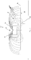
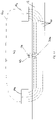
- Figures 1 and 2 depict system 10 and associated method for detecting a material discontinuity in a magnetisable article.
- material discontinuity throughout this specification is intended to include any discontinuity in the material of the article such a crack, spall, pit, weld, coupling or embedding of a device or sensor to or in the article, or any other material property change in the article, whether or not the discontinuity penetrates the surface of the article.
- the magnetisable article is a rail 12 of a railway track.
- the rail 12 is shown side on and has an upper tread surface 14.
- the system 10 has a sensor unit 16 which includes a magnet 18 and at least one magnetic field coupling sensor S.
- the magnet 18 is orientated so that its north pole faces the tread surface 14.
- the system 10 supports the magnet 18 a fixed height above the tread surface 14. Lines of magnetic flux 22 loop from the North Pole to the South Pole.
- the magnet 18 is supported a distance above the rail 12 so that the lines of magnetic flux 22 loop through the rail 12.
- the magnetic field of the magnet 18 causes the surface 14 of the rail 12 directly below the magnet 18 to become polarised opposite to the facing pole of the magnet 18 and the regions distant from the magnet 18 to become inversely polarised.
- a natural boundary 24 is created in the surface 14 at any one instant in time in the vicinity of the magnet 18 where the magnetic polarisation transitions from North to South.
- the coupling sensor S is placed and held at a fixed position relative to and in the active magnetic field of the magnet 18.
- the coupling sensor S which may be a Hall Effect sensor is able to sense characteristics of the flux 22.
- the characteristics include one or preferably both of the direction of the flux 22 and the flux density or field strength. This in effect measures the flux coupling between the rail 12 and the magnet 18.
- the sensor unit 16 of the system 10 is traversed along the length direction of the rail 12. Signals from the coupling sensor S are fed to an analysis system 20 which can conduct various operations on the signals. This includes recording the signal (magnetic field) strength along the rail 12 for example as shown in Figure 3 and/or conducting mathematical operations on the signal to determine whether the signal is representative of a material discontinuity and if so, the type of discontinuity.
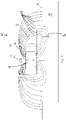
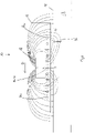
- Figure 2 represents the system 10 at an instant of time traversing a material discontinuity 30 in the rail 12.
- the discontinuity is in the form of a break or crack in the rail.
- the discontinuity/crack 30 creates an artificial polarisation boundary 24a in the rail 12.
- the effective shift in the polarisation boundary from the natural boundary 24 to the artificial boundary 24a created by the crack 30 distorts the flux 22 of the active magnetic field sensed by the sensor S producing a change in the flux coupling between the magnet 18 and the rail 12.
- the distortion may be in terms of both the direction of the magnetic flux and its density. In particular the density is expected to be higher or concentrated near the edges of the discontinuity/crack 30.
- the curve C2 in Figure 3 is representative of the magnetic flux coupling (i.e. flux signature) across and in the immediate vicinity of the discontinuity/crack 30.
- the signature shows a significant disturbance or variation in comparison to the curve C1.
- the signature may be analysed or compared with empirically derived result to enable a determination as to the nature of the specific material discontinuity.
- the analysis system 20 incorporated in the system 10 may analyse the signature C2 to characterise a discontinuity on the basis of features such as the amplitude of the disturbance and the width of the disturbance.
- the analysis system 20 which is arranged to process the signals from the sensor(s) and provide an indication of the change in material properties may perform at least the following signal processing step:
- System 10 can detect material discontinuities such as, but not limited to surface penetrating cracks which may have a width in the order of about 0.1mm or more, a change in material composition such as would arise from a weld in the rail 12 or a device in the or in-line with the rail such as a switch.
- the magnet 18 may produce a magnetic field of about 0.023 tesla at a point where passes it through the sensor(s) S, with the sensor(s) S being spaced about 40mm above the article 12 and about 40mm to the side of the magnet 18.
- the magnet 18 itself may be about 20 mm above the article 12.
- the sensor unit 16 may be traversed at a speed of between 0-140m/s.
- FIG. 10 illustrates a general arrangement for measuring flux leakage.
- lines of flux 40 circulate through magnet M1, the article/rail 12, magnet M2, and free air 42.
- the rail has a surface defect, e.g. a spall 30a causing a leakage path 45 of flux from and back to the rail 12.
- the flux leaked from the rail is sensed by a sensor 44.
- This is to be contrast with the example of the current system 10 where it is the flux coupling though the air between the rail 12 and the magnet 18 that is being ended and used to determine the existence of a material discontinuity.
- Enhanced results may be obtained by providing an array of coupling sensors S0-S10 (herein after referred to in general "sensors Sn”) rather than a single coupling sensor S.
- the array of coupling sensors Sn would be arranged in a line transverse to the direction of movement of the sensing unit 16 as shown in Figure 4 .
- the array of coupling sensors Sn is arranged to extend transversely across the tread surface 14.
- the curve C2 in Figure 3 shows magnetic flux strength (i.e. flux coupling) measures against displacement and in the immediate vicinity of the discontinuity/crack 30.
- Displacement can be measured one of several traditional ways such as by using GPS, wheel tacho readings or velocity measurement against time.
- the disclosed system 10 and associated method may be further enhanced to facilitate an estimation of spatial displacement in the direction of travel across the artificial boundary 30 solely by way of time and magnetic field measurement. This therefore does away with the need for on-board GPS, wheel tacos or velocity measurements.
- Figure 5 illustrates an enhanced system 10a according to the invention which creates its own spatial domain, in combination with the array of coupling sensors Sn of the example shown in Fig 4 .
- the system 10a comprises a magnetic field measuring system arranged to sense magnetic field strength at multiple spaced locations in a length direction D of the article which in this example is the rail 12.
- the magnetic field measuring system is in the form of an array of displacement sensors B0-B10 (herein after referred to in general "displacement sensors Bn").
- the length direction D is either of the opposite directions that run parallel to the length of the rail 12.
- the sensor unit 16 is arranged to collect readings from each of the sensors Bn at each sampling instant.
- the displacement sensors Bn may be in the form of Hall Effect sensors.
- the array of displacement sensors Bn is arranged parallel to the direction D and disposed within the unit 16 so as to lie along a centre line of the rail 12. It should be understood however that the array of displacement sensors Bn does not necessarily need to be along the centre line of the rail 12 or other article in relation to which the system 10 is used.
- the purpose of the array of sensors Bn is to provide an estimate of displacement of the unit 16 with reference to the presence of the discontinuity/crack 30.
- the magnetic field coupling/strength measured from the sensors Bn at one sampling instant is plotted on Figure 6 on a waveform that would arise from a field strength measurement in the vicinity of the discontinuity/crack 30.
- the line F represents the centre line of the discontinuity/crack 30.
- the system 10a is located in a position such that the discontinuity/crack 30 is in a region between the sensors B7 and B8.
- the system 10a does not receive any speed or displacement information from external sources.
- the coupling sensors Sn capture magnetic field strength/coupling measurements at each sampling time. This can be used to categorize the magnetic signature of the coupled magnetic field and thus enable characterisation of the discontinuity/crack 30 in terms of its transverse width, length and its depth. However, without knowing how far the unit 16 travels at each sampling instant determining characteristics of the magnetic field coupling and therefore the width characteristics in the discontinuity/crack 30 in direction of D becomes problematic.
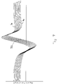
- Figure 7 depicts reconstructed spatially based signals from each of the sensors Sn, as the unit 16 passes over the discontinuity/crack 30 in the rail 12.
- the change in the magnetic field measurement from the sensor unit 16 enables determination of displacement of the waveform shown in Fig. 2 through the sensor array Bn and therefore the distance that the unit 16 is moved down the rail 18.
- the discontinuity/crack 30 can be classified (e.g. broken rail, spall, etc.) on the information in this reconstructed set of signals.
- Processing the signals received from the displacement sensors Bn at sequential sampling times enables determination, or at least a prediction, of the distance travelled by the unit 16 between excessive sampling times. This enables the reconstruction of the signals received from the coupling sensors Sn in the displacement domain which in turn enables width information, and therefore classification, of the discontinuity/crack 30, for example as a broken rail.
- Figures 8a - 8b illustrate one processing method for using the measurements derived from the displacement sensors Bn at successive sampling instants to determine displacement.
- Figure 8a depicts the magnetic field strength in the active magnetic field as measured by each of the sensors Bn at one sampling instant.
- the points B0-B10 in Figure 8a depict the field strength/coupling of the magnetic field across the discontinuity/crack 30 sensed by the respective sensors.
- Figure 8a is depicting the magnetic signature of the discontinuity/crack 30 at one instant in time.
- the next stage in the processing of the signals to determine displacement is to fit a curve between the sample points B0-B10. In this example this is by way of cubic spline interpolation between sample points shown in Figure 8b .
- the distance ⁇ x being the horizontal distance along the cubic spline between the magnetic field strength measurements of the same sensor Bn is not known. This is the same as the physical displacement of the unit 16 between successive sampling times.
- One possible processing technique or method is to cross correlate the sample set within the cubic spline until the correlation error is minimised. The amount of shift at the point of minimum correlation error is equivalent to the estimated shift ⁇ x.
- both ⁇ x is known and the sampling frequency is known.
- This also allows for estimated speed of travel of the unit 16 to be computed. It should be recognised that this speed is computed without the need of external inputs from the vehicle (for example to which the system 10a is attached).
- the system 10a enables estimation of both the distance travelled by the unit 16 between successive sampling times and the overall linear speed of the unit 16. Nevertheless if desired and particularly if readily available from existing on-board equipment distance data or calculations derived externally of the system 10a may be used in addition to that from the system 10a to provide error checking or auditing.
- this process will only be accurate when there is a discontinuity/crack 30 that can be sensed by the unit 16. If there is no discontinuity/crack 30 or other feature to produce a change in flux coupling in the active magnetic field then this process breaks down and does not provide reliable or useful information. However, this is of no consequence in a practical sense. The reason for this is that if there is no magnetic flux coupling variation to sense then there is no discontinuity/crack 30 in the track that is of concern.
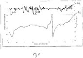
- Figure 9 shows a set of test results where unit 16 is moved sequentially by a known distance of one millimetre between sampling times compared with the resultant distance as measured or estimated by an embodiment of the present method and system.
- Wave C1 is the magnetic flux measured along a four (4) meter section of rail 12 and having a discontinuity/crack 30.
- the discontinuity/crack 30 produces the spike in the wave C1.
- On the left hand side is a scale showing predicted displacement utilising the disclosed system and method. The actual displacement is one millimetre.
- the estimated displacement is shown by the curve C2. This shows a maximum error of about 0.18 millimetres in a region where there is little variation in a magnetic field signature. However, in the region where the spike in the wave C1 exists, the estimated displacement is extremely close to the 1 millimetre known displacement. As previously mentioned lack of accuracy in regions where there is no significant spike or change in the magnetic field strength is of little practical value.
- the sensor array Bn which enables spatial displacement measurement/estimation and the active field array of sensors Sn are independent of each other in terms of their operation and the information/data that they provide.
- the sensor array Sn can be used for example with traditional displacement measurement systems instead with the sensor array Bn.
- the sensor array Bn can be used totally independently as a stand-alone method and system of estimating spatial displacement with respect to a magnetic response associated with an anomaly in an article.
- the method of comprises: applying a magnetic field to an article such as but not limited to a rail 12 or a rail wheel; acquiring multiple magnetic field samples at a known sampling frequency of a magnetic response of the article on or to the applied magnetic field; in a period between the successive sampling instants moving an apparatus capable of acquiring the samples relative to the article; and processing the acquired multiple samples to provide an estimate of the displacement of the apparatus between successive sampling instants.
- the corresponding system for estimating spatial displacement with respect to a magnetic response of an article to an applied magnetic field comprises: an apparatus supporting a magnetic field measuring system arranged to sense magnetic field characteristics at multiple spaced locations in a length direction of the article at each sampling instant of a known sampling frequency, the apparatus being capable of being moved in the length direction along the article; and a processor arranged to process the measured magnetic field strength at the multiple locations at successive sampling instants to provide an estimate of displacement of the apparatus at each sampling instant relative to the magnetic field.
- Figs 1 , 2 , 4 and 5 show the sensors Sn, Bn as being located to the side of the magnet 18. However they may be arrange symmetrically below the magnet 18 in the unit 16 as shown in Fig 11 . Thus in this embodiment the sensors lie between the magnet 18 and the rail 12.
- the relative location of the magnet(s) and the sensors in the active magnetic field produced by the magnet(s) is not critical to embodiments of the system and associated method. The only practical limitation is, given that magnetic field strength decreases with the square of distance, that the sensors should be close enough or the field strength sufficient so that variations in coupling are within the measurement sensitivity of the sensors Sn, Bn.
- Figure 12 shows a system 10b having two magnets 18 and 18b between which one or both arrays of sensors Sn, Bn can be located.
- embodiments of the system 10a may be provided with a rectangular (i.e. including square) matrix of sensors Bn, Sn having two or more linear arrays of sensors Sn and/or Bn.
- an embodiment of the system 10a may have a square 11x11 array of sensors. Signals from sensors in transverse arrays are processed as coupling sensors Sn as describes above, while signals form the longitudinal arrays are processed as displacement sensors Bn as described above. It is believed that this would provide enhanced this will provide enhanced accuracy and characterization of material discontinuities. Implementation of this embodiment will require additional sensors and processing.
Landscapes
- Chemical & Material Sciences (AREA)
- General Health & Medical Sciences (AREA)
- Pathology (AREA)
- Physics & Mathematics (AREA)
- Health & Medical Sciences (AREA)
- Life Sciences & Earth Sciences (AREA)
- Analytical Chemistry (AREA)
- Electrochemistry (AREA)
- General Physics & Mathematics (AREA)
- Biochemistry (AREA)
- Immunology (AREA)
- Chemical Kinetics & Catalysis (AREA)
- Investigating Or Analyzing Materials By The Use Of Magnetic Means (AREA)
- Measurement Of Length, Angles, Or The Like Using Electric Or Magnetic Means (AREA)
- Geophysics And Detection Of Objects (AREA)
- Measuring Magnetic Variables (AREA)
Claims (9)
- Verfahren zum Erkennen einer Materialdiskontinuität (30) in einem magnetisierbaren Gegenstand, umfassend:Bewegen eines Magneten (18) entlang des Gegenstands, so dass die Linien des magnetischen Flusses (22) von einem aktiven Magnetfeld des Magneten den Gegenstand durchlaufen und den Magneten magnetisch mit dem Gegenstand koppeln;Platzieren wenigstens eines Magnetfeldkopplungssensors (S; Sn) an einer festen Position relativ zum Magneten (18) und im aktiven Magnetfeld des Magneten (18), wobei der wenigstens eine Kopplungssensor (S; Sn) mit dem Magneten (18) entlang des Gegenstands wandert, um die magnetische Kopplung zwischen dem Magneten (18) und dem Gegenstand zu messen;Analysieren der gemessenen magnetischen Kopplung im aktiven Magnetfeld auf eine Änderung der magnetischen Kopplung während des Durchlaufs des Magneten (18) und Heranziehen der Änderung der magnetischen Kopplung, um eine Diskontinuität (30) im Gegenstand zu erkennen;Erfassen von Längsmessungen des Magnetfelds entlang des Gegenstands von Verschiebungssensoren (Bn) gleichzeitig mit dem Erfassen von Messungen der magnetischen Kopplung von einem oder mehreren Kopplungssensoren (S; Sn);zwischen den Zeitpunkten, zu denen die Messungen erfasst werden, Bewegen des Magneten (18), des wenigstens einen Kopplungssensors (S; Sn) und der Verschiebungssensoren (Bn) in einer festen Nebeneinanderstellung relativ zueinander entlang des Gegenstands; undHeranziehen der Messungen der Verschiebungssensoren (Bn), um eine Schätzung der Verschiebung des Magneten (18) entlang des Gegenstands zwischen aufeinanderfolgenden Messzeitpunkten zu erhalten.
- Verfahren gemäß Anspruch 1, wobei das Analysieren der Informationen umfasst, die Größe der Diskontinuität (30) zu bestimmen.
- Verfahren gemäß Anspruch 1 oder 2, wobei der wenigstens eine Kopplungssensor (S; Sn) so angeordnet ist, dass er wenigstens die Richtung des magnetischen Flusses (22), der durch den Gegenstand verläuft, erfasst.
- Verfahren gemäß einem der Ansprüche 1 bis 3, wobei der wenigstens eine Kopplungssensor (S; Sn) so angeordnet ist, dass er wenigstens die Dichte des magnetischen Flusses (22), der durch den Gegenstand verläuft, erfasst.
- Verfahren gemäß einem der Ansprüche 1 bis 4, wobei der Gegenstand eine Schiene (12) für ein Schienentransportfahrzeug ist.
- Verfahren gemäß Anspruch 1, wobei das Heranziehen der Messungen der Verschiebungssensoren (Bn), um eine Schätzung der Verschiebung des Magneten (18) bereitzustellen, das Kreuzkorrelieren der Messungen, die von den Verschiebungssensoren (Bn) erfasst wurden, zu aufeinanderfolgenden Messzeitpunkten umfasst.
- Verfahren gemäß Anspruch 6, umfassend, die Messungen von dem wenigstens einen Kopplungssensor (S; Sn) und den Verschiebungssensoren (Bn) zu kombinieren, um eine Anzeige der Magnetfeldkopplung über eine Diskontinuität im Verschiebungsbereich bereitzustellen.
- System (10a) zum Erkennen einer Materialdiskontinuität (30) in einem magnetisierbaren Gegenstand, umfassend:einen Magneten (18), der entlang des Gegenstandes verschoben werden kann, so dass die Linien des magnetischen Flusses (22) von einem aktiven Magnetfeld des Magneten den Gegenstand durchlaufen und den Magneten (18) magnetisch mit dem Gegenstand koppeln;Verschiebungssensoren (Bn) und wenigstens einen Magnetfeldkopplungssensor (S; Sn), die an einer festen Position relativ zum Magneten (18) und im aktiven Magnetfeld des Magneten (18) angeordnet sind,wobei der wenigstens eine Kopplungssensor (S; Sn) mit dem Magneten (18) entlang des Gegenstands wandert und dafür ausgelegt ist, die magnetische Kopplung zwischen dem Magneten (18) und dem Gegenstand zu messen;ein System zur Analyse des magnetischen Flusses, das so angeordnet ist, dass es Informationen bezüglich des magnetischen Flusses (22) analysiert, die von dem wenigstens einen Kopplungssensor (S; Sn) bereitgestellt werden, um einen Hinweis auf eine Charakteristik der die Oberfläche durchdringenden Diskontinuität (30) zu liefern; undwobei die Verschiebungssensoren (Bn) dafür ausgelegt sind, Messungen des Magnetfelds an mehreren in Längsrichtung entlang des Gegenstands beabstandeten Stellen gleichzeitig mit der Erfassung von Messungen der magnetischen Kopplung von den ein oder mehreren Kopplungssensoren (S; Sn) zu erfassen; unddas System dafür ausgelegt ist, die Messungen von den Verschiebungssensoren (Bn) heranzuziehen, um eine Schätzung der Verschiebung des Magneten (18) entlang des Gegenstands zwischen aufeinanderfolgenden Messzeitpunkten bereitzustellen.
- System gemäß Anspruch 8, wobei der wenigstens eine Magnetfeldkopplungssensor (S) einer von mehreren Kopplungssensoren (Sn) ist, die in einer Anordnung in einer Richtung quer zu einer Verschiebungsrichtung des Magneten (18) entlang des Gegenstands angeordnet sind.
Applications Claiming Priority (2)
| Application Number | Priority Date | Filing Date | Title |
|---|---|---|---|
| AU2015903531A AU2015903531A0 (en) | 2015-08-31 | A method and system for detecting a material discontinuity in a magnetisable article | |
| PCT/AU2016/050821 WO2017035591A1 (en) | 2015-08-31 | 2016-08-31 | A method and system for detecting a material discontinuity in a magnetisable article |
Publications (3)
| Publication Number | Publication Date |
|---|---|
| EP3344982A1 EP3344982A1 (de) | 2018-07-11 |
| EP3344982A4 EP3344982A4 (de) | 2019-08-14 |
| EP3344982B1 true EP3344982B1 (de) | 2022-10-26 |
Family
ID=58186330
Family Applications (1)
| Application Number | Title | Priority Date | Filing Date |
|---|---|---|---|
| EP16840420.0A Active EP3344982B1 (de) | 2015-08-31 | 2016-08-31 | Verfahren und system zur erkennung einer materialdiskontinuität bei einem magnetisierbaren artikel |
Country Status (12)
| Country | Link |
|---|---|
| US (1) | US11249047B2 (de) |
| EP (1) | EP3344982B1 (de) |
| CN (1) | CN108431591B (de) |
| AU (1) | AU2016314771B2 (de) |
| BR (1) | BR112018003658B1 (de) |
| CA (1) | CA2996849C (de) |
| CL (1) | CL2018000531A1 (de) |
| CO (1) | CO2018002442A2 (de) |
| ES (1) | ES2933036T3 (de) |
| RU (1) | RU2697061C1 (de) |
| WO (1) | WO2017035591A1 (de) |
| ZA (1) | ZA201801343B (de) |
Families Citing this family (5)
| Publication number | Priority date | Publication date | Assignee | Title |
|---|---|---|---|---|
| WO2020217278A1 (ja) * | 2019-04-22 | 2020-10-29 | 三菱電機株式会社 | 磁性体探傷装置 |
| CN110239591A (zh) * | 2019-07-10 | 2019-09-17 | 广州铁路科技开发有限公司 | 一种磁轨枕检测装置 |
| KR102256282B1 (ko) * | 2019-12-06 | 2021-05-27 | 한국로봇융합연구원 | 배관결함 분석장치 |
| CN111579637B (zh) * | 2020-06-11 | 2022-04-29 | 哈尔滨工业大学(深圳)(哈尔滨工业大学深圳科技创新研究院) | 一种检测及区分钢丝绳内外缺陷的无损检测方法和装置 |
| CN115871738B (zh) * | 2023-01-31 | 2024-07-23 | 北京安润通电子技术开发有限公司 | 一种计轴和断轨检测一体化传感器结构及使用方法 |
Family Cites Families (27)
| Publication number | Priority date | Publication date | Assignee | Title |
|---|---|---|---|---|
| US2958818A (en) * | 1957-05-01 | 1960-11-01 | Sperry Prod Inc | Rail flaw detector mechanism |
| SU421728A1 (ru) | 1968-10-18 | 1974-03-30 | Е. И. Успенский , В. Л. Байдаков | Искательная система магнитного вагона- дефектоскопа |
| US3820016A (en) * | 1972-07-03 | 1974-06-25 | M Gieskieng | Method and apparatus for the detection of cracks and flaws in rail wheels,rails and the like by sliding a prerecorded magnetic medium over the test piece |
| EP0193168A3 (de) * | 1985-02-25 | 1989-01-25 | Kubota Limited | Verfahren zur Prüfung der Karburisierung und Sonde dafür |
| US5105151A (en) | 1990-10-02 | 1992-04-14 | Kubota Corporation | Method and apparatus for magnetically detecting a carburized portion of an article while discriminating a non-carburized deteriorated layer of the article |
| US5336998A (en) * | 1992-06-22 | 1994-08-09 | United States Pipe And Foundry Company | Sensor for detecting faults in a magnetized ferrous object using hall effect elements |
| EP0624793A1 (de) | 1993-05-03 | 1994-11-17 | Tuboscope Vetco (Deutschland) Gmbh | Verfahren und Gerät zur Ermittlung von magnetischen Unstetigkeiten in einer Probe aus magnetisierbarem Material |
| US5786750A (en) * | 1996-05-10 | 1998-07-28 | The United States Of America As Represented By The Secretary Of The Navy | Pilot vehicle which is useful for monitoring hazardous conditions on railroad tracks |
| AUPN992596A0 (en) | 1996-05-17 | 1996-06-13 | Technological Resources Pty Limited | Magnetic detection of discontinuities in magnetic materials |
| US6150809A (en) * | 1996-09-20 | 2000-11-21 | Tpl, Inc. | Giant magnetorestive sensors and sensor arrays for detection and imaging of anomalies in conductive materials |
| WO2002030729A1 (en) * | 2000-10-10 | 2002-04-18 | Sperry Rail, Inc. | Hi-rail vehicle-based rail inspection system |
| US6768298B2 (en) | 2001-07-17 | 2004-07-27 | Transportation Technology Center, Inc. | Transverse crack detection in rail head using low frequency eddy currents |
| US7038445B2 (en) * | 2002-08-28 | 2006-05-02 | Scan Systems, Corp. | Method, system and apparatus for ferromagnetic wall monitoring |
| JP2004279372A (ja) | 2003-03-19 | 2004-10-07 | Yazaki Corp | 破断検出方法 |
| US7521917B2 (en) * | 2004-06-25 | 2009-04-21 | General Electric Company | Method and apparatus for testing material integrity |
| DE102004054423B3 (de) * | 2004-11-10 | 2006-05-04 | Fraunhofer-Gesellschaft zur Förderung der angewandten Forschung e.V. | Vorrichtung zur Materialprüfung und/oder Dickenmessung an einem wenigstens elektrisch leitende und ferromagnetische Materialanteile aufweisenden Prüfobjekt |
| US7519487B2 (en) * | 2006-03-06 | 2009-04-14 | Technion Research And Development Foundation Ltd. | System and method for depth determination of cracks in conducting structures |
| WO2008054056A1 (en) * | 2006-11-01 | 2008-05-08 | Industry-Academic Cooperation Foundation, Chosun University | Magnetic sensor array and apparatus for detecting defect using the magnetic sensor array |
| GB0722534D0 (en) | 2007-11-16 | 2007-12-27 | Advanced Eng Solutions Ltd | Pipeline condition detecting method and apparatus |
| US8423240B2 (en) * | 2008-06-30 | 2013-04-16 | International Electronic Machines Corporation | Wireless railroad monitoring |
| US8368395B2 (en) | 2008-12-17 | 2013-02-05 | Ndt Technologies, Inc. | Magnetic inspection device and method for detecting loss in metallic cross section |
| US8914171B2 (en) * | 2012-11-21 | 2014-12-16 | General Electric Company | Route examining system and method |
| AU2011226745B2 (en) | 2010-03-10 | 2016-01-14 | Robel Holding Gmbh | Method and apparatus for magnetic crack depth prediction |
| US9162691B2 (en) * | 2012-04-27 | 2015-10-20 | Transportation Technology Center, Inc. | System and method for detecting broken rail and occupied track from a railway vehicle |
| WO2014193610A1 (en) * | 2013-05-30 | 2014-12-04 | Wabtec Holding Corp. | Broken rail detection system for communications-based train control |
| WO2015120550A1 (en) * | 2014-02-11 | 2015-08-20 | Pure Technologies Ltd. | Method and system for non-destructive rail inspection |
| US9701326B2 (en) * | 2014-09-12 | 2017-07-11 | Westinghouse Air Brake Technologies Corporation | Broken rail detection system for railway systems |
-
2016
- 2016-08-31 EP EP16840420.0A patent/EP3344982B1/de active Active
- 2016-08-31 CA CA2996849A patent/CA2996849C/en active Active
- 2016-08-31 US US15/755,766 patent/US11249047B2/en active Active
- 2016-08-31 WO PCT/AU2016/050821 patent/WO2017035591A1/en not_active Ceased
- 2016-08-31 CN CN201680063426.9A patent/CN108431591B/zh active Active
- 2016-08-31 AU AU2016314771A patent/AU2016314771B2/en active Active
- 2016-08-31 RU RU2018111320A patent/RU2697061C1/ru active
- 2016-08-31 ES ES16840420T patent/ES2933036T3/es active Active
- 2016-08-31 BR BR112018003658-7A patent/BR112018003658B1/pt active IP Right Grant
-
2018
- 2018-02-27 CL CL2018000531A patent/CL2018000531A1/es unknown
- 2018-02-27 ZA ZA2018/01343A patent/ZA201801343B/en unknown
- 2018-03-05 CO CONC2018/0002442A patent/CO2018002442A2/es unknown
Also Published As
| Publication number | Publication date |
|---|---|
| CL2018000531A1 (es) | 2018-08-03 |
| BR112018003658B1 (pt) | 2022-03-15 |
| CN108431591B (zh) | 2022-07-22 |
| ZA201801343B (en) | 2018-12-19 |
| CO2018002442A2 (es) | 2018-05-21 |
| AU2016314771A1 (en) | 2018-03-15 |
| EP3344982A4 (de) | 2019-08-14 |
| AU2016314771B2 (en) | 2018-11-08 |
| BR112018003658A2 (pt) | 2018-09-25 |
| US20180328888A1 (en) | 2018-11-15 |
| CA2996849A1 (en) | 2017-03-09 |
| EP3344982A1 (de) | 2018-07-11 |
| CA2996849C (en) | 2023-08-01 |
| CN108431591A (zh) | 2018-08-21 |
| ES2933036T3 (es) | 2023-01-31 |
| US11249047B2 (en) | 2022-02-15 |
| WO2017035591A1 (en) | 2017-03-09 |
| RU2697061C1 (ru) | 2019-08-09 |
Similar Documents
| Publication | Publication Date | Title |
|---|---|---|
| Papaelias et al. | High-speed inspection of rails using ACFM techniques | |
| Xu et al. | Study on high-speed rail defect detection methods based on ECT, MFL testing and ACFM | |
| JP4829883B2 (ja) | 管を非破壊検査するための方法及び装置 | |
| CN103163216B (zh) | 一种基于巨磁电阻传感器的金属导体缺陷识别及估计方法 | |
| US20120253696A1 (en) | Methods and apparatus for the inspection of plates and pipe walls | |
| CA2996849C (en) | A method and system for detecting a material discontinuity in a magnetisable article | |
| AU2018213965A1 (en) | Method and system for non-destructive rail inspection | |
| GB2492745A (en) | Magnetic flux leakage inspection | |
| Jarvis et al. | Performance evaluation of a magnetic field measurement NDE technique using a model assisted Probability of Detection framework | |
| RU2724582C1 (ru) | Способ бесконтактного выявления наличия, месторасположения и степени опасности концентраторов механических напряжений в металле ферромагнитных сооружений | |
| CA2965105C (en) | Method and apparatus for material identification of pipelines and other tubulars | |
| CN112083059A (zh) | 一种滤除钢轨顶面提离干扰的方法 | |
| WO2022214694A1 (en) | Method of and system for detecting and/or monitoring the growth of defects | |
| Rocha et al. | Sub-surface defect detection with motion induced eddy currents in aluminium | |
| Feng et al. | Study on the lowest spatial resolution of magnetic flux leakage testing for weld cracks | |
| JP2004294341A (ja) | パルスリモートフィールド渦電流による探傷方法及びその探傷装置 | |
| RU2491541C1 (ru) | Магнитный дефектоскоп стальных канатов | |
| CN107576720A (zh) | 铁磁细长构件浅层损伤磁发射检测方法及磁发射检测系统 | |
| RU2229707C1 (ru) | Способ магнитного контроля трубопроводов | |
| RU2645830C1 (ru) | Измеритель магнитного дефектоскопа протяженного изделия сложной формы | |
| Tian et al. | Eddy-current model and detection in a thick stainless steel plate | |
| Higgins | Non-destructive testing of suspender ropes with magnetostriction | |
| Ramos et al. | Eddy current nondestructive testing using faraday induction to produce the excitation | |
| Ahemadi et al. | Development of a MFL system with optical positioning for ferromagnetic plate inspection | |
| Yang et al. | Novel Nanocrystalline Alloy Symmetrical Magnetic Focused Eddy Current Array Sensing for Microcrack Detection |
Legal Events
| Date | Code | Title | Description |
|---|---|---|---|
| STAA | Information on the status of an ep patent application or granted ep patent |
Free format text: STATUS: THE INTERNATIONAL PUBLICATION HAS BEEN MADE |
|
| PUAI | Public reference made under article 153(3) epc to a published international application that has entered the european phase |
Free format text: ORIGINAL CODE: 0009012 |
|
| STAA | Information on the status of an ep patent application or granted ep patent |
Free format text: STATUS: REQUEST FOR EXAMINATION WAS MADE |
|
| 17P | Request for examination filed |
Effective date: 20180227 |
|
| AK | Designated contracting states |
Kind code of ref document: A1 Designated state(s): AL AT BE BG CH CY CZ DE DK EE ES FI FR GB GR HR HU IE IS IT LI LT LU LV MC MK MT NL NO PL PT RO RS SE SI SK SM TR |
|
| AX | Request for extension of the european patent |
Extension state: BA ME |
|
| DAV | Request for validation of the european patent (deleted) | ||
| DAX | Request for extension of the european patent (deleted) | ||
| REG | Reference to a national code |
Ref country code: DE Ref legal event code: R079 Ref document number: 602016075946 Country of ref document: DE Free format text: PREVIOUS MAIN CLASS: G01N0027720000 Ipc: G01N0027830000 |
|
| A4 | Supplementary search report drawn up and despatched |
Effective date: 20190711 |
|
| RIC1 | Information provided on ipc code assigned before grant |
Ipc: G01N 27/83 20060101AFI20190705BHEP |
|
| RAP1 | Party data changed (applicant data changed or rights of an application transferred) |
Owner name: SIEMENS MOBILITY PTY LTD. |
|
| GRAP | Despatch of communication of intention to grant a patent |
Free format text: ORIGINAL CODE: EPIDOSNIGR1 |
|
| STAA | Information on the status of an ep patent application or granted ep patent |
Free format text: STATUS: GRANT OF PATENT IS INTENDED |
|
| INTG | Intention to grant announced |
Effective date: 20220623 |
|
| GRAS | Grant fee paid |
Free format text: ORIGINAL CODE: EPIDOSNIGR3 |
|
| GRAA | (expected) grant |
Free format text: ORIGINAL CODE: 0009210 |
|
| STAA | Information on the status of an ep patent application or granted ep patent |
Free format text: STATUS: THE PATENT HAS BEEN GRANTED |
|
| AK | Designated contracting states |
Kind code of ref document: B1 Designated state(s): AL AT BE BG CH CY CZ DE DK EE ES FI FR GB GR HR HU IE IS IT LI LT LU LV MC MK MT NL NO PL PT RO RS SE SI SK SM TR |
|
| REG | Reference to a national code |
Ref country code: GB Ref legal event code: FG4D |
|
| REG | Reference to a national code |
Ref country code: CH Ref legal event code: EP |
|
| REG | Reference to a national code |
Ref country code: DE Ref legal event code: R096 Ref document number: 602016075946 Country of ref document: DE |
|
| REG | Reference to a national code |
Ref country code: AT Ref legal event code: REF Ref document number: 1527369 Country of ref document: AT Kind code of ref document: T Effective date: 20221115 |
|
| REG | Reference to a national code |
Ref country code: IE Ref legal event code: FG4D |
|
| REG | Reference to a national code |
Ref country code: ES Ref legal event code: FG2A Ref document number: 2933036 Country of ref document: ES Kind code of ref document: T3 Effective date: 20230131 |
|
| REG | Reference to a national code |
Ref country code: LT Ref legal event code: MG9D |
|
| REG | Reference to a national code |
Ref country code: NL Ref legal event code: MP Effective date: 20221026 |
|
| REG | Reference to a national code |
Ref country code: AT Ref legal event code: MK05 Ref document number: 1527369 Country of ref document: AT Kind code of ref document: T Effective date: 20221026 |
|
| PG25 | Lapsed in a contracting state [announced via postgrant information from national office to epo] |
Ref country code: NL Free format text: LAPSE BECAUSE OF FAILURE TO SUBMIT A TRANSLATION OF THE DESCRIPTION OR TO PAY THE FEE WITHIN THE PRESCRIBED TIME-LIMIT Effective date: 20221026 |
|
| PG25 | Lapsed in a contracting state [announced via postgrant information from national office to epo] |
Ref country code: SE Free format text: LAPSE BECAUSE OF FAILURE TO SUBMIT A TRANSLATION OF THE DESCRIPTION OR TO PAY THE FEE WITHIN THE PRESCRIBED TIME-LIMIT Effective date: 20221026 Ref country code: PT Free format text: LAPSE BECAUSE OF FAILURE TO SUBMIT A TRANSLATION OF THE DESCRIPTION OR TO PAY THE FEE WITHIN THE PRESCRIBED TIME-LIMIT Effective date: 20230227 Ref country code: NO Free format text: LAPSE BECAUSE OF FAILURE TO SUBMIT A TRANSLATION OF THE DESCRIPTION OR TO PAY THE FEE WITHIN THE PRESCRIBED TIME-LIMIT Effective date: 20230126 Ref country code: LT Free format text: LAPSE BECAUSE OF FAILURE TO SUBMIT A TRANSLATION OF THE DESCRIPTION OR TO PAY THE FEE WITHIN THE PRESCRIBED TIME-LIMIT Effective date: 20221026 Ref country code: FI Free format text: LAPSE BECAUSE OF FAILURE TO SUBMIT A TRANSLATION OF THE DESCRIPTION OR TO PAY THE FEE WITHIN THE PRESCRIBED TIME-LIMIT Effective date: 20221026 Ref country code: AT Free format text: LAPSE BECAUSE OF FAILURE TO SUBMIT A TRANSLATION OF THE DESCRIPTION OR TO PAY THE FEE WITHIN THE PRESCRIBED TIME-LIMIT Effective date: 20221026 |
|
| PG25 | Lapsed in a contracting state [announced via postgrant information from national office to epo] |
Ref country code: RS Free format text: LAPSE BECAUSE OF FAILURE TO SUBMIT A TRANSLATION OF THE DESCRIPTION OR TO PAY THE FEE WITHIN THE PRESCRIBED TIME-LIMIT Effective date: 20221026 Ref country code: PL Free format text: LAPSE BECAUSE OF FAILURE TO SUBMIT A TRANSLATION OF THE DESCRIPTION OR TO PAY THE FEE WITHIN THE PRESCRIBED TIME-LIMIT Effective date: 20221026 Ref country code: LV Free format text: LAPSE BECAUSE OF FAILURE TO SUBMIT A TRANSLATION OF THE DESCRIPTION OR TO PAY THE FEE WITHIN THE PRESCRIBED TIME-LIMIT Effective date: 20221026 Ref country code: IS Free format text: LAPSE BECAUSE OF FAILURE TO SUBMIT A TRANSLATION OF THE DESCRIPTION OR TO PAY THE FEE WITHIN THE PRESCRIBED TIME-LIMIT Effective date: 20230226 Ref country code: HR Free format text: LAPSE BECAUSE OF FAILURE TO SUBMIT A TRANSLATION OF THE DESCRIPTION OR TO PAY THE FEE WITHIN THE PRESCRIBED TIME-LIMIT Effective date: 20221026 Ref country code: GR Free format text: LAPSE BECAUSE OF FAILURE TO SUBMIT A TRANSLATION OF THE DESCRIPTION OR TO PAY THE FEE WITHIN THE PRESCRIBED TIME-LIMIT Effective date: 20230127 |
|
| REG | Reference to a national code |
Ref country code: DE Ref legal event code: R097 Ref document number: 602016075946 Country of ref document: DE |
|
| PG25 | Lapsed in a contracting state [announced via postgrant information from national office to epo] |
Ref country code: SM Free format text: LAPSE BECAUSE OF FAILURE TO SUBMIT A TRANSLATION OF THE DESCRIPTION OR TO PAY THE FEE WITHIN THE PRESCRIBED TIME-LIMIT Effective date: 20221026 Ref country code: RO Free format text: LAPSE BECAUSE OF FAILURE TO SUBMIT A TRANSLATION OF THE DESCRIPTION OR TO PAY THE FEE WITHIN THE PRESCRIBED TIME-LIMIT Effective date: 20221026 Ref country code: EE Free format text: LAPSE BECAUSE OF FAILURE TO SUBMIT A TRANSLATION OF THE DESCRIPTION OR TO PAY THE FEE WITHIN THE PRESCRIBED TIME-LIMIT Effective date: 20221026 Ref country code: DK Free format text: LAPSE BECAUSE OF FAILURE TO SUBMIT A TRANSLATION OF THE DESCRIPTION OR TO PAY THE FEE WITHIN THE PRESCRIBED TIME-LIMIT Effective date: 20221026 Ref country code: CZ Free format text: LAPSE BECAUSE OF FAILURE TO SUBMIT A TRANSLATION OF THE DESCRIPTION OR TO PAY THE FEE WITHIN THE PRESCRIBED TIME-LIMIT Effective date: 20221026 |
|
| PG25 | Lapsed in a contracting state [announced via postgrant information from national office to epo] |
Ref country code: SK Free format text: LAPSE BECAUSE OF FAILURE TO SUBMIT A TRANSLATION OF THE DESCRIPTION OR TO PAY THE FEE WITHIN THE PRESCRIBED TIME-LIMIT Effective date: 20221026 Ref country code: AL Free format text: LAPSE BECAUSE OF FAILURE TO SUBMIT A TRANSLATION OF THE DESCRIPTION OR TO PAY THE FEE WITHIN THE PRESCRIBED TIME-LIMIT Effective date: 20221026 |
|
| PLBE | No opposition filed within time limit |
Free format text: ORIGINAL CODE: 0009261 |
|
| STAA | Information on the status of an ep patent application or granted ep patent |
Free format text: STATUS: NO OPPOSITION FILED WITHIN TIME LIMIT |
|
| 26N | No opposition filed |
Effective date: 20230727 |
|
| PG25 | Lapsed in a contracting state [announced via postgrant information from national office to epo] |
Ref country code: SI Free format text: LAPSE BECAUSE OF FAILURE TO SUBMIT A TRANSLATION OF THE DESCRIPTION OR TO PAY THE FEE WITHIN THE PRESCRIBED TIME-LIMIT Effective date: 20221026 |
|
| PG25 | Lapsed in a contracting state [announced via postgrant information from national office to epo] |
Ref country code: MC Free format text: LAPSE BECAUSE OF FAILURE TO SUBMIT A TRANSLATION OF THE DESCRIPTION OR TO PAY THE FEE WITHIN THE PRESCRIBED TIME-LIMIT Effective date: 20221026 |
|
| PG25 | Lapsed in a contracting state [announced via postgrant information from national office to epo] |
Ref country code: MC Free format text: LAPSE BECAUSE OF FAILURE TO SUBMIT A TRANSLATION OF THE DESCRIPTION OR TO PAY THE FEE WITHIN THE PRESCRIBED TIME-LIMIT Effective date: 20221026 |
|
| PG25 | Lapsed in a contracting state [announced via postgrant information from national office to epo] |
Ref country code: LU Free format text: LAPSE BECAUSE OF NON-PAYMENT OF DUE FEES Effective date: 20230831 |
|
| PG25 | Lapsed in a contracting state [announced via postgrant information from national office to epo] |
Ref country code: LU Free format text: LAPSE BECAUSE OF NON-PAYMENT OF DUE FEES Effective date: 20230831 |
|
| REG | Reference to a national code |
Ref country code: BE Ref legal event code: MM Effective date: 20230831 |
|
| REG | Reference to a national code |
Ref country code: IE Ref legal event code: MM4A |
|
| PG25 | Lapsed in a contracting state [announced via postgrant information from national office to epo] |
Ref country code: IE Free format text: LAPSE BECAUSE OF NON-PAYMENT OF DUE FEES Effective date: 20230831 |
|
| PG25 | Lapsed in a contracting state [announced via postgrant information from national office to epo] |
Ref country code: IE Free format text: LAPSE BECAUSE OF NON-PAYMENT OF DUE FEES Effective date: 20230831 |
|
| PG25 | Lapsed in a contracting state [announced via postgrant information from national office to epo] |
Ref country code: BE Free format text: LAPSE BECAUSE OF NON-PAYMENT OF DUE FEES Effective date: 20230831 |
|
| PG25 | Lapsed in a contracting state [announced via postgrant information from national office to epo] |
Ref country code: BG Free format text: LAPSE BECAUSE OF FAILURE TO SUBMIT A TRANSLATION OF THE DESCRIPTION OR TO PAY THE FEE WITHIN THE PRESCRIBED TIME-LIMIT Effective date: 20221026 |
|
| PG25 | Lapsed in a contracting state [announced via postgrant information from national office to epo] |
Ref country code: BG Free format text: LAPSE BECAUSE OF FAILURE TO SUBMIT A TRANSLATION OF THE DESCRIPTION OR TO PAY THE FEE WITHIN THE PRESCRIBED TIME-LIMIT Effective date: 20221026 |
|
| PG25 | Lapsed in a contracting state [announced via postgrant information from national office to epo] |
Ref country code: CY Free format text: LAPSE BECAUSE OF FAILURE TO SUBMIT A TRANSLATION OF THE DESCRIPTION OR TO PAY THE FEE WITHIN THE PRESCRIBED TIME-LIMIT; INVALID AB INITIO Effective date: 20160831 |
|
| PG25 | Lapsed in a contracting state [announced via postgrant information from national office to epo] |
Ref country code: HU Free format text: LAPSE BECAUSE OF FAILURE TO SUBMIT A TRANSLATION OF THE DESCRIPTION OR TO PAY THE FEE WITHIN THE PRESCRIBED TIME-LIMIT; INVALID AB INITIO Effective date: 20160831 |
|
| PGFP | Annual fee paid to national office [announced via postgrant information from national office to epo] |
Ref country code: IT Payment date: 20250827 Year of fee payment: 10 |
|
| PGFP | Annual fee paid to national office [announced via postgrant information from national office to epo] |
Ref country code: GB Payment date: 20250902 Year of fee payment: 10 |
|
| PGFP | Annual fee paid to national office [announced via postgrant information from national office to epo] |
Ref country code: FR Payment date: 20250827 Year of fee payment: 10 |
|
| REG | Reference to a national code |
Ref country code: CH Ref legal event code: U11 Free format text: ST27 STATUS EVENT CODE: U-0-0-U10-U11 (AS PROVIDED BY THE NATIONAL OFFICE) Effective date: 20251110 |
|
| PG25 | Lapsed in a contracting state [announced via postgrant information from national office to epo] |
Ref country code: TR Free format text: LAPSE BECAUSE OF FAILURE TO SUBMIT A TRANSLATION OF THE DESCRIPTION OR TO PAY THE FEE WITHIN THE PRESCRIBED TIME-LIMIT Effective date: 20221026 |
|
| PGFP | Annual fee paid to national office [announced via postgrant information from national office to epo] |
Ref country code: DE Payment date: 20251020 Year of fee payment: 10 |
|
| PGFP | Annual fee paid to national office [announced via postgrant information from national office to epo] |
Ref country code: CH Payment date: 20251110 Year of fee payment: 10 |
|
| PGFP | Annual fee paid to national office [announced via postgrant information from national office to epo] |
Ref country code: ES Payment date: 20251124 Year of fee payment: 10 |