EP3345005B1 - Procédé et dispositif destinés à la prévention d'éclaboussures d'un échantillon de fluide non recouvert pendant le transport sur un équipement de laboratoire de diagnostic - Google Patents
Procédé et dispositif destinés à la prévention d'éclaboussures d'un échantillon de fluide non recouvert pendant le transport sur un équipement de laboratoire de diagnostic Download PDFInfo
- Publication number
- EP3345005B1 EP3345005B1 EP16842629.4A EP16842629A EP3345005B1 EP 3345005 B1 EP3345005 B1 EP 3345005B1 EP 16842629 A EP16842629 A EP 16842629A EP 3345005 B1 EP3345005 B1 EP 3345005B1
- Authority
- EP
- European Patent Office
- Prior art keywords
- patient sample
- disk
- fluid
- pipette
- tube
- Prior art date
- Legal status (The legal status is an assumption and is not a legal conclusion. Google has not performed a legal analysis and makes no representation as to the accuracy of the status listed.)
- Active
Links
Images


Classifications
-
- B—PERFORMING OPERATIONS; TRANSPORTING
- B01—PHYSICAL OR CHEMICAL PROCESSES OR APPARATUS IN GENERAL
- B01L—CHEMICAL OR PHYSICAL LABORATORY APPARATUS FOR GENERAL USE
- B01L3/00—Containers or dishes for laboratory use, e.g. laboratory glassware; Droppers
- B01L3/50—Containers for the purpose of retaining a material to be analysed, e.g. test tubes
- B01L3/508—Rigid containers without fluid transport within
- B01L3/5082—Test tubes per se
- B01L3/50825—Closing or opening means, corks, bungs
-
- G—PHYSICS
- G01—MEASURING; TESTING
- G01N—INVESTIGATING OR ANALYSING MATERIALS BY DETERMINING THEIR CHEMICAL OR PHYSICAL PROPERTIES
- G01N35/00—Automatic analysis not limited to methods or materials provided for in any single one of groups G01N1/00 - G01N33/00; Handling materials therefor
- G01N35/02—Automatic analysis not limited to methods or materials provided for in any single one of groups G01N1/00 - G01N33/00; Handling materials therefor using a plurality of sample containers moved by a conveyor system past one or more treatment or analysis stations
- G01N35/04—Details of the conveyor system
-
- B—PERFORMING OPERATIONS; TRANSPORTING
- B01—PHYSICAL OR CHEMICAL PROCESSES OR APPARATUS IN GENERAL
- B01L—CHEMICAL OR PHYSICAL LABORATORY APPARATUS FOR GENERAL USE
- B01L3/00—Containers or dishes for laboratory use, e.g. laboratory glassware; Droppers
- B01L3/50—Containers for the purpose of retaining a material to be analysed, e.g. test tubes
- B01L3/502—Containers for the purpose of retaining a material to be analysed, e.g. test tubes with fluid transport, e.g. in multi-compartment structures
- B01L3/5021—Test tubes specially adapted for centrifugation purposes
- B01L3/50215—Test tubes specially adapted for centrifugation purposes using a float to separate phases
-
- B—PERFORMING OPERATIONS; TRANSPORTING
- B01—PHYSICAL OR CHEMICAL PROCESSES OR APPARATUS IN GENERAL
- B01L—CHEMICAL OR PHYSICAL LABORATORY APPARATUS FOR GENERAL USE
- B01L3/00—Containers or dishes for laboratory use, e.g. laboratory glassware; Droppers
- B01L3/52—Containers specially adapted for storing or dispensing a reagent
-
- B—PERFORMING OPERATIONS; TRANSPORTING
- B01—PHYSICAL OR CHEMICAL PROCESSES OR APPARATUS IN GENERAL
- B01L—CHEMICAL OR PHYSICAL LABORATORY APPARATUS FOR GENERAL USE
- B01L2200/00—Solutions for specific problems relating to chemical or physical laboratory apparatus
- B01L2200/06—Fluid handling related problems
-
- B—PERFORMING OPERATIONS; TRANSPORTING
- B01—PHYSICAL OR CHEMICAL PROCESSES OR APPARATUS IN GENERAL
- B01L—CHEMICAL OR PHYSICAL LABORATORY APPARATUS FOR GENERAL USE
- B01L2200/00—Solutions for specific problems relating to chemical or physical laboratory apparatus
- B01L2200/14—Process control and prevention of errors
-
- B—PERFORMING OPERATIONS; TRANSPORTING
- B01—PHYSICAL OR CHEMICAL PROCESSES OR APPARATUS IN GENERAL
- B01L—CHEMICAL OR PHYSICAL LABORATORY APPARATUS FOR GENERAL USE
- B01L2200/00—Solutions for specific problems relating to chemical or physical laboratory apparatus
- B01L2200/14—Process control and prevention of errors
- B01L2200/141—Preventing contamination, tampering
-
- G—PHYSICS
- G01—MEASURING; TESTING
- G01N—INVESTIGATING OR ANALYSING MATERIALS BY DETERMINING THEIR CHEMICAL OR PHYSICAL PROPERTIES
- G01N1/00—Sampling; Preparing specimens for investigation
- G01N1/02—Devices for withdrawing samples
- G01N1/10—Devices for withdrawing samples in the liquid or fluent state
- G01N1/14—Suction devices, e.g. pumps; Ejector devices
- G01N2001/1418—Depression, aspiration
-
- G—PHYSICS
- G01—MEASURING; TESTING
- G01N—INVESTIGATING OR ANALYSING MATERIALS BY DETERMINING THEIR CHEMICAL OR PHYSICAL PROPERTIES
- G01N35/00—Automatic analysis not limited to methods or materials provided for in any single one of groups G01N1/00 - G01N33/00; Handling materials therefor
- G01N2035/00178—Special arrangements of analysers
- G01N2035/00277—Special precautions to avoid contamination (e.g. enclosures, glove- boxes, sealed sample carriers, disposal of contaminated material)
-
- G—PHYSICS
- G01—MEASURING; TESTING
- G01N—INVESTIGATING OR ANALYSING MATERIALS BY DETERMINING THEIR CHEMICAL OR PHYSICAL PROPERTIES
- G01N35/00—Automatic analysis not limited to methods or materials provided for in any single one of groups G01N1/00 - G01N33/00; Handling materials therefor
- G01N35/02—Automatic analysis not limited to methods or materials provided for in any single one of groups G01N1/00 - G01N33/00; Handling materials therefor using a plurality of sample containers moved by a conveyor system past one or more treatment or analysis stations
- G01N35/04—Details of the conveyor system
- G01N2035/0401—Sample carriers, cuvettes or reaction vessels
- G01N2035/0403—Sample carriers with closing or sealing means
- G01N2035/0405—Sample carriers with closing or sealing means manipulating closing or opening means, e.g. stoppers, screw caps, lids or covers
Definitions
- the present invention relates, generally, to sample handling in an in vitro diagnostics environment, and more particularly, to materials to be added to fluid samples in an IVD environment.
- Embodiments of the present invention are particularly well suited, but in no way limited, to providing an improved method for facilitating movement of fluid samples in an automation system or sample handling system to minimize or reduce risk of splashing fluid samples.
- Various types of analytical tests related to patient diagnosis and therapy can be performed by analysis of a liquid sample taken from a patient's bodily fluids, or abscesses. These assays are typically conducted with automated clinical analyzers onto which tubes or vials containing patient samples have been loaded. The analyzer extracts a liquid sample from the vial and combines the sample with various reagents in special reaction cuvettes or tubes (referred to generally as reaction vessels). Usually the sample-reagent solution is incubated or otherwise processed before being analyzed. Analytical measurements are often performed using a beam of interrogating radiation interacting with the sample-reagent combination, for example, turbidimetric, fluorometric, absorption readings, or the like. The measurements allow determination of end-point or rate values from which an amount of analyte related to the health of the patient may be determined using well-known calibration techniques.
- Clinical chemistry analyzers typically include a plurality of stations or modules that interact with patient samples. Each module can be specialized to a type of test, calibration, or sample handling task.
- an automation system is employed to shuttle samples from one module to another, allowing each module to perform tasks on the patient sample in an automated fashion.
- slow speed friction tracks ⁇ 1m/sec
- This can result in long latency and low throughput. For example, if an analyzer is 50 meters from the sample entry point, and the track is operating at a speed of 0.2 m/sec, it will take 250 seconds (over 4 minutes) from the sample entry until it is received by the analyzer. This transport time adds to the overall turnaround time (TAT) of samples analyzed by the system and is undesired.
- US 2009/0139326 A1 pertains to a liquid container for use in an automatic analyzer, comprising a float that prevents liquid from contacting a collection opening.
- the float is equipped with a float body and buoyancy adjusters.
- the float body comprises a liquid surface cover and a side wall portion configured to project beneath the liquid surface cover. The side wall portion engages an inner wall of the reagent container and impedes swaying motion of the liquid surface cover.
- JP 2005/083777 A relates to an automated analyzer and a reagent vessel therefor.
- the reagent vessel comprises a vertically slidable extraction tube and a therein arranged float lid which impede swaying motion of reagent fluid.
- JP H01-111656 A discloses a liquid container comprising a ring-shaped floating member occupying at least one-half of the liquid surface and a plurality of spherical members having a greater specific gravity than the liquid and piled in the container to a predetermined height, wherein a clearance between the floating member and the inner surface of the container wall is minimized.
- WO 1996/25712 A1 pertains to an automated with one or more test stations comprising a conveyor system for labeled containers.
- One embodiment of the present invention is directed to method for mitigating spillage of a patient sample in a laboratory automation system as defined in claim 1.
- Another embodiment of the present invention is directed to an apparatus configured to mitigate spillage of patient sample tubes as defined in claim 2.
- Embodiments of the present invention facilitate fast automation speeds (and potentially vigorous movement) while allowing the patient sample tube to travel in uncapped state along the automation track. This is generally accomplished by providing a physical impediment to the splashing of the patient sample. Splashing is typically caused by rapid movement of the surface of a patient sample due to lateral or transverse forces in the horizontal direction. This can be due to acceleration or jerk when changing the velocity of a patient sample during acceleration or deceleration on a straightaway or along a turn in the automation track. By providing an impediment to large amounts of motion in the surface of the patient sample, splashing and therefore spilling can be reduced.
- a traditional cap on a sample tube provides a physical barrier at the top of the patient sample tube. This top is typically well above the surface of a patient sample. Thus, the patient sample inside of the capped tube can splash and slosh because the surface of the patient sample is unhindered. However, the sample does not spill because any splashing liquid that reaches the top of the tube cannot penetrate the cap. Any splashed sample that reaches the top of the tube can partially adhere to the underside of the cap or spill back into the sample tube.
- placing a material or object i.e., a material layer that floats on the surface of the patient sample mitigates spillage of a de-capped sample.
- a material or object i.e., a material layer
- a foam that has an average density of less than the average density of the patient sample can be placed atop the patient sample, allowing the foam to float.
- the viscosity of the foam can act to dampen sudden oscillations in the surface of the patient sample that lead to splashing. This can allow a movement in the patient sample to be less violent, greatly reducing the risk that a portion of the patient sample will be ejected from the sample tube.
- a gel that has an average density of less than the average density of the patient sample can be placed atop the patient sample.
- a viscosity or mechanical modulus (e.g., shear modulus) of the gel can dampen or restrict violent oscillations and serve as the patient sample.
- a disk made from a material of an average density less than the average density of the patient sample can be placed on the surface of the patient sample, allowing the disk to float and provide surface integrity that restricts the motion of the surface of the patient sample.
- a floating disk can act like a loose cap that rides atop the surface of the fluid, moving with the surface, but restricting rapid motion on that surface, dampening the motion on the surface that causes splashing.
- An opening in the center of the disk allows a pipette to enter the fluid without substantial interference from the disk.
- Each of these examples provides some degree of physical barrier that must be overcome to eject a portion of the patient sample out of the tube to spill the patient sample during manual movement or during an automation process.
- This allows the patient sample tube to undergo a higher degree of acceleration or vigorous movement during transit than an unrestricted patient sample.
- This can allow automation mechanisms to move faster than traditional automation systems.
- This can also help prevent spilling at higher risk portions of the automation system, such as curves or other transitions, such as stopping and starting points.
- lab automation systems using embodiments of the present invention may be capable of higher throughput, increased travel speeds, or a larger number of samples to be handled on any given track portion of the automation system. This can reduce the overall latency/TAT of patient samples.
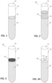
- FIG. 1 shows an uncapped sample tube for use with embodiments and with traditional automation systems.
- a sample fluid 10 is contained in a sample tube 12 having a top opening 13.
- the top surface 14 of the fluid sample is exposed in FIG. 1 , which makes sample 10 prone to splashing under sudden acceleration.
- Sample tube 12 is generally a glass or transparent plastic tube having a rounded, closed end at the bottom to hold the patient sample fluid, an open end at the top that is configured to receive a cap (e.g., a friction fit cap) and to accept a pipette when uncapped, and cylindrical walls that are substantially parallel between the two ends.
- a cap e.g., a friction fit cap
- tubes are moved throughout the laboratory environment via trays holding a large number of tubes (e.g., 55) that can be carried or accepted by an automation system or via carriers that hold a small number of tubes (generally one, but carriers can be configured to hold a handful of tubes) that are designed to traverse an automation system.
- trays holding a large number of tubes e.g., 55
- carriers that hold a small number of tubes generally one, but carriers can be configured to hold a handful of tubes
- FIG. 2 shows a configuration 20 whereby a foam 22 is applied to surface 14.
- Foam 22 can be applied via any conventional means, such as a pressurized foam or a two-part foam that is combined and dispensed via a nozzle tip that can be inserted into opening 13 of sample tube 12. Foam can be dispensed anywhere between opening 13 and surface 14. Because the density of foam 22 is less than that of sample fluid 10, the foam will form and float on top of the fluid. The density of the foam can be manipulated to control the density or size of air/gas bubbles to result in a density that allows the foam to float on surface 14.
- Exemplary materials for the foam can include any suitable foam known in the art that will not react with the patient sample, will not leave a residue on the pipette that will be inserted through the foam to access the patient sample, will not clog the pipette, and ideally the material is not electrolytic or conductive, which can prevent interference with the level sense mechanism on the pipette.
- the level sense of a pipette can be calibrated to account for unknown approximate thickness of foam 22, if foam 22 affects the level sense signal detected by the pipette (e.g., capacitive level sense voltage).
- Suitable foam materials may include, any inert, hydrophobic material that readily forms a matrix with gas to form a foam. This allows the foam to float without interfering with the operations of the pipette.
- FIG 3 shows a configuration 30 whereby a gel 32 is applied to surface 14.
- Gel 32 can be applied via any conventional means, such as a nozzle tip that can be inserted into opening 13 a sample tube 12 to dispense a viscous liquid gel. In some examples, this gel may set to some degree after dispensing, or remain in substantially the same viscous liquid state as it was when dispensed.
- the density of gel 32 should be less than that of sample fluid 10, allowing it to float on top of surface 14. Because the gel 32 is highly viscous and cohesive, it can provide a mechanical barrier to rapid changes in surface 14, such as would be common with sloshing, which could lead to spilling.
- gel 32 can be any suitable gel known in the art that will not react with the patient sample, will not leave a residue on the pipette that will be inserted through the foam to access the patient sample, will not clog the pipette, and ideally the material is not electrolytic or conductive, to prevent interference with the level sense mechanism on the pipette.
- the level sense of a pipette can be calibrated to account for unknown approximate thickness of gel 32, if gel 32 affects the level sense signal detected by the pipette (e.g., capacitive level sense voltage).
- a gel material that has some level of adhesion with the glass of sample tube 12, providing additional shear resistance to sloshing.
- Suitable foam materials may include any inert hydrophobic polymer material that is ideally nonconductive.
- the foam can be placed in a uniform thickness, such that the level sense mechanism can compensate for the thickness of the gel.
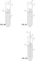
- FIGs. 4A through 4D shows configurations and in which a disk is used to mitigate sloshing and spillage, rather than (or in some embodiments, in addition to) foam or gel floating on top of the patient sample.
- Each of the disks shown in FIGs. 4A - 4D is a substantially flat disk configured to be placed within a patient sample tube and to float on the patient sample fluid (i.e., the average density of the disk is less than that of the fluid).
- Each disk has a center opening configured to accept a pipette and provide access to the patient sample fluid without exposing the entire surface of the patient sample fluid. Substantially more than half of the surface area of the sample is covered by the layer of material of the disk. For example, the radius of the opening is generally about half the radius of the disk or less. This allows access while covering most of the surface to provide substantial splash resistance. Moreover any gap between the disk and the tube walls is substantially less than the radius of the opening.
- FIGs. 4A - 4C show three different cross-section approaches to the disk.
- the disk is constructed of a material having sufficient average density such that the disk floats on the surface of the patient sample.
- the disk includes an orifice that allows a pipette to enter the sample fluid in the center of the disk.
- the diameter and shape of the orifice can vary depending on the tolerances of positioning the pipette with respect to the center of the patient sample tube.
- the orifice can be approximately 5 mm in diameter to allow a 1mm pipette to enter the patient sample if the center of the disk is within 2 mm of its expected location.
- the diameter of the orifice be substantially larger (e.g., approximately twice the diameter of the pipette or much larger) than the diameter of the pipette to allow for tolerance and positioning deviation.
- the exact size and shape of the orifice can be selected for the tolerances of each system in which the disk is used. For example, where the diameter of the patient sample tube varies, different size disks can be used for each type of sample tube, or a common sized disk can be used with a sufficiently large orifice to accommodate shifting of the disk relative to the walls of the patient sample tube.
- FIG. 5 shows an embodiment where the orifice of the disk is not entirely circular, including additional radial features that extend the length of the edge of the orifice, which may improve mitigation of rapid motion of the surface of the patient sample.
- the orifices in FIGs. 4A - 4D are circular, but it should be appreciated that different suitable shapes (e.g. symmetric shapes with a large central opening, such as star shapes, hexagons, octagons, or other polygons) could be used.
- suitable shapes e.g. symmetric shapes with a large central opening, such as star shapes, hexagons, octagons, or other polygons
- FIGs. 4A - 4D do not all have perfectly rectangular cross-sections, these can all be said to be substantially flat as the top or bottom surface only deviates from horizontal less than the thickness of the disk.
- the disks float atop the surface of the patient sample tube
- different cross-sectional profiles can be used to affect how the top of the disk floats relative to the surface of the patient sample. This may be needed where optical means are used to determine the fluid height in the patient sample tube, or where it is desired that the meniscus is low relative to the top surface of the disk or at or near the top surface of the disk.
- the available portion of a fluid sample surface 14 is limited to the size of orifice 36 (not drawn to scale) disk 34 floats atop fluid sample 10 due to the average density of disk 34. It is generally desirable to use a nonporous material for the disk.
- disk 34 is of uniform density, such as a low-density polyethylene or semi rigid closed cell foam material is sufficiently dense to allow it to float on the patient sample.
- disk 34 is a nonuniform density, such as a gas-filled, hollow material or a foam filled structure.
- a disk may be a hollow polypropylene structure filled with air or nitrogen to add buoyancy. This allows higher density materials to be used.
- Disk 34 is constructed so that fluid surface 14 is substantially at or near the top surface of disk 34. This can allow optical determination of the level of the patient sample in the tube by observing the location of the disk.
- FIG. 4B shows an alternative example of the disk 38 having a wedge-shaped profile that allows the top surface of disk 38 to be slightly concave, such that the top surface at the edge of orifice 40 is substantially at the same height, within a fraction of a millimeter, as the top surface of the sample 14. This can mitigate mechanical action of waves in surface 14 from impacting vertical surfaces of disk 38.
- disk 42 is of substantially uniform thickness, giving disk 42 a traditional washer shape. Because disk 42 is sufficiently dense that it floats on top of surface 14, the top surface of disk 42 can be substantially above surface 14, where the height differential is determined by the density of material used for disk 42, and therefore the displacement. This creates a vertical wall at the edge of orifice 44 with respect to surface 14 of the patient sample. Depending on the hygroscopic nature of the material used for disk 42, this sidewall can create a meniscus with surface 14, allowing additional adhesion of disk 42 to the patient sample to further mitigate sloshing.
- a pipette 46 is inserted into orifice 44, approximately at the center of the orifice 44.
- the exact location of pipette 46 with respect to orifice 44 depends on a shifting of disk 42 with respect to tube 12, such as when the diameter of the disk is substantially less than the inner diameter of tube 12, as well as any positioning error of the tube relative to the pipette.
- This differential can be due to manufacturing tolerances or designed intentionally to ensure that disk 42 fits with different tubes or different tolerances of tubes.
- the disk diameter is intentionally substantially the same as the inner diameter of the patient sample tube. This allows a mechanical interaction between the side of the disk and the tube to provide additional support in resisting splashing motion.
- any distance between disk 42 and tube 12 should be substantially smaller than the size of orifice 44.
- any distance between disk 42 and tube 12 should be substantially smaller than the size of orifice 44.
- FIG. 5 shows an embodiment where a disk has a non-circular orifice.
- Disk 50 includes an orifice 52 having a center opening comprising majority of the area of orifice 52 and radial channels 54 which are formed between tabs 56.
- the center portion of orifice 52 is substantially round (e.g. the tips of the tabs 56 are all approximately the same distance from the center of the disk).
- the tips of tabs 56 can be concave to create a fully round opening or can be substantially flat/straight creating a polygonal opening that is substantially round (e.g., an octagonal opening where eight tabs are used).
- the width of channels 54 can vary depending on the application.
- the width of channels 54 are substantially wide to form a meniscus with the fluid on which the disk floats.
- the overall length of edges making contact with the fluid can be increased and the openings between the channels 54 in the center portion of the orifice can act to break up any waves that begin to form in the orifice 52.
- FIG. 6 shows disk 50 placed in a tube in a top-down view.
- disk 50 floats atop sample fluid with some gap between the edge of the disk and the walls of sample tube 12. This allows the disk to move slightly during motion, allowing the disk to move along with the surface of the fluid.
- the gap between the disk and the tube wall is relatively small, allowing a pipette inserted into the center of tube 12 to always fall within orifice 52, allowing the pipette to interact with the fluid sample without interference by disk 50.
- the disk inserted into the patient sample tube is reusable, and is constructed in such a way that it is washable or autoclavable to fully sanitize the disk for reuse in future patient samples.
- the disk is intended to be disposable, being constructed of material suitable for mass production to bring the cost down. Suitable materials for construction of a disk, depending on intended use, can include polypropylene, polystyrene, other rigid polymers, or other materials that may be produced to have a low enough density to float on top the patient sample fluid.
- a two-part plastic shell is constructed sealing a gas within the disk, allowing a denser material to be used, but causing the overall density of the disk to be less than that of the patient sample fluid.
- a plurality of nonconductive floating balls may be placed into the patient sample tube. Because these balls are nonconductive, their presence should not interfere with the level sense mechanism of the pipette. Furthermore, because these balls float independently, they can easily move out of the way of the pipette as it is inserted, without substantially interfering with the aspiration process. These balls may be constructed of any of the materials described with respect to a disk.
- FIG. 7 shows an exemplary method 60 for using any of the materials that are placed atop the patient sample fluid.
- the patient sample tube is de-capped. This can be a manual operation or automatic operation using a mechanical decapper that may be accessible to an automation system in the laboratory environment or as a standalone station.
- a mechanical decapper that may be accessible to an automation system in the laboratory environment or as a standalone station.
- rapid movement of the sample tube can result in sloshing and splashing.
- a layer of material is placed atop the patient sample fluid, as explained above. Only step 66 is part of the present invention, with steps 64 or 65 just being examples not part of the present invention.
- a foam layer may be placed into the sample tube, causing a foam to float atop the patient sample fluid and provide a mechanical mechanism that restricts splashing-type movement (e.g., high-frequency or erratic motion on the surface of the patient sample fluid).
- Low-speed movement may be less restricted by the foam, as the foam can conform to the surface and changes in the shape of the tube walls with respect to that surface, such as when tilting the tube.
- the density and any a semi-rigidity of the foam can restrict rapid changes to the surface.
- a gel is placed into the sample tube, causing the gel to float atop the patient sample fluid and restrict splashing movements as described above.
- a disk having an orifice suitable for insertion of a pipette is placed into the sample tube, allowing the disk to float on top of the patient sample fluid. This disk restricts the splashing type movement of the patient sample, while allowing insertion of the pipette.
- the patient sample is prepared to move through the laboratory environment or automation system with less risk of spillage or splashing.
- the layer of material may be placed onto the patient sample fluid at steps 64 through 66 via a station in the automation system that uses a robot arm to assist in placing the foam, gel, or disk into the sample tube.
- the automation system transports the sample tube within the automation system to the next station, such as a clinical analyzer attached to the automation system.
- the layer of material may be used to mitigate splashing of samples in trays that are manually carried throughout the laboratory environment. In such a scenario, step 68 would be carried out manually by an operator of the laboratory equipment.
- a pipette is inserted into the patient sample fluid.
- this pipette is part of a robot arm or mechanical carriage that utilizes actuators to position the pipette substantially near the center (e.g. within 1 to 2 mm) of the vertical axis/center point of the patient sample tube. Then, the pipette is moved via the actuators vertically downward, such that the tip of the pipette is submerged in the patient sample before aspirating the patient sample. By centering and moving of the pipette downward, the pipette moves through the protective material layer on top of the patient sample fluid.
- the pipette moves through the foam or gel, such that the tip is submerged before aspirating a portion of the patient sample.
- foam and gel examples not part of the present invention, because aspiration does not occur until after the tip is submerged, gel and foam are generally not aspirated along with the fluid. This prevents the foam or gel from contaminating the sample aspirate.
- the disk includes a central orifice that is open where the pipette is inserted.
- the pipette moves through the protective material layer, without substantial interference from the material. This allows the material to prevent splashing, while also allowing normal aspiration of the patient sample.
- a portion of the patient sample fluid is aspirated by the pipette. This is accomplished by producing a negative pressure within the pipette, such as by using a pneumatic mechanism or piston to draw fluid into the pipette.
Landscapes
- Health & Medical Sciences (AREA)
- Chemical & Material Sciences (AREA)
- Clinical Laboratory Science (AREA)
- Chemical Kinetics & Catalysis (AREA)
- Analytical Chemistry (AREA)
- General Health & Medical Sciences (AREA)
- Hematology (AREA)
- Medicinal Chemistry (AREA)
- Life Sciences & Earth Sciences (AREA)
- Biochemistry (AREA)
- General Physics & Mathematics (AREA)
- Immunology (AREA)
- Pathology (AREA)
- Physics & Mathematics (AREA)
- Sampling And Sample Adjustment (AREA)
- Hydrology & Water Resources (AREA)
Claims (8)
- Procédé permettant d'atténuer le renversement d'un échantillon de patient (10) dans un système d'automatisation de laboratoire comprenant les étapes consistant à :désoperculer un tube d'échantillon de patient (12) comprenant un tube de verre avec une ouverture (13) et un échantillon de fluide de patient (10) contenu à l'intérieur ;placer un disque rond, sensiblement plat (34, 38, 42, 50) comprenant une ouverture centrale (36, 40, 44, 52) sur une surface supérieure (14) de l'échantillon de fluide de patient (10) pour limiter le mouvement d'éclaboussure de la surface supérieure (14) ;transporter l'échantillon de patient (10) vers une station à pipettes ;insérer une pipette (46) à travers l'ouverture (36, 40, 44, 52) ; etaspirer une partie de l'échantillon de fluide de patient (10) par l'intermédiaire de la pipette (46) ;dans lequelle disque plat (34, 38, 42, 50) est configuré pour être placé dans le tube d'échantillon de patient (12) et pour flotter sur l'échantillon de fluide de patient (10) et l'ouverture centrale (36, 40, 44, 52) est configurée pour permettre l'accès à l'échantillon de fluide de patient (10) sans exposer la surface entière (14) de l'échantillon de fluide de patient (10), caractérisé en ce que le disque (50) comprend des canaux radiaux (54) et des languettes (56) et que la partie centrale de l'ouverture centrale (52) est sensiblement ronde et que la largeur des canaux 54 est sensiblement large de manière à former un ménisque avec le fluide (10) sur lequel le disque (50) flotte.
- Appareil configuré pour atténuer le renversement de tubes d'échantillons de patients (12) comprenant :un tube d'échantillon de patient (12) comprenant un matériau cylindrique ayant une extrémité fermée configurée pour contenir un échantillon de fluide de patient (10) et une extrémité ouverte (13) configurée pour accepter une pipette ; etun disque rond, sensiblement plat (34, 38, 42, 50) configuré pour être placé dans le tube d'échantillon de patient (12) et capable de flotter sur un échantillon de fluide de patient (10) lorsqu'il est contenu dans le tube d'échantillon de patient (12), comprenant une ouverture centrale (36, 40, 44, 52) configurée pour permettre l'accès à l'échantillon de fluide de patient (10) sans exposer la totalité de la surface (14) de l'échantillon de fluide de patient (10), caractérisé en ce que le disque (34, 38, 42, 50) comprend des canaux radiaux (54) et des languettes (56) et que la partie centrale de l'ouverture centrale (52) est sensiblement ronde et que la largeur de canaux 54 est sensiblement large de manière à former un ménisque avec l'échantillon de fluide de patient (10) - lorsqu'il est contenu dans le tube d'échantillon de patient (12) - sur lequel le disque (50) peut flotter.
- Appareil de la revendication 2, dans lequel le disque (34, 38, 42, 50) est construit en polypropylène ou en polystyrène.
- Appareil de la revendication 2, dans lequel le disque (34, 38, 42, 50) comprend une structure creuse telle que la densité moyenne est inférieure à la densité de l'échantillon de fluide de patient (10).
- Appareil de la revendication 2, dans lequel l'ouverture centrale (36, 40, 44, 52) a un diamètre d'environ 5 mm.
- Appareil de la revendication 2, dans lequel le disque (34, 38, 42, 50) a une densité non uniforme et est construit à partir d'un matériau creux rempli de gaz.
- Appareil de la revendication 2, dans lequel le disque (34, 38, 42, 50) a une densité non uniforme et consiste en une structure remplie de mousse.
- Appareil de la revendication 2, dans lequel le disque (34, 38, 42, 50) est une structure creuse en polypropylène remplie d'air ou d'azote.
Applications Claiming Priority (2)
| Application Number | Priority Date | Filing Date | Title |
|---|---|---|---|
| US201562212452P | 2015-08-31 | 2015-08-31 | |
| PCT/US2016/048556 WO2017040171A1 (fr) | 2015-08-31 | 2016-08-25 | Procédé et dispositif destinés à la prévention d'éclaboussures d'un échantillon de fluide non recouvert pendant le transport sur un équipement de laboratoire de diagnostic |
Publications (3)
| Publication Number | Publication Date |
|---|---|
| EP3345005A1 EP3345005A1 (fr) | 2018-07-11 |
| EP3345005A4 EP3345005A4 (fr) | 2019-05-22 |
| EP3345005B1 true EP3345005B1 (fr) | 2023-11-15 |
Family
ID=58188000
Family Applications (1)
| Application Number | Title | Priority Date | Filing Date |
|---|---|---|---|
| EP16842629.4A Active EP3345005B1 (fr) | 2015-08-31 | 2016-08-25 | Procédé et dispositif destinés à la prévention d'éclaboussures d'un échantillon de fluide non recouvert pendant le transport sur un équipement de laboratoire de diagnostic |
Country Status (3)
| Country | Link |
|---|---|
| US (1) | US10576473B2 (fr) |
| EP (1) | EP3345005B1 (fr) |
| WO (1) | WO2017040171A1 (fr) |
Citations (2)
| Publication number | Priority date | Publication date | Assignee | Title |
|---|---|---|---|---|
| JP2000214171A (ja) * | 1999-01-20 | 2000-08-04 | Internatl Reagents Corp | 溶液安定化部材及び溶液の安定化方法 |
| JP2009058322A (ja) * | 2007-08-31 | 2009-03-19 | Hitachi High-Technologies Corp | 液体容器、及び自動分析装置 |
Family Cites Families (15)
| Publication number | Priority date | Publication date | Assignee | Title |
|---|---|---|---|---|
| US3982812A (en) * | 1973-10-01 | 1976-09-28 | General Electric Company | Power cable separable connector having gasket means for restricting the flow of arc-generated gases therefrom |
| US3972812A (en) * | 1975-05-08 | 1976-08-03 | Becton, Dickinson And Company | Blood serum separation filter disc |
| US4150089A (en) * | 1977-09-06 | 1979-04-17 | Linet Michael S | Multi-chamber test tube |
| JPH01111656A (ja) * | 1987-10-20 | 1989-04-28 | Fuji Photo Film Co Ltd | 標準液等の容器 |
| US5091304A (en) * | 1989-08-21 | 1992-02-25 | International Technidyne Corporation | Whole blood activated partial thromboplastin time test and associated apparatus |
| DK0515506T3 (da) * | 1990-02-16 | 2000-05-08 | Hoffmann La Roche | Fremgangsmåde til påvisning af carcinogene humane papillomavirus |
| JPH0774772B2 (ja) * | 1990-12-31 | 1995-08-09 | エイ. レビン ロバート | 血液サンプリング組立体、ターゲット細胞の採取方法およびターゲット成分の採取方法 |
| US5403388A (en) * | 1993-05-12 | 1995-04-04 | Pfiffner; Tim E. | Surfactant mediation sparge tube |
| CZ262097A3 (cs) * | 1995-02-16 | 1999-01-13 | Smithkline Beecham Corporation | Automatizovaný přístroj |
| US5632905A (en) * | 1995-08-07 | 1997-05-27 | Haynes; John L. | Method and apparatus for separating formed and unformed components |
| JP4020843B2 (ja) * | 2003-09-05 | 2007-12-12 | 株式会社日立ハイテクノロジーズ | 分析装置及び試薬容器 |
| MXPA06015104A (es) | 2004-06-17 | 2007-03-26 | Bard Inc C R | Tapa recolectora de tejido para un recipiente para muestras. |
| WO2006104076A1 (fr) * | 2005-03-28 | 2006-10-05 | Kurume University | Flotteur et récipient de liquide utilisant le flotteur, procédé d’évitement des dysfonctionnnements de sonde dans un analyseur automatique et prodédé d’inspection utilisant un analyseur automatique |
| CN201222009Y (zh) * | 2008-05-09 | 2009-04-15 | 华东理工大学 | 一种自动取样器 |
| US9381524B2 (en) * | 2011-11-08 | 2016-07-05 | Becton, Dickinson And Company | System and method for automated sample preparation |
-
2016
- 2016-08-25 EP EP16842629.4A patent/EP3345005B1/fr active Active
- 2016-08-25 WO PCT/US2016/048556 patent/WO2017040171A1/fr not_active Ceased
- 2016-08-25 US US15/751,382 patent/US10576473B2/en active Active
Patent Citations (2)
| Publication number | Priority date | Publication date | Assignee | Title |
|---|---|---|---|---|
| JP2000214171A (ja) * | 1999-01-20 | 2000-08-04 | Internatl Reagents Corp | 溶液安定化部材及び溶液の安定化方法 |
| JP2009058322A (ja) * | 2007-08-31 | 2009-03-19 | Hitachi High-Technologies Corp | 液体容器、及び自動分析装置 |
Also Published As
| Publication number | Publication date |
|---|---|
| EP3345005A1 (fr) | 2018-07-11 |
| US20180257071A1 (en) | 2018-09-13 |
| WO2017040171A1 (fr) | 2017-03-09 |
| US10576473B2 (en) | 2020-03-03 |
| EP3345005A4 (fr) | 2019-05-22 |
Similar Documents
| Publication | Publication Date | Title |
|---|---|---|
| US8187558B2 (en) | Containers for reducing or eliminating foaming | |
| CN108325439B (zh) | 减轻液体中的气泡形成的方法和设备 | |
| EP3885044A1 (fr) | Cartouche pour dosage a base de reactifs | |
| US9562921B2 (en) | Immunodiagnostic test element having weakened foil layer | |
| EP3859344B1 (fr) | Cuve à réaction d'analyseur automatisé | |
| JP7042728B2 (ja) | ピペット装置およびピペット装置位置決めシステム | |
| US20250144635A1 (en) | Evaporation-limiting inserts for reagent containers and related methods of use | |
| EP3345005B1 (fr) | Procédé et dispositif destinés à la prévention d'éclaboussures d'un échantillon de fluide non recouvert pendant le transport sur un équipement de laboratoire de diagnostic | |
| CA2806380C (fr) | Fermeture a bande de cloison | |
| EP3842768B1 (fr) | Dispositif de détection de niveau de liquide | |
| WO2025105076A1 (fr) | Appareil et procédé de détection de surface de liquide pour détection de surface de liquide | |
| JP7595157B2 (ja) | 検体容器及び自動分析装置 | |
| JP2010185829A (ja) | 分注機構、分注方法及び分析装置 | |
| CN112934286A (zh) | 一种毛细管移液装置 | |
| CN115702354A (zh) | 用于样品容器中的流体液位的差分测量的系统和方法 | |
| HK1243670B (en) | Multi-well tray for performing automated reagent-based assays |
Legal Events
| Date | Code | Title | Description |
|---|---|---|---|
| STAA | Information on the status of an ep patent application or granted ep patent |
Free format text: STATUS: THE INTERNATIONAL PUBLICATION HAS BEEN MADE |
|
| PUAI | Public reference made under article 153(3) epc to a published international application that has entered the european phase |
Free format text: ORIGINAL CODE: 0009012 |
|
| STAA | Information on the status of an ep patent application or granted ep patent |
Free format text: STATUS: REQUEST FOR EXAMINATION WAS MADE |
|
| 17P | Request for examination filed |
Effective date: 20180326 |
|
| AK | Designated contracting states |
Kind code of ref document: A1 Designated state(s): AL AT BE BG CH CY CZ DE DK EE ES FI FR GB GR HR HU IE IS IT LI LT LU LV MC MK MT NL NO PL PT RO RS SE SI SK SM TR |
|
| AX | Request for extension of the european patent |
Extension state: BA ME |
|
| DAV | Request for validation of the european patent (deleted) | ||
| DAX | Request for extension of the european patent (deleted) | ||
| A4 | Supplementary search report drawn up and despatched |
Effective date: 20190418 |
|
| RIC1 | Information provided on ipc code assigned before grant |
Ipc: G01N 35/04 20060101AFI20190412BHEP Ipc: G01N 1/10 20060101ALI20190412BHEP |
|
| STAA | Information on the status of an ep patent application or granted ep patent |
Free format text: STATUS: EXAMINATION IS IN PROGRESS |
|
| 17Q | First examination report despatched |
Effective date: 20210910 |
|
| GRAP | Despatch of communication of intention to grant a patent |
Free format text: ORIGINAL CODE: EPIDOSNIGR1 |
|
| STAA | Information on the status of an ep patent application or granted ep patent |
Free format text: STATUS: GRANT OF PATENT IS INTENDED |
|
| INTG | Intention to grant announced |
Effective date: 20230605 |
|
| GRAS | Grant fee paid |
Free format text: ORIGINAL CODE: EPIDOSNIGR3 |
|
| GRAA | (expected) grant |
Free format text: ORIGINAL CODE: 0009210 |
|
| STAA | Information on the status of an ep patent application or granted ep patent |
Free format text: STATUS: THE PATENT HAS BEEN GRANTED |
|
| AK | Designated contracting states |
Kind code of ref document: B1 Designated state(s): AL AT BE BG CH CY CZ DE DK EE ES FI FR GB GR HR HU IE IS IT LI LT LU LV MC MK MT NL NO PL PT RO RS SE SI SK SM TR |
|
| REG | Reference to a national code |
Ref country code: CH Ref legal event code: EP Ref country code: GB Ref legal event code: FG4D |
|
| REG | Reference to a national code |
Ref country code: DE Ref legal event code: R096 Ref document number: 602016084181 Country of ref document: DE |
|
| REG | Reference to a national code |
Ref country code: IE Ref legal event code: FG4D |
|
| REG | Reference to a national code |
Ref country code: LT Ref legal event code: MG9D |
|
| REG | Reference to a national code |
Ref country code: NL Ref legal event code: MP Effective date: 20231115 |
|
| PG25 | Lapsed in a contracting state [announced via postgrant information from national office to epo] |
Ref country code: GR Free format text: LAPSE BECAUSE OF FAILURE TO SUBMIT A TRANSLATION OF THE DESCRIPTION OR TO PAY THE FEE WITHIN THE PRESCRIBED TIME-LIMIT Effective date: 20240216 |
|
| PG25 | Lapsed in a contracting state [announced via postgrant information from national office to epo] |
Ref country code: IS Free format text: LAPSE BECAUSE OF FAILURE TO SUBMIT A TRANSLATION OF THE DESCRIPTION OR TO PAY THE FEE WITHIN THE PRESCRIBED TIME-LIMIT Effective date: 20240315 |
|
| PG25 | Lapsed in a contracting state [announced via postgrant information from national office to epo] |
Ref country code: LT Free format text: LAPSE BECAUSE OF FAILURE TO SUBMIT A TRANSLATION OF THE DESCRIPTION OR TO PAY THE FEE WITHIN THE PRESCRIBED TIME-LIMIT Effective date: 20231115 |
|
| REG | Reference to a national code |
Ref country code: AT Ref legal event code: MK05 Ref document number: 1632232 Country of ref document: AT Kind code of ref document: T Effective date: 20231115 |
|
| PG25 | Lapsed in a contracting state [announced via postgrant information from national office to epo] |
Ref country code: NL Free format text: LAPSE BECAUSE OF FAILURE TO SUBMIT A TRANSLATION OF THE DESCRIPTION OR TO PAY THE FEE WITHIN THE PRESCRIBED TIME-LIMIT Effective date: 20231115 |
|
| PG25 | Lapsed in a contracting state [announced via postgrant information from national office to epo] |
Ref country code: AT Free format text: LAPSE BECAUSE OF FAILURE TO SUBMIT A TRANSLATION OF THE DESCRIPTION OR TO PAY THE FEE WITHIN THE PRESCRIBED TIME-LIMIT Effective date: 20231115 |
|
| PG25 | Lapsed in a contracting state [announced via postgrant information from national office to epo] |
Ref country code: ES Free format text: LAPSE BECAUSE OF FAILURE TO SUBMIT A TRANSLATION OF THE DESCRIPTION OR TO PAY THE FEE WITHIN THE PRESCRIBED TIME-LIMIT Effective date: 20231115 |
|
| PG25 | Lapsed in a contracting state [announced via postgrant information from national office to epo] |
Ref country code: NL Free format text: LAPSE BECAUSE OF FAILURE TO SUBMIT A TRANSLATION OF THE DESCRIPTION OR TO PAY THE FEE WITHIN THE PRESCRIBED TIME-LIMIT Effective date: 20231115 Ref country code: LT Free format text: LAPSE BECAUSE OF FAILURE TO SUBMIT A TRANSLATION OF THE DESCRIPTION OR TO PAY THE FEE WITHIN THE PRESCRIBED TIME-LIMIT Effective date: 20231115 Ref country code: IS Free format text: LAPSE BECAUSE OF FAILURE TO SUBMIT A TRANSLATION OF THE DESCRIPTION OR TO PAY THE FEE WITHIN THE PRESCRIBED TIME-LIMIT Effective date: 20240315 Ref country code: GR Free format text: LAPSE BECAUSE OF FAILURE TO SUBMIT A TRANSLATION OF THE DESCRIPTION OR TO PAY THE FEE WITHIN THE PRESCRIBED TIME-LIMIT Effective date: 20240216 Ref country code: ES Free format text: LAPSE BECAUSE OF FAILURE TO SUBMIT A TRANSLATION OF THE DESCRIPTION OR TO PAY THE FEE WITHIN THE PRESCRIBED TIME-LIMIT Effective date: 20231115 Ref country code: BG Free format text: LAPSE BECAUSE OF FAILURE TO SUBMIT A TRANSLATION OF THE DESCRIPTION OR TO PAY THE FEE WITHIN THE PRESCRIBED TIME-LIMIT Effective date: 20240215 Ref country code: AT Free format text: LAPSE BECAUSE OF FAILURE TO SUBMIT A TRANSLATION OF THE DESCRIPTION OR TO PAY THE FEE WITHIN THE PRESCRIBED TIME-LIMIT Effective date: 20231115 Ref country code: PT Free format text: LAPSE BECAUSE OF FAILURE TO SUBMIT A TRANSLATION OF THE DESCRIPTION OR TO PAY THE FEE WITHIN THE PRESCRIBED TIME-LIMIT Effective date: 20240315 |
|
| PG25 | Lapsed in a contracting state [announced via postgrant information from national office to epo] |
Ref country code: SE Free format text: LAPSE BECAUSE OF FAILURE TO SUBMIT A TRANSLATION OF THE DESCRIPTION OR TO PAY THE FEE WITHIN THE PRESCRIBED TIME-LIMIT Effective date: 20231115 Ref country code: RS Free format text: LAPSE BECAUSE OF FAILURE TO SUBMIT A TRANSLATION OF THE DESCRIPTION OR TO PAY THE FEE WITHIN THE PRESCRIBED TIME-LIMIT Effective date: 20231115 Ref country code: PL Free format text: LAPSE BECAUSE OF FAILURE TO SUBMIT A TRANSLATION OF THE DESCRIPTION OR TO PAY THE FEE WITHIN THE PRESCRIBED TIME-LIMIT Effective date: 20231115 Ref country code: NO Free format text: LAPSE BECAUSE OF FAILURE TO SUBMIT A TRANSLATION OF THE DESCRIPTION OR TO PAY THE FEE WITHIN THE PRESCRIBED TIME-LIMIT Effective date: 20240215 Ref country code: LV Free format text: LAPSE BECAUSE OF FAILURE TO SUBMIT A TRANSLATION OF THE DESCRIPTION OR TO PAY THE FEE WITHIN THE PRESCRIBED TIME-LIMIT Effective date: 20231115 Ref country code: HR Free format text: LAPSE BECAUSE OF FAILURE TO SUBMIT A TRANSLATION OF THE DESCRIPTION OR TO PAY THE FEE WITHIN THE PRESCRIBED TIME-LIMIT Effective date: 20231115 |
|
| PG25 | Lapsed in a contracting state [announced via postgrant information from national office to epo] |
Ref country code: DK Free format text: LAPSE BECAUSE OF FAILURE TO SUBMIT A TRANSLATION OF THE DESCRIPTION OR TO PAY THE FEE WITHIN THE PRESCRIBED TIME-LIMIT Effective date: 20231115 |
|
| PG25 | Lapsed in a contracting state [announced via postgrant information from national office to epo] |
Ref country code: CZ Free format text: LAPSE BECAUSE OF FAILURE TO SUBMIT A TRANSLATION OF THE DESCRIPTION OR TO PAY THE FEE WITHIN THE PRESCRIBED TIME-LIMIT Effective date: 20231115 |
|
| PG25 | Lapsed in a contracting state [announced via postgrant information from national office to epo] |
Ref country code: SK Free format text: LAPSE BECAUSE OF FAILURE TO SUBMIT A TRANSLATION OF THE DESCRIPTION OR TO PAY THE FEE WITHIN THE PRESCRIBED TIME-LIMIT Effective date: 20231115 |
|
| PG25 | Lapsed in a contracting state [announced via postgrant information from national office to epo] |
Ref country code: SM Free format text: LAPSE BECAUSE OF FAILURE TO SUBMIT A TRANSLATION OF THE DESCRIPTION OR TO PAY THE FEE WITHIN THE PRESCRIBED TIME-LIMIT Effective date: 20231115 Ref country code: SK Free format text: LAPSE BECAUSE OF FAILURE TO SUBMIT A TRANSLATION OF THE DESCRIPTION OR TO PAY THE FEE WITHIN THE PRESCRIBED TIME-LIMIT Effective date: 20231115 Ref country code: RO Free format text: LAPSE BECAUSE OF FAILURE TO SUBMIT A TRANSLATION OF THE DESCRIPTION OR TO PAY THE FEE WITHIN THE PRESCRIBED TIME-LIMIT Effective date: 20231115 Ref country code: IT Free format text: LAPSE BECAUSE OF FAILURE TO SUBMIT A TRANSLATION OF THE DESCRIPTION OR TO PAY THE FEE WITHIN THE PRESCRIBED TIME-LIMIT Effective date: 20231115 Ref country code: EE Free format text: LAPSE BECAUSE OF FAILURE TO SUBMIT A TRANSLATION OF THE DESCRIPTION OR TO PAY THE FEE WITHIN THE PRESCRIBED TIME-LIMIT Effective date: 20231115 Ref country code: DK Free format text: LAPSE BECAUSE OF FAILURE TO SUBMIT A TRANSLATION OF THE DESCRIPTION OR TO PAY THE FEE WITHIN THE PRESCRIBED TIME-LIMIT Effective date: 20231115 Ref country code: CZ Free format text: LAPSE BECAUSE OF FAILURE TO SUBMIT A TRANSLATION OF THE DESCRIPTION OR TO PAY THE FEE WITHIN THE PRESCRIBED TIME-LIMIT Effective date: 20231115 |
|
| REG | Reference to a national code |
Ref country code: DE Ref legal event code: R097 Ref document number: 602016084181 Country of ref document: DE |
|
| PLBE | No opposition filed within time limit |
Free format text: ORIGINAL CODE: 0009261 |
|
| STAA | Information on the status of an ep patent application or granted ep patent |
Free format text: STATUS: NO OPPOSITION FILED WITHIN TIME LIMIT |
|
| 26N | No opposition filed |
Effective date: 20240819 |
|
| PG25 | Lapsed in a contracting state [announced via postgrant information from national office to epo] |
Ref country code: SI Free format text: LAPSE BECAUSE OF FAILURE TO SUBMIT A TRANSLATION OF THE DESCRIPTION OR TO PAY THE FEE WITHIN THE PRESCRIBED TIME-LIMIT Effective date: 20231115 |
|
| PG25 | Lapsed in a contracting state [announced via postgrant information from national office to epo] |
Ref country code: SI Free format text: LAPSE BECAUSE OF FAILURE TO SUBMIT A TRANSLATION OF THE DESCRIPTION OR TO PAY THE FEE WITHIN THE PRESCRIBED TIME-LIMIT Effective date: 20231115 |
|
| REG | Reference to a national code |
Ref country code: CH Ref legal event code: PL |
|
| PG25 | Lapsed in a contracting state [announced via postgrant information from national office to epo] |
Ref country code: LU Free format text: LAPSE BECAUSE OF NON-PAYMENT OF DUE FEES Effective date: 20240825 |
|
| PG25 | Lapsed in a contracting state [announced via postgrant information from national office to epo] |
Ref country code: CH Free format text: LAPSE BECAUSE OF NON-PAYMENT OF DUE FEES Effective date: 20240831 Ref country code: MC Free format text: LAPSE BECAUSE OF FAILURE TO SUBMIT A TRANSLATION OF THE DESCRIPTION OR TO PAY THE FEE WITHIN THE PRESCRIBED TIME-LIMIT Effective date: 20231115 |
|
| REG | Reference to a national code |
Ref country code: BE Ref legal event code: MM Effective date: 20240831 |
|
| PG25 | Lapsed in a contracting state [announced via postgrant information from national office to epo] |
Ref country code: BE Free format text: LAPSE BECAUSE OF NON-PAYMENT OF DUE FEES Effective date: 20240831 |
|
| PG25 | Lapsed in a contracting state [announced via postgrant information from national office to epo] |
Ref country code: IE Free format text: LAPSE BECAUSE OF NON-PAYMENT OF DUE FEES Effective date: 20240825 |
|
| REG | Reference to a national code |
Ref country code: DE Ref legal event code: R082 Ref document number: 602016084181 Country of ref document: DE |
|
| PG25 | Lapsed in a contracting state [announced via postgrant information from national office to epo] |
Ref country code: FI Free format text: LAPSE BECAUSE OF FAILURE TO SUBMIT A TRANSLATION OF THE DESCRIPTION OR TO PAY THE FEE WITHIN THE PRESCRIBED TIME-LIMIT Effective date: 20231115 |
|
| PGFP | Annual fee paid to national office [announced via postgrant information from national office to epo] |
Ref country code: GB Payment date: 20250902 Year of fee payment: 10 |
|
| PGFP | Annual fee paid to national office [announced via postgrant information from national office to epo] |
Ref country code: FR Payment date: 20250827 Year of fee payment: 10 |
|
| PGFP | Annual fee paid to national office [announced via postgrant information from national office to epo] |
Ref country code: DE Payment date: 20251020 Year of fee payment: 10 |
|
| PG25 | Lapsed in a contracting state [announced via postgrant information from national office to epo] |
Ref country code: CY Free format text: LAPSE BECAUSE OF FAILURE TO SUBMIT A TRANSLATION OF THE DESCRIPTION OR TO PAY THE FEE WITHIN THE PRESCRIBED TIME-LIMIT; INVALID AB INITIO Effective date: 20160825 |
|
| PG25 | Lapsed in a contracting state [announced via postgrant information from national office to epo] |
Ref country code: HU Free format text: LAPSE BECAUSE OF FAILURE TO SUBMIT A TRANSLATION OF THE DESCRIPTION OR TO PAY THE FEE WITHIN THE PRESCRIBED TIME-LIMIT; INVALID AB INITIO Effective date: 20160825 |