EP3345073B1 - Ortung von vorrichtungen in einer erweiterten realitätsumgebung - Google Patents
Ortung von vorrichtungen in einer erweiterten realitätsumgebung Download PDFInfo
- Publication number
- EP3345073B1 EP3345073B1 EP16751426.4A EP16751426A EP3345073B1 EP 3345073 B1 EP3345073 B1 EP 3345073B1 EP 16751426 A EP16751426 A EP 16751426A EP 3345073 B1 EP3345073 B1 EP 3345073B1
- Authority
- EP
- European Patent Office
- Prior art keywords
- augmented reality
- environment
- physical manifestation
- location
- image
- Prior art date
- Legal status (The legal status is an assumption and is not a legal conclusion. Google has not performed a legal analysis and makes no representation as to the accuracy of the status listed.)
- Active
Links
Images


Classifications
-
- G—PHYSICS
- G06—COMPUTING OR CALCULATING; COUNTING
- G06T—IMAGE DATA PROCESSING OR GENERATION, IN GENERAL
- G06T19/00—Manipulating three-dimensional [3D] models or images for computer graphics
- G06T19/006—Mixed reality
-
- G—PHYSICS
- G02—OPTICS
- G02B—OPTICAL ELEMENTS, SYSTEMS OR APPARATUS
- G02B27/00—Optical systems or apparatus not provided for by any of the groups G02B1/00 - G02B26/00, G02B30/00
- G02B27/01—Head-up displays
- G02B27/017—Head mounted
-
- G—PHYSICS
- G02—OPTICS
- G02B—OPTICAL ELEMENTS, SYSTEMS OR APPARATUS
- G02B27/00—Optical systems or apparatus not provided for by any of the groups G02B1/00 - G02B26/00, G02B30/00
- G02B27/01—Head-up displays
- G02B27/017—Head mounted
- G02B27/0172—Head mounted characterised by optical features
-
- G—PHYSICS
- G06—COMPUTING OR CALCULATING; COUNTING
- G06F—ELECTRIC DIGITAL DATA PROCESSING
- G06F3/00—Input arrangements for transferring data to be processed into a form capable of being handled by the computer; Output arrangements for transferring data from processing unit to output unit, e.g. interface arrangements
- G06F3/01—Input arrangements or combined input and output arrangements for interaction between user and computer
- G06F3/011—Arrangements for interaction with the human body, e.g. for user immersion in virtual reality
-
- G—PHYSICS
- G06—COMPUTING OR CALCULATING; COUNTING
- G06T—IMAGE DATA PROCESSING OR GENERATION, IN GENERAL
- G06T7/00—Image analysis
- G06T7/70—Determining position or orientation of objects or cameras
-
- H—ELECTRICITY
- H04—ELECTRIC COMMUNICATION TECHNIQUE
- H04R—LOUDSPEAKERS, MICROPHONES, GRAMOPHONE PICK-UPS OR LIKE ACOUSTIC ELECTROMECHANICAL TRANSDUCERS; ELECTRIC HEARING AIDS; PUBLIC ADDRESS SYSTEMS
- H04R29/00—Monitoring arrangements; Testing arrangements
- H04R29/004—Monitoring arrangements; Testing arrangements for microphones
- H04R29/005—Microphone arrays
-
- G—PHYSICS
- G02—OPTICS
- G02B—OPTICAL ELEMENTS, SYSTEMS OR APPARATUS
- G02B27/00—Optical systems or apparatus not provided for by any of the groups G02B1/00 - G02B26/00, G02B30/00
- G02B27/01—Head-up displays
- G02B27/0101—Head-up displays characterised by optical features
- G02B2027/0138—Head-up displays characterised by optical features comprising image capture systems, e.g. camera
-
- G—PHYSICS
- G02—OPTICS
- G02B—OPTICAL ELEMENTS, SYSTEMS OR APPARATUS
- G02B27/00—Optical systems or apparatus not provided for by any of the groups G02B1/00 - G02B26/00, G02B30/00
- G02B27/01—Head-up displays
- G02B27/0101—Head-up displays characterised by optical features
- G02B2027/014—Head-up displays characterised by optical features comprising information/image processing systems
-
- G—PHYSICS
- G02—OPTICS
- G02B—OPTICAL ELEMENTS, SYSTEMS OR APPARATUS
- G02B27/00—Optical systems or apparatus not provided for by any of the groups G02B1/00 - G02B26/00, G02B30/00
- G02B27/01—Head-up displays
- G02B27/0179—Display position adjusting means not related to the information to be displayed
- G02B2027/0187—Display position adjusting means not related to the information to be displayed slaved to motion of at least a part of the body of the user, e.g. head, eye
-
- G—PHYSICS
- G06—COMPUTING OR CALCULATING; COUNTING
- G06T—IMAGE DATA PROCESSING OR GENERATION, IN GENERAL
- G06T2215/00—Indexing scheme for image rendering
- G06T2215/16—Using real world measurements to influence rendering
Definitions
- Electronic devices may communicate with one another in various manners and for various purposes. For example, one device may identify and pair with one or more other devices by establishing a connection with each of the other devices. Once paired, the devices may perform any of a number of functions, such as one device controlling another and/or exchanging data between devices.
- an augmented reality method includes accessing first location information regarding a location of a user interaction device in a physical world, wherein the user interaction device is configured to generate an augmented reality representation with respect to the physical world, using the first location information, generating second location information which has increased accuracy regarding the location of the user interaction device in the physical world, and communicating augmented data to the user interaction device, and wherein the augmented data comprises the augmented reality representation.
- US 2014/118631 A1 discloses a head mounded display that outputs an audio signal of an external digital device according to whether the audio signal is directional output signal.
- US 2011/065496 A1 discloses a wagering game system and its operations are described herein.
- the operations can include detecting, at a gaming machine, a fiducial marker in one or more images captured by an image capture device of the gaming machine, determining an orientation of the fiducial marker, and detecting a fiducial code embedded within the fiducial marker.
- the operations can also include providing, via a network, fiducial code information and fiducial marker orientation information to a wagering game server to identify an augmented reality object associated with the fiducial code and determine attributes of the augmented reality object.
- the operations can further include receiving, at the gaming machine, wagering game content and the augmented reality object from the wagering game server, incorporating the augmented reality object within the wagering game content, and presenting the wagering game content comprising the augmented reality object on a display device of the gaming machine.
- WO 2015/064846 A1 discloses a marker through a camera unit; displaying a first augmented reality image of a shape of a 3D object on the basis of the detected first marker before the 3D object is output by the 3D printer; detecting the 3D object, which is output from the 3D printer, as a second marker if the 3D printer starts to output the 3D object; updating the first augmented reality image to a second augmented reality image on the basis of the first marker and the second marker; and displaying the second augmented reality image.
- Examples are disclosed herein that relate to identifying and localizing devices in an environment via an augmented reality display device.
- Examples are disclosed herein that relate to automatic identification and localization of devices in an environment via physically detectable outputs corresponding to locations of the devices.
- devices in the environment may output physical manifestations, e.g. lights, movements, sounds, etc. that are detectable by an augmented reality display device, for example by using on-board sensors.
- the augmented reality display device may instruct each device to modulate a physical manifestation of the device, and then detect the modulation of the physical manifestation. In this manner, the augmented reality display device may determine a device location for each detected device within the environment. Localization of the devices in the environment may help an augmented reality experience to be tailored to the device locations.
- an augmented reality display device may modify an image being displayed to avoid occluding the physical manifestation in the environment.
- Other adaptations of an augmented reality experience also may be made.
- a user interface for a controllable external device in the environment may be displayed in proximity to the physical manifestation of the device, and/or sounds output by the augmented reality display device may be adapted to sound as if originating from an external device that has been localized.
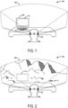
- FIG. 1 shows an example use scenario in which a user 100 is wearing an augmented reality display device 102.
- the augmented reality display device is configured to mix virtual imagery displayed within an augmented reality field of view 106 with a see-through view of a real-world environment 104.
- the augmented reality display device 102 includes a see-through display system that allows the presentation of augmented reality imagery via the display of virtual objects superimposed over the real-world environment 104.
- the augmented reality display device 102 includes one or more outward-facing image sensors configured to acquire image data of the real-world environment 104.
- image sensors include, but are not limited to, depth sensor systems (e.g. time-of-flight and/or structured light camera(s), as well as stereo camera systems), visible light image sensors, and infrared image sensors.
- the augmented reality display device 102 further may be configured to establish a coordinate frame for the real-world environment 104 via the acquired image data.
- the coordinate frame may be established from a three-dimensional mesh of the real-world environment 104 constructed from depth data acquired via an on-board depth sensor (e.g. by using a simultaneous localization and mapping method).
- the augmented reality display device may obtain previously acquired and stored depth data of the real-world environment 104, stored either locally or remotely.
- the real-world environment 104 includes a device 108 in the form of a computing system having a display screen 110.
- the augmented reality display device 102 may be configured to localize the display screen 110 by communicating with the device 108. Once localized, the augmented reality display device 102 may adjust displayed augmented reality imagery to avoid occlusion of the display screen 110.
- the augmented reality display device 102 may utilize image data analysis to localize the display screen 110 and/or other objects of interest in a coordinate frame of the augmented reality display device 102.
- the augmented reality display device 102 may discover the presence, identity and/or location of the device 108 via acquired sensor data (e.g. image data, audio data, etc.) in order to communicate with the device 108.
- the augmented reality display device 102 may detect the device 108 via a wireless network, such as via a WIFI or BLUETOOTH network (e.g. by a beaconing signal emitted by the device 108, or a response to a beaconing signal emitted by the augmented reality display device 102).
- the augmented reality display device 102 communicates with the device 108 and instruct the device 108 to alter a physical manifestation in a way that is detectable by a location-sensitive input device of the augmented reality display device 102.
- Examples of physical manifestations of the device 108 that can be controlled to localize the device in an environment include, but are not limited to, a display output (e.g. turn the display on or off, display a specified color, display a specified image, etc.) and an audio output (e.g. display a specified tone detectable via a directional microphone array).
- the augmented reality display device 102 assigns and stores a device location for the device 108 within the coordinate frame established by the augmented reality display device 102 for the real-world environment 104.
- the device location may be stored as an area in the coordinate frame occupied by the display screen 110 (e.g. as defined by the four corners of or perimeter of the display screen 110), or the overall device 108 (e.g. as defined by a perimeter of the device 108).
- the device location further may comprise information regarding which side or sides of the manifestation are not to be occluded.
- the stored device location may then be taken into account when presenting augmented reality effects, such as avoiding visual occlusion of a real world object.
- the augmented reality display device 102 may use the stored device location of the device 108 to display user interface elements that correspond to the stored device location, such as by positioning a virtual notification located above or nearby the device 108. Also, the augmented reality display device 102 may allow the user 100 to interact with displayed virtual icons representing files stored on the augmented reality display device 102, such as to drag-and-drop files (e.g. by moving virtual icons to a location over the real-world device) for transfer to the device 108 over the local area network.
- drag-and-drop files e.g. by moving virtual icons to a location over the real-world device
- Assigning the device 108 a location within the coordinate frame of the real-world environment 104 further allows the relative position of the device 108 and the augmented reality display device 102 to be tracked as a wearer of the augmented reality display device 102 moves about in the real-world environment 104.
- This allows the augmented reality display device 102 to modify its output based on a change in relative position between the augmented reality display device 102 and the physical manifestation of the device 108, for example, to move and/or modify a shape of a cutout region of a displayed virtual image to avoid occluding the physical manifestation and/or other objects.
- FIG. 2 shows the augmented reality display device 102 displaying virtual content (e.g. virtual terrain) superimposed over the real-world environment 104 within an augmented reality field of view 206, while avoiding occlusion of the display screen 110 such that any image being displayed on the display screen 110 may still be seen by the user 100.
- virtual content e.g. virtual terrain
- the augmented reality display device 102 may render an augmented reality image and remove a portion of the augmented reality image that corresponds to the size, shape and location of the display screen 110 from the perspective of the wearer of the augmented reality display device 102.
- the augmented reality display device 102 may capture the appearance of the display screen 110 and re-render the display screen 110 as part of the augmented reality image.
- the user 100 may still view the display output of the device 108 in the environment 104 while also viewing virtual content displayed by the augmented reality display device 102.
- Various sensors on the augmented reality display device 102 such as image sensors and/or inertial motion sensors, may be used to track motion of the augmented reality display device 102 in the use environment, and as such may be used to update the augmented reality image based upon the tracking to continually avoid occluding the display screen 110.
- the augmented reality display device 102 may identify and localize any other suitable devices in the environment. Examples include but are not limited to mobile devices, display devices, speakers, smart lights, printers, environmental systems (e.g. HVAC system components), and other controllable computing devices.
- the augmented reality display device 102 further may include any other suitable location-sensitive input devices than image sensors, such as a directional microphone array or other location-sensitive acoustic input sensor.
- an augmented reality display device may take any other suitable form than a head-mounted display device with a see-through display.
- an augmented reality display device may be implemented as a virtual reality head-mounted display with an opaque screen and an outward-facing camera configured to display video from the outward-facing camera composited with virtual imagery.
- an augmented reality display device may take the form of a non-wearable mobile display device configured to display virtual content via a viewfinder mode, or a wearable display device other than a head-mounted display device.
- FIG. 3 shows a block diagram illustrating an example augmented reality display system environment 300 including an example augmented reality display device 301 and a plurality of devices in the environment connected via a network 320.
- the augmented reality display device 301 includes a see-through display device 302, and one or more location-sensitive input devices 304. Examples of location-sensitive input devices 304 include, but are not limited to, one or more image sensor(s) 306 and/or a microphone array 308.
- the augmented reality display device 301 further includes a motion sensor 310, such as an inertial measurement unit having one or more accelerometers and/or one or more gyroscopic sensors.
- the augmented reality display device 301 may connect to one or more devices, illustrated as device 1 312 through device N 314.
- the illustrated devices 312, 314 may represent any suitable type of device.
- one or more of devices 312, 314 may comprise a desktop computer, laptop computer, smart phone, tablet or other portable device, smart appliance, peripheral device, smart device hub (e.g. a controller configured to control plural smart devices, such as lights, environmental systems, alarms, etc. in the environment), and the like.
- Each of the devices may include one or more controllable physical manifestations, as illustrated at physical manifestation 1 316 through physical manifestation N 318 for device 1. Any suitable controllable and detectable physical manifestation may be used to localize a device. Examples include, but are not limited to, light outputs (e.g.
- the network 320 may represent any suitable communication network, including but not limited to a computer network (local area and/or wide area, wired, wireless, etc.), mobile phone network, and/or other suitable communications network.
- the augmented reality display device 301 may also connect to the devices via direct connections, e.g. via BLUETOOTH.
- the augmented reality display device 301 may be configured to communicate with the devices via a controller 322, such as a smart device hub or other computing device, in the environment 300.
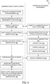
- FIG. 4 shows a flow diagram depicting an example method 400 for identifying and localizing devices in an environment via an augmented reality display device.
- the augmented reality display device establishes a coordinate frame for the environment, such as via depth data obtained from imaging the environment and/or from locally or remotely stored depth data.
- the augmented reality display device further may discover a presence of a device in the environment over a network, at 404.
- Some devices may provide a beaconing signal for discovery (e.g. a smart device or smart device hub), or may respond to a beaconing signal provided by the augmented reality display device.
- the augmented reality display device and the device in the environment may connect to each other.
- the augmented reality display device instructs the device in the environment to alter a physical manifestation, at 408.
- the physical manifestation may be integrated into the device itself (e.g. a display screen of a computing device), or may take the form of an output physically separate from but controlled by the device (e.g. a smart lamp controlled by a smart device hub controller).
- the augmented reality display device may directly communicate with the device in the environment to instruct the device to alter the physical manifestation.
- the augmented reality display device may communicate with the device in the environment via another external device, such as a controller that controls the device.
- the device in the environment alters the physical manifestation.
- the device may perform this process in any suitable way that is detectable by a location sensitive input device of the augmented reality display device.
- the physical manifestation may take the form of light controlled by the device in the environment, at 414, that is detectable by an image sensor of the augmented reality display device.
- a physical manifestation may take the form of content displayed on a display of a device in the environment.
- the display may be separate from the device itself (e.g. a projector or monitor physically separate from the device providing outputs), while in other examples the display may be integrated with the device.
- the physical manifestation may be the blinking of one or more lights emitted by a smart light, such as a lamp or overhead light in the environment.
- the physical manifestation may take the form of audio signals controlled by the device, at 416.
- the augmented reality display device may be configured to identify and control a speaker in the environment to emit one or more audio signals as a physical manifestation, and detect the audio signals via a microphone array.
- the device in the environment may be any other electronic device that may emit sounds, such as a printer, which when operating, emits printing sounds detectable by the augmented reality device.
- the augmented reality device may instruct the printer to perform a function, e.g. print a piece of paper, and thus localize the printer within the environment based on recognition of the printing sounds, as well as the detection of printing actions via image data.
- the physical manifestation may further take the form of a motion of an object being controlled by the device in the environment, at 418.
- the device may be part of an electronic system, such as a remote control, switch, or similar for causing motion of an object, such as a controllable curtain system or fan.
- the augmented reality display device may direct the device in the environment to turn on or to control a motion of the object in a specific manner. It will be understood that any other suitable physical manifestations may be utilized, such as radio signals, barcodes, tags, etc.
- the augmented reality display device discovers a location of the physical manifestation via a location-sensitive input device.
- a location-sensitive input device Any suitable location-sensitive input device may be used.
- an image sensor may detect light or motion as physical manifestations, while a microphone array may detect sound as physical manifestations.
- the augmented reality display device may further confirm discovery of the device in the environment with the controller, at 422, and the controller may receive the confirmation, at 424.
- the augmented reality display device may further assign and store a device location for the device in the coordinate frame based upon the location of the physical manifestation, at 426.
- the augmented reality display device utilizes the location of the physical manifestation as well as the device location to modify an output based on a change in relative location between the augmented reality display device and the physical manifestation of the device in the environment, at 428.
- the augmented reality display device may be configured to output virtual audio effects as if originating from the location an identified and localized speaker.
- the output may be an augmented reality image, and modifying the output may include modifying the augmented reality image to avoid occluding the physical manifestation.
- the location of each physical manifestation with respect to the augmented reality display device may be continually tracked to update any such outputs.
- Other visual modifications may include visually augmenting the appearance of a device and/or its physical manifestation.
- the location of the physical manifestation and/or the device in the environment also may be used as contextual information in interpreting user inputs. For example, in the case of a computer connected to multiple output devices, such as multiple smart lights, a user interaction (e.g. eye gaze location or gesture input location) indicating a location of the physical manifestation may be detected as an input for controlling a function of the computing device (e.g. where a "turn on light" speech command is detected).
- a user interaction e.g. eye gaze location or gesture input location
- the location of the device and/or physical manifestation may also be used as a reference location to display virtual objects corresponding to the device location, such as a virtual notification (e.g. a message received on the computer, an alert that a printer is low on toner, etc.) or a virtual control panel for the device (e.g. a virtual light switch for a smart lamp).
- location information may be used to interpret potentially ambiguous voice inputs.
- each device may be instructed to alter a specified physical manifestation, or to alter physical manifestations in a specified order, such that the augmented reality display device can distinguish the devices from each other.
- the augmented reality display device may individually identify and localize each of multiple devices in an environment by instructing each device sequentially to alter their physical manifestations in the specified order.
- a controller that controls multiple devices may control an order in which the devices manifest themselves, and communicate the order to the augmented reality display device.
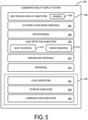
- FIG. 5 shows a block diagram of an example augmented reality display system 500.
- the augmented reality display system 500 includes one or more lenses 502 that form a part of a see-through display subsystem 504, such that images may be displayed via lenses 502 (e.g. via projection onto lenses 502, waveguide system(s) incorporated into lenses 502, and/or in any other suitable manner) while a real-world background is viewable through the lenses 502.
- the augmented reality display system 500 further includes one or more outward-facing image sensors 506 configured to acquire images of a real-world environment being viewed by a user, and may include one or more microphones 508 configured to detect sounds, such as voice commands from a user, ambient sounds, or sounds output as physical manifestations of devices in the environment.
- the outward-facing image sensors 506 may include one or more depth sensor(s) and/or one or more two-dimensional image sensor(s) (e.g. RGB image sensors).
- the augmented reality display system 500 may display video-based augmented reality images via a viewfinder mode using data from an outward-facing image sensor, rather than via a see-through display subsystem.
- the display system 500 may further include a gaze detection subsystem 510 configured to detect a gaze of a user for detecting user input, for example, for interacting with devices, physical manifestations thereof, displayed virtual objects, and/or for performing other computing device actions.
- the gaze detection subsystem 510 may be configured to determine gaze directions of each of a user's eyes in any suitable manner.
- the gaze detection subsystem 510 comprises one or more glint sources 512, such as infrared light sources configured to cause a glint of light to reflect from each eyeball of a user, and one or more image sensor(s) 514, such as inward-facing sensors, configured to capture an image of each eyeball of the user.
- the gaze detection subsystem 510 may have any suitable number and arrangement of light sources and image sensors. In other examples, the gaze detection subsystem 510 may be omitted.
- the display system 500 also may include additional sensors, as mentioned above.
- the display system 500 may include non-imaging sensor(s) 516, examples of which may include but are not limited to an accelerometer, a gyroscopic sensor, a global positioning system (GPS) sensor, and an inertial measurement unit (IMU).
- Such sensor(s) may help to determine the position, location, and/or orientation of the display device within the environment, which may help provide accurate tracking of the display device with regard to the real-world environment and locations of devices and/or physical manifestations in the environment.
- Such tracking may be used to appropriately modify outputs in an augmented reality setting, e.g. emitting virtual lights, sounds, objects, notifications, user interface elements, etc.
- Motion sensors as well as the microphone(s) 508 and the gaze detection subsystem 510, also may be employed as user input devices, such that a user may interact with the display system 500 via gestures of the eye, neck and/or head, as well as via verbal commands. It will be understood that sensors illustrated in FIG. 5 are shown for the purpose of example and are not intended to be limiting in any manner, as any other suitable sensors and/or combination of sensors may be utilized.
- Display system 500 further includes one or more speaker(s) 518, for example, to provide audio outputs to a user for user interactions.
- Display system 500 further includes a controller 520 having a logic subsystem 522 and a storage subsystem 524 in communication with the sensors, gaze detection subsystem 510, display subsystem 504, and/or other components.
- Storage subsystem 524 comprises instructions stored thereon that are executable by logic subsystem 522, for example, to perform various tasks related to the identification and localization of devices in the environment, as disclosed herein.
- Logic subsystem 522 includes one or more physical devices configured to execute instructions.
- the communication subsystem 526 is configured to communicatively couple the display system 500 with one or more other computing devices.
- Logic subsystem 522, storage subsystem 524, and communication subsystem 526 are described in more detail below in regard to computing system 600.
- the see-through display subsystem 504 may be used to present a visual representation of data held by storage subsystem 524.
- This visual representation may take the form of an augmented reality image and/or a graphical user interface (GUI) comprising graphical user interface elements.
- GUI graphical user interface
- the state of see-through display subsystem 504 may likewise be transformed to visually represent changes in the underlying data.
- the see-through display subsystem 504 may include one or more display devices utilizing virtually any type of technology. Such display devices may be combined with the logic subsystem 522 and/or the storage subsystem 524 in a shared enclosure, or such display devices may be peripheral display devices.
- the depicted display system 500 is described for the purpose of example, and thus is not meant to be limiting. It is to be further understood that the display system may include additional and/or alternative sensors, cameras, microphones, input devices, output devices, etc. than those shown without departing from the scope of this disclosure.
- the display system 500 may be implemented as a virtual realty display system rather than an augmented reality system.
- the physical configuration of a display device and its various sensors and subcomponents may take a variety of different forms without departing from the scope of this disclosure.
- the methods and processes described herein may be tied to a computing system of one or more computing devices.
- such methods and processes may be implemented as a computer-application program or service, an application-programming interface (API), a library, and/or other computer-program product.
- API application-programming interface
- FIG. 6 schematically shows a non-limiting embodiment of a computing system 600 that can enact one or more of the methods and processes described above.
- Computing system 600 is shown in simplified form.
- Computing system 600 may take the form of one or more personal computers, server computers, tablet computers, home-entertainment computers, network computing devices, gaming devices, mobile computing devices, mobile communication devices (e.g., smart phone), and/or other computing devices.
- computing system 600 may represent augmented reality device 102, device 108, controller 322, or any suitable device identified by the augmented reality device in a real-world environment.
- Computing system 600 includes a logic subsystem 602 and a storage subsystem 604.
- Computing system 600 may optionally include a display subsystem 606, input subsystem 608, communication subsystem 610, and/or other components not shown in FIG. 6 .
- Logic subsystem 602 includes one or more physical devices configured to execute instructions.
- the logic machine may be configured to execute instructions that are part of one or more applications, services, programs, routines, libraries, objects, components, data structures, or other logical constructs.
- Such instructions may be implemented to perform a task, implement a data type, transform the state of one or more components, achieve a technical effect, or otherwise arrive at a desired result.
- the logic subsystem 602 may include one or more processors configured to execute software instructions. Additionally or alternatively, the logic subsystem 602 may include one or more hardware or firmware logic machines configured to execute hardware or firmware instructions. Processors of the logic subsystem 602 may be single-core or multicore, and the instructions executed thereon may be configured for sequential, parallel, and/or distributed processing. Individual components of the logic subsystem 602 optionally may be distributed among two or more separate devices, which may be remotely located and/or configured for coordinated processing. Aspects of the logic subsystem 602 may be virtualized and executed by remotely accessible, networked computing devices configured in a cloud-computing configuration.
- Storage subsystem 604 includes one or more physical devices configured to hold instructions executable by the logic machine to implement the methods and processes described herein. When such methods and processes are implemented, the state of storage subsystem 604 may be transformed-e.g., to hold different data.
- Storage subsystem 604 may include removable and/or built-in devices.
- Storage subsystem 604 may include optical memory (e.g., CD, DVD, HD-DVD, Blu-Ray Disc, etc.), semiconductor memory (e.g., RAM, EPROM, EEPROM, etc.), and/or magnetic memory (e.g., hard-disk drive, floppy-disk drive, tape drive, MRAM, etc.), among others.
- Storage subsystem 604 may include volatile, nonvolatile, dynamic, static, read/write, read-only, random-access, sequential-access, location-addressable, file-addressable, and/or content-addressable devices.
- storage subsystem 604 includes one or more physical devices.
- aspects of the instructions described herein alternatively may be propagated by a communication medium (e.g., an electromagnetic signal, an optical signal, etc.), as opposed to being stored on a physical storage device.
- a communication medium e.g., an electromagnetic signal, an optical signal, etc.
- logic subsystem 602 and storage subsystem 604 may be integrated together into one or more hardware-logic components.
- Such hardware-logic components may include field-programmable gate arrays (FPGAs), program- and application-specific integrated circuits (PASIC / ASICs), program- and application-specific standard products (PSSP / ASSPs), system-on-a-chip (SOC), and complex programmable logic devices (CPLDs), for example.
- FPGAs field-programmable gate arrays
- PASIC / ASICs program- and application-specific integrated circuits
- PSSP / ASSPs program- and application-specific standard products
- SOC system-on-a-chip
- CPLDs complex programmable logic devices
- program may be used to describe an aspect of computing system 600 implemented to perform a particular function.
- a program may be instantiated via logic subsystem 602 executing instructions held by storage subsystem 604. It will be understood that different modules, programs, and/or engines may be instantiated from the same application, service, code block, object, library, routine, API, function, etc. Likewise, the same program may be instantiated by different applications, services, code blocks, objects, routines, APIs, functions, etc.
- program may encompass individual or groups of executable files, data files, libraries, drivers, scripts, database records, etc.
- a "service,” as used herein, is an application program executable across multiple user sessions.
- a service may be available to one or more system components, programs, and/or other services.
- a service may run on one or more server-computing devices.
- display subsystem 606 may be used to present a visual representation of data held by storage subsystem 604.
- This visual representation may take the form of a graphical user interface (GUI).
- GUI graphical user interface
- Display subsystem 606 may include one or more display devices utilizing virtually any type of technology. Such display devices may be combined with logic subsystem 602 and/or storage subsystem 604 in a shared enclosure, or such display devices may be peripheral display devices.
- input subsystem 608 may comprise or interface with one or more user-input devices such as a keyboard, mouse, touch screen, or game controller.
- the input subsystem may comprise or interface with selected natural user input (NUI) componentry.
- NUI natural user input
- Such componentry may be integrated or peripheral, and the transduction and/or processing of input actions may be handled on- or off-board.
- NUI componentry may include a microphone for speech and/or voice recognition; an infrared, color, stereoscopic, and/or depth camera for machine vision and/or gesture recognition; a head tracker, eye tracker, accelerometer, and/or gyroscope for motion detection and/or intent recognition; as well as electric-field sensing componentry for assessing brain activity.
- communication subsystem 610 may be configured to communicatively couple computing system 600 with one or more other computing devices.
- Communication subsystem 610 may include wired and/or wireless communication devices compatible with one or more different communication protocols.
- the communication subsystem may be configured for communication via a wireless telephone network, or a wired or wireless local- or wide-area network.
- the communication subsystem may allow computing system 610 to send and/or receive messages to and/or from other devices via a network such as the Internet.
Landscapes
- Engineering & Computer Science (AREA)
- Physics & Mathematics (AREA)
- General Physics & Mathematics (AREA)
- Theoretical Computer Science (AREA)
- General Engineering & Computer Science (AREA)
- Optics & Photonics (AREA)
- Software Systems (AREA)
- Computer Hardware Design (AREA)
- Computer Graphics (AREA)
- Signal Processing (AREA)
- Acoustics & Sound (AREA)
- Human Computer Interaction (AREA)
- Otolaryngology (AREA)
- General Health & Medical Sciences (AREA)
- Health & Medical Sciences (AREA)
- Computer Vision & Pattern Recognition (AREA)
- User Interface Of Digital Computer (AREA)
- Controls And Circuits For Display Device (AREA)
Claims (10)
- Verfahren zum Steuern einer tragbaren Rechenvorrichtung (301, 500) für erweiterte Realität,
wobei die tragbare Rechenvorrichtung (301, 500) für erweiterte Realität einen oder mehrere Bildsensoren (306), ein Mikrofonarray (308), ein Kommunikationsteilsystem (526) und eine durchsichtige Anzeige (302) umfasst, wobei das Verfahren (400) Folgendes umfasst:- Herstellen (402) eines Koordinatenrahmens für eine Umgebung auf Basis von Daten von mindestens einem von einem oder mehreren Bildsensoren (306) und einem oder mehreren Akustiksensoren (308);- Durchführen von Kommunikation (406) mit einer Vorrichtung in der Umgebung (108) über ein Kommunikationsteilsystem (526), um die Vorrichtung in der Umgebung (108) anzuleiten, eine physische Manifestation der Vorrichtung in der Umgebung (108) zu verändern, wobei die physische Manifestation mindestens eines von einem Anzeigeausgang und einem Audioausgang ist, der durch den mindestens einen von einem oder mehreren Bildsensoren (306) und einem oder mehreren Akustiksensoren (308) erfassbar ist;- Ermitteln (420), über den mindestens einen von einem oder mehreren Bildsensoren (306) und einem oder mehreren Akustiksensoren (308), eines Standorts der physischen Manifestation der Vorrichtung auf Basis einer Veränderung der physischen Manifestation der Vorrichtung in der Umgebung;- Zuweisen (426) eines Vorrichtungsstandorts für die Vorrichtung in der Umgebung in dem Koordinatenrahmen auf Basis des Standorts der physischen Manifestation;- Modifizieren (428) eines erweiterten Realitätsbilds, das über die durchsichtige Anzeige (302) angezeigt wird, durch die tragbare Rechenvorrichtung (301, 500) für erweiterte Realität auf Basis einer Änderung einer relativen Position zwischen der tragbaren Rechenvorrichtung (301, 500) für erweiterte Realität und der Vorrichtung in der Umgebung, indem ein Abschnitt des erweiterten Realitätsbilds modifiziert wird, der dem Vorrichtungsstandort entspricht, um Verdeckung einer Sicht der Vorrichtung in der Umgebung durch das erweiterte Realitätsbild zu vermeiden. - Verfahren nach Anspruch 1, wobei Ermitteln des Standorts der physischen Manifestation umfasst, ein Licht zu erfassen, das von der Vorrichtung in der Umgebung gesteuert wird.
- Verfahren nach einem vorstehenden Anspruch, wobei Ermitteln des Standorts der physischen Manifestation umfasst, einen Standort eines Anzeigebildschirms (110) der Vorrichtung in der Umgebung (108) zu erfassen.
- Verfahren nach einem vorstehenden Anspruch, weiter umfassend Ermitteln der Vorrichtung in der Umgebung über ein drahtloses Netzwerk.
- Verfahren nach einem vorstehenden Anspruch, weiter umfassend Verfolgen von Bewegung der tragbaren Rechenvorrichtung für erweiterte Realität über einen Trägheitsbewegungssensor und Aktualisieren des erweiterten Realitätsbilds auf Basis des Verfolgens, um zu vermeiden, dass die physische Manifestation verdeckt wird.
- Tragbare Anzeigevorrichtung (301) für erweiterte Realität, die Folgendes umfasst:- eine durchsichtige Anzeigevorrichtung (302);- mindestens eines von einem oder mehreren Bildsensoren und einem Mikrofonarray (308);- ein Kommunikationsteilsystem (526);- eine Logikvorrichtung (522); und- eine Speichervorrichtung (524), umfassend Anweisungen, die von der Logikvorrichtung ausführbar sind, wobei die Logikvorrichtung für Folgendes konfiguriert ist- Herstellen (402) eines Koordinatenrahmens für eine Umgebung auf Basis von Daten von dem mindestens einen von einem oder mehreren Bildsensoren und einem oder mehreren Akustiksensoren,- Durchführen von Kommunikation mit einer Vorrichtung in der Umgebung (108) über das Kommunikationsteilsystem (526), um die Vorrichtung in der Umgebung anzuleiten (408), eine physische Manifestation der Vorrichtung in der Umgebung zu verändern, wobei die physische Manifestation von dem mindestens einen von einem oder mehreren Bildsensoren und einem oder mehreren Akustiksensoren erfassbar ist, wobei die physische Manifestation mindestens eines von einem Anzeigeausgang und einem Audioausgang ist, der von dem mindestens einen von einem oder mehreren Bildsensoren und einem oder mehreren Akustiksensoren erfassbar ist;- Erfassen (420), über den mindestens einen von einem oder mehreren Bildsensoren und einem oder mehreren Akustiksensoren, eines Standorts der physischen Manifestation auf Basis einer Veränderung der physischen Manifestation der Vorrichtung in der Umgebung,- Zuweisen (426) eines Vorrichtungsstandorts für die Vorrichtung in der Umgebung in dem Koordinatenrahmen auf Basis des Standorts der physischen Manifestation und- Modifizieren (428) eines Ausgangs der Anzeigevorrichtung für erweiterte Realität auf Basis einer Änderung einer relativen Position zwischen der Anzeigevorrichtung für erweiterte Realität und der physischen Manifestation in der Umgebung, um Verdeckung einer Sicht der Vorrichtung in der Umgebung zu vermeiden, indem ein Abschnitt eines erweiterten Realitätsbilds modifiziert wird, der dem Vorrichtungsstandort entspricht, um Verdeckung einer Sicht der Vorrichtung in der Umgebung durch das erweiterte Realitätsbild zu vermeiden.
- Anzeigevorrichtung für erweiterte Realität nach Anspruch 6, wobei die physische Manifestation ein Licht umfasst, das von der Vorrichtung in der Umgebung gesteuert wird.
- Anzeigevorrichtung für erweiterte Realität nach einem der Ansprüche 6 bis 7, wobei die physische Manifestation Inhalt umfasst, der auf einer Anzeige der Vorrichtung in der Umgebung angezeigt wird.
- Anzeigevorrichtung für erweiterte Realität nach einem der Ansprüche 6 bis 8, wobei die Anweisungen weiter ausführbar sind, um die Vorrichtung in der Umgebung über ein drahtloses Netzwerk zu ermitteln.
- Anzeigevorrichtung für erweiterte Realität nach einem der Ansprüche 6 bis 9, wobei die Anweisungen ausführbar sind, um das erweiterte Realitätsbild zu modifizieren, um zu vermeiden, dass die physische Manifestation von dem erweiterten Realitätsbild verdeckt wird.
Applications Claiming Priority (2)
| Application Number | Priority Date | Filing Date | Title |
|---|---|---|---|
| US14/843,596 US9865091B2 (en) | 2015-09-02 | 2015-09-02 | Localizing devices in augmented reality environment |
| PCT/US2016/044951 WO2017039911A1 (en) | 2015-09-02 | 2016-08-01 | Localizing devices in an augmented reality environment |
Publications (2)
| Publication Number | Publication Date |
|---|---|
| EP3345073A1 EP3345073A1 (de) | 2018-07-11 |
| EP3345073B1 true EP3345073B1 (de) | 2022-01-26 |
Family
ID=56684758
Family Applications (1)
| Application Number | Title | Priority Date | Filing Date |
|---|---|---|---|
| EP16751426.4A Active EP3345073B1 (de) | 2015-09-02 | 2016-08-01 | Ortung von vorrichtungen in einer erweiterten realitätsumgebung |
Country Status (4)
| Country | Link |
|---|---|
| US (1) | US9865091B2 (de) |
| EP (1) | EP3345073B1 (de) |
| CN (1) | CN108027649B (de) |
| WO (1) | WO2017039911A1 (de) |
Families Citing this family (33)
| Publication number | Priority date | Publication date | Assignee | Title |
|---|---|---|---|---|
| US10484824B1 (en) * | 2015-06-26 | 2019-11-19 | Lucasfilm Entertainment Company Ltd. | Content presentation and layering across multiple devices |
| JP6017664B1 (ja) * | 2015-12-28 | 2016-11-02 | 株式会社コロプラ | 情報処理方法及び情報処理プログラム |
| US9767606B2 (en) * | 2016-01-12 | 2017-09-19 | Lenovo (Singapore) Pte. Ltd. | Automatic modification of augmented reality objects |
| US10031718B2 (en) * | 2016-06-14 | 2018-07-24 | Microsoft Technology Licensing, Llc | Location based audio filtering |
| US10514752B2 (en) * | 2016-07-07 | 2019-12-24 | Google Llc | Methods and apparatus to determine objects to present in virtual reality environments |
| US10482749B2 (en) * | 2017-01-11 | 2019-11-19 | Universal Entertainment Corporation | Controlling electronic device alerts by operating head mounted display |
| US10620817B2 (en) * | 2017-01-13 | 2020-04-14 | International Business Machines Corporation | Providing augmented reality links to stored files |
| US10146300B2 (en) | 2017-01-25 | 2018-12-04 | Lenovo Enterprise Solutions (Singapore) Pte. Ltd. | Emitting a visual indicator from the position of an object in a simulated reality emulation |
| JP2018151851A (ja) * | 2017-03-13 | 2018-09-27 | セイコーエプソン株式会社 | 透過型表示装置、表示制御方法、およびコンピュータープログラム |
| US10447841B2 (en) * | 2017-06-05 | 2019-10-15 | Bose Corporation | Wireless pairing and control using spatial location and indication to aid pairing |
| CN107767462B (zh) * | 2017-10-16 | 2023-08-25 | 北京视据科技有限公司 | 一种非穿戴增强现实全息展示方法及展示系统 |
| US10551933B2 (en) | 2017-11-02 | 2020-02-04 | International Business Machines Corporation | Media sharing with visualized positioning layout in real time |
| FR3074307B1 (fr) * | 2017-11-30 | 2019-12-20 | Safran Electronics & Defense | Dispositif de vision pour pilote d aeronef |
| US10818086B2 (en) * | 2018-02-09 | 2020-10-27 | Lenovo (Singapore) Pte. Ltd. | Augmented reality content characteristic adjustment |
| US11709370B2 (en) | 2018-05-08 | 2023-07-25 | Apple Inc. | Presentation of an enriched view of a physical setting |
| WO2020025142A1 (en) * | 2018-08-03 | 2020-02-06 | Huawei Technologies Co., Ltd. | Providing location-based augmented reality content |
| US20200065771A1 (en) * | 2018-08-24 | 2020-02-27 | CareerBuilder, LLC | Location-based augmented reality for job seekers |
| US10893043B1 (en) * | 2018-09-12 | 2021-01-12 | Massachusetts Mutual Life Insurance Company | Systems and methods for secure display of data on computing devices |
| CN111258520B (zh) * | 2018-12-03 | 2021-09-14 | 广东虚拟现实科技有限公司 | 显示方法、装置、终端设备及存储介质 |
| US10902685B2 (en) | 2018-12-13 | 2021-01-26 | John T. Daly | Augmented reality remote authoring and social media platform and system |
| US11675200B1 (en) * | 2018-12-14 | 2023-06-13 | Google Llc | Antenna methods and systems for wearable devices |
| JP7238456B2 (ja) * | 2019-02-21 | 2023-03-14 | セイコーエプソン株式会社 | 表示システム、情報処理装置の制御プログラム、及び情報処理装置の制御方法 |
| US11055919B2 (en) | 2019-04-26 | 2021-07-06 | Google Llc | Managing content in augmented reality |
| US11151792B2 (en) | 2019-04-26 | 2021-10-19 | Google Llc | System and method for creating persistent mappings in augmented reality |
| US11163997B2 (en) | 2019-05-05 | 2021-11-02 | Google Llc | Methods and apparatus for venue based augmented reality |
| US11210932B2 (en) | 2019-05-21 | 2021-12-28 | Apple Inc. | Discovery of and connection to remote devices |
| US12470892B2 (en) | 2020-04-23 | 2025-11-11 | Comcast Cable Communications, Llc | Extended reality localization |
| CN111651043B (zh) * | 2020-05-29 | 2021-10-12 | 北京航空航天大学 | 一种支持定制化多通道交互的增强现实系统 |
| WO2022182668A1 (en) | 2021-02-23 | 2022-09-01 | Dathomir Laboratories Llc | Digital assistant interactions in extended reality |
| WO2022182744A1 (en) | 2021-02-23 | 2022-09-01 | Dathomir Laboratories Llc | Digital assistant interactions in copresence sessions |
| EP4369075A4 (de) | 2021-09-29 | 2024-11-20 | Samsung Electronics Co., Ltd. | Elektronische vorrichtung zur bereitstellung eines dienstes für erweiterte realität und betriebsverfahren dafür |
| CN114416184B (zh) * | 2021-12-06 | 2023-08-01 | 北京航空航天大学 | 基于虚拟现实设备的存内计算方法及装置 |
| US12217372B2 (en) | 2022-10-17 | 2025-02-04 | T-Mobile Usa, Inc. | Generating mixed reality content based on data from a wireless device |
Family Cites Families (26)
| Publication number | Priority date | Publication date | Assignee | Title |
|---|---|---|---|---|
| US6982697B2 (en) * | 2002-02-07 | 2006-01-03 | Microsoft Corporation | System and process for selecting objects in a ubiquitous computing environment |
| US7296747B2 (en) | 2004-04-20 | 2007-11-20 | Michael Rohs | Visual code system for camera-equipped mobile devices and applications thereof |
| KR100594127B1 (ko) | 2004-11-16 | 2006-06-28 | 삼성전자주식회사 | 블루투스 기기에서 본딩 프로세스 방법 및 장치 |
| KR101246293B1 (ko) * | 2006-04-24 | 2013-03-21 | 삼성전자주식회사 | 홈 네트워크에서 사용자 인터페이스 방법 및 장치와 그전자기기 및 저장 매체 |
| KR20090018471A (ko) * | 2007-08-17 | 2009-02-20 | 삼성전자주식회사 | 디스플레이장치 및 그 제어방법 |
| US8736427B2 (en) | 2008-09-03 | 2014-05-27 | Apple Inc. | Intelligent infrared remote pairing |
| US8363098B2 (en) * | 2008-09-16 | 2013-01-29 | Plantronics, Inc. | Infrared derived user presence and associated remote control |
| US8970690B2 (en) * | 2009-02-13 | 2015-03-03 | Metaio Gmbh | Methods and systems for determining the pose of a camera with respect to at least one object of a real environment |
| US20110065496A1 (en) | 2009-09-11 | 2011-03-17 | Wms Gaming, Inc. | Augmented reality mechanism for wagering game systems |
| US8879994B2 (en) | 2009-10-02 | 2014-11-04 | Blackberry Limited | Methods and devices for facilitating Bluetooth pairing using a camera as a barcode scanner |
| US8116685B2 (en) | 2010-01-26 | 2012-02-14 | Samsung Electronics Co., Inc. | System and method for visual pairing of mobile devices |
| US8970733B2 (en) | 2010-05-28 | 2015-03-03 | Robert Bosch Gmbh | Visual pairing and data exchange between devices using barcodes for data exchange with mobile navigation systems |
| WO2012015956A2 (en) | 2010-07-30 | 2012-02-02 | Gravity Jack, Inc. | Augmented reality and location determination methods and apparatus |
| US8845110B1 (en) | 2010-12-23 | 2014-09-30 | Rawles Llc | Powered augmented reality projection accessory display device |
| US20120198531A1 (en) | 2011-01-31 | 2012-08-02 | Microsoft Corporation | Multi-device session pairing using a visual tag |
| US8446364B2 (en) | 2011-03-04 | 2013-05-21 | Interphase Corporation | Visual pairing in an interactive display system |
| US8405729B2 (en) | 2011-05-11 | 2013-03-26 | Sony Corporation | System and method for pairing hand-held devices utilizing a front-facing camera |
| EP2837167B1 (de) * | 2012-04-12 | 2018-12-19 | Telefonaktiebolaget LM Ericsson (publ) | Paarung eines mobilen endgeräts mit einer drahtlosen vorrichtung |
| KR101861380B1 (ko) * | 2012-07-16 | 2018-05-28 | 마이크로소프트 테크놀로지 라이센싱, 엘엘씨 | 헤드 마운트 디스플레이를 이용한 컨텐츠 출력 방법 및 이를 위한 헤드 마운트 디스플레이 |
| KR101989893B1 (ko) | 2012-10-29 | 2019-09-30 | 엘지전자 주식회사 | 헤드 마운트 디스플레이 및 이를 이용한 오디오 신호 출력 방법 |
| US9063692B2 (en) | 2012-12-21 | 2015-06-23 | Nokia Technologies Oy | Method and apparatus for sharing content |
| KR102019124B1 (ko) * | 2013-01-04 | 2019-09-06 | 엘지전자 주식회사 | 헤드 마운트 디스플레이 및 그 제어 방법 |
| KR102161510B1 (ko) * | 2013-09-02 | 2020-10-05 | 엘지전자 주식회사 | 포터블 디바이스 및 그 제어 방법 |
| CA2888943C (en) * | 2013-10-03 | 2015-08-18 | Sulon Technologies Inc. | Augmented reality system and method for positioning and mapping |
| KR102133843B1 (ko) | 2013-10-31 | 2020-07-14 | 엘지전자 주식회사 | 3차원 프린팅의 프로세스를 인디케이팅하는 헤드 마운티드 디스플레이 및 그 제어 방법 |
| KR102182161B1 (ko) * | 2014-02-20 | 2020-11-24 | 엘지전자 주식회사 | Hmd 및 그 제어 방법 |
-
2015
- 2015-09-02 US US14/843,596 patent/US9865091B2/en active Active
-
2016
- 2016-08-01 EP EP16751426.4A patent/EP3345073B1/de active Active
- 2016-08-01 CN CN201680050915.0A patent/CN108027649B/zh active Active
- 2016-08-01 WO PCT/US2016/044951 patent/WO2017039911A1/en not_active Ceased
Also Published As
| Publication number | Publication date |
|---|---|
| CN108027649A (zh) | 2018-05-11 |
| US20170061692A1 (en) | 2017-03-02 |
| CN108027649B (zh) | 2021-03-02 |
| WO2017039911A1 (en) | 2017-03-09 |
| US9865091B2 (en) | 2018-01-09 |
| EP3345073A1 (de) | 2018-07-11 |
Similar Documents
| Publication | Publication Date | Title |
|---|---|---|
| EP3345073B1 (de) | Ortung von vorrichtungen in einer erweiterten realitätsumgebung | |
| US11630509B2 (en) | Determining user intent based on attention values | |
| US11429186B2 (en) | Location-based entity selection using gaze tracking | |
| EP3619599B1 (de) | Mit einem gemeinsam genutzten anker gezeigter virtueller inhalt | |
| US10672103B2 (en) | Virtual object movement | |
| CN107003738B (zh) | 注视目标应用启动器 | |
| KR102493749B1 (ko) | 동적 환경에서의 좌표 프레임의 결정 | |
| US10789779B2 (en) | Location-based holographic experience | |
| US10338392B2 (en) | Identification of augmented reality image display position | |
| US12499680B2 (en) | Method and system for encoded optical communication using a modulated light source | |
| EP3782015B1 (de) | Dreidimensionale push-benachrichtigung | |
| US10055888B2 (en) | Producing and consuming metadata within multi-dimensional data | |
| US9584915B2 (en) | Spatial audio with remote speakers | |
| US10564915B2 (en) | Displaying content based on positional state | |
| KR102911932B1 (ko) | 웨어러블 장치를 이용한 제어가능한 장치의 위치 식별 | |
| EP4432244A1 (de) | Augment-graph zur selektiven gemeinsamen nutzung von augments über anwendungen oder benutzer hinweg | |
| EP4432243A1 (de) | Augment-graph zur selektiven gemeinsamen nutzung von augments über anwendungen oder benutzer hinweg | |
| KR20250015593A (ko) | 진동을 출력하도록 외부 전자 장치를 제어하기 위한 전자 장치, 방법, 및 컴퓨터 판독 가능 저장 매체 |
Legal Events
| Date | Code | Title | Description |
|---|---|---|---|
| STAA | Information on the status of an ep patent application or granted ep patent |
Free format text: STATUS: THE INTERNATIONAL PUBLICATION HAS BEEN MADE |
|
| PUAI | Public reference made under article 153(3) epc to a published international application that has entered the european phase |
Free format text: ORIGINAL CODE: 0009012 |
|
| STAA | Information on the status of an ep patent application or granted ep patent |
Free format text: STATUS: REQUEST FOR EXAMINATION WAS MADE |
|
| 17P | Request for examination filed |
Effective date: 20180212 |
|
| AK | Designated contracting states |
Kind code of ref document: A1 Designated state(s): AL AT BE BG CH CY CZ DE DK EE ES FI FR GB GR HR HU IE IS IT LI LT LU LV MC MK MT NL NO PL PT RO RS SE SI SK SM TR |
|
| AX | Request for extension of the european patent |
Extension state: BA ME |
|
| DAV | Request for validation of the european patent (deleted) | ||
| DAX | Request for extension of the european patent (deleted) | ||
| STAA | Information on the status of an ep patent application or granted ep patent |
Free format text: STATUS: EXAMINATION IS IN PROGRESS |
|
| 17Q | First examination report despatched |
Effective date: 20201208 |
|
| RAP3 | Party data changed (applicant data changed or rights of an application transferred) |
Owner name: MICROSOFT TECHNOLOGY LICENSING, LLC |
|
| GRAP | Despatch of communication of intention to grant a patent |
Free format text: ORIGINAL CODE: EPIDOSNIGR1 |
|
| STAA | Information on the status of an ep patent application or granted ep patent |
Free format text: STATUS: GRANT OF PATENT IS INTENDED |
|
| INTG | Intention to grant announced |
Effective date: 20210910 |
|
| RAP3 | Party data changed (applicant data changed or rights of an application transferred) |
Owner name: MICROSOFT TECHNOLOGY LICENSING, LLC |
|
| GRAS | Grant fee paid |
Free format text: ORIGINAL CODE: EPIDOSNIGR3 |
|
| GRAA | (expected) grant |
Free format text: ORIGINAL CODE: 0009210 |
|
| STAA | Information on the status of an ep patent application or granted ep patent |
Free format text: STATUS: THE PATENT HAS BEEN GRANTED |
|
| AK | Designated contracting states |
Kind code of ref document: B1 Designated state(s): AL AT BE BG CH CY CZ DE DK EE ES FI FR GB GR HR HU IE IS IT LI LT LU LV MC MK MT NL NO PL PT RO RS SE SI SK SM TR |
|
| REG | Reference to a national code |
Ref country code: GB Ref legal event code: FG4D |
|
| REG | Reference to a national code |
Ref country code: CH Ref legal event code: EP |
|
| REG | Reference to a national code |
Ref country code: AT Ref legal event code: REF Ref document number: 1465797 Country of ref document: AT Kind code of ref document: T Effective date: 20220215 |
|
| REG | Reference to a national code |
Ref country code: IE Ref legal event code: FG4D |
|
| REG | Reference to a national code |
Ref country code: DE Ref legal event code: R096 Ref document number: 602016068654 Country of ref document: DE |
|
| REG | Reference to a national code |
Ref country code: LT Ref legal event code: MG9D |
|
| REG | Reference to a national code |
Ref country code: NL Ref legal event code: MP Effective date: 20220126 |
|
| REG | Reference to a national code |
Ref country code: AT Ref legal event code: MK05 Ref document number: 1465797 Country of ref document: AT Kind code of ref document: T Effective date: 20220126 |
|
| PG25 | Lapsed in a contracting state [announced via postgrant information from national office to epo] |
Ref country code: NL Free format text: LAPSE BECAUSE OF FAILURE TO SUBMIT A TRANSLATION OF THE DESCRIPTION OR TO PAY THE FEE WITHIN THE PRESCRIBED TIME-LIMIT Effective date: 20220126 |
|
| PG25 | Lapsed in a contracting state [announced via postgrant information from national office to epo] |
Ref country code: SE Free format text: LAPSE BECAUSE OF FAILURE TO SUBMIT A TRANSLATION OF THE DESCRIPTION OR TO PAY THE FEE WITHIN THE PRESCRIBED TIME-LIMIT Effective date: 20220126 Ref country code: RS Free format text: LAPSE BECAUSE OF FAILURE TO SUBMIT A TRANSLATION OF THE DESCRIPTION OR TO PAY THE FEE WITHIN THE PRESCRIBED TIME-LIMIT Effective date: 20220126 Ref country code: PT Free format text: LAPSE BECAUSE OF FAILURE TO SUBMIT A TRANSLATION OF THE DESCRIPTION OR TO PAY THE FEE WITHIN THE PRESCRIBED TIME-LIMIT Effective date: 20220526 Ref country code: NO Free format text: LAPSE BECAUSE OF FAILURE TO SUBMIT A TRANSLATION OF THE DESCRIPTION OR TO PAY THE FEE WITHIN THE PRESCRIBED TIME-LIMIT Effective date: 20220426 Ref country code: LT Free format text: LAPSE BECAUSE OF FAILURE TO SUBMIT A TRANSLATION OF THE DESCRIPTION OR TO PAY THE FEE WITHIN THE PRESCRIBED TIME-LIMIT Effective date: 20220126 Ref country code: HR Free format text: LAPSE BECAUSE OF FAILURE TO SUBMIT A TRANSLATION OF THE DESCRIPTION OR TO PAY THE FEE WITHIN THE PRESCRIBED TIME-LIMIT Effective date: 20220126 Ref country code: ES Free format text: LAPSE BECAUSE OF FAILURE TO SUBMIT A TRANSLATION OF THE DESCRIPTION OR TO PAY THE FEE WITHIN THE PRESCRIBED TIME-LIMIT Effective date: 20220126 Ref country code: BG Free format text: LAPSE BECAUSE OF FAILURE TO SUBMIT A TRANSLATION OF THE DESCRIPTION OR TO PAY THE FEE WITHIN THE PRESCRIBED TIME-LIMIT Effective date: 20220426 |
|
| PG25 | Lapsed in a contracting state [announced via postgrant information from national office to epo] |
Ref country code: PL Free format text: LAPSE BECAUSE OF FAILURE TO SUBMIT A TRANSLATION OF THE DESCRIPTION OR TO PAY THE FEE WITHIN THE PRESCRIBED TIME-LIMIT Effective date: 20220126 Ref country code: LV Free format text: LAPSE BECAUSE OF FAILURE TO SUBMIT A TRANSLATION OF THE DESCRIPTION OR TO PAY THE FEE WITHIN THE PRESCRIBED TIME-LIMIT Effective date: 20220126 Ref country code: GR Free format text: LAPSE BECAUSE OF FAILURE TO SUBMIT A TRANSLATION OF THE DESCRIPTION OR TO PAY THE FEE WITHIN THE PRESCRIBED TIME-LIMIT Effective date: 20220427 Ref country code: FI Free format text: LAPSE BECAUSE OF FAILURE TO SUBMIT A TRANSLATION OF THE DESCRIPTION OR TO PAY THE FEE WITHIN THE PRESCRIBED TIME-LIMIT Effective date: 20220126 Ref country code: AT Free format text: LAPSE BECAUSE OF FAILURE TO SUBMIT A TRANSLATION OF THE DESCRIPTION OR TO PAY THE FEE WITHIN THE PRESCRIBED TIME-LIMIT Effective date: 20220126 |
|
| PG25 | Lapsed in a contracting state [announced via postgrant information from national office to epo] |
Ref country code: IS Free format text: LAPSE BECAUSE OF FAILURE TO SUBMIT A TRANSLATION OF THE DESCRIPTION OR TO PAY THE FEE WITHIN THE PRESCRIBED TIME-LIMIT Effective date: 20220526 |
|
| REG | Reference to a national code |
Ref country code: DE Ref legal event code: R097 Ref document number: 602016068654 Country of ref document: DE |
|
| PG25 | Lapsed in a contracting state [announced via postgrant information from national office to epo] |
Ref country code: SM Free format text: LAPSE BECAUSE OF FAILURE TO SUBMIT A TRANSLATION OF THE DESCRIPTION OR TO PAY THE FEE WITHIN THE PRESCRIBED TIME-LIMIT Effective date: 20220126 Ref country code: SK Free format text: LAPSE BECAUSE OF FAILURE TO SUBMIT A TRANSLATION OF THE DESCRIPTION OR TO PAY THE FEE WITHIN THE PRESCRIBED TIME-LIMIT Effective date: 20220126 Ref country code: RO Free format text: LAPSE BECAUSE OF FAILURE TO SUBMIT A TRANSLATION OF THE DESCRIPTION OR TO PAY THE FEE WITHIN THE PRESCRIBED TIME-LIMIT Effective date: 20220126 Ref country code: EE Free format text: LAPSE BECAUSE OF FAILURE TO SUBMIT A TRANSLATION OF THE DESCRIPTION OR TO PAY THE FEE WITHIN THE PRESCRIBED TIME-LIMIT Effective date: 20220126 Ref country code: DK Free format text: LAPSE BECAUSE OF FAILURE TO SUBMIT A TRANSLATION OF THE DESCRIPTION OR TO PAY THE FEE WITHIN THE PRESCRIBED TIME-LIMIT Effective date: 20220126 Ref country code: CZ Free format text: LAPSE BECAUSE OF FAILURE TO SUBMIT A TRANSLATION OF THE DESCRIPTION OR TO PAY THE FEE WITHIN THE PRESCRIBED TIME-LIMIT Effective date: 20220126 |
|
| PG25 | Lapsed in a contracting state [announced via postgrant information from national office to epo] |
Ref country code: AL Free format text: LAPSE BECAUSE OF FAILURE TO SUBMIT A TRANSLATION OF THE DESCRIPTION OR TO PAY THE FEE WITHIN THE PRESCRIBED TIME-LIMIT Effective date: 20220126 |
|
| PLBE | No opposition filed within time limit |
Free format text: ORIGINAL CODE: 0009261 |
|
| STAA | Information on the status of an ep patent application or granted ep patent |
Free format text: STATUS: NO OPPOSITION FILED WITHIN TIME LIMIT |
|
| 26N | No opposition filed |
Effective date: 20221027 |
|
| PG25 | Lapsed in a contracting state [announced via postgrant information from national office to epo] |
Ref country code: SI Free format text: LAPSE BECAUSE OF FAILURE TO SUBMIT A TRANSLATION OF THE DESCRIPTION OR TO PAY THE FEE WITHIN THE PRESCRIBED TIME-LIMIT Effective date: 20220126 |
|
| PG25 | Lapsed in a contracting state [announced via postgrant information from national office to epo] |
Ref country code: MC Free format text: LAPSE BECAUSE OF FAILURE TO SUBMIT A TRANSLATION OF THE DESCRIPTION OR TO PAY THE FEE WITHIN THE PRESCRIBED TIME-LIMIT Effective date: 20220126 |
|
| REG | Reference to a national code |
Ref country code: CH Ref legal event code: PL |
|
| PG25 | Lapsed in a contracting state [announced via postgrant information from national office to epo] |
Ref country code: LU Free format text: LAPSE BECAUSE OF NON-PAYMENT OF DUE FEES Effective date: 20220801 Ref country code: LI Free format text: LAPSE BECAUSE OF NON-PAYMENT OF DUE FEES Effective date: 20220831 Ref country code: CH Free format text: LAPSE BECAUSE OF NON-PAYMENT OF DUE FEES Effective date: 20220831 |
|
| REG | Reference to a national code |
Ref country code: BE Ref legal event code: MM Effective date: 20220831 |
|
| P01 | Opt-out of the competence of the unified patent court (upc) registered |
Effective date: 20230429 |
|
| PG25 | Lapsed in a contracting state [announced via postgrant information from national office to epo] |
Ref country code: IT Free format text: LAPSE BECAUSE OF FAILURE TO SUBMIT A TRANSLATION OF THE DESCRIPTION OR TO PAY THE FEE WITHIN THE PRESCRIBED TIME-LIMIT Effective date: 20220126 Ref country code: IE Free format text: LAPSE BECAUSE OF NON-PAYMENT OF DUE FEES Effective date: 20220801 |
|
| PG25 | Lapsed in a contracting state [announced via postgrant information from national office to epo] |
Ref country code: BE Free format text: LAPSE BECAUSE OF NON-PAYMENT OF DUE FEES Effective date: 20220831 |
|
| PG25 | Lapsed in a contracting state [announced via postgrant information from national office to epo] |
Ref country code: HU Free format text: LAPSE BECAUSE OF FAILURE TO SUBMIT A TRANSLATION OF THE DESCRIPTION OR TO PAY THE FEE WITHIN THE PRESCRIBED TIME-LIMIT; INVALID AB INITIO Effective date: 20160801 |
|
| PG25 | Lapsed in a contracting state [announced via postgrant information from national office to epo] |
Ref country code: MK Free format text: LAPSE BECAUSE OF FAILURE TO SUBMIT A TRANSLATION OF THE DESCRIPTION OR TO PAY THE FEE WITHIN THE PRESCRIBED TIME-LIMIT Effective date: 20220126 Ref country code: CY Free format text: LAPSE BECAUSE OF FAILURE TO SUBMIT A TRANSLATION OF THE DESCRIPTION OR TO PAY THE FEE WITHIN THE PRESCRIBED TIME-LIMIT Effective date: 20220126 |
|
| PG25 | Lapsed in a contracting state [announced via postgrant information from national office to epo] |
Ref country code: MT Free format text: LAPSE BECAUSE OF FAILURE TO SUBMIT A TRANSLATION OF THE DESCRIPTION OR TO PAY THE FEE WITHIN THE PRESCRIBED TIME-LIMIT Effective date: 20220126 |
|
| PGFP | Annual fee paid to national office [announced via postgrant information from national office to epo] |
Ref country code: FR Payment date: 20240723 Year of fee payment: 9 |
|
| PGFP | Annual fee paid to national office [announced via postgrant information from national office to epo] |
Ref country code: DE Payment date: 20250724 Year of fee payment: 10 |
|
| PGFP | Annual fee paid to national office [announced via postgrant information from national office to epo] |
Ref country code: GB Payment date: 20250724 Year of fee payment: 10 |
|
| PG25 | Lapsed in a contracting state [announced via postgrant information from national office to epo] |
Ref country code: TR Free format text: LAPSE BECAUSE OF FAILURE TO SUBMIT A TRANSLATION OF THE DESCRIPTION OR TO PAY THE FEE WITHIN THE PRESCRIBED TIME-LIMIT Effective date: 20220126 |