EP3345162B1 - Visualisierung von oberflächenvolumenhybridmodellen in der medizinischen bildgebung - Google Patents
Visualisierung von oberflächenvolumenhybridmodellen in der medizinischen bildgebung Download PDFInfo
- Publication number
- EP3345162B1 EP3345162B1 EP15763757.0A EP15763757A EP3345162B1 EP 3345162 B1 EP3345162 B1 EP 3345162B1 EP 15763757 A EP15763757 A EP 15763757A EP 3345162 B1 EP3345162 B1 EP 3345162B1
- Authority
- EP
- European Patent Office
- Prior art keywords
- volume
- renderer
- rays
- rendering
- medical imaging
- Prior art date
- Legal status (The legal status is an assumption and is not a legal conclusion. Google has not performed a legal analysis and makes no representation as to the accuracy of the status listed.)
- Active
Links
Images
Classifications
-
- G—PHYSICS
- G06—COMPUTING OR CALCULATING; COUNTING
- G06T—IMAGE DATA PROCESSING OR GENERATION, IN GENERAL
- G06T15/00—Three-dimensional [3D] image rendering
- G06T15/06—Ray-tracing
-
- G—PHYSICS
- G06—COMPUTING OR CALCULATING; COUNTING
- G06T—IMAGE DATA PROCESSING OR GENERATION, IN GENERAL
- G06T2210/00—Indexing scheme for image generation or computer graphics
- G06T2210/41—Medical
Definitions
- the present embodiments relate to medical imaging.
- medical imaging the interior of a patient is scanned.
- Various approaches are possible, such as magnetic resonance (MR), computed tomography (CT), x-ray, fluoroscopy, ultrasound, positron emission tomography (PET), or single photon emission computed tomography (SPECT).
- MR magnetic resonance
- CT computed tomography
- PET positron emission tomography
- SPECT single photon emission computed tomography
- Three-dimensional (3D) visualization is a common practice to assess and record the internal conditions of patients.
- volumetric effects model a wide variety of natural and non-natural phenomena, both for real-time and offline visualization.
- 3D visualization may be difficult for medical imaging, particularly where the volume data from the scan is rendered with an added surface (e.g., a surface representing a model of an object in the scan volume of the patient).
- Rasterization is the most common hardware accelerated technique. Rasterization may not be suitable for rendering volumetric data and even advanced surface rendering effects (e.g., accurate lighting, transparency, shadows, etc.) remain challenging.
- advanced surface rendering effects e.g., accurate lighting, transparency, shadows, etc.
- offline rendering systems often use ray tracing, path tracing, and other advanced light transport simulations that naturally model the propagation of light within the model and lead to more realistic results with less development effort.
- These projection rendering approaches operate at a higher computational cost, but may be used for interactive and even real-time visualization.
- Rendering of surfaces embedded in a volume remains a challenging problem in the traditional volume visualization systems.
- a number of techniques exist which implement specific types of effects near the intersections of the two types of data e.g. surface transparency or ambient occlusions.
- existing renderers may use rasterization and apply the resulting depth buffer during volume integration. The resulting rendered volume is then composited over the rasterization result.
- Multi-pass rendering techniques such as depth peeling provide support for embedded transparent surfaces at a significant performance cost.
- Ray tracing with unified handling of both volume and surface data types enables a number of advanced visual effects that are not possible with traditional volume rendering or rasterization systems.
- the rendering of embedded surfaces is unified with the volumetric rendering.
- Using a unified or parallel ray tracing-based rendering system accurately computes the light interaction between the volumetric data and surface data. This allows for a number of special effects to improve the visual analysis of the data. The unification does not require any complex per-effect handling.
- the system may be used in non-medical imaging environments. Any applications using 3D rendering of hybrid volume and surface data, such as computational fluid dynamics, computer assisted design, or manufacturing, may benefit from the ability to handle complex and accurate interactions between a surface and volume in rendering.
- the system may further leverage massively parallel GPU or other hardware to allow for photorealistic rendering at interactive speeds.
- the challenge of visualizing the surface/volume hybrid models is addressed through a GPU-based rendering framework, but other renderers may be used.
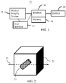
- Figure 1 shows one embodiment of a system 10 for visualization in medical imaging.
- the system 10 renders volume/surface hybrid models for medical visualization. Given the variation and subtly of structure in a patient volume, variance of tools or other objects modeled or detected in the patient, and lighting difficulties in the volume, the unified ray casting of the hybrid model allows for various effects appropriate for many different applications.
- the accuracy of projection rendering using ray casting of the scan volume benefits from combination with surface detection. Rather than limiting useful effects by separate surface rendering with rasterization, the same rays are used to detect the surface using an acceleration structure.
- the system 10 includes a medical imaging system 12, a user interface or input 14, a renderer 16, a memory 18, and a display 20. Additional, different, or fewer components may be provided. For example, a network or network connection is provided, such as for networking with a medical imaging network or data archival system. As another example, the user interface 14 is not provided.
- the user interface 14, renderer 16, memory 18, and display 20 are part of the medical imaging system 12.
- the user interface 14, renderer 16, memory 18, and/or display 20 are part of an archival and/or image processing system, such as associated with a medical records database workstation or server.
- the user interface 14, renderer 16, memory 18, and/or display 20 are a separate computer, such as desktop or laptop, a workstation, a server, a network, or combinations thereof.
- the user interface 14, renderer 16, memory 18, and display 20 may be parts of different systems, such as the memory 18 being in a picture archiving and communications system (PACS), the renderer 16 being part of a workstation, and/or the display 20 being an imaging system or radiological display.
- PACS picture archiving and communications system
- the system 10 is configured to implement the method of Figure 3 . Alternatively, other methods are implemented.
- the medical imaging system 12 is a CT, MR, ultrasound, x-ray, fluoroscopy, or emission tomography (i.e., functional imaging such as PET or SPECT) system.
- the medical imaging system 12 is any now known or later developed medical imaging system for scanning an interior of the patient.
- the medical imaging system 12 is configured by hardware, firmware, and/or software to scan the internal region of a patient and generate voxel data representing a scanned volume of the internal region.
- the medical imaging system 12 is configured to scan an internal region of the patient.
- the surface or skin of the patient may also be scanned or may not be scanned. Any portion or extent of the patient may be scanned, such as a scan of an organ, torso, extremity, or full body.
- the scan acquires data representing the interior of the patient.
- the represented portion includes a volume or three-dimensional distribution of response from the patient.
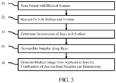
- Figure 2 shows an internal region 22 as a cube, but the scanned volume of the patient may have any shape.
- the medical imaging system 12 is configured to scan the patient to acquire at least one set of data.
- the set or frame of data represents the internal region of the patient at a specific time or period.
- a static volume is acquired.
- the scanning is repeated or performed in an ongoing manner to acquire a sequence of sets of voxel data.
- Each set represents the volume at a given time or period, so the sequence represents the volume over time (3D+t or 4D data).
- Any frame or volume rate may be provided.
- at least 10 volumes or sets of voxel data are acquired each second. Greater or lesser volume rates may be provided.
- the medical imaging system 12 acquires multiple volumes representing the same internal region or overlapping internal regions. Due to scanner or patient movement, comparison of scans from different times, or other medical specific variation, different sets of data may be acquired for rendering together. As another example, sets of voxel data from different scanning modalities (e.g., MR and ultrasound) are to be rendered together.
- scanning modalities e.g., MR and ultrasound
- the scan data may be output as a 3D reconstruction or data representing a volume.
- the acquired scan data is reconstructed to represent the volume.
- Fourier processing is applied to k-space data in MR to reconstruct the volume.
- computed tomography is used to reconstruct the volume (e.g., SPECT, or CT).
- data representing three dimensions in a scan format is interpolated to a regular or other grid, such as a Cartesian coordinate grid. Each datum is associated with a different volume location (voxel) in the patient volume and assigned a scalar intensity.
- the data from the scan is formatted as voxels in an isotropic grid.
- voxels in a 512x512x512 Cartesian grid are used.
- Anisotropic grids may be used.
- Other formats may be used, such as the data representing locations in a polar coordinate format.
- a scan response is provided by a scalar value (e.g., 16 bit dynamic range), but other representations may be used, such as RGB values.
- any one or more sets of voxel data representing intensity of return, density, attenuation, elasticity, motion, uptake, temperature, molecular spin response, other characteristics, or combinations thereof may be acquired by the medical imaging system 12.
- the memory 18 is a graphics processing memory, video random access memory, random access memory, system memory, cache memory, hard drive, optical media, magnetic media, flash drive, buffer, database, combinations thereof, or other now known or later developed memory device for storing the set or sets of voxel data and/or data representing one or more surfaces.
- the memory 18 is part of the medical imaging system 12, part of a computer associated with the renderer 16, part of a database, part of another system, or a standalone device.
- the memory 18 stores the hybrid volume/surface data.
- the medical scan data, surface, combined data set, reconstructions, rendering, and/or images are stored. Any data used for imaging or data in beginning, intermediate, or final stages of processing are stored for access by the renderer 16.
- the representation of the surface stored by the memory 18 is a two- or three-dimensional representation.
- Figure 2 shows a cylindrical surface 24.
- Surfaces of any shape may be provided, such as a surface modeling an organ, tool, or other object.
- the surface may have a flat, curved, or both flat and curved portions.
- the surface may be open or closed.
- the surface is a model representing an object not actually in the patient volume.
- the surface is a model representing an object in the patient volume.
- the surface is detected from the voxel data and separately quantified or modeled (e.g., a segmented, implicit, or iso-surface). For example, an inserted tool (e.g., catheter, endoscope, stent, or valve) existing within the patient is detected and the surface of the tool identified.
- an inserted tool e.g., catheter, endoscope, stent, or valve
- each voxel corresponding to the surfaces is flagged or used to define the surface.
- a mesh of connected nodes defines the surface.
- the nodes may be at or may be separate from the voxel locations.
- the surface may be based on a fit mathematical representation.
- the surface definition has a same or different resolution as the volume or voxel data.
- the location of the surface relative to the scanned volume is known or set. Where modeling is used, the location of the surface relative to the volume may be arbitrary or based on detected anatomical structure. Where segmentation of implicit structure is used to find the surface from the voxel data, the location relative to the volume is also determined. The location of the surface relative to the volume may be static or may change over time.
- more than one surface may be of interest.
- the surfaces are independent of each other, such as having no common or intersecting locations. Alternatively, the surfaces contact or intersect, but are separately defined. There may be one, two, three, or more surfaces for a given scan volume.
- the surface may be two-dimensional (2D)(e.g., a plane or selection region used as a visual guidance tool), three-dimensional (3D)(e.g., curved surface), 2D+time (2D+t), or 3d+t.
- Specialized algorithms for building the ray-surface intersection acceleration structure may be used for time-varying surface data during interactive rendering. Examples include GPU-based techniques for rapid reconstruction or techniques that allow for partial rebuilds. If only the location of the mesh is changed, the normal acceleration structure may be reused. For a time-varying surface, the acceleration structure may need to be rebuilt after each change using the GPU for interactive rendering.
- the memory 18 or other memory is a computer readable storage medium storing data representing instructions executable by the programmed renderer 16 for visualizing in medical imaging.
- the instructions for implementing the processes, methods, and/or techniques discussed herein are provided on computer-readable storage media or memories, such as a cache, buffer, RAM, removable media, hard drive, or other computer readable storage media.
- Computer readable storage media include various types of volatile and nonvolatile storage media.
- the functions, acts or tasks illustrated in the figures or described herein are executed in response to one or more sets of instructions stored in or on computer readable storage media.
- the functions, acts or tasks are independent of the particular type of instructions set, storage media, processor or processing strategy and may be performed by software, hardware, integrated circuits, firmware, micro code and the like, operating alone, or in combination.
- processing strategies may include multiprocessing, multitasking, parallel processing, and the like.
- the instructions are stored on a removable media device for reading by local or remote systems.
- the instructions are stored in a remote location for transfer through a computer network or over telephone lines.
- the instructions are stored within a given computer, CPU, GPU, or system.
- the user interface 14 is an input device with or without an output. Any input may be used, such as keyboard, button, slider, knob, track pad, mouse, track pad, or other sensor.
- the output may be on the display 20, an LED, light, or other output.
- the user interface 14 is configured to receive input from the user.
- the input may configure the rendering.
- the user inputs a value or values for any number of rendering parameters, such as view direction, type of lighting, visual effect, or transfer function.
- the user may interactively change one or more values of a setting.
- the user rotates or alters the view direction for rendering.
- the user selects the imaging application (e.g., heart imaging), resulting in loading of default settings.
- a processor or the renderer 16 uses default or determined values for one, more, or all of the settings.
- the rendering is performed again using the new setting.
- the interaction may appear more smooth or appealing to the user.
- the renderer 16 is a general processor, central processing unit, control processor, graphics processor, digital signal processor, three-dimensional rendering processor, image processor, application specific integrated circuit (ASIC), field programmable gate array (FPGA), digital circuit, analog circuit, combinations thereof, or other now known or later developed device for rendering an image from data.
- the renderer 16 is a single device or multiple devices operating in serial, parallel, or separately.
- the renderer 16 may be a main processor of a computer, such as a laptop or desktop computer, or may be a processor for handling some tasks in a larger system, such as in an imaging system.
- the renderer 16 is configured by hardware, firmware, and/or software.
- the renderer 16 is a graphics processing unit (GPU) or a graphics card with rendering code.
- a GPU is a massively parallel computation device.
- CUDA or OpenCL languages are used to program the GPU.
- the x86-based Xeon Phi or custom FPGA/ASIC implementations are used.
- One side effect of the ray-tracing pipeline is that the computations are generally performed per pixel in screen space, allowing for efficient scaling with multiple computational devices.
- Multiple GPUs in a render node, GPU clusters, CPU/GPU hybrid systems, or other computational architectures may be used. Sample-based, tile-based, or frame-based distribution of the rendering may be used.
- the renderer 16 is configured to generate an image as a function of the hybrid volume/surface data.
- the image is a single representation of the patient volume and surfaces using both types of data.
- more than one or more than two representations of the patients may be provided, such as a rendering multi-planar reconstruction images from the scan data.
- the renderer 16 is configured to cast rays through the volume.
- a ray is cast for each pixel of the image.
- Figure 2 shows an example viewing ray 26 cast through the volume 22 and passing by the surface 24. Other rays 26 at other positions intersect the surface 24.
- the rays 26 are cast as part of a camera or lens model.
- Traditional parallel or perspective projections may be used.
- the rays 26 are cast as parallel from pixel locations or diverging with an origin at a virtual viewer of the volume. The viewer may be positioned outside or inside the volume 22.
- More complex non-linear projections may be used, such as to model a medical scope (e.g., endoscope or fiber optic viewer).
- non-linear projections include rays 26 cast to model a fisheye, spherical, or cylindrical lens.
- the rays 26 are cast with different geometry than parallel or diverging from a single point.
- the camera and corresponding rays may be modeled as a 360-degree camera for a cylindrical view from inside a volume.
- Non-linear projections may be difficult to render with rasterization.
- the ray-tracing pipeline may better simulate the complex optics of an endoscope or other medical device for use in computer-augmented procedures.
- the model and corresponding rays may be cast to represent a non-flat display, such as for curved displays or virtual/augmented reality.
- the rays 26 are defined relative to the volume 22 for rendering. Since the location of the surface is known relative to the volume 22, the same rays 26 may be used for both the projection integration from the voxels as well as for surface identification. Rather than separately rendering the surface, the rays 26 already cast for projection rendering are used to check for the surface and account for surface interaction with the voxels. While or in parallel with integration along each ray, the intersections of any surfaces with that ray are identified. For example, the integration of voxels begins at one location and progresses along the ray. At each voxel being added to the accumulation of samples, a check is made for the intersection. As another example, the check for the intersection anywhere along the ray 26 is performed using the same ray 26 but occurs prior to or at the start of integration along the ray 26. The same rays 26 are used for both the integration and the check.
- the renderer 16 is configured to integrate along the rays 26 using the voxel data. Starting from where the ray 26 enters the volume 22 or from where the ray 26 exits the volume 22, integration is performed along the ray 26 using any intersecting voxels. Since the voxels may not be centered along the ray, interpolation may be used to determine a value along the ray based on surrounding voxels. Any form of integration may be used, as defined by the transfer function. Opacity weighted summation or averaging, minimum or maximum selection, alpha blending, or other integration is provided to determine a scalar or other value for the pixel represented by the ray 26.
- ray tracing accumulates samples (e.g., voxel values) from the volumetric data using application-specific interpolation and/or transfer functions.
- samples e.g., voxel values
- transfer functions There are many medical applications. Different types of imaging modalities use different interpolation and/or transfer functions. Within a same modality, different types of scanning may use different interpolation and/or transfer functions. Within a same modality and same type of scanning, different interpolation and/or transfer functions may be used for different users, different organs, different types of diagnoses, different clinical workflows, or other medically relevant reasons. Any now known or later developed interpolation and/or transfer function for integrating (e.g., accumulating samples) along the rays 26 may be used.
- the integration may include voxel data representing the same locations from more than one set of data. For example, a location or overlapping region in one set of data is represented by another set of data as well.
- the integration combines the interpolated samples from both sets to render an image responsive to both sets. The combination occurs for any overlapping locations.
- the renderer 16 is configured to check for the three-dimensional surface along the rays while integrating.
- the check is performed as an initial operation at the beginning of the integrating or at each depth along the ray during the integrating.
- the rays 26 may or may not intersect the surface or surfaces.
- the check is for intersection with one or more surfaces. Intersections of the ray 26 with all of the surfaces are detected.
- the check is whether the ray intersects each part of each surface.
- a more rapid check is performed by checking the ray 26 relative to an acceleration structure.
- the surface is modeled at different levels of resolution, such as hierarchal cubes. By checking for intersection with the lowest resolution or root cube, it is determined whether the ray intersects the surface at all with a simple comparison. If intersecting, higher resolution or different hierarchy of the acceleration structure is checked to identify where on the surface the ray 26 intersects the surface 24. More than one intersection with a given surface may be identified.
- the acceleration structure may accelerate or more efficiently check for intersection.
- the acceleration structure may more likely allow for real-time or interactive rendering. Any now known or later developed acceleration structures for computing ray intersections with the surfaces in a real-time or interactive environment may be used.
- Different visualization requirements e.g., 4D visualization with animated surfaces vs. 3D visualization with static surfaces and/or mesh size
- the capabilities of the underlying computational architecture i.e., the renderer 16
- a Bounded Volume Hierarchies (BVH) or Kd-trees are used for 4D imaging.
- a TRBVH or SBVH acceleration structures are used.
- the renderer 16 is configured to alter contribution of the voxel data along the rays 26 in the integrating based on detection of the surface or surfaces along the rays 26. Where a ray intersects a surface, the surface is modeled as altering the contribution of the voxels along the entire ray 26, just for voxels within a range of the surface, or for voxels on one side of the surface. For example, the samples accumulated after detection of the surface are altered.
- the contribution being altered is of magnitude of the voxel scalar, color, opacity, lighting, transfer function, interpolation function, or other characteristic. Any aspect of the rendering may be altered to account for the surface in the rendered volume.
- the intersection points may provide opacity weighted scalar values to be included in the integration, such as opacity weighted scalar values defined by a texture of the surface. Alternatively or additionally, the intersection is used to alter characteristics of the voxels being integrated from the volume. Any combination of the intersection points and volume integration to model the interaction between the surface and the volume may be used.
- intersection points and the volume integration data along the viewing rays are combined using application-specific techniques.
- the alteration of the contribution may depend on the medical imaging application. For different modalities, types of scans, user preferences, organ of interest, diagnosis, and/or workflows, different types of contributions are provided.
- the unified surface/volume ray tracing pipeline implements one or more of a number of effects that are difficult to achieve with traditional rasterization or traditional volume rendering systems.
- the contribution of the voxels is altered to represent or show the surface as transparent with a color or tint.
- the surface level of transparency is used to further opacity weight voxels beyond the surface from the virtual viewer.
- the surface results in the opacity of the voxels being more transparent than as indicated for the voxels without the surface.
- the surface color is used to tint or change the hue represented by the voxels beyond the surface from the virtual viewer.
- illumination effects are modeled using the intersection points and integration.
- the alteration of the light contribution accounts for ambient occlusions.
- Ambient occlusions provide strong visual cues for the spatial relationships in the data. By adding shadowing due to ambient light, a viewer may better understand the spatial relationship between rendered structures, including between the surface and the implicit structures of the volume. Accurate interplay between the occlusions generated by the mesh surfaces and the volumetric data are provided. Any ambient occlusion model may be used. The ambient occlusion model accounts for shadowing of voxels given the intersection point. The effect or amount of ambient light for a given voxel is determined.
- the surface alters the amount of ambient light, so the ambient light contribution in the form of color, transparency, and/or intensity for voxels near the surface is altered to account for the surface.
- reflections, light refraction, attenuation, and/or material or tissue property effects caused by the surface or intersection point relative to the volume are modeled.
- the modeling alters the contribution of the voxels to the integration.
- the contribution is altered for shadowing caused by the surface.
- the surface may cause shadowing for direct light sources. Shadowing provides strong depth cues when combined with dynamic lighting.
- the intensity e.g., magnitude of the scalar
- the shadow model may determine which of the voxels are shadowed and by how much, so which of the voxels have their contribution altered.
- the contribution of the voxels to the integration is altered based on light transport simulation effects.
- Light transport through the surface is modeled to determine the alteration of the contribution due to the surface.
- photorealistic rendering of the surface/volume data is performed using light transport simulations. Any light transport simulation may be used, such as path tracing, photon mapping, or Monte Carlo ray tracing. The light transport simulation is different for some voxels than for others due to the intersection with the surface.
- Light simulation techniques further improve the understanding of spatial relationships, compared to ambient occlusions alone, through global illumination effects, such as color bleeding.
- the interplay of light between the mesh surfaces and the volumetric data may be rapidly and accurately modeled.
- Various medical imaging applications may benefit.
- modeling an inserted object or tool as a light source may benefit diagnosis.
- the shadowing, ambient occlusions, and/or other illumination models may cause structure closer to the surface to be brighter or more visible with finer detail. Treating the surface as partially transparent may allow for visualization of a greater amount of anatomy while providing the reviewer with information on placement of the surface.
- the contribution may be altered to account for more than one surface and/or more than one intersection with a surface along a ray. Detection of each of the three-dimensional surfaces or intersections is used to alter the contribution. For example, greater shadowing and/or ambient occlusion occur for voxels associated with viewing through a greater number of surfaces.
- the accurate visualization of multiple transparent surfaces remains a challenge for rasterization-based rendering pipelines. Although a number of complex techniques exist, their integration with volume rendering is not straightforward and in some cases not even possible. Using ray tracing for both surface and volume rendering allows for accurate simulation of transparency. Applications include surgical planning and blood vessel or organ visualization.
- the casting of rays, integration along the rays, checking for surface intersections with the rays, and altering the contributions to the integration based on identified intersections is repeated.
- the rendering is repeated.
- the rendering is repeated with a previous set of voxels or with a newly acquired set. The repetition is performed over time by the renderer 16, so may occur at a high rate.
- the rendering rate may be maintained using variable-resolution rendering and/or accumulation of multiple rendering passes with immediate visual feedback.
- Sample reconstruction and/or frameless rendering may decouple the renderer 16 from the display 20.
- the renderer 16 generates an image or sequence of images representing the internal region of the patient.
- a given image represents the internal region at a specific time or period.
- the sequence of images may be for a static volume with different rendering settings or for real-time imaging over time.
- the generated images are scalar values or display color values (e.g., RGB) for pixels of the images.
- the images are output by transfer or loading into a display buffer, configuring the display 20.
- the display 20 is configured to display the image.
- the display 20 is a monitor, LCD, projector, plasma display, CRT, printer, or other now known or later developed devise for outputting visual information.
- the display 20 is configured by receiving images, graphics, or other information from the renderer 16, memory 18, or medical imaging system 12.
- the display 20 receives the image rendered from the hybrid volume and surface model by the renderer 16.
- the image is output to the user.
- the image includes a projection rendering of the volume with effects from the surface.
- the image output by the renderer 16 is based on the integration with contribution altered by the surface or surfaces.
- the image represents the internal region of the patient.
- the image changes over time, such as due to user interaction or on-going acquisition of medical scan data.
- the user positions a clipping plane or planes so that different parts of the patient volume are masked.
- the rendering shows the internal region from the scan data not clipped or that intersects the clipping plane.
- One rendered image is replaced with another rendered image based on the change in the rendering parameter, such as the view direction or clipping plane position.
- a sequence of images is displayed. The sequence is based on repetition of the integration as additional sets of voxel data are acquired.
- Figure 3 shows a method for visualization of a patient in medical imaging.
- Ray casting is used to render an image from volume information and one more surfaces. Rather than rendering the surface through rasterization, the same ray casting is used to locate the surface relative to the volume being rendered and to alter the projection rendering to account for the surface and surface characteristics.
- This unified ray casting approach may allow for efficient or real-time modeling of various effects of the surface relative to the volume.
- act 30 is performed by a medical scanner, and acts 32-38 are performed by a renderer. Any one or more of the acts may be performed by different devices.
- acts 34 and 36 are performed in the order shown, a reverse order, or simultaneously.
- Act 38 may be performed as part of act 36.
- an image is not generated on a display in act 38, but instead the image is saved or transferred.
- user input is provided for interacting with the rendering.
- the method is performed once to generate an image.
- the method is repeated in real-time with an on-going acquisition in medical imaging, such as imaging moving anatomy.
- Repetition may be provided for interactive rendering and/or representing an object moving in the patient.
- Acts 34-38 are repeated in real-time with acquisition of addition samples, alteration of rendering, change in the surface model, or combinations thereof. For the discussion below of the acts of Figure 3 , a real-time acquisition and rendering is used.
- a medical scanner acquires a sequence of sets of voxels.
- the sequence represents a volume of the patient over time.
- a patient is scanned with a medical imaging scanner.
- the interior of the patient is scanned, such as with MR, x-ray (e.g., CT), or emission tomography (e.g., PET or SPECT).
- the scan is performed in any format, such as detecting emissions along lines of response, acquiring k-space data at magnetic gradient defined locations, or acquiring projections through the patient with x-rays from different directions.
- NxMxO region is acquired, where N, M, and O are integers greater than 1.
- a processor such as the renderer, or the medical imaging system reconstructs a sequence of volumes representing, at least in part, the internal portion of the patient. Any reconstruction from the scan data may be used. The reconstruction repetitively determines scalar or other values for each of a plurality of voxels distributed in three dimensions.
- a predefined surface or a surface extracted from the volumes is identified.
- the surface is a mesh, segmentation, or other representation of a specific surface rather than an implicit surface.
- the surface may be a virtual object to be placed in the volume, a model of an actual object to be placed in the patient, or a segmented structure determined from the scan data.
- rays are cast through the voxels and surface.
- the ray casting is performed using any camera model, such as a non-linear model.
- the rays are cast to project the three-dimensional space to a two-dimensional collection of pixels.
- the ray casting indicates the spatial locations of the rays.
- the ray casting is performed for each of the periods or times for which a set of voxel data is provided. For each time, the rays are cast. Alternatively, the cast rays are repetitively used for different sets over time.
- intersections of the rays with one or more surfaces are determined. Each ray projected through the volume intersects none, one, or more surfaces. The depths or locations of the intersections are determined.
- an acceleration structure is used to determine the intersections. Any search strategy, such as hierarchal cubes, may be used to reduce the processing to locate intersections.
- the acceleration structure is traversed using the rays in parallel with the integrating in act 36 along the rays. By traversing the acceleration structure, the intersections are found. Intersections of the rays for a given volume (i.e., given time or period) with one or more surfaces are determined. The intersections are determined for each of the times or periods or are reused for different times or periods where the surface stays in a same position.
- samples are accumulated from the volumetric data.
- the volumetric data is voxels of scalar, color, and/or transparency values representing the patient along the rays.
- the voxels are samples. These samples are accumulated by integration or other projection rendering (e.g., minimum or maximum selection). In one embodiment, the integration or accumulation is performed based on application specific interpolation and transfer functions. The voxels along each ray are combined to determine a pixel value for that ray.
- the accumulation of the samples varies based on the intersections. Using the surface characteristics, the intersections define voxel locations where effects occur. The lighting or other effects representing interaction of the surface with the volume determine the variation in the accumulation. One or more aspects or contributions of the samples to the accumulation changes based on the effect or effects. For example, the magnitude of some of the samples, color of some of the samples, opacity of some of the samples, lighting, function for integrating, or combinations thereof is varied based on the intersection.
- the application-specific model may determine which of the samples are varied and in what way. Accumulation of some samples may not vary, such as for samples spaced from the surface or on one side of the surface relative to the virtual viewer.
- the accumulation is repeated for each of the rays to form an image.
- the integration of voxels along the rays is repeated for each of the times or periods, providing projection information over time.
- one or more medical images are generated.
- the accumulated samples are used to generate the medical image or images, such as a sequence of rendered images from integrated voxels along the rays. Since the contribution of some samples is altered based any intersections with the surface or surfaces, the images include effects modeled from the interaction of the surface with the volume. Since ray casting is used, more accurate rendering of the volume for medical diagnosis as compared to rasterization is provided. By using unified ray casting, the surface effects may be quickly created by detecting the intersections and using the intersections to alter contribution in accumulation.
- the rendered image or images are displayed by the renderer 16 on the display 20.
- the image represents the patient and a surface or surfaces in the patient.
- a photorealistic or nonrealistic representation of the surface interaction with the volume is provided in combination with a medical scan representation of at least part of an interior of the patient.
Landscapes
- Engineering & Computer Science (AREA)
- Computer Graphics (AREA)
- Physics & Mathematics (AREA)
- General Physics & Mathematics (AREA)
- Theoretical Computer Science (AREA)
- Image Generation (AREA)
- Apparatus For Radiation Diagnosis (AREA)
- Magnetic Resonance Imaging Apparatus (AREA)
Claims (12)
- Ein System zur Visualisierung in der medizinischen Bildgebung, wobei das System Folgendes umfasst:ein medizinisches Bildgebungssystem (12), das so konfiguriert ist, dass es einen inneren Bereich eines Patienten abtastet und Voxeldaten erzeugt, die ein Volumen (22) darstellen, das den inneren Bereich umfasst;einen Speicher (18), der so konfiguriert ist, dass er eine dreidimensionale Oberfläche (24) eines Modells eines Objekts innerhalb des Volumens (22) speichert, wobei die dreidimensionale Oberfläche des Modells einen Transparenzgrad aufweist und getrennt von den Voxeldaten, die das Volumen darstellen, und mit einer bekannten räumlichen Beziehung zu diesen modelliert ist;einen Renderer (16), der so konfiguriert ist, dass er Strahlen durch das Volumen (22) projiziert, entlang der Strahlen unter Verwendung der Voxeldaten integriert, entlang derselben Strahlen auf die dreidimensionale Oberfläche (24) hin prüft, während er unter Verwendung der bekannten räumlichen Beziehung integriert, und den Beitrag zur Integration der Voxeldaten jenseits der Oberfläche von einem virtuellen Betrachter entlang eines oder mehrerer der Strahlen auf der Grundlage der Erkennung der dreidimensionalen Oberfläche (24) entlang des einen oder mehrerer der Strahlen ändert; undeine Anzeige (20), die so konfiguriert ist, dass sie ein von dem Renderer (16) ausgegebenes gerendertes Bild anzeigt, wobei das gerenderte Bild den internen Bereich darstellt.
- Das System nach Anspruch 1, wobei das medizinische Bildgebungssystem (12) so konfiguriert ist, dass es wiederholt scannt, so dass eine Sequenz von Sätzen von Voxeldaten bereitgestellt wird, wobei der Renderer (16) so konfiguriert ist, dass er Strahlen projiziert, integriert, prüft und für jeden der Sätze der Sequenz ändert, und wobei die Anzeige so konfiguriert ist, dass sie das Bild als eines in einer Sequenz von Bildern basierend auf der Wiederholung beim Integrieren anzeigt.
- Das System nach Anspruch 1, umfassend ferner eine Benutzerschnittstelle, die so konfiguriert ist, dass sie Eingaben zum Ändern eines Rendering-Parameters empfängt, wobei der Renderer (16) so konfiguriert ist, dass er aus den Voxeldaten unter Verwendung des geänderten Rendering-Parameters rendert, und wobei das gerenderte Bild basierend auf dem Rendering unter Verwendung des geänderten Rendering-Parameters ersetzt wird.
- Das System nach Anspruch 1, wobei der Renderer (16) so konfiguriert ist, dass er unter Verwendung einer Beschleunigungsstruktur prüft.
- Das System nach Anspruch 4, wobei die Beschleunigungsstruktur so konfiguriert ist, dass sie mit Echtzeit- oder interaktivem Rendering arbeitet.
- Das System nach Anspruch 1, wobei die dreidimensionale Oberfläche (24) ein Netz umfasst.
- Das System nach Anspruch 1, wobei die dreidimensionale Oberfläche (24) eine Vielzahl von dreidimensionalen Oberflächen (24) innerhalb des Volumens (22) umfasst, und wobei der Renderer (16) so konfiguriert ist, dass er auf alle dreidimensionalen Oberflächen (24) prüft und den Beitrag basierend auf der Erkennung jeder der dreidimensionalen Oberflächen (24) ändert.
- Das System nach Anspruch 1, wobei das medizinische Bildgebungssystem (12) so konfiguriert ist, dass es verschiedene Sätze von Voxeldaten erfasst, die das Volumen (22) darstellen, und wobei der Renderer (16) so konfiguriert ist, dass er aus den Voxeldaten, die dieselben Orte darstellen, aus den verschiedenen Sätzen integriert.
- Das System nach Anspruch 1, wobei der Renderer (16) so konfiguriert ist, dass er den Beitrag ändert, um die Oberfläche (24) als transparent mit Farbe darzustellen.
- Das System nach Anspruch 1, wobei der Renderer (16) so konfiguriert ist, dass er den Beitrag zur Umgebungsokklusion ändert.
- Das System nach Anspruch 1, wobei der Renderer (16) so konfiguriert ist, dass er den Beitrag zur Abschattung durch die Oberfläche (24) ändert.
- Das System nach Anspruch 1, wobei der Renderer (16) so konfiguriert ist, dass er die Strahlen als nichtlineare Projektionen für ein medizinisches Endoskop erzeugt.
Applications Claiming Priority (1)
| Application Number | Priority Date | Filing Date | Title |
|---|---|---|---|
| PCT/US2015/048215 WO2017039664A1 (en) | 2015-09-03 | 2015-09-03 | Visualization of surface-volume hybrid models in medical imaging |
Publications (3)
| Publication Number | Publication Date |
|---|---|
| EP3345162A1 EP3345162A1 (de) | 2018-07-11 |
| EP3345162B1 true EP3345162B1 (de) | 2022-08-24 |
| EP3345162B9 EP3345162B9 (de) | 2022-11-16 |
Family
ID=54140705
Family Applications (1)
| Application Number | Title | Priority Date | Filing Date |
|---|---|---|---|
| EP15763757.0A Active EP3345162B9 (de) | 2015-09-03 | 2015-09-03 | Visualisierung von oberflächenvolumenhybridmodellen in der medizinischen bildgebung |
Country Status (4)
| Country | Link |
|---|---|
| US (1) | US10565774B2 (de) |
| EP (1) | EP3345162B9 (de) |
| CN (1) | CN107924580B (de) |
| WO (1) | WO2017039664A1 (de) |
Families Citing this family (21)
| Publication number | Priority date | Publication date | Assignee | Title |
|---|---|---|---|---|
| WO2018046440A1 (en) * | 2016-09-06 | 2018-03-15 | Eidgenoessische Technische Hochschule Zurich (Ethz) | Ray-tracing methods for realistic interactive ultrasound simulation |
| US10607735B2 (en) | 2016-09-06 | 2020-03-31 | International Business Machines Corporation | Hybrid rendering system for medical imaging applications |
| US10311631B2 (en) * | 2017-05-12 | 2019-06-04 | Siemens Healthcare Gmbh | Light path fusion for rendering surface and volume data in medical imaging |
| US10918441B2 (en) * | 2017-11-22 | 2021-02-16 | Canon U.S.A., Inc. | Devices, systems, and methods for ablation-zone simulation and visualization |
| US10751128B2 (en) * | 2017-11-22 | 2020-08-25 | Canon U.S.A., Inc. | Devices, systems, and methods for ablation-zone simulation and visualization |
| US10665007B2 (en) * | 2018-01-15 | 2020-05-26 | Siemens Healthcare Gmbh | Hybrid interactive mode for rendering medical images with ray tracing |
| US10740952B2 (en) * | 2018-08-10 | 2020-08-11 | Nvidia Corporation | Method for handling of out-of-order opaque and alpha ray/primitive intersections |
| US11191525B2 (en) * | 2018-08-10 | 2021-12-07 | General Electric Company | Method and system for visualizing overlapping images |
| US10832466B2 (en) | 2018-10-25 | 2020-11-10 | International Business Machines Corporation | View-dependent stochastic volume rendering with Monte Carlo ray exploration |
| EP3667624A1 (de) * | 2018-12-14 | 2020-06-17 | Siemens Healthcare GmbH | Verfahren zur bestimmung der beleuchtungsauswirkung eines volumetrischen datensatzes |
| CN110276823B (zh) * | 2019-05-24 | 2023-04-07 | 中国人民解放军陆军装甲兵学院 | 基于光线追踪且实时可交互的集成成像生成方法及系统 |
| US11120611B2 (en) * | 2019-08-22 | 2021-09-14 | Microsoft Technology Licensing, Llc | Using bounding volume representations for raytracing dynamic units within a virtual space |
| EP3796265A1 (de) * | 2019-09-23 | 2021-03-24 | Siemens Healthcare GmbH | Implizite oberflächenschattierung in der medizinischen volumetrischen wiedergabe |
| WO2021081278A1 (en) * | 2019-10-25 | 2021-04-29 | Hyperfine Research, Inc. | Systems and methods for generating three-dimensional medical images using ray tracing |
| EP3879498B1 (de) | 2020-03-09 | 2025-05-21 | Siemens Healthineers AG | Verfahren zum rendern eines volumens und einer in dem volumen eingebetteten oberfläche |
| US11443476B2 (en) * | 2020-05-27 | 2022-09-13 | Canon Medical Systems Corporation | Image data processing method and apparatus |
| EP4231246A1 (de) | 2022-02-16 | 2023-08-23 | Siemens Healthcare GmbH | Verfahren zur optischen führung während eines chirurgischen eingriffs |
| US12254570B2 (en) * | 2022-05-03 | 2025-03-18 | Adobe Inc. | Generating three-dimensional representations for digital objects utilizing mesh-based thin volumes |
| EP4273811B1 (de) | 2022-05-06 | 2026-03-04 | Siemens Healthineers AG | Technik zur optimierung der wiedergabeparameter von überlagerungen medizinischer bilder |
| CN114937049A (zh) * | 2022-05-31 | 2022-08-23 | 上海联影医疗科技股份有限公司 | 图像的裁切方法及裁切系统 |
| CN119295680B (zh) * | 2024-12-12 | 2025-04-18 | 中国标准化研究院 | 一种基于虚拟现实的工业数据可视化方法及系统 |
Family Cites Families (16)
| Publication number | Priority date | Publication date | Assignee | Title |
|---|---|---|---|---|
| US6608717B1 (en) * | 1999-01-29 | 2003-08-19 | Colorado State University Research Foundation | Optical coherence microscope and methods of use for rapid in vivo three-dimensional visualization of biological function |
| US7659894B2 (en) * | 2000-06-19 | 2010-02-09 | Mental Images Gmbh | Terminating spatial partition hierarchies by a priori bounding memory |
| US7085406B2 (en) * | 2001-07-27 | 2006-08-01 | General Electric Company | Method and system for unsupervised transfer function generation for images of rendered volumes |
| CN101219058B (zh) * | 2002-03-14 | 2012-01-11 | Netkisr有限公司 | 分析和显示计算机体层摄影术数据的系统和方法 |
| US20090063110A1 (en) * | 2003-03-14 | 2009-03-05 | Transpire,Inc. | Brachytherapy dose computation system and method |
| US8600125B2 (en) * | 2005-06-22 | 2013-12-03 | The Research Foundation Of State University Of New York | System and method for computer aided polyp detection |
| US7379062B2 (en) * | 2005-08-01 | 2008-05-27 | Barco Nv | Method for determining a path along a biological object with a lumen |
| CN101021537A (zh) * | 2007-01-04 | 2007-08-22 | 山东师范大学 | 检测细胞羟基自由基的荧光探针及合成方法和用途 |
| US8411087B2 (en) * | 2008-02-28 | 2013-04-02 | Microsoft Corporation | Non-linear beam tracing for computer graphics |
| US20110090222A1 (en) * | 2009-10-15 | 2011-04-21 | Siemens Corporation | Visualization of scaring on cardiac surface |
| CN102613990B (zh) * | 2012-02-03 | 2014-07-16 | 声泰特(成都)科技有限公司 | 三维超声频谱多普勒的血流速度及其空间分布显示方法 |
| US20130328874A1 (en) | 2012-06-06 | 2013-12-12 | Siemens Medical Solutions Usa, Inc. | Clip Surface for Volume Rendering in Three-Dimensional Medical Imaging |
| US20140125653A1 (en) * | 2012-11-06 | 2014-05-08 | Biosense Webster (Israel), Ltd. | Combining three-dimensional surfaces |
| GB2550091B (en) * | 2013-03-15 | 2018-04-04 | Imagination Tech Ltd | Rendering with point sampling and pre-computed light transport information |
| US9842424B2 (en) * | 2014-02-10 | 2017-12-12 | Pixar | Volume rendering using adaptive buckets |
| US10200627B2 (en) * | 2014-04-09 | 2019-02-05 | Imagination Technologies Limited | Virtual camera for 3-D modeling applications |
-
2015
- 2015-03-09 US US15/750,296 patent/US10565774B2/en active Active
- 2015-09-03 WO PCT/US2015/048215 patent/WO2017039664A1/en not_active Ceased
- 2015-09-03 CN CN201580082840.XA patent/CN107924580B/zh active Active
- 2015-09-03 EP EP15763757.0A patent/EP3345162B9/de active Active
Also Published As
| Publication number | Publication date |
|---|---|
| US10565774B2 (en) | 2020-02-18 |
| EP3345162B9 (de) | 2022-11-16 |
| WO2017039664A1 (en) | 2017-03-09 |
| US20180225862A1 (en) | 2018-08-09 |
| CN107924580A (zh) | 2018-04-17 |
| EP3345162A1 (de) | 2018-07-11 |
| CN107924580B (zh) | 2021-04-23 |
Similar Documents
| Publication | Publication Date | Title |
|---|---|---|
| EP3345162B1 (de) | Visualisierung von oberflächenvolumenhybridmodellen in der medizinischen bildgebung | |
| EP3401878B1 (de) | Lichtpfadfusion zum rendering von oberflächen- und volumendaten in der medizinischen bildgebung | |
| EP3493161B1 (de) | Übertragungsfunktionsbestimmung in der medizinischen bildgebung | |
| JP6373600B2 (ja) | 医用画像処理装置及び医用画像処理方法 | |
| CA2973449C (en) | Method, device and system for simulating shadow images | |
| US10755474B1 (en) | Method of processing a volumetric dataset and a method of rendering a volumetric dataset | |
| EP3404621B1 (de) | Innenbeleuchtung für endoskopische organvisualisierung | |
| US20210090325A1 (en) | Implicit surface shading in medical volumetric rendering | |
| US12475633B2 (en) | Technique for real-time rendering of medical images using virtual spherical light sources | |
| Drouin et al. | PRISM: An open source framework for the interactive design of GPU volume rendering shaders | |
| US12002147B2 (en) | Method and system for optimizing distance estimation | |
| US9875569B2 (en) | Unified 3D volume rendering and maximum intensity projection viewing based on physically based rendering | |
| Kalarat et al. | Real-time volume rendering interaction in virtual reality | |
| Zhang et al. | Medical image volumetric visualization: Algorithms, pipelines, and surgical applications | |
| Bindu | Numerical integration techniques for volume rendering | |
| Diepenbrock | Rapid development of applications for the interactive visual analysis of multimodal medical data | |
| Wei et al. | A software platform for interactive analysis on 3D medical data | |
| Anthony et al. | Interactive Surface Rending for Medical Visualization |
Legal Events
| Date | Code | Title | Description |
|---|---|---|---|
| STAA | Information on the status of an ep patent application or granted ep patent |
Free format text: STATUS: THE INTERNATIONAL PUBLICATION HAS BEEN MADE |
|
| PUAI | Public reference made under article 153(3) epc to a published international application that has entered the european phase |
Free format text: ORIGINAL CODE: 0009012 |
|
| STAA | Information on the status of an ep patent application or granted ep patent |
Free format text: STATUS: REQUEST FOR EXAMINATION WAS MADE |
|
| 17P | Request for examination filed |
Effective date: 20180301 |
|
| AK | Designated contracting states |
Kind code of ref document: A1 Designated state(s): AL AT BE BG CH CY CZ DE DK EE ES FI FR GB GR HR HU IE IS IT LI LT LU LV MC MK MT NL NO PL PT RO RS SE SI SK SM TR |
|
| AX | Request for extension of the european patent |
Extension state: BA ME |
|
| DAV | Request for validation of the european patent (deleted) | ||
| DAX | Request for extension of the european patent (deleted) | ||
| STAA | Information on the status of an ep patent application or granted ep patent |
Free format text: STATUS: EXAMINATION IS IN PROGRESS |
|
| 17Q | First examination report despatched |
Effective date: 20200828 |
|
| REG | Reference to a national code |
Ref country code: DE Ref legal event code: R079 Ref document number: 602015080473 Country of ref document: DE Free format text: PREVIOUS MAIN CLASS: G06T0015080000 Ipc: G06T0015060000 |
|
| GRAP | Despatch of communication of intention to grant a patent |
Free format text: ORIGINAL CODE: EPIDOSNIGR1 |
|
| STAA | Information on the status of an ep patent application or granted ep patent |
Free format text: STATUS: GRANT OF PATENT IS INTENDED |
|
| RIC1 | Information provided on ipc code assigned before grant |
Ipc: G06T 15/06 20110101AFI20220210BHEP |
|
| INTG | Intention to grant announced |
Effective date: 20220316 |
|
| GRAS | Grant fee paid |
Free format text: ORIGINAL CODE: EPIDOSNIGR3 |
|
| GRAA | (expected) grant |
Free format text: ORIGINAL CODE: 0009210 |
|
| STAA | Information on the status of an ep patent application or granted ep patent |
Free format text: STATUS: THE PATENT HAS BEEN GRANTED |
|
| AK | Designated contracting states |
Kind code of ref document: B1 Designated state(s): AL AT BE BG CH CY CZ DE DK EE ES FI FR GB GR HR HU IE IS IT LI LT LU LV MC MK MT NL NO PL PT RO RS SE SI SK SM TR |
|
| REG | Reference to a national code |
Ref country code: CH Ref legal event code: EP |
|
| REG | Reference to a national code |
Ref country code: IE Ref legal event code: FG4D |
|
| REG | Reference to a national code |
Ref country code: AT Ref legal event code: REF Ref document number: 1514187 Country of ref document: AT Kind code of ref document: T Effective date: 20220915 Ref country code: DE Ref legal event code: R096 Ref document number: 602015080473 Country of ref document: DE |
|
| REG | Reference to a national code |
Ref country code: CH Ref legal event code: PK Free format text: BERICHTIGUNG B9 |
|
| REG | Reference to a national code |
Ref country code: LT Ref legal event code: MG9D |
|
| REG | Reference to a national code |
Ref country code: NL Ref legal event code: MP Effective date: 20220824 |
|
| PG25 | Lapsed in a contracting state [announced via postgrant information from national office to epo] |
Ref country code: SE Free format text: LAPSE BECAUSE OF FAILURE TO SUBMIT A TRANSLATION OF THE DESCRIPTION OR TO PAY THE FEE WITHIN THE PRESCRIBED TIME-LIMIT Effective date: 20220824 Ref country code: RS Free format text: LAPSE BECAUSE OF FAILURE TO SUBMIT A TRANSLATION OF THE DESCRIPTION OR TO PAY THE FEE WITHIN THE PRESCRIBED TIME-LIMIT Effective date: 20220824 Ref country code: PT Free format text: LAPSE BECAUSE OF FAILURE TO SUBMIT A TRANSLATION OF THE DESCRIPTION OR TO PAY THE FEE WITHIN THE PRESCRIBED TIME-LIMIT Effective date: 20221226 Ref country code: NO Free format text: LAPSE BECAUSE OF FAILURE TO SUBMIT A TRANSLATION OF THE DESCRIPTION OR TO PAY THE FEE WITHIN THE PRESCRIBED TIME-LIMIT Effective date: 20221124 Ref country code: NL Free format text: LAPSE BECAUSE OF FAILURE TO SUBMIT A TRANSLATION OF THE DESCRIPTION OR TO PAY THE FEE WITHIN THE PRESCRIBED TIME-LIMIT Effective date: 20220824 Ref country code: LV Free format text: LAPSE BECAUSE OF FAILURE TO SUBMIT A TRANSLATION OF THE DESCRIPTION OR TO PAY THE FEE WITHIN THE PRESCRIBED TIME-LIMIT Effective date: 20220824 Ref country code: LT Free format text: LAPSE BECAUSE OF FAILURE TO SUBMIT A TRANSLATION OF THE DESCRIPTION OR TO PAY THE FEE WITHIN THE PRESCRIBED TIME-LIMIT Effective date: 20220824 Ref country code: FI Free format text: LAPSE BECAUSE OF FAILURE TO SUBMIT A TRANSLATION OF THE DESCRIPTION OR TO PAY THE FEE WITHIN THE PRESCRIBED TIME-LIMIT Effective date: 20220824 |
|
| REG | Reference to a national code |
Ref country code: AT Ref legal event code: MK05 Ref document number: 1514187 Country of ref document: AT Kind code of ref document: T Effective date: 20220824 |
|
| PG25 | Lapsed in a contracting state [announced via postgrant information from national office to epo] |
Ref country code: PL Free format text: LAPSE BECAUSE OF FAILURE TO SUBMIT A TRANSLATION OF THE DESCRIPTION OR TO PAY THE FEE WITHIN THE PRESCRIBED TIME-LIMIT Effective date: 20220824 Ref country code: IS Free format text: LAPSE BECAUSE OF FAILURE TO SUBMIT A TRANSLATION OF THE DESCRIPTION OR TO PAY THE FEE WITHIN THE PRESCRIBED TIME-LIMIT Effective date: 20221224 Ref country code: HR Free format text: LAPSE BECAUSE OF FAILURE TO SUBMIT A TRANSLATION OF THE DESCRIPTION OR TO PAY THE FEE WITHIN THE PRESCRIBED TIME-LIMIT Effective date: 20220824 Ref country code: GR Free format text: LAPSE BECAUSE OF FAILURE TO SUBMIT A TRANSLATION OF THE DESCRIPTION OR TO PAY THE FEE WITHIN THE PRESCRIBED TIME-LIMIT Effective date: 20221125 |
|
| PG25 | Lapsed in a contracting state [announced via postgrant information from national office to epo] |
Ref country code: SM Free format text: LAPSE BECAUSE OF FAILURE TO SUBMIT A TRANSLATION OF THE DESCRIPTION OR TO PAY THE FEE WITHIN THE PRESCRIBED TIME-LIMIT Effective date: 20220824 Ref country code: RO Free format text: LAPSE BECAUSE OF FAILURE TO SUBMIT A TRANSLATION OF THE DESCRIPTION OR TO PAY THE FEE WITHIN THE PRESCRIBED TIME-LIMIT Effective date: 20220824 Ref country code: ES Free format text: LAPSE BECAUSE OF FAILURE TO SUBMIT A TRANSLATION OF THE DESCRIPTION OR TO PAY THE FEE WITHIN THE PRESCRIBED TIME-LIMIT Effective date: 20220824 Ref country code: DK Free format text: LAPSE BECAUSE OF FAILURE TO SUBMIT A TRANSLATION OF THE DESCRIPTION OR TO PAY THE FEE WITHIN THE PRESCRIBED TIME-LIMIT Effective date: 20220824 Ref country code: CZ Free format text: LAPSE BECAUSE OF FAILURE TO SUBMIT A TRANSLATION OF THE DESCRIPTION OR TO PAY THE FEE WITHIN THE PRESCRIBED TIME-LIMIT Effective date: 20220824 Ref country code: AT Free format text: LAPSE BECAUSE OF FAILURE TO SUBMIT A TRANSLATION OF THE DESCRIPTION OR TO PAY THE FEE WITHIN THE PRESCRIBED TIME-LIMIT Effective date: 20220824 |
|
| REG | Reference to a national code |
Ref country code: CH Ref legal event code: PL |
|
| REG | Reference to a national code |
Ref country code: DE Ref legal event code: R097 Ref document number: 602015080473 Country of ref document: DE Ref country code: BE Ref legal event code: MM Effective date: 20220930 |
|
| PG25 | Lapsed in a contracting state [announced via postgrant information from national office to epo] |
Ref country code: SK Free format text: LAPSE BECAUSE OF FAILURE TO SUBMIT A TRANSLATION OF THE DESCRIPTION OR TO PAY THE FEE WITHIN THE PRESCRIBED TIME-LIMIT Effective date: 20220824 Ref country code: MC Free format text: LAPSE BECAUSE OF FAILURE TO SUBMIT A TRANSLATION OF THE DESCRIPTION OR TO PAY THE FEE WITHIN THE PRESCRIBED TIME-LIMIT Effective date: 20220824 Ref country code: EE Free format text: LAPSE BECAUSE OF FAILURE TO SUBMIT A TRANSLATION OF THE DESCRIPTION OR TO PAY THE FEE WITHIN THE PRESCRIBED TIME-LIMIT Effective date: 20220824 |
|
| PG25 | Lapsed in a contracting state [announced via postgrant information from national office to epo] |
Ref country code: LU Free format text: LAPSE BECAUSE OF NON-PAYMENT OF DUE FEES Effective date: 20220903 Ref country code: AL Free format text: LAPSE BECAUSE OF FAILURE TO SUBMIT A TRANSLATION OF THE DESCRIPTION OR TO PAY THE FEE WITHIN THE PRESCRIBED TIME-LIMIT Effective date: 20220824 |
|
| PLBE | No opposition filed within time limit |
Free format text: ORIGINAL CODE: 0009261 |
|
| STAA | Information on the status of an ep patent application or granted ep patent |
Free format text: STATUS: NO OPPOSITION FILED WITHIN TIME LIMIT |
|
| PG25 | Lapsed in a contracting state [announced via postgrant information from national office to epo] |
Ref country code: LI Free format text: LAPSE BECAUSE OF NON-PAYMENT OF DUE FEES Effective date: 20220930 Ref country code: IE Free format text: LAPSE BECAUSE OF NON-PAYMENT OF DUE FEES Effective date: 20220903 Ref country code: CH Free format text: LAPSE BECAUSE OF NON-PAYMENT OF DUE FEES Effective date: 20220930 |
|
| 26N | No opposition filed |
Effective date: 20230525 |
|
| PG25 | Lapsed in a contracting state [announced via postgrant information from national office to epo] |
Ref country code: SI Free format text: LAPSE BECAUSE OF FAILURE TO SUBMIT A TRANSLATION OF THE DESCRIPTION OR TO PAY THE FEE WITHIN THE PRESCRIBED TIME-LIMIT Effective date: 20220824 |
|
| PG25 | Lapsed in a contracting state [announced via postgrant information from national office to epo] |
Ref country code: BE Free format text: LAPSE BECAUSE OF NON-PAYMENT OF DUE FEES Effective date: 20220930 |
|
| REG | Reference to a national code |
Ref country code: DE Ref legal event code: R081 Ref document number: 602015080473 Country of ref document: DE Owner name: SIEMENS HEALTHINEERS AG, DE Free format text: FORMER OWNER: SIEMENS HEALTHCARE GMBH, MUENCHEN, DE |
|
| PG25 | Lapsed in a contracting state [announced via postgrant information from national office to epo] |
Ref country code: HU Free format text: LAPSE BECAUSE OF FAILURE TO SUBMIT A TRANSLATION OF THE DESCRIPTION OR TO PAY THE FEE WITHIN THE PRESCRIBED TIME-LIMIT; INVALID AB INITIO Effective date: 20150903 |
|
| PG25 | Lapsed in a contracting state [announced via postgrant information from national office to epo] |
Ref country code: CY Free format text: LAPSE BECAUSE OF FAILURE TO SUBMIT A TRANSLATION OF THE DESCRIPTION OR TO PAY THE FEE WITHIN THE PRESCRIBED TIME-LIMIT Effective date: 20220824 |
|
| PG25 | Lapsed in a contracting state [announced via postgrant information from national office to epo] |
Ref country code: MK Free format text: LAPSE BECAUSE OF FAILURE TO SUBMIT A TRANSLATION OF THE DESCRIPTION OR TO PAY THE FEE WITHIN THE PRESCRIBED TIME-LIMIT Effective date: 20220824 Ref country code: IT Free format text: LAPSE BECAUSE OF FAILURE TO SUBMIT A TRANSLATION OF THE DESCRIPTION OR TO PAY THE FEE WITHIN THE PRESCRIBED TIME-LIMIT Effective date: 20220824 |
|
| PG25 | Lapsed in a contracting state [announced via postgrant information from national office to epo] |
Ref country code: BG Free format text: LAPSE BECAUSE OF FAILURE TO SUBMIT A TRANSLATION OF THE DESCRIPTION OR TO PAY THE FEE WITHIN THE PRESCRIBED TIME-LIMIT Effective date: 20220824 |
|
| PG25 | Lapsed in a contracting state [announced via postgrant information from national office to epo] |
Ref country code: MT Free format text: LAPSE BECAUSE OF FAILURE TO SUBMIT A TRANSLATION OF THE DESCRIPTION OR TO PAY THE FEE WITHIN THE PRESCRIBED TIME-LIMIT Effective date: 20220824 |
|
| PGFP | Annual fee paid to national office [announced via postgrant information from national office to epo] |
Ref country code: FR Payment date: 20250915 Year of fee payment: 11 |
|
| PG25 | Lapsed in a contracting state [announced via postgrant information from national office to epo] |
Ref country code: TR Free format text: LAPSE BECAUSE OF FAILURE TO SUBMIT A TRANSLATION OF THE DESCRIPTION OR TO PAY THE FEE WITHIN THE PRESCRIBED TIME-LIMIT Effective date: 20220824 |
|
| PGFP | Annual fee paid to national office [announced via postgrant information from national office to epo] |
Ref country code: DE Payment date: 20251120 Year of fee payment: 11 |
|
| PGFP | Annual fee paid to national office [announced via postgrant information from national office to epo] |
Ref country code: GB Payment date: 20251002 Year of fee payment: 11 |