EP3345199B1 - Leiter mit rotierender dualer doppelhelix - Google Patents
Leiter mit rotierender dualer doppelhelix Download PDFInfo
- Publication number
- EP3345199B1 EP3345199B1 EP16774861.5A EP16774861A EP3345199B1 EP 3345199 B1 EP3345199 B1 EP 3345199B1 EP 16774861 A EP16774861 A EP 16774861A EP 3345199 B1 EP3345199 B1 EP 3345199B1
- Authority
- EP
- European Patent Office
- Prior art keywords
- alternating current
- runner
- organism
- toroidal shape
- frequency
- Prior art date
- Legal status (The legal status is an assumption and is not a legal conclusion. Google has not performed a legal analysis and makes no representation as to the accuracy of the status listed.)
- Active
Links
Images


Classifications
-
- C—CHEMISTRY; METALLURGY
- C12—BIOCHEMISTRY; BEER; SPIRITS; WINE; VINEGAR; MICROBIOLOGY; ENZYMOLOGY; MUTATION OR GENETIC ENGINEERING
- C12M—APPARATUS FOR ENZYMOLOGY OR MICROBIOLOGY; APPARATUS FOR CULTURING MICROORGANISMS FOR PRODUCING BIOMASS, FOR GROWING CELLS OR FOR OBTAINING FERMENTATION OR METABOLIC PRODUCTS, i.e. BIOREACTORS OR FERMENTERS
- C12M35/00—Means for application of stress for stimulating the growth of microorganisms or the generation of fermentation or metabolic products; Means for electroporation or cell fusion
- C12M35/06—Magnetic means
-
- A—HUMAN NECESSITIES
- A61—MEDICAL OR VETERINARY SCIENCE; HYGIENE
- A61N—ELECTROTHERAPY; MAGNETOTHERAPY; RADIATION THERAPY; ULTRASOUND THERAPY
- A61N2/00—Magnetotherapy
- A61N2/02—Magnetotherapy using magnetic fields produced by coils, including single turn loops or electromagnets
-
- C—CHEMISTRY; METALLURGY
- C12—BIOCHEMISTRY; BEER; SPIRITS; WINE; VINEGAR; MICROBIOLOGY; ENZYMOLOGY; MUTATION OR GENETIC ENGINEERING
- C12N—MICROORGANISMS OR ENZYMES; COMPOSITIONS THEREOF; PROPAGATING, PRESERVING, OR MAINTAINING MICROORGANISMS; MUTATION OR GENETIC ENGINEERING; CULTURE MEDIA
- C12N13/00—Treatment of microorganisms or enzymes with electrical or wave energy, e.g. magnetism, sonic waves
-
- H—ELECTRICITY
- H01—ELECTRIC ELEMENTS
- H01F—MAGNETS; INDUCTANCES; TRANSFORMERS; SELECTION OF MATERIALS FOR THEIR MAGNETIC PROPERTIES
- H01F27/00—Details of transformers or inductances, in general
- H01F27/28—Coils; Windings; Conductive connections
-
- H—ELECTRICITY
- H01—ELECTRIC ELEMENTS
- H01F—MAGNETS; INDUCTANCES; TRANSFORMERS; SELECTION OF MATERIALS FOR THEIR MAGNETIC PROPERTIES
- H01F5/00—Coils
-
- H—ELECTRICITY
- H01—ELECTRIC ELEMENTS
- H01F—MAGNETS; INDUCTANCES; TRANSFORMERS; SELECTION OF MATERIALS FOR THEIR MAGNETIC PROPERTIES
- H01F7/00—Magnets
- H01F7/06—Electromagnets; Actuators including electromagnets
- H01F7/20—Electromagnets; Actuators including electromagnets without armatures
-
- A—HUMAN NECESSITIES
- A01—AGRICULTURE; FORESTRY; ANIMAL HUSBANDRY; HUNTING; TRAPPING; FISHING
- A01G—HORTICULTURE; CULTIVATION OF VEGETABLES, FLOWERS, RICE, FRUIT, VINES, HOPS OR SEAWEED; FORESTRY; WATERING
- A01G7/00—Botany in general
- A01G7/04—Electric or magnetic or acoustic treatment of plants for promoting growth
Definitions
- the invention relates to a system and a method for providing electromagnetic effects, the system comprising a support structure configured to support a body that is rotatable with respect to the support structure, the body including a first runner and a second runner that are intertwined and helically wound around each other in a double helix that forms a toroidal shape.
- Applications can include agricultural applications, medical applications, therapeutic applications, communication applications, energy production, energy conversion, energy transformation, energy transfer, adenosine triphosphate (ATP) production, ATP transfer, ATP processing, material science, metallurgy, chemical processing, propulsion, and/or other applications.
- spirally wound electrical conductors can exhibit certain electromagnetic properties and/or electromagnetic effects.
- an electromagnetic coil can act as an inductor and/or part of a transformer, and has many established useful applications in electrical circuits.
- One or more coils can be used to exploit an electromagnetic field and/or other electromagnetic effects that are created when, e.g., one or more active current sources are operatively coupled to the one or more coils.
- WO 2013/123009 A1 describes a system comprising a support structure configured to support a body, where the support structure has a raising mechanism including an electric motor, which is used to place the toroidal shape of the body over a subject, so that the subject is placed within the toroidal shape.
- Agriculture refers to the cultivation of animals, plants, fungi, and other life forms for food, fiber, bio-fuel, medicinal products and other products used to sustain and/or enhance human life. This cultivation can be referred to as agricultural application.
- Other applications are envisioned within the scope of this disclosure. For example, applications can include regenerative medicine, stem cell culturing, wound healing, material science, metallurgy, chemical processing, propulsion, and/or other applications.
- FIG. 1 illustrates a toroidal shape 10.
- a toroidal shape such as shape 10 can be formed by revolving a circle 11 (partially shown in FIG. 1 ) in three-dimensional space about an axis 12 that is coplanar with circle 11.
- Toroidal shape 10 can be informally referred to as a donut shape or a bagel shape.
- Axis 12 can be said to go through the donut hole of toroidal shape 10.
- the surface of toroidal shape 10 can be a torus.
- Circle 11 can include a point 13, a point 13a, and other points. As circle 11 is revolved to form toroidal shape 10, point 13 describes a circle 14 that defines a plane. This plane is perpendicular to axis 12.
- circle 11 Different points on circle 11 describe different circles on the surface of toroidal shape 10.
- point 13a describes a circle 14a that defines a plane.
- This plane bisects toroidal shape 10 and is perpendicular to axis 12.
- the defined plane bisects toroidal shape 10 into two similar, congruent, circular, and/or isometric halves, e.g. as if cutting a bagel in half such that the surface area of the cut has the shape of a mathematical ring or annulus (i.e. a first circle with a relatively smaller radius completely inside a second circle with a relatively larger radius, with both circles being concentric, the term "relatively" being used to relate the first circle and the second circle).
- a mathematical ring or annulus i.e. a first circle with a relatively smaller radius completely inside a second circle with a relatively larger radius, with both circles being concentric, the term "relatively" being used to relate the first circle and the second circle).
- FIG. 2 illustrates a helical shape 20.
- a helical shape such as shape 20 can be formed by a curve in three-dimensional space that has the property that the tangent line at any point makes a constant angle with a fixed line called an axis 21 (labeled “z” in FIG. 2 , and perpendicular to both the "x" and “y” axes in FIG. 2 ).
- the width of one complete helix turn or revolution, measured parallel to axis 21, is called pitch (labeled "P” in FIG. 2 ).
- the shortest distance from helical shape 20 to axis 21 is called the radius (labeled "r” in FIG. 2 ).
- Helical shape 20 can have a constant radius, and be referred to as a circular helix. Note that in some implementations, an axis similar to axis 21 can be curved instead of being straight, as depicted in FIG. 2 .
- FIG. 3 illustrates an exemplary body 30 including two intertwined helically wound runners, a first runner 31 and a second runner 32, in the shape of a double helix, the runners being coupled and/or supported by struts 33.
- the runners of a double helix can be supported by other support structures.
- the double helix can include two helical shapes, each of which can be similar to helical shape 20 as shown in FIG. 2 .
- the shape of body 30 resembles the general shape of deoxyribonucleic acid (DNA), e.g. a double helix.
- a helical shape can have a straight axis, as shown in FIG. 2 and FIG 3 , or a curved axis as shown in, e.g., FIG. 4 .
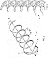
- FIG. 4 illustrates an exemplary body 40 including two intertwined helically wound runners, a first runner 41 and a second runner 42, in the shape or form of a double helix, the body 40 being arranged to form a toroidal shape, the toroidal shape being similar to toroidal shape 10 as shown in FIG. 1 .
- body 40 can be arranged such that the axis of the double helix is not straight but curved, e.g. in a circle or oval.
- the runners of body 40 can be supported by support structures 44.
- a view 40a that illustrates a magnified section of body 40, which includes a section 41a of runner 41, a wire 45 is wound around runner 41.
- wire 45 can be wound clockwise. In some implementations, wire 45 can be arranged and/or wound at a fixed distance of a particular runner, e.g. runner 41. In some implementations, wire 45 can be wound around runner 41 in multiple revolutions, wire 45 being arranged such that runner 41 and wire 45 are separated by a single and constant distance throughout individual ones of the multiple revolutions, the single and constant distance remaining unchanged throughout the individual ones of the multiple revolutions.
- wire 45 can be wound counter-clockwise.
- Wire 45 is conductive.
- Wire 45 can be too fine to be visible in a figure without magnification.
- a wire such as wire 45 can be insulated, uninsulated, or partially insulated and partially uninsulated, as can any wire listed in any figure included in this description.
- a "wire" can include a set of twisted wires (which can interchangeably be referred to as a "twisted wire"), including but not limited to a set of two twisted wires.
- a wire 46 can be wound around runner 42 in a manner similar to wire 45 and runner 41.
- a connector 47 can be electrically coupled to twisted wire 45. For example, as shown in FIG.
- both ends of twisted wire 45 can be electrically coupled to connector 47.
- a connector 48 can be electrically coupled to twisted wire 46.
- both ends of twisted wire 46 can be electrically coupled to connector 48.
- One or more power sources and/or current sources can be electrically coupled to connector 47 and/or connector 48 to supply current to twisted wire 45 and/or twisted wire 46, respectively, such that an electromagnetic effect (e.g. an electromagnetic field) is created around and/or near body 40.
- a system can include one or more bodies that are similar to body 40.
- Such a system can be configured to generate and/or create an electromagnetic effect around and/or near the one or more bodies.
- an electromagnetic effect such a system can be used for agricultural applications, e.g. to promote growth of organisms, and/or be used for other applications.
- such a system can be used to improve and/or promote the health of organisms.
- body 40 can be arranged such that body 40 is substantially vertical. For example, the plane that bisects the toroidal shape of body 40 into two similar, congruent, circular, and/or isometric halves (e.g. as described in relation to FIG.
- the plane that bisects the toroidal shape of body 40 into two similar, congruent, circular, and/or isometric halves can be arranged such that the plane is substantially horizontal.
- body 40 can be constructed such that its diameter is about 10 cm (4 inches), about 15 cm (6 inches), about 20 cm (8 inches), about 25 cm (10 inches), about 30 cm (1 foot), about 45 cm (18 inches), about 60 cm (2 feet), about 75 cm (30 inches), about 90 cm (3 feet), about 120 cm (4 feet), about 150 cm (5 feet), about 180 cm (6 feet), about 210 cm (7 feet), about 240 cm (8 feet), about 270 cm (9 feet), about 300cm (10 feet), and/or other sizes.
- body 40 can have a diameter of about 50 cm (20 inches). In some implementations, body 40 can have a diameter of about 125 or 150 cm (50 or 60 inches).
- FIG. 5 illustrates an exemplary rotatable body 50 that is similar to body 40 in FIG. 4 , except for the addition of rotational elements 51 and 52.
- Body 50 can include components of body 40 that are not depicted in FIG. 5 , and includes two intertwined helically wound runners in the shape of a double helix.
- Body 50 includes a rotational axis 54 through rotational elements 51 and 52.
- Rotatable body 50 is rotatable around rotational axis 54, for example in a direction 53.
- FIG. 6A illustrates an arrangement of a system 60 that includes a rotatable body 61, a support structure 62, a power source 63, and/or other components.
- Body 61 can be similar to body 40 and/or body 50 of FIG. 4 and FIG. 5 .
- Body 61 can include components of body 40 or body 50 that are not depicted in FIG. 6A , and includes two intertwined helically wound runners in the shape of a double helix. Note that some components such as connectors and current sources (described elsewhere in this disclosure) are not depicted in FIG. 6A , but can be included in system 60.
- Support structure 62 is configured to support body 61 in such a way that body 61 is rotatable with respect to support structure 62.
- Power source 63 is configured to provide power to rotate body 61, e.g. via a driveshaft 65 and/or a slip ring (not shown), around a rotational axis.
- system 60 can include one or more rotational elements 64 that are similar or the same as rotational elements 51 and/or 52 in FIG. 5 .
- power source 63 (and/or another power source such as, e.g., a current source) is further configured to provide one or more alternating currents to body 61 (in particular, to a conductive wire wound around a helically wound runner of body 61).
- FIG. 6B illustrates an arrangement of system 60 similar to or the same as system 60 in FIG. 6A , depicted at a different viewing angle.
- System 60 can include a stationary structure 66 in proximity of the center of body 61.
- the stationary structure 66 can be referred to as a treatment chamber.
- Stationary structure 66 can be configured to remain stationary during rotation of body 61.
- stationary structure 66 can be used to support, hold, and/or carry an organism.
- the organism can be any cultivated lifeform(s) - not just animals - used in agriculture applications, medical applications, and/or other applications.
- the organism can include chicken, cow, pig, lamb, goat, bird, fish, crustacean, mollusk, reptile, and/or other animals.
- the organism can include a sample, tissue, stem cells, living cells, and/or any other (organic) matter that can benefit from being subjected to an electromagnetic effect generated by system 60.
- tests have shown that the regeneration period for planarians (after having been cut in half) was reduced from 17 days to 3 days when placed in stationary structure 66.
- the depiction and number of organisms in FIG. 6A/6B is not intended to be limiting in any way.
- FIG. 7 illustrates an arrangement of system 70 similar to or the same as system 60 in FIGs. 6A-6B , depicted at a different viewing angle.
- Support structure 62 is configured to support body 61 in such a way that body 61 is rotatable with respect to support structure 62.
- System 70 can include a stationary structure 66 in proximity of the center of body 61.
- FIG. 8 illustrates an exemplary system 80 that includes one or more of a processor 110, a user interface 120, electronic storage 130, connectors 47 and 48, power source 12, body 40 that includes two intertwined helically wound runners sharing the same circular axis, both runners having conductive wires spirally wound therearound, and/or other components.
- Body 40 can be similar to body 40 shown in FIG. 4 .
- System 80 can include features and/or components depicted in other figures, including but not limited to FIGs. 4-5-6A-6B-7 .
- Body 40 in FIG. 8 is rotatable.
- System 80 includes a power source similar to power source 63 in FIG. 6A .
- Body 40 includes a first runner 41 and a second runner 42.
- a first conductive twisted wire is be wound around first runner 41 and electrically coupled to connector 47 via twisted wire ends 45a and 45c.
- a second conductive twisted wire can be wound around second runner 42 and electrically coupled to connector 48 via twisted wire ends 46a and 46c.
- Connectors 47 and 48 can be electrically coupled to power source 12 such that one or more electric currents are supplied to the twisted wires wound around first runner 41 and second runner 42, such that an electromagnetic effect (e.g. an electromagnetic field) is created around and/or near body 40.
- Body 40 can be arranged near organism 55.
- the depiction of organism 55 as a single element, in this case a planarian, is not meant to be limiting in any way.
- system 80 can include a stationary structure or treatment chamber similar to or the same as stationary structure 66 of FIG. 6A .
- organism 55 can be supported by such a stationary structure, e.g. while body 40
- any two intertwined helically wound runners can share the same axis, be congruent, and/or differ by a translation along the axis, e.g. measuring half the pitch.
- the runners in any bodies in FIGs. 4-5-6A-6B-7-8 can be manufactured from one or more of plastic, plastic plated with metals including copper, nickel, iron, soft iron, nickel alloys, fiberoptic materials, and/or other materials (or combinations thereof). In some implementations, one or more runners can be are manufactured from non-conductive material.
- the number of turns of a set of twisted wires per 2.5 cm (inch) and/or per helical revolution of a runner can be characteristic measurements/features of an implementation of any of the systems described herein.
- the number of twists per 2.5 cm (inch) of a twisted wire can be about 2, about 5, about 10, about 20, about 50, about 100, about 150, about 200, about 250, and/or another suitable number of twists.
- the frequency characteristics of an alternating current and/or the corresponding generated electromagnetic effect or field can be based on, proportional to, and/or otherwise related to the number of twists of a twisted wire.
- a higher number of twists per 2.5 cm (inch) can correspond to (and/or be used with) a higher operating frequency for the alternating current and/or the corresponding generated electromagnetic effect and/or field.
- multiple twisted wires e.g. a first twisted wire wound around a first runner and a second twisted wire wound around a second runner
- multiple wires e.g. twisted wires
- a wire can be wound around some or all of one or more struts.
- the electric currents supplied to the conductive wires wound around the first and second runner of any bodies in FIGs. 4-5-6A-6B-7-8 can flow in the same direction or the opposite direction.
- operating frequencies ranging from more than 0 Hz to about 40 GHz are contemplated.
- the operating frequencies for the conductive wires wound around the first and second runner of any bodies in FIGs. 4-5-6A-6B-7-8 can be the same or different.
- Other electrical operating characteristics of the supplied currents such as phase, amplitude, power-level, and/or other operating characteristics, can be the same or different.
- Systems using any bodies in FIGs. 4-5-6A-6B-7-8 can be used to exploit the electromagnetic field that is created when electrical power is supplied to one or more wires of one or more bodies.
- the conductive wires wound around the first and/or second runner of body 40 are supplied with a first alternating current, e.g. of 216 Hz, and a second alternating current, e.g., of 864 Hz.
- the currents supplied to body 40 can be 180 degrees out of phase.
- Supply of the first and second current can create a beat frequency of 432 Hz (corresponds to an "A" note).
- beat frequencies of 486 Hz, 512 Hz, 576 Hz, 648 Hz, 729 Hz, 768 Hz, and/or other frequencies can be used, which correspond to "B,” "C,” “D,” “E,” “F,” and “G” notes, respectively.
- the rotational speed of a body can be configured to match, correspond, and/or otherwise be related to one or more frequencies in the one or more alternating currents supplied to the conductive wires wound around the runners of any bodies in FIGs. 4-5-6A-6B-7-8 .
- an alternating current of 216 Hz can be combined with a rotational speed of 216 revolutions per second.
- the frequency of the alternating current can be a fraction of the rotational speed, and/or vice versa.
- Applications for any of the systems described herein can include affecting growth and/or growth rate of plants, livestock, samples, tissue, stem cells, living cells, and/or other (organic) matter, medical applications, therapeutic applications, energy production, energy conversion, energy transformation, adenosine triphosphate (ATP) production, ATP transfer, ATP processing, and/or other applications.
- ATP adenosine triphosphate
- Promotion of growth can include one or more of an increased growth rate, an increased maximum growth level, an increased maximum yield, a shorter duration to reach maturity or regeneration, and an increased feed conversion rate.
- the growth rate, or range of typical growth rates, of the particular type of plant can be increased to a higher growth rate, or higher range of growth rates, for the particular plant.
- a unit of growth rate can be 2.5 cm (inch)/day, or another unit expressing some length, area, volume, or size per unit of time, and/or another appropriate unit.
- growth rate can be expressed though lipid production rate, starch content production rate, biomass content production rate.
- a specific type of organism can have a typical maximum growth level, under growing conditions that lack a significant electromagnetic field.
- the maximum growth level, or range of typical maximum growth levels, of the specific type of organism can be increased to a higher maximum growth level, or higher range of maximum growth levels, for the specific organism.
- Maximum growth level can be expressed in cm (inches), square cm (square inches), liters, kilograms, lipid content, and/or another unit expressing some length, area, volume, weight, or size, and/or another appropriate unit.
- a particular type of organism can have a typical maximum yield, under growing conditions that lack a significant electromagnetic field.
- the maximum yield, or range of typical maximum yields, of the particular type of organism can be increased to a higher maximum yield, or higher range of maximum yields, for the particular organism.
- Maximum yield can be expressed in volume or weight per area and/or period, and/or other units as appropriate.
- a particular type of organism can have a typical feed conversion (e.g., a rate or ratio), under farming conditions that lack a significant electromagnetic field.
- a typical feed conversion e.g., a rate or ratio
- the maximum feed conversion, or range of typical maximum feed conversions, of the particular type of organism can be increased to a higher maximum feed conversion, or higher range of maximum feed conversions, for the particular organism.
- feed conversion can be expressed as a percentage of feed that is converted to mass or weight of the organisms, and/or other units as appropriate.
- a system including any of the components shown in FIGs. 4-5-6A-6B-7-8 (and/or multiple instances thereof) can be used as a component in an electrical circuit, performing one or more functions and/or applications including a (broadcast) antenna, a (tunable) inductor, a (Tesla) coil, a transformer, a transducer, a transistor, a resistor, a solenoid, a stator for an electrical motor, an electromagnet, an electromagnetic pulse generator, an electromagnetic actuator, an energy conversion device, a position servomechanism, a generator, a stepping motor, a DC motor, a (contact-free) linear drive, an axial flux device, a measurement device for magnetic permeability, a dipole magnet, a device to alter electron and/or particle trajectory, and/or any combination thereof.
- a (broadcast) antenna a (tunable) inductor, a (Tesla) coil, a transformer, a transducer, a transistor, a
- system 80 can include one or more of user interface 120, one or more physical processors 110, electronic storage 130, one or more power sources and/or current sources (e.g. power source 12a), an input component 111, a playback component 112, a processing component 113, and/or other components.
- power sources and/or current sources e.g. power source 12a
- a system similar to system 80 can include one or more sensors (not shown in FIG. 8 ).
- the one or more sensor can be configured to generate output signals conveying information.
- the information can include electrophysiological information and/or other information.
- the one or more sensors can include one or more of an audio sensor, a microphone, a stethoscope, a pressure sensor, a motion sensor, a proximity sensor, an electromagnetic sensor, an electrode, a temperature sensor, a current sensor, an optical sensor, an electro-optical sensor, and/or other sensors or combinations thereof.
- the one or more processors 110 can be configured to provide information-processing capabilities and/or execute computer program components, including but not limited to input component 111, playback component 112, processing component 113, and/or other components.
- additional structures and/or features of the one or more sensors, processor 110, user interface 120, electronic storage 130, input component 111, playback component 112, and/or processing component 113 are described in U.S. Patent US2014371514 A1 entitled “Health Applications for Using Bio-Feedback to Control an Electromagnetic Field," which was filed February 28, 2014 . This application is referred to as "the'412 application” herein.
- one or more currents supplied to connectors 47 and 48 can correspond to one or more sensor-generated output signals.
- the one or more currents can correspond to one or more signals generated by a transducer and/or one or more other components of system 80.
- an alternating current supplied to body 40 can include a carrier signal and a modulating signal.
- carrier signals used for the alternating current can be radio-frequency signals.
- radio frequency can refer to frequencies between about 30 kHz and about 30 GHz.
- the modulating signals can have a lower frequency than the carrier signal.
- the modulating signal can be in the 10 - 100 MHz range, the 1 - 10 MHz range, the 100 kHZ - 1 MHz range, the 10 - 100 KHz range, the acoustic range, the telephone range, and/or another suitable range.
- the modulating signal for the alternating current can be modulated through one or more of amplitude modulation, frequency modulation, phase modulation, digital modulation, and/or other types of modulation.
- the term "acoustic range” can refer to frequencies between about 20 Hz and about 20 kHz.
- the term “telephone range” can refer to frequencies between about 300 Hz and about 3300 Hz.
- the one or more frequencies included in an alternating current supplied to body can be based on audio recordings of a note, tone, or chord, generated by a frequency generator and/or a (musical) instrument.
- a first frequency can be based on the sound of a piano playing an A above middle C (also referred to as A4, which can include sound having a frequency of about 432 Hz, depending on the tuning system used).
- a second frequency can be based on the sound of some instrument (e.g. a piano) playing a note forming a harmonious interval with A4, which can include sound having a frequency of about 648 Hz.
- This tuning can be referred to as Pythagorean tuning.
- Mathematically perfect tuning can combine notes having a 3:2 ratio. Different types of tuning (or tuning systems), including but not limited to equal tempered tuning, can be used and considered within the scope of this disclosure.
- Processor 110 can include one or more of a digital processor, an analog processor, a digital circuit designed to process information, a central processing unit, a graphics processing unit, an analog circuit designed to process information, and/or other mechanisms for electronically processing information. Although processor 110 is shown in FIG. 8 as a single entity, this is for illustrative purposes only. In some implementations, processor 110 can include a plurality of processing units.
- components 111-113 are illustrated in FIG. 8 as being co-located within a single processing unit, in implementations in which processor 110 includes multiple processing units, one or more of components 111-113 can be located remotely from the other components.
- the description of the functionality provided by the different components 111-113 described herein is for illustrative purposes, and is not intended to be limiting, as any of components 111-113 can provide more or less functionality than is described.
- processor 110 can be configured to execute one or more additional components that can perform some or all of the functionality attributed below to one of components 111-113.
- Input component 111 can be configured to obtain information, e.g. from one or more digital audio files, or, alternatively and/or simultaneously, based on sensor-generate output signals.
- the information can be obtained from storage, e.g. from electronic storage.
- Information obtained from storage can include electronic audio files in any format, including but not limited to MP3, WMA, WAV, AIFF, and/or other audio formats.
- information can be obtained from sound sources including frequency generators, phonographs, CD-players, DVD players, AM radio, FM radio, and/or other sound sources.
- Processing component 113 can be configured to process the obtained information from input component 111. In some implementations, processing component 113 can be configured to generate a processed signal based on the obtained information from input component 111. For example, processing component 113 can convert, filter, modify, and/or otherwise transform information or signals from input component 111 to generate the processed signal.
- Playback component 112 can be configured to produce sound signals based on one or more of the obtained information from input component 111 and/or the processed signal from processing component 113.
- the sound signals produced by playback component 112 can be coupled electrically to the leads/ends of one or more conductive wires wound around one or more runners of body 40 such that the induced current corresponds to and/or is based on the sound signals. Alternatively, and/or simultaneously, the induced current can be controlled by and/or based on the sound signals produced by playback component 112.
- the sound signals produced by playback component 112 can be amplified by an amplifier before being electrically coupled to the leads/end of one or more conductive wires.
- the amplifier can be an audio amplifier ranging between 100 W and 400 W. Other types of amplifiers and/or amplifiers having a different power range are also contemplated.
- Electronic storage 130 in FIG. 8 comprises electronic storage media that electronically stores information.
- the electronic storage media of electronic storage 130 can include one or both of system storage that is provided integrally ( i.e., substantially non-removable) with system 80 and/or removable storage that is connectable to system 80 via, for example, a port (e.g., a USB port, a Firewire port, etc.) or a drive (e.g., a disk drive, etc.).
- a port e.g., a USB port, a Firewire port, etc.
- a drive e.g., a disk drive, etc.
- Electronic storage 130 can include one or more of optically readable storage media (e.g., optical disks, etc.), magnetically readable storage media (e.g., magnetic tape, magnetic hard drive, floppy drive, etc.), electrical charge-based storage media (e.g., EPROM, EEPROM, RAM, etc.), solid-state storage media (e.g., flash drive, etc.), and/or other electronically readable storage media.
- Electronic storage 130 can store software algorithms, information determined by processor 110, information received via user interface 120, and/or other information that enables system 80 to function properly.
- electronic storage 130 can store sound information and/or electronic audio files (as discussed elsewhere herein), and/or other information.
- Electronic storage 130 can be a separate component within system 80, or electronic storage 130 can be provided integrally with one or more other components of system 80 ( e.g ., processor 110).
- User interface 120 of system 80 in FIG. 8 is configured to provide an interface between system 80 and a user (e . g ., a user 108, a caregiver, a therapy decision-maker, etc.) through which the user can provide information to and receive information from system 80.
- a user e . g ., a user 108, a caregiver, a therapy decision-maker, etc.
- This enables data, results, and/or instructions and any other communicable items, collectively referred to as "information,” to be communicated between the user and system 80.
- An example of information that can be conveyed to user 108 is an indication of the volume and/or intensity of the sound signals produced by playback component 112.
- Examples of interface devices suitable for inclusion in user interface 120 include a keypad, buttons, switches, a keyboard, knobs, levers, a display screen, a touch screen, speakers, a microphone, an indicator light, an audible alarm, and a printer.
- Information can be provided to user 108 by user interface 120 in the form of auditory signals, visual signals, tactile signals, and/or other sensory signals.
- user interface 120 can be integrated with a removable storage interface provided by electronic storage 130.
- information is loaded into system 80 from removable storage (e.g., a smart card, a flash drive, a removable disk, etc.) that enables the user(s) to customize system 80.
- removable storage e.g., a smart card, a flash drive, a removable disk, etc.
- Other exemplary input devices and techniques adapted for use with system 80 as user interface 120 include, but are not limited to, an RS-232 port, RF link, an IR link, modem (telephone, cable, Ethernet, internet or other). In short, any technique for communicating information with system 80 is contemplated as user interface 120.
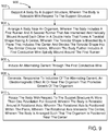
- FIG. 9 illustrates a method 900 for providing electromagnetic effects.
- the operations of method 900 presented below are intended to be illustrative. In certain implementations, method 900 can be accomplished with one or more additional operations not described. Additionally, the order in which the operations of method 900 are illustrated in FIG. 9 and described below is not intended to be limiting.
- method 900 can be implemented in one or more processing devices (e . g ., a digital processor, an analog processor, a digital circuit designed to process information, an analog circuit designed to process information, and/or other mechanisms for electronically processing information).
- the one or more processing devices can include one or more devices executing some or all of the operations of method 900 in response to instructions stored electronically on an electronic storage medium.
- the one or more processing devices can include one or more devices configured through hardware, firmware, and/or software to be specifically designed for execution of one or more of the operations of method 900.
- a body is supported by a support structure.
- the body is rotatable with respect to the support structure.
- operation 902 is performed by a support structure the same as or similar to support structure 62 (shown in FIG. 6A and described herein).
- a body is arranged near an organism.
- the body includes a first runner and a second runner that are intertwined and helically wound around each other in a double helix that forms a toroidal shape having a center.
- the toroidal shape is bisected by a plane that includes the center and divides the toroidal shape into two similar circular halves.
- the body further includes a first conductive wire spirally wound around the first runner.
- operation 904 is performed by a body the same as or similar to body 61 (shown in FIG. 6A and described herein).
- an alternating current is induced through the first conductive wire.
- operation 906 is performed by a power source the same as or similar to power source 12 (shown in FIG. 8 and described herein).
- operation 908 responsive to induction of the alternating current, an electromagnetic effect is generated at or near the organism that promotes growth of the organism.
- operation 908 is performed by a body the same as or similar to body 61 and/or 40 (shown in FIG. 6A and/or 8 and described herein).
- the body is rotated with respect to the support structure at more than one revolution per second.
- the body is rotatable around a rotational axis.
- the rotational axis is positioned within the plane.
- the rotational axis intersects the center.
- the body is arranged such that the organism is positioned near the center.
- operation 910 is performed by a power source the same as or similar to power source 63 (shown in FIG. 6A and described herein).
Landscapes
- Engineering & Computer Science (AREA)
- Health & Medical Sciences (AREA)
- Life Sciences & Earth Sciences (AREA)
- Power Engineering (AREA)
- Physics & Mathematics (AREA)
- Electromagnetism (AREA)
- Zoology (AREA)
- Chemical & Material Sciences (AREA)
- Organic Chemistry (AREA)
- Wood Science & Technology (AREA)
- Genetics & Genomics (AREA)
- Bioinformatics & Cheminformatics (AREA)
- Biomedical Technology (AREA)
- General Health & Medical Sciences (AREA)
- Biotechnology (AREA)
- General Engineering & Computer Science (AREA)
- Microbiology (AREA)
- Biochemistry (AREA)
- Veterinary Medicine (AREA)
- Animal Behavior & Ethology (AREA)
- Radiology & Medical Imaging (AREA)
- Nuclear Medicine, Radiotherapy & Molecular Imaging (AREA)
- Public Health (AREA)
- Cell Biology (AREA)
- Sustainable Development (AREA)
- Magnetic Treatment Devices (AREA)
Claims (14)
- System (60, 70, 80), das Folgendes umfasst:eine Tragstruktur (62), konfiguriert zum Tragen eines Körpers (30, 40, 50, 61), wobei der Körper (30, 40, 50, 61) in Bezug auf die Tragstruktur drehbar ist;wobei der Körper (30, 40, 50, 61) Folgendes beinhaltet:eine erste Laufschiene (31, 41) und eine zweite Laufschiene (32, 42), die in einer eine toroidale Form bildenden Doppelhelix miteinander verflochten und schneckenförmig umeinander gewickelt sind, wobei die toroidale Form ein Zentrum hat, wobei die toroidale Form durch eine Ebene halbiert wird, die das Zentrum beinhaltet und die toroidale Form in zwei ähnliche kreisförmige Hälften teilt; undeinen ersten leitfähigen Draht (45), der spiralförmig um die erste Laufschiene (31, 41) gewickelt ist; undeine oder mehrere Energiequellen (63), konfiguriert zum Zuführen eines Wechselstroms zu dem ersten leitfähigen Draht und konfiguriert zum Zuführen von Energie, um den Körper (30, 40, 50, 61) in Bezug auf die Tragstruktur mit mehr als einer Umdrehung pro Sekunde zu drehen,wobei der Körper (30, 40, 50, 61) um eine Drehachse drehbar ist, wobei die Drehachse innerhalb der Ebene positioniert ist, wobei die Drehachse das Zentrum schneidet, wobei der Körper (30, 40, 50, 61) zum Aufnehmen eines Organismus in der Nähe des Zentrums konfiguriert ist, undwobei das System zum Erzeugen eines elektromagnetischen Effekts als Reaktion auf den zugeführten Wechselstrom konfiguriert ist.
- System nach Anspruch 1, wobei sich der Körper mit einer bestimmten Anzahl von Umdrehungen pro Sekunde dreht und wobei die bestimmte Anzahl von Umdrehungen einer Frequenz des Wechselstroms entspricht.
- System nach Anspruch 1, wobei der erste leitfähige Draht in einem festen Abstand von der ersten Laufschiene angeordnet ist; und wobei der erste leitfähige Draht optional ein verdrillter Draht ist.
- System nach Anspruch 1, wobei die ein oder mehreren Stromquellen ferner so konfiguriert sind, dass der Wechselstrom eine durch ein akustisches Signal modulierte Trägerwelle aufweist, wobei die Trägerwelle eine höhere Frequenz als das akustische Signal aufweist; und wobei die Frequenz der Trägerwelle optional zwischen 1 MHz und 1 GHz liegt.
- System nach Anspruch 1, wobei die Doppelhelix des Körpers einen Durchmesser zwischen 10 cm und 300 cm hat.
- System nach Anspruch 1, das ferner Folgendes umfasst:einen oder mehrere physikalische Prozessoren (110), die über computerlesbare Befehle konfiguriert sind zum:
Einholen von Informationen, die eine oder mehrere digitale Audiodateien beinhalten; Verarbeiten der eingeholten Informationen und Erzeugen eines verarbeiteten Signals auf der Basis der eingeholten Informationen, und Erzeugen von Tonsignalen auf der Basis des verarbeiteten Signals,wobei der Wechselstrom dynamisch geregelt wird, so dass er den erzeugten Tonsignalen entspricht, so dass eine oder mehrere Frequenzen des Wechselstroms einer oder mehreren Frequenzen der erzeugten Tonsignale entsprechen. - System nach Anspruch 1, das ferner einen Signalgenerator umfasst, der zum Erzeugen eines Signals mit einer bestimmten Frequenz konfiguriert ist, wobei der Wechselstrom und/oder die zum Drehen des Körpers zugeführte Energie dynamisch geregelt wird/werden, so dass sie dem vom Signalgenerator erzeugten Signal entsprechen.
- Verfahren zum Bereitstellen von elektromagnetischen Effekten, wobei das Verfahren Folgendes beinhaltet:Tragen eines Körpers (30, 40, 50, 61) durch eine Tragstruktur (62), wobei der Körper (30, 40, 50, 61) in Bezug auf die Tragstruktur drehbar ist;Anordnen eines Körpers (30, 40, 50, 61) in der Nähe eines Organismus, wobei der Körper (30, 40, 50, 61) eine erste Laufschiene (31, 41) und eine zweite Laufschiene (32, 42) beinhaltet, die in einer eine toroidale Form mit einem Zentrum bildenden Doppelhelix miteinander verflochten und schneckenförmig umeinander gewickelt sind, wobei die toroidale Form durch eine Ebene halbiert wird, die das Zentrum beinhaltet und die toroidale Form in zwei ähnliche kreisförmige Hälften teilt, wobei der Körper (30, 40, 50, 61) ferner einen ersten leitfähigen Draht (45) beinhaltet, der spiralförmig um die erste Laufschiene gewickelt ist;Induzieren eines Wechselstroms durch den ersten leitfähigen Draht;Erzeugen eines elektromagnetischen Effekts an oder in der Nähe des Organismus, der das Wachstum des Organismus fördert, als Reaktion auf die Induktion des Wechselstroms;Drehen des Körpers (30, 40, 50, 61) in Bezug auf die Tragstruktur mit mehr als einer Umdrehung pro Sekunde,wobei der Körper (30, 40, 50, 61) um eine Drehachse drehbar ist, wobei die Drehachse innerhalb der Ebene positioniert ist, wobei die Drehachse das Zentrum schneidet, wobei der Körper (30, 40, 50, 61) so angeordnet ist, dass der Organismus in der Nähe des Zentrums positioniert ist.
- Verfahren nach Anspruch 8, wobei das Drehen des Körpers das Drehen des Körpers mit einer bestimmten Anzahl von Umdrehungen pro Sekunde beinhaltet, und wobei die bestimmte Anzahl von Umdrehungen einer Frequenz des Wechselstroms entspricht.
- Verfahren nach Anspruch 8, wobei das Anordnen des Körpers das Wickeln des ersten leitfähigen Drahtes in einem festen Abstand von der ersten Laufschiene beinhaltet; und optional das Verdrillen des ersten leitfähigen Drahtes zu einem verdrillten Draht beinhaltet.
- Verfahren nach Anspruch 8, wobei das Induzieren des Wechselstroms so durchgeführt wird, dass der Wechselstrom eine durch ein akustisches Signal modulierte Trägerwelle aufweist, wobei die Trägerwelle eine höhere Frequenz als das akustische Signal aufweist; und wobei die Frequenz der Trägerwelle optional zwischen 1 MHz und 1 GHz liegt.
- Verfahren nach Anspruch 8, wobei das Erzeugen des elektromagnetischen Effekts das Fördern des Wachstums des Organismus durch eines oder mehrere aus einer erhöhten Wachstumsrate, einem erhöhten maximalen Wachstumsniveau, einem erhöhten maximalen Ertrag und einer erhöhten Futterverwertungsrate bewirkt.
- Verfahren nach Anspruch 8, das ferner Folgendes beinhaltet:Einholen von Informationen, die eine oder mehrere digitale Audiodateien beinhalten;Verarbeiten der eingeholten Informationen und Erzeugen eines verarbeiteten Signals auf der Basis der eingeholten Informationen, undErzeugen von Tonsignalen auf der Basis des verarbeiteten Signals,wobei das Induzieren des Wechselstroms das dynamische Regeln des Wechselstroms beinhaltet, so dass er den erzeugten Tonsignalen entspricht, so dass eine oder mehrere Frequenzen des Wechselstroms einer oder mehreren Frequenzen der erzeugten Tonsignale entsprechen.
- Verfahren nach Anspruch 8, das ferner Folgendes beinhaltet:Erzeugen eines Signals mit einer bestimmten Frequenz,wobei der Wechselstrom und/oder die zum Drehen des Körpers zugeführte Energie dynamisch geregelt wird/werden, so dass sie dem Signal entsprechen.
Priority Applications (2)
| Application Number | Priority Date | Filing Date | Title |
|---|---|---|---|
| DK21217050.0T DK4075457T3 (da) | 2015-09-01 | 2016-08-31 | Roterende dobbeltspiral-dobbeltleder |
| EP21217050.0A EP4075457B1 (de) | 2015-09-01 | 2016-08-31 | Rotierender doppelhelix-doppelleiter |
Applications Claiming Priority (2)
| Application Number | Priority Date | Filing Date | Title |
|---|---|---|---|
| US201562283464P | 2015-09-01 | 2015-09-01 | |
| PCT/EP2016/070558 WO2017037143A1 (en) | 2015-09-01 | 2016-08-31 | Rotating dual double helix conductors |
Related Child Applications (1)
| Application Number | Title | Priority Date | Filing Date |
|---|---|---|---|
| EP21217050.0A Division EP4075457B1 (de) | 2015-09-01 | 2016-08-31 | Rotierender doppelhelix-doppelleiter |
Publications (2)
| Publication Number | Publication Date |
|---|---|
| EP3345199A1 EP3345199A1 (de) | 2018-07-11 |
| EP3345199B1 true EP3345199B1 (de) | 2021-12-29 |
Family
ID=57044905
Family Applications (2)
| Application Number | Title | Priority Date | Filing Date |
|---|---|---|---|
| EP21217050.0A Active EP4075457B1 (de) | 2015-09-01 | 2016-08-31 | Rotierender doppelhelix-doppelleiter |
| EP16774861.5A Active EP3345199B1 (de) | 2015-09-01 | 2016-08-31 | Leiter mit rotierender dualer doppelhelix |
Family Applications Before (1)
| Application Number | Title | Priority Date | Filing Date |
|---|---|---|---|
| EP21217050.0A Active EP4075457B1 (de) | 2015-09-01 | 2016-08-31 | Rotierender doppelhelix-doppelleiter |
Country Status (7)
| Country | Link |
|---|---|
| US (1) | US10155925B2 (de) |
| EP (2) | EP4075457B1 (de) |
| JP (1) | JP6868626B2 (de) |
| CA (1) | CA2996912C (de) |
| DK (2) | DK4075457T3 (de) |
| ES (1) | ES2907293T3 (de) |
| WO (1) | WO2017037143A1 (de) |
Families Citing this family (4)
| Publication number | Priority date | Publication date | Assignee | Title |
|---|---|---|---|---|
| US20190269877A1 (en) * | 2018-03-05 | 2019-09-05 | Dennis Yat Wong | Electromagnetic resonant frequency coil ion emitter |
| EP4009770A4 (de) * | 2019-08-09 | 2023-09-06 | Bright Yeti, Inc. | Elektromagnetische behandlung von erntegut |
| DE102021101671A1 (de) * | 2021-01-26 | 2022-07-28 | Centropix Global Ag | Vorrichtung zur Magnetfeldtherapie |
| US11612109B1 (en) * | 2022-02-24 | 2023-03-28 | Welivitigoda Rajitha Danesha Wimaladharma | Magnetic device and method for growing plants |
Family Cites Families (87)
| Publication number | Priority date | Publication date | Assignee | Title |
|---|---|---|---|---|
| FR719837A (fr) | 1930-10-13 | 1932-02-10 | Telefunken Gmbh | Perfectionnements aux antennes directives pour ondes courtes |
| US2035274A (en) | 1932-01-12 | 1936-03-24 | Bell Telephone Labor Inc | Coaxial conductor system |
| GB479841A (en) | 1935-08-12 | 1938-02-07 | Siemens Ag | Improvements in or relating to air-space-insulated high frequency electric cables |
| IT392129A (de) | 1940-01-20 | |||
| US2850666A (en) | 1955-12-01 | 1958-09-02 | Hughes Aircraft Co | Helix structure for traveling-wave tubes |
| US3037175A (en) | 1958-05-12 | 1962-05-29 | Bell Telephone Labor Inc | Broadband transformers |
| GB930382A (de) | 1959-04-16 | |||
| US3519964A (en) | 1968-07-26 | 1970-07-07 | Microwave Ass | High power slow wave circuit |
| US3588689A (en) | 1969-06-16 | 1971-06-28 | Harry F Crawford | Variable impedance system for electrical cable fault locating and temperature monitoring |
| US3683393A (en) | 1970-07-06 | 1972-08-08 | Electrotec Corp | Helical dipole antenna |
| US3760812A (en) | 1971-03-19 | 1973-09-25 | Univ Minnesota | Implantable spiral wound stimulation electrodes |
| US3774452A (en) | 1971-11-22 | 1973-11-27 | Meter Service & Supply Co | Helical coil bourdon tube support assembly |
| US4266532A (en) | 1976-11-17 | 1981-05-12 | Electro-Biology, Inc. | Modification of the growth, repair and maintenance behavior of living tissues and cells by a specific and selective change in electrical environment |
| US4131759A (en) | 1977-08-10 | 1978-12-26 | United States Steel Corporation | Slip sleeve mechanism for a strength tapered caged armored electromechanical cable |
| US4229676A (en) | 1979-03-16 | 1980-10-21 | Hughes Aircraft Company | Helical slow-wave structure assemblies and fabrication methods |
| DE3050586A1 (de) | 1980-09-29 | 1982-09-23 | Od Polt Institut | Electric motor with screw-shaped stator |
| US4489276A (en) | 1982-01-20 | 1984-12-18 | The United States Of America As Represented By The United States Department Of Energy | Dual-cone double-helical downhole logging device |
| US4832051A (en) | 1985-04-29 | 1989-05-23 | Symbion, Inc. | Multiple-electrode intracochlear device |
| JP2628498B2 (ja) | 1987-09-03 | 1997-07-09 | シユスター、ペーター | 非接触直線駆動装置 |
| US4989617A (en) | 1989-07-14 | 1991-02-05 | Case Western Reserve University | Intramuscular electrode for neuromuscular stimulation system |
| US5077934A (en) | 1989-09-22 | 1992-01-07 | Life Resonances, Inc. | Method and apparatus for controlling plant growth |
| US5851206A (en) | 1990-03-13 | 1998-12-22 | The Regents Of The University Of California | Method and apparatus for endovascular thermal thrombosis and thermal cancer treatment |
| US5173669A (en) | 1990-09-04 | 1992-12-22 | Hughes Aircraft Company | Slow-wave structure having block supported helix structure |
| NL9002005A (nl) | 1990-09-12 | 1992-04-01 | Philips Nv | Transformator. |
| US5366493A (en) | 1991-02-04 | 1994-11-22 | Case Western Reserve University | Double helix functional stimulation electrode |
| US5359340A (en) | 1992-09-30 | 1994-10-25 | Fujitsu Limited | Helical antenna for portable radio communication equipment |
| US5654723A (en) | 1992-12-15 | 1997-08-05 | West Virginia University | Contrawound antenna |
| US5339061A (en) | 1993-06-01 | 1994-08-16 | Michael Ebert | Iron-free transformer |
| US5464456A (en) | 1993-06-30 | 1995-11-07 | Kertz; M. Glen | Electronic stimulation of plants |
| CA2131950A1 (en) | 1993-09-16 | 1995-03-17 | Kazumi Masaki | Fm theta-inducing audible sound, and method, device and recorded medium to generate the same |
| EP0666612B1 (de) | 1994-02-04 | 2001-10-24 | Orbital Sciences Corporation | Sich selbst entfaltende Wendelstruktur |
| US5819467A (en) | 1994-12-05 | 1998-10-13 | Zucker; Jonathan M. | Method of stimulating plant growth |
| US6239760B1 (en) | 1995-08-14 | 2001-05-29 | Vortekx, Inc. | Contrawound toroidal helical antenna |
| US6042605A (en) | 1995-12-14 | 2000-03-28 | Gore Enterprose Holdings, Inc. | Kink resistant stent-graft |
| US6552530B1 (en) | 1997-10-14 | 2003-04-22 | Hex Technology Holding Limited | Super-toroidal electric and magnetic field generator/detector, and sample analyser and treatment apparatus using same |
| US5892480A (en) | 1997-04-09 | 1999-04-06 | Harris Corporation | Variable pitch angle, axial mode helical antenna |
| US5909165A (en) | 1997-08-29 | 1999-06-01 | The United States Of America As Represented By The Secretary Of The Army | Chiron twister |
| US6005462A (en) | 1998-02-24 | 1999-12-21 | Myers; John Leonard | Electromagnetic core-energy actuator |
| US6169523B1 (en) | 1999-01-13 | 2001-01-02 | George Ploussios | Electronically tuned helix radiator choke |
| WO2001080360A1 (en) * | 2000-04-15 | 2001-10-25 | Morrison, Ian | Apparatus for generating electric and/or magnetic fields and detecting and using such fields |
| EP1297589A1 (de) | 2000-04-15 | 2003-04-02 | MedTech Corporation | Vorrichtung zur elektromagnetischen spektroskopie |
| US6300920B1 (en) | 2000-08-10 | 2001-10-09 | West Virginia University | Electromagnetic antenna |
| US6856078B2 (en) | 2001-06-27 | 2005-02-15 | Asm America, Inc. | Lamp filament design |
| US6921042B1 (en) | 2001-09-24 | 2005-07-26 | Carl L. Goodzeit | Concentric tilted double-helix dipoles and higher-order multipole magnets |
| US6819210B2 (en) | 2001-11-13 | 2004-11-16 | Kci Licensing, Inc. | Static magnetic field, method of creation, and resting surface therein |
| US20030158585A1 (en) | 2002-02-19 | 2003-08-21 | Burnett Daniel R. | Method and apparatus for electromagnetic stimulation of nerve, muscle, and body tissues |
| US6978179B1 (en) | 2002-02-27 | 2005-12-20 | Flagg Rodger H | Method and apparatus for magnetic brain wave stimulation |
| WO2003094178A1 (en) | 2002-05-02 | 2003-11-13 | Belden Technologies, Inc. | Surfaced cable filler |
| US7154368B2 (en) | 2003-10-15 | 2006-12-26 | Actown Electricoil, Inc. | Magnetic core winding method, apparatus, and product produced therefrom |
| US20050121396A1 (en) | 2003-12-09 | 2005-06-09 | Kosakewich Darrell S. | Apparatus and method for treating substances with electromagnetic wave energy |
| US7520848B2 (en) * | 2004-04-09 | 2009-04-21 | The Board Of Trustees Of The Leland Stanford Junior University | Robotic apparatus for targeting and producing deep, focused transcranial magnetic stimulation |
| US7148783B2 (en) | 2004-11-05 | 2006-12-12 | Harris Corporation | Microwave tunable inductor and associated methods |
| US20080161884A1 (en) | 2004-12-23 | 2008-07-03 | Mark Chandler | Method and apparatus for treating or preventing a medical condition |
| US20070258329A1 (en) | 2005-01-27 | 2007-11-08 | Timothy Winey | Method and apparatus for the exploitation of piezoelectric and other effects in carbon-based life forms |
| US20070024520A1 (en) | 2005-07-14 | 2007-02-01 | Duane Preble | Spiral antenna |
| US20100152811A1 (en) | 2006-06-30 | 2010-06-17 | Flaherty Christopher J | Nerve regeneration system and lead devices associated therewith |
| US7375449B2 (en) | 2006-08-17 | 2008-05-20 | Butterfield Paul D | Optimized modular electrical machine using permanent magnets |
| JP5250820B2 (ja) * | 2006-12-26 | 2013-07-31 | 株式会社アドメテック | 磁場発生アプリケータ、及び、磁場発生装置 |
| US7998139B2 (en) | 2007-04-25 | 2011-08-16 | Vivant Medical, Inc. | Cooled helical antenna for microwave ablation |
| US9114251B2 (en) | 2007-04-25 | 2015-08-25 | St. Jude Medical Ab | Medical implantable lead and a method for attaching the same |
| US8001672B2 (en) | 2007-10-02 | 2011-08-23 | Advanced Magnet Lab, Inc | Methods of fabricating a conductor assembly having a curvilinear arcuate shape |
| US7889042B2 (en) | 2008-02-18 | 2011-02-15 | Advanced Magnet Lab, Inc. | Helical coil design and process for direct fabrication from a conductive layer |
| US7674973B2 (en) | 2008-04-18 | 2010-03-09 | George Cardas | Electrical conductor and cable utilizing same |
| US20100005711A1 (en) | 2008-07-09 | 2010-01-14 | Sartec Corporation | Lighted Algae Cultivation Systems |
| CN102186538B (zh) | 2008-08-25 | 2016-11-16 | 应用磁学有限责任公司 | 用于向对象提供磁共振治疗的系统和方法 |
| US20100113862A1 (en) | 2008-11-05 | 2010-05-06 | Kotowich Alan W J | Treatment of amelioration of arthritic joint pain |
| US20100121131A1 (en) | 2008-11-11 | 2010-05-13 | Mathes Richard A | Apparatus and methods for stimulating a body's natural healing mechanisms |
| US8332042B2 (en) | 2009-01-15 | 2012-12-11 | Medtronic, Inc. | Medical lead with stiffening coil |
| US8463407B2 (en) | 2009-03-26 | 2013-06-11 | Kenergy, Inc. | MRI compatible implanted lead-electrode interface |
| US9375585B2 (en) | 2009-06-17 | 2016-06-28 | Nexstim Oy | Magnetic stimulation device and method |
| US20130274542A1 (en) | 2010-04-30 | 2013-10-17 | Periso Sa | Medical device for treatment of human parasitism and of related diseases |
| GB2480610A (en) | 2010-05-24 | 2011-11-30 | Iain Norman Reid Findlay | Flexible tubing arranged on a support structure for growing plants |
| US20120143285A1 (en) | 2010-10-07 | 2012-06-07 | Jian Wang | Handheld excitation terminal and emf emitter providing dynamic optimization of emission and therapeutic effect and remote therapeutic system |
| US8653925B2 (en) | 2011-03-03 | 2014-02-18 | Lifewave, Inc. | Double helix conductor |
| US8919035B2 (en) | 2012-01-27 | 2014-12-30 | Medical Energetics Ltd | Agricultural applications of a double helix conductor |
| US8652023B2 (en) * | 2012-02-13 | 2014-02-18 | Lifewave, Inc. | Health applications of a double helix conductor |
| US8749333B2 (en) | 2012-04-26 | 2014-06-10 | Lifewave, Inc. | System configuration using a double helix conductor |
| US9504844B2 (en) * | 2013-06-12 | 2016-11-29 | Medical Energetics Ltd | Health applications for using bio-feedback to control an electromagnetic field |
| US9636518B2 (en) | 2013-10-28 | 2017-05-02 | Medical Energetics Ltd. | Nested double helix conductors |
| US20150119630A1 (en) | 2013-10-28 | 2015-04-30 | Medical Energetics Ltd. | Double helix conductor with fiberoptic cable for producing effects in living organisms |
| US9724531B2 (en) | 2013-10-28 | 2017-08-08 | Medical Energetics Ltd. | Double helix conductor with light emitting fluids for producing photobiomodulation effects in living organisms |
| US9717926B2 (en) | 2014-03-05 | 2017-08-01 | Medical Energetics Ltd. | Double helix conductor with eight connectors and counter-rotating fields |
| US9463331B2 (en) | 2014-04-07 | 2016-10-11 | Medical Energetics Ltd | Using a double helix conductor to treat neuropathic disorders |
| US9370667B2 (en) | 2014-04-07 | 2016-06-21 | Medical Energetics Ltd | Double helix conductor for medical applications using stem cell technology |
| AU2015201169A1 (en) | 2014-04-10 | 2015-10-29 | Medical Energetics Ltd. | Double helix conductor with counter-rotating fields |
| US10102955B2 (en) | 2015-02-20 | 2018-10-16 | Medical Energetics Ltd. | Dual double helix conductors |
| WO2016198265A1 (en) | 2015-06-09 | 2016-12-15 | Medical Energetics Ltd. | Dual double helix conductors used in agriculture |
-
2016
- 2016-08-31 DK DK21217050.0T patent/DK4075457T3/da active
- 2016-08-31 EP EP21217050.0A patent/EP4075457B1/de active Active
- 2016-08-31 DK DK16774861.5T patent/DK3345199T3/da active
- 2016-08-31 ES ES16774861T patent/ES2907293T3/es active Active
- 2016-08-31 EP EP16774861.5A patent/EP3345199B1/de active Active
- 2016-08-31 CA CA2996912A patent/CA2996912C/en active Active
- 2016-08-31 WO PCT/EP2016/070558 patent/WO2017037143A1/en not_active Ceased
- 2016-08-31 JP JP2018529741A patent/JP6868626B2/ja active Active
- 2016-08-31 US US15/253,678 patent/US10155925B2/en active Active
Non-Patent Citations (1)
| Title |
|---|
| None * |
Also Published As
| Publication number | Publication date |
|---|---|
| DK4075457T3 (da) | 2025-05-12 |
| ES2907293T3 (es) | 2022-04-22 |
| CA2996912A1 (en) | 2017-03-09 |
| EP4075457B1 (de) | 2025-03-12 |
| JP2018537102A (ja) | 2018-12-20 |
| CA2996912C (en) | 2024-06-04 |
| EP3345199A1 (de) | 2018-07-11 |
| EP4075457A1 (de) | 2022-10-19 |
| US10155925B2 (en) | 2018-12-18 |
| JP6868626B2 (ja) | 2021-05-12 |
| US20170058251A1 (en) | 2017-03-02 |
| WO2017037143A1 (en) | 2017-03-09 |
| DK3345199T3 (da) | 2022-02-28 |
Similar Documents
| Publication | Publication Date | Title |
|---|---|---|
| US10224136B2 (en) | Dual double helix conductors used in agriculture | |
| US10102955B2 (en) | Dual double helix conductors | |
| US9636518B2 (en) | Nested double helix conductors | |
| US10497508B2 (en) | Double helix conductor with counter rotating fields | |
| US9717926B2 (en) | Double helix conductor with eight connectors and counter-rotating fields | |
| US9504845B2 (en) | Health applications of a double helix conductor | |
| US20150119630A1 (en) | Double helix conductor with fiberoptic cable for producing effects in living organisms | |
| EP3345199B1 (de) | Leiter mit rotierender dualer doppelhelix | |
| US9827436B2 (en) | Systems and methods to improve the growth rate of livestock, fish, and other animals | |
| WO2016131937A2 (en) | Dual double helix conductors | |
| US10688309B2 (en) | Double helix conductor with winding around core | |
| HK1226857B (en) | Double helix conductor with eight connectors and counter-rotating fields | |
| HK1226857A1 (en) | Double helix conductor with eight connectors and counter-rotating fields |
Legal Events
| Date | Code | Title | Description |
|---|---|---|---|
| STAA | Information on the status of an ep patent application or granted ep patent |
Free format text: STATUS: THE INTERNATIONAL PUBLICATION HAS BEEN MADE |
|
| PUAI | Public reference made under article 153(3) epc to a published international application that has entered the european phase |
Free format text: ORIGINAL CODE: 0009012 |
|
| STAA | Information on the status of an ep patent application or granted ep patent |
Free format text: STATUS: REQUEST FOR EXAMINATION WAS MADE |
|
| 17P | Request for examination filed |
Effective date: 20180326 |
|
| AK | Designated contracting states |
Kind code of ref document: A1 Designated state(s): AL AT BE BG CH CY CZ DE DK EE ES FI FR GB GR HR HU IE IS IT LI LT LU LV MC MK MT NL NO PL PT RO RS SE SI SK SM TR |
|
| AX | Request for extension of the european patent |
Extension state: BA ME |
|
| DAV | Request for validation of the european patent (deleted) | ||
| DAX | Request for extension of the european patent (deleted) | ||
| STAA | Information on the status of an ep patent application or granted ep patent |
Free format text: STATUS: EXAMINATION IS IN PROGRESS |
|
| 17Q | First examination report despatched |
Effective date: 20191211 |
|
| GRAP | Despatch of communication of intention to grant a patent |
Free format text: ORIGINAL CODE: EPIDOSNIGR1 |
|
| STAA | Information on the status of an ep patent application or granted ep patent |
Free format text: STATUS: GRANT OF PATENT IS INTENDED |
|
| INTG | Intention to grant announced |
Effective date: 20210607 |
|
| GRAS | Grant fee paid |
Free format text: ORIGINAL CODE: EPIDOSNIGR3 |
|
| GRAA | (expected) grant |
Free format text: ORIGINAL CODE: 0009210 |
|
| STAA | Information on the status of an ep patent application or granted ep patent |
Free format text: STATUS: THE PATENT HAS BEEN GRANTED |
|
| AK | Designated contracting states |
Kind code of ref document: B1 Designated state(s): AL AT BE BG CH CY CZ DE DK EE ES FI FR GB GR HR HU IE IS IT LI LT LU LV MC MK MT NL NO PL PT RO RS SE SI SK SM TR |
|
| REG | Reference to a national code |
Ref country code: GB Ref legal event code: FG4D |
|
| REG | Reference to a national code |
Ref country code: CH Ref legal event code: EP |
|
| REG | Reference to a national code |
Ref country code: DE Ref legal event code: R096 Ref document number: 602016067852 Country of ref document: DE |
|
| REG | Reference to a national code |
Ref country code: AT Ref legal event code: REF Ref document number: 1459303 Country of ref document: AT Kind code of ref document: T Effective date: 20220115 |
|
| REG | Reference to a national code |
Ref country code: IE Ref legal event code: FG4D |
|
| REG | Reference to a national code |
Ref country code: DK Ref legal event code: T3 Effective date: 20220225 |
|
| REG | Reference to a national code |
Ref country code: LT Ref legal event code: MG9D |
|
| REG | Reference to a national code |
Ref country code: ES Ref legal event code: FG2A Ref document number: 2907293 Country of ref document: ES Kind code of ref document: T3 Effective date: 20220422 |
|
| PG25 | Lapsed in a contracting state [announced via postgrant information from national office to epo] |
Ref country code: RS Free format text: LAPSE BECAUSE OF FAILURE TO SUBMIT A TRANSLATION OF THE DESCRIPTION OR TO PAY THE FEE WITHIN THE PRESCRIBED TIME-LIMIT Effective date: 20211229 Ref country code: LT Free format text: LAPSE BECAUSE OF FAILURE TO SUBMIT A TRANSLATION OF THE DESCRIPTION OR TO PAY THE FEE WITHIN THE PRESCRIBED TIME-LIMIT Effective date: 20211229 Ref country code: FI Free format text: LAPSE BECAUSE OF FAILURE TO SUBMIT A TRANSLATION OF THE DESCRIPTION OR TO PAY THE FEE WITHIN THE PRESCRIBED TIME-LIMIT Effective date: 20211229 Ref country code: BG Free format text: LAPSE BECAUSE OF FAILURE TO SUBMIT A TRANSLATION OF THE DESCRIPTION OR TO PAY THE FEE WITHIN THE PRESCRIBED TIME-LIMIT Effective date: 20220329 |
|
| REG | Reference to a national code |
Ref country code: NL Ref legal event code: MP Effective date: 20211229 |
|
| REG | Reference to a national code |
Ref country code: AT Ref legal event code: MK05 Ref document number: 1459303 Country of ref document: AT Kind code of ref document: T Effective date: 20211229 |
|
| PG25 | Lapsed in a contracting state [announced via postgrant information from national office to epo] |
Ref country code: SE Free format text: LAPSE BECAUSE OF FAILURE TO SUBMIT A TRANSLATION OF THE DESCRIPTION OR TO PAY THE FEE WITHIN THE PRESCRIBED TIME-LIMIT Effective date: 20211229 Ref country code: NO Free format text: LAPSE BECAUSE OF FAILURE TO SUBMIT A TRANSLATION OF THE DESCRIPTION OR TO PAY THE FEE WITHIN THE PRESCRIBED TIME-LIMIT Effective date: 20220329 Ref country code: LV Free format text: LAPSE BECAUSE OF FAILURE TO SUBMIT A TRANSLATION OF THE DESCRIPTION OR TO PAY THE FEE WITHIN THE PRESCRIBED TIME-LIMIT Effective date: 20211229 Ref country code: HR Free format text: LAPSE BECAUSE OF FAILURE TO SUBMIT A TRANSLATION OF THE DESCRIPTION OR TO PAY THE FEE WITHIN THE PRESCRIBED TIME-LIMIT Effective date: 20211229 Ref country code: GR Free format text: LAPSE BECAUSE OF FAILURE TO SUBMIT A TRANSLATION OF THE DESCRIPTION OR TO PAY THE FEE WITHIN THE PRESCRIBED TIME-LIMIT Effective date: 20220330 |
|
| PG25 | Lapsed in a contracting state [announced via postgrant information from national office to epo] |
Ref country code: NL Free format text: LAPSE BECAUSE OF FAILURE TO SUBMIT A TRANSLATION OF THE DESCRIPTION OR TO PAY THE FEE WITHIN THE PRESCRIBED TIME-LIMIT Effective date: 20211229 |
|
| PG25 | Lapsed in a contracting state [announced via postgrant information from national office to epo] |
Ref country code: SM Free format text: LAPSE BECAUSE OF FAILURE TO SUBMIT A TRANSLATION OF THE DESCRIPTION OR TO PAY THE FEE WITHIN THE PRESCRIBED TIME-LIMIT Effective date: 20211229 Ref country code: SK Free format text: LAPSE BECAUSE OF FAILURE TO SUBMIT A TRANSLATION OF THE DESCRIPTION OR TO PAY THE FEE WITHIN THE PRESCRIBED TIME-LIMIT Effective date: 20211229 Ref country code: RO Free format text: LAPSE BECAUSE OF FAILURE TO SUBMIT A TRANSLATION OF THE DESCRIPTION OR TO PAY THE FEE WITHIN THE PRESCRIBED TIME-LIMIT Effective date: 20211229 Ref country code: PT Free format text: LAPSE BECAUSE OF FAILURE TO SUBMIT A TRANSLATION OF THE DESCRIPTION OR TO PAY THE FEE WITHIN THE PRESCRIBED TIME-LIMIT Effective date: 20220429 Ref country code: EE Free format text: LAPSE BECAUSE OF FAILURE TO SUBMIT A TRANSLATION OF THE DESCRIPTION OR TO PAY THE FEE WITHIN THE PRESCRIBED TIME-LIMIT Effective date: 20211229 Ref country code: CZ Free format text: LAPSE BECAUSE OF FAILURE TO SUBMIT A TRANSLATION OF THE DESCRIPTION OR TO PAY THE FEE WITHIN THE PRESCRIBED TIME-LIMIT Effective date: 20211229 |
|
| PG25 | Lapsed in a contracting state [announced via postgrant information from national office to epo] |
Ref country code: PL Free format text: LAPSE BECAUSE OF FAILURE TO SUBMIT A TRANSLATION OF THE DESCRIPTION OR TO PAY THE FEE WITHIN THE PRESCRIBED TIME-LIMIT Effective date: 20211229 Ref country code: AT Free format text: LAPSE BECAUSE OF FAILURE TO SUBMIT A TRANSLATION OF THE DESCRIPTION OR TO PAY THE FEE WITHIN THE PRESCRIBED TIME-LIMIT Effective date: 20211229 |
|
| PG25 | Lapsed in a contracting state [announced via postgrant information from national office to epo] |
Ref country code: IS Free format text: LAPSE BECAUSE OF FAILURE TO SUBMIT A TRANSLATION OF THE DESCRIPTION OR TO PAY THE FEE WITHIN THE PRESCRIBED TIME-LIMIT Effective date: 20220429 |
|
| REG | Reference to a national code |
Ref country code: DE Ref legal event code: R097 Ref document number: 602016067852 Country of ref document: DE |
|
| PG25 | Lapsed in a contracting state [announced via postgrant information from national office to epo] |
Ref country code: AL Free format text: LAPSE BECAUSE OF FAILURE TO SUBMIT A TRANSLATION OF THE DESCRIPTION OR TO PAY THE FEE WITHIN THE PRESCRIBED TIME-LIMIT Effective date: 20211229 |
|
| PLBE | No opposition filed within time limit |
Free format text: ORIGINAL CODE: 0009261 |
|
| STAA | Information on the status of an ep patent application or granted ep patent |
Free format text: STATUS: NO OPPOSITION FILED WITHIN TIME LIMIT |
|
| 26N | No opposition filed |
Effective date: 20220930 |
|
| PG25 | Lapsed in a contracting state [announced via postgrant information from national office to epo] |
Ref country code: SI Free format text: LAPSE BECAUSE OF FAILURE TO SUBMIT A TRANSLATION OF THE DESCRIPTION OR TO PAY THE FEE WITHIN THE PRESCRIBED TIME-LIMIT Effective date: 20211229 |
|
| PG25 | Lapsed in a contracting state [announced via postgrant information from national office to epo] |
Ref country code: MC Free format text: LAPSE BECAUSE OF FAILURE TO SUBMIT A TRANSLATION OF THE DESCRIPTION OR TO PAY THE FEE WITHIN THE PRESCRIBED TIME-LIMIT Effective date: 20211229 |
|
| PG25 | Lapsed in a contracting state [announced via postgrant information from national office to epo] |
Ref country code: LU Free format text: LAPSE BECAUSE OF NON-PAYMENT OF DUE FEES Effective date: 20220831 |
|
| REG | Reference to a national code |
Ref country code: BE Ref legal event code: MM Effective date: 20220831 |
|
| P01 | Opt-out of the competence of the unified patent court (upc) registered |
Effective date: 20230608 |
|
| PG25 | Lapsed in a contracting state [announced via postgrant information from national office to epo] |
Ref country code: BE Free format text: LAPSE BECAUSE OF NON-PAYMENT OF DUE FEES Effective date: 20220831 |
|
| PG25 | Lapsed in a contracting state [announced via postgrant information from national office to epo] |
Ref country code: HU Free format text: LAPSE BECAUSE OF FAILURE TO SUBMIT A TRANSLATION OF THE DESCRIPTION OR TO PAY THE FEE WITHIN THE PRESCRIBED TIME-LIMIT; INVALID AB INITIO Effective date: 20160831 |
|
| PG25 | Lapsed in a contracting state [announced via postgrant information from national office to epo] |
Ref country code: CY Free format text: LAPSE BECAUSE OF FAILURE TO SUBMIT A TRANSLATION OF THE DESCRIPTION OR TO PAY THE FEE WITHIN THE PRESCRIBED TIME-LIMIT Effective date: 20211229 |
|
| PG25 | Lapsed in a contracting state [announced via postgrant information from national office to epo] |
Ref country code: MK Free format text: LAPSE BECAUSE OF FAILURE TO SUBMIT A TRANSLATION OF THE DESCRIPTION OR TO PAY THE FEE WITHIN THE PRESCRIBED TIME-LIMIT Effective date: 20211229 |
|
| PG25 | Lapsed in a contracting state [announced via postgrant information from national office to epo] |
Ref country code: TR Free format text: LAPSE BECAUSE OF FAILURE TO SUBMIT A TRANSLATION OF THE DESCRIPTION OR TO PAY THE FEE WITHIN THE PRESCRIBED TIME-LIMIT Effective date: 20211229 |
|
| PG25 | Lapsed in a contracting state [announced via postgrant information from national office to epo] |
Ref country code: MT Free format text: LAPSE BECAUSE OF FAILURE TO SUBMIT A TRANSLATION OF THE DESCRIPTION OR TO PAY THE FEE WITHIN THE PRESCRIBED TIME-LIMIT Effective date: 20211229 |
|
| PGFP | Annual fee paid to national office [announced via postgrant information from national office to epo] |
Ref country code: ES Payment date: 20250909 Year of fee payment: 10 |
|
| PGFP | Annual fee paid to national office [announced via postgrant information from national office to epo] |
Ref country code: DK Payment date: 20250825 Year of fee payment: 10 Ref country code: DE Payment date: 20250827 Year of fee payment: 10 |
|
| PGFP | Annual fee paid to national office [announced via postgrant information from national office to epo] |
Ref country code: IT Payment date: 20250821 Year of fee payment: 10 |
|
| PGFP | Annual fee paid to national office [announced via postgrant information from national office to epo] |
Ref country code: GB Payment date: 20250811 Year of fee payment: 10 |
|
| PGFP | Annual fee paid to national office [announced via postgrant information from national office to epo] |
Ref country code: FR Payment date: 20250819 Year of fee payment: 10 |
|
| PGFP | Annual fee paid to national office [announced via postgrant information from national office to epo] |
Ref country code: CH Payment date: 20250901 Year of fee payment: 10 |
|
| PGFP | Annual fee paid to national office [announced via postgrant information from national office to epo] |
Ref country code: IE Payment date: 20250811 Year of fee payment: 10 |