EP3345507A1 - Mécanisme pour une chaise - Google Patents
Mécanisme pour une chaise Download PDFInfo
- Publication number
- EP3345507A1 EP3345507A1 EP18000037.4A EP18000037A EP3345507A1 EP 3345507 A1 EP3345507 A1 EP 3345507A1 EP 18000037 A EP18000037 A EP 18000037A EP 3345507 A1 EP3345507 A1 EP 3345507A1
- Authority
- EP
- European Patent Office
- Prior art keywords
- seat
- seat support
- backrest
- support member
- chair
- Prior art date
- Legal status (The legal status is an assumption and is not a legal conclusion. Google has not performed a legal analysis and makes no representation as to the accuracy of the status listed.)
- Granted
Links
Images




Classifications
-
- A—HUMAN NECESSITIES
- A47—FURNITURE; DOMESTIC ARTICLES OR APPLIANCES; COFFEE MILLS; SPICE MILLS; SUCTION CLEANERS IN GENERAL
- A47C—CHAIRS; SOFAS; BEDS
- A47C1/00—Chairs adapted for special purposes
- A47C1/02—Reclining or easy chairs
- A47C1/031—Reclining or easy chairs having coupled concurrently adjustable supporting parts
- A47C1/034—Reclining or easy chairs having coupled concurrently adjustable supporting parts the parts including a leg-rest or foot-rest
- A47C1/035—Reclining or easy chairs having coupled concurrently adjustable supporting parts the parts including a leg-rest or foot-rest in combination with movably-coupled seat and back-rest
-
- A—HUMAN NECESSITIES
- A47—FURNITURE; DOMESTIC ARTICLES OR APPLIANCES; COFFEE MILLS; SPICE MILLS; SUCTION CLEANERS IN GENERAL
- A47C—CHAIRS; SOFAS; BEDS
- A47C1/00—Chairs adapted for special purposes
- A47C1/02—Reclining or easy chairs
- A47C1/022—Reclining or easy chairs having independently-adjustable supporting parts
-
- A—HUMAN NECESSITIES
- A47—FURNITURE; DOMESTIC ARTICLES OR APPLIANCES; COFFEE MILLS; SPICE MILLS; SUCTION CLEANERS IN GENERAL
- A47C—CHAIRS; SOFAS; BEDS
- A47C1/00—Chairs adapted for special purposes
- A47C1/02—Reclining or easy chairs
- A47C1/031—Reclining or easy chairs having coupled concurrently adjustable supporting parts
- A47C1/032—Reclining or easy chairs having coupled concurrently adjustable supporting parts the parts being movably-coupled seat and back-rest
- A47C1/03255—Reclining or easy chairs having coupled concurrently adjustable supporting parts the parts being movably-coupled seat and back-rest with a central column, e.g. rocking office chairs
-
- A—HUMAN NECESSITIES
- A47—FURNITURE; DOMESTIC ARTICLES OR APPLIANCES; COFFEE MILLS; SPICE MILLS; SUCTION CLEANERS IN GENERAL
- A47C—CHAIRS; SOFAS; BEDS
- A47C3/00—Chairs characterised by structural features; Chairs or stools with rotatable or vertically-adjustable seats
- A47C3/12—Chairs characterised by structural features; Chairs or stools with rotatable or vertically-adjustable seats with shell-shaped seat and back-rest unit, e.g. having arm-rests
Definitions
- the invention relates to a mechanism for a chair, in particular for an office chair. Moreover, the invention relates to a chair with such a chair mechanism.
- the term synchronizing mechanism is understood to mean assemblies in the seat substructure of an office chair, which provide kinematics which are coupled to one another and bring about a certain relative movement of the seat and backrest.
- the backrest support which extends in a conventional manner from the actual synchronizing mechanism to the rear, carries on an upwardly extending arm, the backrest of the office chair.
- Seat support and backrest support are usually coupled so articulated that a pivoting movement of the backrest to the rear - as can be caused for example by leaning of the chair user to the backrest - induces a lowering movement of the rear edge of the seat down.
- the so-called "shirt pull-out effect” is prevented and the seating comfort is increased.
- asynchronous mechanism is understood to mean those assemblies in which a pivoting of the backrest causes no movement of the seat support. In other words, moving only when turning backwards Backrest.
- the seating comfort is reduced compared to synchronous mechanisms.
- asynchronous mechanisms due to a "divergence" of the movements of the backrest and seat of the so-called “shirt extraction effect” occur.
- such assemblies are significantly cheaper to manufacture than the synchronizing mechanisms described above.
- Rocking mechanisms are comparatively simple assemblies in the seat base of chairs, in which the backrest support is more or less rigidly connected to the seat support, the seat or the frame of the chair.
- the resulting seat carrier backrest support combination is pivotable by means of the tilt mechanism to a transverse to the chair longitudinal direction pivot axis to the rear when the user of the chair leans against the backrest.
- Such rocking mechanisms are often used instead of synchronous mechanisms in inexpensive visitor or conference chairs to realize there a simple Wippfunktion. Because of their relatively simple structure, rocking mechanisms are usually significantly cheaper to manufacture than the previously described mechanisms.
- An object of the present invention is to improve the seating comfort of chair mechanisms.
- the invention provides a chair mechanism with improved seating comfort.
- a core idea of the invention is to allow, as an alternative or in addition to the above-described pivoting movement forwards and backwards, a tilting movement of one or more mechanical components to the right and left.
- a two-part seat support is provided for this purpose.
- a two-part backrest support is additionally provided and the desired transverse movement of the seat support is transmitted to the backrest support via suitable means or vice versa.
- the movements of the individual mechanical components are independently executable. This means, for example, that a tilting movement of a seat support component seen in the chair longitudinal direction to the right or left regardless of a pivoting movement of the seat support forward or backward is possible. This is achieved in that over a conventional chair mechanism, the number of available degrees of freedom is increased. It results over conventional solutions improved movement behavior of the chair to movements of the user.
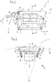
- Fig. 1 shows a mechanism 1 for an office chair in side view in the untwisted and not inclined state.
- Fig. 2 shows the mechanism 1 off Fig. 1 in a cross section along the line II-II.
- Fig. 3 shows the mechanism 1 off Fig. 2 with a laterally inclined seat support element.
- the mechanism 1 has a base support 2, which is set by means of a cone seat 3 on the upper end of a chair column (not shown).
- the mechanism 1 comprises a seat support 4, which is arranged on the base support 2 and is movable relative to the fixed base support 2 in the chair longitudinal direction 8 forwards and backwards.
- On the seat support 4 is usually provided with a padded seat seat (not shown) of the office chair mounted.
- the seat support 4 comprises a first seat support member 6 and a second seat support member 7, the second seat support member 7 being movable relative to the first seat support member 6 transversely to the chair longitudinal direction 8, i. to the right and left, is movable.
- the first seat support member 6 is the seat support base mounted separately from the actual seat, an element of the seat support 4 which cooperates with the base support 2.
- the second seat support member 7 is the seat mounting element, which either includes the seat with seat or - for example, designed as a mounting plate - provides the necessary conditions for a seat mounting.
- the mechanism 1 also includes a backrest support 5, the is connected to the seat support 4 and the base support 2. Connected to the backrest support 5 is the backrest (not shown) of the office chair, which as a rule is provided with a padded leaning surface.
- the backrest support 5 comprises a first backrest support element 9 and a second backrest support element 11, wherein the second backrest support element 11 is rotatable (tiltable) relative to the first backrest support element 8 about an axis of rotation 12 (inclination axis) lying in the chair longitudinal direction 8.
- the first backrest support member 9 is the backrest support base, an element of the backrest support 5, which cooperates with the base support.
- the second backrest support element 11 is the backrest mounting element, which either comprises the backrest with a support surface or - for example, designed as a mounting adapter - provides the necessary conditions for a backrest mounting.
- the backrest support 5 is pivotally connected both to the rear end 13 of the first seat support element 6 seen in the chair longitudinal direction 8 and to the rear end 14 of the base support 2 about transverse pivot axes 15, 16 extending transversely to the chair longitudinal direction 8, wherein the connecting region of the backrest support 5 between them both axes of rotation 15, 16 serves as a rear coupling element 17 between the base support 2 and seat support 4.
- a front coupling element 18 is pivotally connected both to the front longitudinal direction 21 of the base support 2 as viewed in the chair longitudinal direction 8 and to the front end 19 of the first seat support element 6 about front pivot axes 22, 23 extending transversely to the seat longitudinal direction 8.
- the manner in which the pivotable backrest support 5 is coupled to the first seat support element 6 and / or the base support 2 plays no role in the present invention. It can be a direct or an indirect coupling. The same applies to the articulation of the backrest support 5 to the base support 2 and the seat support 4 and thus the specific embodiment of the synchronous movement between the backrest and seat.
- the mechanism 1 is with respect to the central longitudinal plane 25 (see Fig. 2 ), which concerns the actual kinematics, constructed mirror-symmetrically. In that regard, in this description is always based on both sides pairwise existing construction elements of the mechanism 1. In the Fig. 2 and 3 Parts of the mechanism 1, in particular parts of the base support 2 are not shown for reasons of clarity.
- pivot movement, pivoting, pivot axis refer to the movement of the backrest support 5 and the seat support 4 about transverse to the chair longitudinal direction 8 extending axes of rotation 15, 16, 22, 23 at a pivoting of the backrest support 5.
- tilt movement, tilt "Tilting axis”, etc. refer to the movement of the second seat support member 7 and the second
- Backrest support member 11 extending in the chair longitudinal direction 8 axes of rotation 12, 33, 34, 35, 36 wherein the tilting movement may comprise a rotational and a translational component.
- tilting refers to the rotational part of the tilting movement.
- the chair longitudinal direction 8 extends from the front of the chair 26 in the direction of the chair back 27th
- the two seat support elements 6, 7 are arranged one above the other, in particular so that the second seat support member 7 is disposed on the first seat support member 6 and is disposed above the first seat support member 6 and is supported by the first seat support member 6.
- the transverse motion system according to the invention can be used without major structural adjustments with an already existing chair mechanism.
- a second seat support element 7 can be placed as an additional component on an existing mechanical component, wherein the seat support of the conventional mechanism forms the first seat support component 6 of the mechanism 1 according to the invention.
- the first seat support member 6 may be embodied as a mechanical component, which is hinged in a proven manner over transverse to the chair longitudinal direction 8 axes 22, 15 to the base support 2 and the backrest support 5.
- the first seat support member 6 may also be designed as a sliding in the chair longitudinal direction 8 seat slide; in this case, it may for example be suitable for seat depth adjustment.
- the second seat support member 7 is movable relative to the first seat support member 6 on a trajectory 28 which in a plane 29 is transverse to the chair longitudinal direction 8, wherein this plane 29 is preferably a vertical plane (see Fig. 1 ).
- the plane 29 may also be at an angle to the vertical.
- the seat carried by the second seat support element 7 in the chair longitudinal direction 8 tends to tilt laterally.
- the concrete embodiment of the seat is irrelevant to the invention.
- the tilting movement of the second seat support element 7 preferably comprises a translation and a rotation.
- a sideways movement ie a movement of the second seat support element 7 transversely to the chair longitudinal direction 8, combined with a tilting or tilting movement of the second seat support member 7 relative to the first seat support member 6.
- the second seat support member 7 is connected to the first seat support member 6 via at least one link assembly.
- the link assembly comprises two links 31, 32 (coupling elements), one of which is provided on each side of the vertical central longitudinal plane 25 of the chair.
- each link 31, 32 is pivotally connected both to a first axis of rotation 33, 35 rotatably mounted on the first seat support member 6 and about a second axis of rotation 34, 36 on the second seat support member 7, wherein all axes of rotation 33, 34, 35, 36 parallel to each other lie and in Chair longitudinal 8 run.
- all axes of rotation 33, 34, 35, 36 extend below the seat surface of the seat.
- connection of the two seat support elements 6, 7 takes place with the formation of a four-bar linkage, whereby for the second seat support element 7, a virtual pivot point 37 (instantaneous pole) results as the intersection of the two straight lines passing through the links 31, 32 (more precisely their articulation points). Due to the length of the links 31, 32 and / or the position of the articulation points or axes of rotation 33, 34, 35, 36 on the first and second seat support member 6, 7, the distance of the instantaneous pole 37 to the seat support 4 depending on the desired movement / inclination dynamics of the seat are defined.
- the links 31, 32 are designed in the illustrated example as a plate-shaped coupling elements, wherein the hinges for coupling to the first and second seat support member 6, 7 at the lower and upper side edge of the links 31, 32 are provided, so that the axes of rotation 33, 43 , 35, 36 extend parallel to the longitudinal direction of the links 31, 32.
- the number of links 31, 32 on each side of the central longitudinal plane 25 can also be greater. Thus, it is possible depending on the structural design, for example, that instead of a single link 31, 32 per side two or three links per page are provided.
- the instantaneous pole 37 is preferably located below the seat support 4, more precisely below the seat surface of the seat. At the in Fig. 18 illustrated variant, the instantaneous pole 37 is fixed as a real fulcrum in the seat support 4. There is no translation, only one tilting movement.
- the instantaneous pole 37 of the seat support 4 moves during a movement of the second Seat support member 7 transverse to the chair longitudinal direction 8 is always so far away from the seat support 4 that the translational components of the movement are greater than the rotational components.
- the instantaneous pole 37 is also preferably so far away from the seat support 4 that the translation component of the movement of the second seat support member 7 is greater than the rotation / inclination component of the movement.
- the second seat support member 7 does not move on any extremely curved or steep but rather on a rather flat trajectory. That benefits an increased seating comfort.
- the instantaneous pole 37 is close to the ground, ie in the vicinity of the chair support provided at the lower end of the chair column (not shown).
- the Momentanpol 37 moves, as in the Fig. 2 and 3 illustrated, with an inclination of the seat support 4 when using the handlebar assembly 31, 32 (four-bar mechanism) also on a trajectory 38 (see Fig. 3 ) and is not fixed. This is perceived as particularly pleasant for the dynamics of movement. In a pure tilting movement, as in Fig. 18 illustrated, the instantaneous pole 37 is fixed in place.
- the two links 31, 32 Defined by the position of the axes 33, 34, 35, 36 articulation points of the two links 31, 32 form (looking in chair longitudinal direction 8) in the non-deflected state a symmetrical, in particular isosceles trapezoid.
- the two links 31, 32 more precisely the connecting lines 41, 42 between the upper and lower articulation points (axial positions), the trapezoidal legs, the connecting line 43 between the upper articulation points, the upper trapezoid base side and the connecting line 44 between the lower articulation points, the lower trapezoidal base side ,
- the upper base side of the trapezoid is longer than the lower base side.
- spring elements which - acting at suitable locations - holds the second seat support element 7 in the non-inclined ground state in position relative to the first seat support element 6 and, in the inclined state, supports the return of the second seat support element 7 to its basic position . causes.
- spring elements are provided, which are connected on the one hand to the first seat support member 6 and the other on the second seat support member 7 or the handlebars 31, 32 to hold the second seat support member 7 in its not inclined to the right or left basic position.
- the second seat support member 7 is connected to the first seat support member 6 by the second seat support member 7 on a movement path of the second seat support member 7 defining surface 45 of the first seat support member 6 sliding ( Fig. 16 ) or rolling ( Fig. 17 ) rests, directly or indirectly, for example via ball bearings 46 or the like.
- the shape of the surface 45 defines the path of movement of the second Seat support member 7 transverse to the chair longitudinal direction 8. Even with the use of such a rolling or slideway a wandering instantaneous pole 37 can be achieved by the design of the surface 45 of the roll or slide.
- a convexly curved surface 45 of the first seat support element 6 acts in the direction of the second seat support element 7 with a concavely curved surface 47 of the second seat support element 7 in the direction of the first seat support element 6.
- first and second seat support members 6, 7 are two separate components which are mechanically interconnected, e.g. via the coupling elements described (handlebar 31, 32).
- at least one elastic coupling element may be arranged between the first and the second seat support element 6, 7 as a third component, for example in the form of a cuboid or cylindrical buffer element which ensures the required movability of the two seat support elements 6, 7 relative to one another.
- the buffer element is for example constructed so that between a base plate and a cover plate, a rubber-elastic material is arranged.
- Such or similar buffer elements can also be provided between the mutually movable mechanical components 6, 7, etc. as stop elements for limiting movement.
- the seat support elements 6, 7 (with or without buffer elements) is also a one-piece design of the two seat support members 6, 7 possible, preferably using suitable, flexible or elastic connecting material, the transverse movement and / or inclination of the second Seat support member 7 relative to the first seat support member 6 allowed.
- Such a variant is particularly advantageous to produce, for example using a multi-component injection molding process with various suitable plastics.
- the mechanical components are preferably constructed spring-back, that is to say in particular designed for returning the moved or deflected element to the basic position. The otherwise necessary spring elements for erecting the second seat support member 7 and for maintaining the state of equilibrium of the second seat support member 7 in the unoccupied state can then be eliminated.
- the movement of the second backrest support member 11 exclusively comprises a rotation.
- the required for the rotation of the backrest support member 11 central axis of rotation 12 (tilt axis) preferably extends below the seat surface of the seat.
- the axis of rotation 12 of the backrest support 5 extends in the chair longitudinal direction 8 and parallel to the axes of rotation 33, 34, 35, 36 of the link assembly 31, 32, and thus perpendicular to the axes of rotation 15, 16, 22, 23 of base support 2, seat support 4th and backrest support 5.
- the axis of rotation 12 in the vertical direction between the first axes of rotation 33, 35 of the links 31, 32 and the second axes of rotation 34, 36 of the links 31, 32 are arranged.
- the first and the second backrest support element 9, 11 are designed as two separate components, which are mechanically connected to each other, for example via a shock-side connection with rotational degree of freedom.
- a one-piece design of the two backrest support elements 9, 11 is possible, preferably using suitable, flexible or elastic Connecting material, which allows a rotation of the second backrest support member 11 about the rotation axis 12.
- the second backrest support element 11 is preferably designed as a central support arm, which extends centrally backwards away from the chair mechanism 1.
- the second backrest support element 11 is designed as part of a frame 50 for the backrest, for example as a central connecting element between the backrest support 5 and a lower transverse strut of the frame 50.
- the second backrest support member 11 is coupled to the second seat support member 7 such that movement of the second seat support member 7 relative to the first seat support member 6 moves the second back support member 11 relative to the first back support member 9, more specifically, tilting the second back support member 11 to the right left, causes (or vice versa).
- the seat tilts to the right or left
- the backrest A fixed backrest would be less comfortable with a reclining seat.
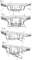
- the lateral inclination of the seat or the backrest (without a pivoting of the seat support 4 back through the backrest support 5) is in the Fig. 3 . 6 . 10 . 14 shown.
- the tilting movement of the backrest support 5, more precisely the tilting movement of the second backrest support element 11 and thus the backrest, is induced solely and exclusively by the articulation of the second backrest support element 11 to the second seat support element 7.
- the second seat support element 7 moves relative to the first seat support element 6 in the chair longitudinal direction 8
- a lateral inclination of the backrest carried by the second back support element 11 takes place.
- the concrete design of the backrest is irrelevant to the invention.
- the second backrest support member 11 is connected to the second seat support member 7 by a connecting arm 48 of the second backrest support member 11 engages with its free end 49 in a receiving opening 51 of the second seat support member 7 and rests in such a receiving opening 51.
- the initiation of the force or the transmission of the torque from the second seat support element 7 to the second backrest support element 11 takes place exclusively via the connecting arm 48.
- the connecting arm 48 is preferably not rotatably designed, i. the free end 49 is rotatably in the receiving opening 51 a.
- the free end 49 is both axial, i. in chair longitudinal direction 8, as well as vertically slidable in the receiving opening 51, so that the connecting arm 48 - according to the combined translation / rotational movement of the second seat support member 7 on the defined trajectory 28 relative to the first seat support member 6 - can move with limited degrees of freedom such in that it effects a (pure) rotational movement of the second backrest support element 11 about its axis of rotation 12 relative to the first backrest support element 9.
- This coupling is realized, for example, by a sliding block 52 or the like attached to the free end 49 of the connecting arm 48, which is in the manner of a groove formed in the scenery or receiving opening 51 of the second seat support member 7 (there fitting to the vertical side surfaces of the groove) rests.
- the movement of the gate and thus the movement of the second seat support elements 7 is transmitted to the positively driven sliding block 52, wherein the rotational degree of freedom is realized by a suitable rotational connection of the sliding block 52 with the connecting arm 48.
- the division of the backrest support 5 is carried out so that the first backrest support member 9 as seen in chair longitudinal direction 8 front part of the backrest support 5, the connection of the backrest to the base support 2 and the first seat support member 6 realized while the second backrest support member 11, which is in Guatemalalijnscardi 8 seen to the rear of the first backrest support member 9 connects, forms the transition to the backrest, but at the same time is coupled to the second seat support member 7.
- connection or coupling of the second seat support member 7 to the second backrest support member 11 via a number with the second seat support member 7 and the second backrest support member 11 articulated handlebar (not shown), which are preferably designed as the handlebar between the two seat support elements 6, 7 in the manner of a four-bar mechanism, or via other coupling elements.
- a variant has been found in which the inclination of the backrest or of the second backrest support element 11 is different from the inclination of the seat or of the second seat support element 7.
- the invention it is not only possible to realize only a tilting movement of the second seat support member 7 to the right or left, without this leading to a subsequent movement of the backrest support 5;
- only the coupling of the backrest support 5 to the second seat support element 7 must be omitted.
- the tilting movements of the elements involved can also differ from each other.
- the inclination of the second backrest support element 11 and thus the backrest corresponds to the inclination of the second seat support element 7 and thus of the seat.
- the backrest moves in a different relationship to the tilting seat, ie, the two tilt angles are unequal.
- An unequal inclination has been found to be particularly user-friendly, especially when an inclination of the second seat support member 7 by a certain inclination angle follows an inclination of the second seat back support member 11 by a larger inclination angle, as in the Fig. 6 . 10 and 14 shown.
- the position of the axis of rotation 12 of the backrest support 5 is below the connection point of the free end 49 of the connecting arm 48 with the seat support 4, ie below the point at which the sliding block 52 rests in the receiving opening 51.
- An opposing gift of the backrest can accordingly by a reverse arrangement of these two points to each other can be achieved.
- the desired tilt relationship between seat and backrest can be adjusted , In particular, by the structural arrangement of the position of the axes 33, 34, 35, 36, by the defined adjustment of the distances of the axes 33, 34, 35, 36 to each other and / or by the arrangement of the real and virtual pivot points 37 of the components involved Chair Mechanics 1.
- a variant of the invention in which the backrest support 5, more precisely the first backrest support member 9, with the seat support 4, more precisely with the first seat support member 6, coupled such that pivoting of the backrest support 5 in the chair longitudinal direction 8, a movement of the seat support 4 causes in the chair longitudinal direction 8 to a transverse to the chair longitudinal direction 8 pivot axis relative to the base support 2 ("synchronous mechanism").
- synchronous mechanism instead of such a classical synchronous mechanism, other types of mechanisms can be realized by the chair mechanism 1, which is provided with the invention, such as asynchronous mechanisms, luffing mechanisms or mixed types.
- the (tilting) movement of the second seat support element 7 relative to the first seat support element 6 is independent of any other movement of the seat support 4 in the chair longitudinal direction 8, in particular independent of the (5) caused by the backrest support (pivot) movement of the seat support 4. Achieved this constructive and functional independence of the movements by the separation of the seat support 4 in the two seat support members 6, 7. Both movements are independent of each other, that is not coupled to each other, possible, even superimposed on each other.
- the entire seat support 4 is carried along when pivoting the backrest support 5 to the rear and a tilting movement of the second seat support member 7 to the right and left can in pronounceverschwenkten state of the mechanism 1 or in addition to pivoting the backrest done.
- FIG. 4 to 15 This is illustrated by way of example in the Fig. 4 to 15 with reference to the first embodiment.
- Fig. 4 to 7 the mechanics in side view, namely in the starting position ( Fig. 4 ), pivoted backwards ( Fig. 5 ), with laterally inclined seat and backrest ( Fig. 6 ) as well as in an inclined as well as a pivoted position ( Fig. 7 ).
- Fig. 4 to 7 the mechanics in side view, namely in the starting position ( Fig. 4 ), pivoted backwards ( Fig. 5 ), with laterally inclined seat and backrest ( Fig. 6 ) as well as in an inclined as well as a pivoted position ( Fig. 7 ).
- the invention Compared to a conventional chair mechanism, the invention increases the number of degrees of freedom by providing more degrees of freedom for the seat support 4 and optionally also for the backrest support 5. It results over conventional solutions improved movement behavior of the chair to movements of the user. All in the description, the following claims and the drawings illustrated features may be essential to the invention both individually and in any combination.
Landscapes
- Health & Medical Sciences (AREA)
- Dentistry (AREA)
- General Health & Medical Sciences (AREA)
- Chairs Characterized By Structure (AREA)
- Chairs For Special Purposes, Such As Reclining Chairs (AREA)
Applications Claiming Priority (2)
| Application Number | Priority Date | Filing Date | Title |
|---|---|---|---|
| DE102017100117 | 2017-01-04 | ||
| DE202017102909.3U DE202017102909U1 (de) | 2017-01-04 | 2017-05-15 | Stuhl mit einteiliger Sitzschale |
Publications (2)
| Publication Number | Publication Date |
|---|---|
| EP3345507A1 true EP3345507A1 (fr) | 2018-07-11 |
| EP3345507B1 EP3345507B1 (fr) | 2020-04-29 |
Family
ID=62026929
Family Applications (2)
| Application Number | Title | Priority Date | Filing Date |
|---|---|---|---|
| EP18150177.6A Active EP3345508B1 (fr) | 2017-01-04 | 2018-01-03 | Chaise à coque en une seule pièce |
| EP18000037.4A Not-in-force EP3345507B1 (fr) | 2017-01-04 | 2018-01-04 | Mécanisme pour une chaise |
Family Applications Before (1)
| Application Number | Title | Priority Date | Filing Date |
|---|---|---|---|
| EP18150177.6A Active EP3345508B1 (fr) | 2017-01-04 | 2018-01-03 | Chaise à coque en une seule pièce |
Country Status (3)
| Country | Link |
|---|---|
| US (1) | US10499742B2 (fr) |
| EP (2) | EP3345508B1 (fr) |
| DE (1) | DE202017102909U1 (fr) |
Cited By (2)
| Publication number | Priority date | Publication date | Assignee | Title |
|---|---|---|---|---|
| US10881208B2 (en) * | 2016-02-23 | 2021-01-05 | Kokuyo Co., Ltd. | Chair and seat support mechanism |
| DE102020124975A1 (de) | 2020-09-24 | 2022-03-24 | Bock 1 Gmbh & Co. Kg | Mechanik für einen Stuhl |
Families Citing this family (2)
| Publication number | Priority date | Publication date | Assignee | Title |
|---|---|---|---|---|
| US10702066B2 (en) * | 2018-11-19 | 2020-07-07 | Profim SP. ZO.O | Office chair |
| US12582232B2 (en) | 2021-05-04 | 2026-03-24 | Moovlab Inc. | Ergonomic motion chair |
Citations (4)
| Publication number | Priority date | Publication date | Assignee | Title |
|---|---|---|---|---|
| DE202012012606U1 (de) * | 2011-05-04 | 2013-06-12 | Eckhard Hansen | Sitzmöbel |
| DE102012107778A1 (de) * | 2012-08-23 | 2014-06-26 | Haworth Gmbh | Stuhl, insbesondere Bürostuhl |
| DE202014101592U1 (de) * | 2014-04-04 | 2014-06-30 | Wilkhahn Wilkening + Hahne Gmbh + Co. | Stuhl |
| DE102014103780B3 (de) * | 2014-03-19 | 2015-06-18 | Wilkhahn Wilkening + Hahne Gmbh + Co. | Stuhl |
Family Cites Families (11)
| Publication number | Priority date | Publication date | Assignee | Title |
|---|---|---|---|---|
| CH666171A5 (de) * | 1984-10-03 | 1988-07-15 | Giroflex Entwicklungs Ag | Stuhl mit rueckwaerts neigbarem sitz- und rueckenlehnentraeger. |
| US5538326A (en) * | 1994-11-14 | 1996-07-23 | Milsco Manufacturing Company | Flexible unitary seat shell |
| MXPA01012487A (es) * | 1999-06-17 | 2002-06-04 | Steelcase Inc | Construccion de silla. |
| DE10106791A1 (de) * | 2001-02-12 | 2002-08-14 | Sdm Hansen Gmbh St Margrethen | Sitzmöbel |
| ITMI20022194A1 (it) * | 2002-10-16 | 2004-04-17 | Icf Spa | Sedia avente sedile e schienale mobili. |
| WO2007110732A2 (fr) * | 2006-03-24 | 2007-10-04 | Herman Miller Inc. | Meuble |
| DE102008011309B3 (de) * | 2008-02-27 | 2009-06-04 | Thonet Gmbh | Bürostuhl |
| NO328092B1 (no) * | 2008-03-10 | 2009-12-07 | Efg Europ Furniture Group Ab | Ryggestotteanordning |
| DE202012002288U1 (de) * | 2012-03-08 | 2012-05-11 | Walter Knoll Ag & Co. Kg | Funktionsstuhl |
| WO2014061299A1 (fr) * | 2012-10-18 | 2014-04-24 | 株式会社岡村製作所 | Chaise |
| DE102014119612A1 (de) * | 2014-12-23 | 2016-06-23 | Recaro Aircraft Seating Gmbh & Co. Kg | Sitzvorrichtung mit längsgeteilter Sitzbodeneinheit |
-
2017
- 2017-05-15 DE DE202017102909.3U patent/DE202017102909U1/de not_active Expired - Lifetime
-
2018
- 2018-01-03 EP EP18150177.6A patent/EP3345508B1/fr active Active
- 2018-01-04 EP EP18000037.4A patent/EP3345507B1/fr not_active Not-in-force
- 2018-01-04 US US15/861,714 patent/US10499742B2/en active Active
Patent Citations (4)
| Publication number | Priority date | Publication date | Assignee | Title |
|---|---|---|---|---|
| DE202012012606U1 (de) * | 2011-05-04 | 2013-06-12 | Eckhard Hansen | Sitzmöbel |
| DE102012107778A1 (de) * | 2012-08-23 | 2014-06-26 | Haworth Gmbh | Stuhl, insbesondere Bürostuhl |
| DE102014103780B3 (de) * | 2014-03-19 | 2015-06-18 | Wilkhahn Wilkening + Hahne Gmbh + Co. | Stuhl |
| DE202014101592U1 (de) * | 2014-04-04 | 2014-06-30 | Wilkhahn Wilkening + Hahne Gmbh + Co. | Stuhl |
Cited By (3)
| Publication number | Priority date | Publication date | Assignee | Title |
|---|---|---|---|---|
| US10881208B2 (en) * | 2016-02-23 | 2021-01-05 | Kokuyo Co., Ltd. | Chair and seat support mechanism |
| DE102020124975A1 (de) | 2020-09-24 | 2022-03-24 | Bock 1 Gmbh & Co. Kg | Mechanik für einen Stuhl |
| EP3973820A1 (fr) | 2020-09-24 | 2022-03-30 | BOCK 1 GmbH & Co. KG | Mécanisme pour une chaise |
Also Published As
| Publication number | Publication date |
|---|---|
| DE202017102909U1 (de) | 2018-04-05 |
| US20180184809A1 (en) | 2018-07-05 |
| EP3345508B1 (fr) | 2020-06-17 |
| US10499742B2 (en) | 2019-12-10 |
| EP3345508A1 (fr) | 2018-07-11 |
| EP3345507B1 (fr) | 2020-04-29 |
Similar Documents
| Publication | Publication Date | Title |
|---|---|---|
| EP1946676B1 (fr) | Chaise | |
| DE19646470B4 (de) | Kraftfahrzeugsitz mit einer Lehne und einem Sitz | |
| DE102015101546B4 (de) | Synchronmechanik | |
| EP2801293B1 (fr) | Elément de siège et sa garniture | |
| EP1060694A1 (fr) | Chaise, notamment chaise de bureau | |
| EP3345507B1 (fr) | Mécanisme pour une chaise | |
| WO2011141107A1 (fr) | Mécanisme de réglage d'une force de rappel agissant sur le dossier d'un siège et siège de bureau doté d'un mécanisme de ce type | |
| AT12867U1 (de) | Sitzmöbel | |
| EP3120732B1 (fr) | Mecanisme de siege de bureau | |
| DE102019215769A1 (de) | Sitzträgerstruktur für einen Fahrzeugsitz | |
| WO2016124317A1 (fr) | Mecanisme synchrone | |
| EP3387957A1 (fr) | Mécanique synchrone pour un siège de bureau | |
| EP3528664A1 (fr) | Mécanisme synchronisé pour chaise et chaise comprenant un tel mécanisme | |
| EP3973820A1 (fr) | Mécanisme pour une chaise | |
| EP1652505B1 (fr) | Fauteuil de traitement, en particulier fauteuil de traitement dentaire | |
| WO2006074763A1 (fr) | Meuble, en particulier meuble d'assise | |
| EP1992255A1 (fr) | Meubles destinés à s'asseoir | |
| EP2477523B1 (fr) | Mécanisme de bascule pour une chaise de bureau | |
| DE102019113582B4 (de) | Synchronmechanik | |
| EP2994017B1 (fr) | Mécanique synchrone | |
| EP3437519B1 (fr) | Mécanisme basculant | |
| EP3253254B1 (fr) | Mecanisme synchrone | |
| EP3253255B1 (fr) | Mecanisme synchrone | |
| DE102019113581A1 (de) | Synchronmechanik | |
| DE102024129797A1 (de) | Mechanik für ein Sitzmöbel, insbesondere für einen Bürostuhl |
Legal Events
| Date | Code | Title | Description |
|---|---|---|---|
| PUAI | Public reference made under article 153(3) epc to a published international application that has entered the european phase |
Free format text: ORIGINAL CODE: 0009012 |
|
| STAA | Information on the status of an ep patent application or granted ep patent |
Free format text: STATUS: THE APPLICATION HAS BEEN PUBLISHED |
|
| AK | Designated contracting states |
Kind code of ref document: A1 Designated state(s): AL AT BE BG CH CY CZ DE DK EE ES FI FR GB GR HR HU IE IS IT LI LT LU LV MC MK MT NL NO PL PT RO RS SE SI SK SM TR |
|
| AX | Request for extension of the european patent |
Extension state: BA ME |
|
| STAA | Information on the status of an ep patent application or granted ep patent |
Free format text: STATUS: REQUEST FOR EXAMINATION WAS MADE |
|
| 17P | Request for examination filed |
Effective date: 20181219 |
|
| RBV | Designated contracting states (corrected) |
Designated state(s): AL AT BE BG CH CY CZ DE DK EE ES FI FR GB GR HR HU IE IS IT LI LT LU LV MC MK MT NL NO PL PT RO RS SE SI SK SM TR |
|
| STAA | Information on the status of an ep patent application or granted ep patent |
Free format text: STATUS: EXAMINATION IS IN PROGRESS |
|
| 17Q | First examination report despatched |
Effective date: 20190301 |
|
| GRAP | Despatch of communication of intention to grant a patent |
Free format text: ORIGINAL CODE: EPIDOSNIGR1 |
|
| STAA | Information on the status of an ep patent application or granted ep patent |
Free format text: STATUS: GRANT OF PATENT IS INTENDED |
|
| INTG | Intention to grant announced |
Effective date: 20191212 |
|
| GRAS | Grant fee paid |
Free format text: ORIGINAL CODE: EPIDOSNIGR3 |
|
| GRAA | (expected) grant |
Free format text: ORIGINAL CODE: 0009210 |
|
| STAA | Information on the status of an ep patent application or granted ep patent |
Free format text: STATUS: THE PATENT HAS BEEN GRANTED |
|
| AK | Designated contracting states |
Kind code of ref document: B1 Designated state(s): AL AT BE BG CH CY CZ DE DK EE ES FI FR GB GR HR HU IE IS IT LI LT LU LV MC MK MT NL NO PL PT RO RS SE SI SK SM TR |
|
| REG | Reference to a national code |
Ref country code: GB Ref legal event code: FG4D Free format text: NOT ENGLISH |
|
| REG | Reference to a national code |
Ref country code: CH Ref legal event code: EP |
|
| REG | Reference to a national code |
Ref country code: DE Ref legal event code: R096 Ref document number: 502018001277 Country of ref document: DE |
|
| REG | Reference to a national code |
Ref country code: AT Ref legal event code: REF Ref document number: 1262029 Country of ref document: AT Kind code of ref document: T Effective date: 20200515 |
|
| REG | Reference to a national code |
Ref country code: IE Ref legal event code: FG4D Free format text: LANGUAGE OF EP DOCUMENT: GERMAN |
|
| REG | Reference to a national code |
Ref country code: NL Ref legal event code: MP Effective date: 20200429 |
|
| REG | Reference to a national code |
Ref country code: LT Ref legal event code: MG4D |
|
| PG25 | Lapsed in a contracting state [announced via postgrant information from national office to epo] |
Ref country code: GR Free format text: LAPSE BECAUSE OF FAILURE TO SUBMIT A TRANSLATION OF THE DESCRIPTION OR TO PAY THE FEE WITHIN THE PRESCRIBED TIME-LIMIT Effective date: 20200730 Ref country code: SE Free format text: LAPSE BECAUSE OF FAILURE TO SUBMIT A TRANSLATION OF THE DESCRIPTION OR TO PAY THE FEE WITHIN THE PRESCRIBED TIME-LIMIT Effective date: 20200429 Ref country code: PT Free format text: LAPSE BECAUSE OF FAILURE TO SUBMIT A TRANSLATION OF THE DESCRIPTION OR TO PAY THE FEE WITHIN THE PRESCRIBED TIME-LIMIT Effective date: 20200831 Ref country code: LT Free format text: LAPSE BECAUSE OF FAILURE TO SUBMIT A TRANSLATION OF THE DESCRIPTION OR TO PAY THE FEE WITHIN THE PRESCRIBED TIME-LIMIT Effective date: 20200429 Ref country code: FI Free format text: LAPSE BECAUSE OF FAILURE TO SUBMIT A TRANSLATION OF THE DESCRIPTION OR TO PAY THE FEE WITHIN THE PRESCRIBED TIME-LIMIT Effective date: 20200429 Ref country code: IS Free format text: LAPSE BECAUSE OF FAILURE TO SUBMIT A TRANSLATION OF THE DESCRIPTION OR TO PAY THE FEE WITHIN THE PRESCRIBED TIME-LIMIT Effective date: 20200829 Ref country code: NO Free format text: LAPSE BECAUSE OF FAILURE TO SUBMIT A TRANSLATION OF THE DESCRIPTION OR TO PAY THE FEE WITHIN THE PRESCRIBED TIME-LIMIT Effective date: 20200729 |
|
| REG | Reference to a national code |
Ref country code: CH Ref legal event code: PK Free format text: BERICHTIGUNGEN |
|
| PG25 | Lapsed in a contracting state [announced via postgrant information from national office to epo] |
Ref country code: RS Free format text: LAPSE BECAUSE OF FAILURE TO SUBMIT A TRANSLATION OF THE DESCRIPTION OR TO PAY THE FEE WITHIN THE PRESCRIBED TIME-LIMIT Effective date: 20200429 Ref country code: HR Free format text: LAPSE BECAUSE OF FAILURE TO SUBMIT A TRANSLATION OF THE DESCRIPTION OR TO PAY THE FEE WITHIN THE PRESCRIBED TIME-LIMIT Effective date: 20200429 Ref country code: LV Free format text: LAPSE BECAUSE OF FAILURE TO SUBMIT A TRANSLATION OF THE DESCRIPTION OR TO PAY THE FEE WITHIN THE PRESCRIBED TIME-LIMIT Effective date: 20200429 Ref country code: BG Free format text: LAPSE BECAUSE OF FAILURE TO SUBMIT A TRANSLATION OF THE DESCRIPTION OR TO PAY THE FEE WITHIN THE PRESCRIBED TIME-LIMIT Effective date: 20200729 |
|
| RIN2 | Information on inventor provided after grant (corrected) |
Inventor name: BOCK, HERMANN Inventor name: BALLENDAT, MARTIN |
|
| PG25 | Lapsed in a contracting state [announced via postgrant information from national office to epo] |
Ref country code: AL Free format text: LAPSE BECAUSE OF FAILURE TO SUBMIT A TRANSLATION OF THE DESCRIPTION OR TO PAY THE FEE WITHIN THE PRESCRIBED TIME-LIMIT Effective date: 20200429 Ref country code: NL Free format text: LAPSE BECAUSE OF FAILURE TO SUBMIT A TRANSLATION OF THE DESCRIPTION OR TO PAY THE FEE WITHIN THE PRESCRIBED TIME-LIMIT Effective date: 20200429 |
|
| PG25 | Lapsed in a contracting state [announced via postgrant information from national office to epo] |
Ref country code: ES Free format text: LAPSE BECAUSE OF FAILURE TO SUBMIT A TRANSLATION OF THE DESCRIPTION OR TO PAY THE FEE WITHIN THE PRESCRIBED TIME-LIMIT Effective date: 20200429 Ref country code: DK Free format text: LAPSE BECAUSE OF FAILURE TO SUBMIT A TRANSLATION OF THE DESCRIPTION OR TO PAY THE FEE WITHIN THE PRESCRIBED TIME-LIMIT Effective date: 20200429 Ref country code: SM Free format text: LAPSE BECAUSE OF FAILURE TO SUBMIT A TRANSLATION OF THE DESCRIPTION OR TO PAY THE FEE WITHIN THE PRESCRIBED TIME-LIMIT Effective date: 20200429 Ref country code: EE Free format text: LAPSE BECAUSE OF FAILURE TO SUBMIT A TRANSLATION OF THE DESCRIPTION OR TO PAY THE FEE WITHIN THE PRESCRIBED TIME-LIMIT Effective date: 20200429 Ref country code: CZ Free format text: LAPSE BECAUSE OF FAILURE TO SUBMIT A TRANSLATION OF THE DESCRIPTION OR TO PAY THE FEE WITHIN THE PRESCRIBED TIME-LIMIT Effective date: 20200429 Ref country code: RO Free format text: LAPSE BECAUSE OF FAILURE TO SUBMIT A TRANSLATION OF THE DESCRIPTION OR TO PAY THE FEE WITHIN THE PRESCRIBED TIME-LIMIT Effective date: 20200429 |
|
| REG | Reference to a national code |
Ref country code: DE Ref legal event code: R097 Ref document number: 502018001277 Country of ref document: DE |
|
| PG25 | Lapsed in a contracting state [announced via postgrant information from national office to epo] |
Ref country code: SK Free format text: LAPSE BECAUSE OF FAILURE TO SUBMIT A TRANSLATION OF THE DESCRIPTION OR TO PAY THE FEE WITHIN THE PRESCRIBED TIME-LIMIT Effective date: 20200429 Ref country code: PL Free format text: LAPSE BECAUSE OF FAILURE TO SUBMIT A TRANSLATION OF THE DESCRIPTION OR TO PAY THE FEE WITHIN THE PRESCRIBED TIME-LIMIT Effective date: 20200429 |
|
| PLBE | No opposition filed within time limit |
Free format text: ORIGINAL CODE: 0009261 |
|
| STAA | Information on the status of an ep patent application or granted ep patent |
Free format text: STATUS: NO OPPOSITION FILED WITHIN TIME LIMIT |
|
| 26N | No opposition filed |
Effective date: 20210201 |
|
| PG25 | Lapsed in a contracting state [announced via postgrant information from national office to epo] |
Ref country code: SI Free format text: LAPSE BECAUSE OF FAILURE TO SUBMIT A TRANSLATION OF THE DESCRIPTION OR TO PAY THE FEE WITHIN THE PRESCRIBED TIME-LIMIT Effective date: 20200429 |
|
| PG25 | Lapsed in a contracting state [announced via postgrant information from national office to epo] |
Ref country code: MC Free format text: LAPSE BECAUSE OF FAILURE TO SUBMIT A TRANSLATION OF THE DESCRIPTION OR TO PAY THE FEE WITHIN THE PRESCRIBED TIME-LIMIT Effective date: 20200429 |
|
| REG | Reference to a national code |
Ref country code: CH Ref legal event code: PL |
|
| PG25 | Lapsed in a contracting state [announced via postgrant information from national office to epo] |
Ref country code: LU Free format text: LAPSE BECAUSE OF NON-PAYMENT OF DUE FEES Effective date: 20210104 |
|
| REG | Reference to a national code |
Ref country code: BE Ref legal event code: MM Effective date: 20210131 |
|
| PG25 | Lapsed in a contracting state [announced via postgrant information from national office to epo] |
Ref country code: FR Free format text: LAPSE BECAUSE OF NON-PAYMENT OF DUE FEES Effective date: 20210131 |
|
| PG25 | Lapsed in a contracting state [announced via postgrant information from national office to epo] |
Ref country code: LI Free format text: LAPSE BECAUSE OF NON-PAYMENT OF DUE FEES Effective date: 20210131 Ref country code: CH Free format text: LAPSE BECAUSE OF NON-PAYMENT OF DUE FEES Effective date: 20210131 |
|
| PG25 | Lapsed in a contracting state [announced via postgrant information from national office to epo] |
Ref country code: IE Free format text: LAPSE BECAUSE OF NON-PAYMENT OF DUE FEES Effective date: 20210104 |
|
| PG25 | Lapsed in a contracting state [announced via postgrant information from national office to epo] |
Ref country code: BE Free format text: LAPSE BECAUSE OF NON-PAYMENT OF DUE FEES Effective date: 20210131 |
|
| PG25 | Lapsed in a contracting state [announced via postgrant information from national office to epo] |
Ref country code: CY Free format text: LAPSE BECAUSE OF FAILURE TO SUBMIT A TRANSLATION OF THE DESCRIPTION OR TO PAY THE FEE WITHIN THE PRESCRIBED TIME-LIMIT Effective date: 20200429 |
|
| PG25 | Lapsed in a contracting state [announced via postgrant information from national office to epo] |
Ref country code: HU Free format text: LAPSE BECAUSE OF FAILURE TO SUBMIT A TRANSLATION OF THE DESCRIPTION OR TO PAY THE FEE WITHIN THE PRESCRIBED TIME-LIMIT; INVALID AB INITIO Effective date: 20180104 |
|
| PGFP | Annual fee paid to national office [announced via postgrant information from national office to epo] |
Ref country code: GB Payment date: 20231128 Year of fee payment: 7 |
|
| REG | Reference to a national code |
Ref country code: AT Ref legal event code: MM01 Ref document number: 1262029 Country of ref document: AT Kind code of ref document: T Effective date: 20230104 |
|
| PG25 | Lapsed in a contracting state [announced via postgrant information from national office to epo] |
Ref country code: AT Free format text: LAPSE BECAUSE OF NON-PAYMENT OF DUE FEES Effective date: 20230104 |
|
| PG25 | Lapsed in a contracting state [announced via postgrant information from national office to epo] |
Ref country code: MK Free format text: LAPSE BECAUSE OF FAILURE TO SUBMIT A TRANSLATION OF THE DESCRIPTION OR TO PAY THE FEE WITHIN THE PRESCRIBED TIME-LIMIT Effective date: 20200429 Ref country code: AT Free format text: LAPSE BECAUSE OF NON-PAYMENT OF DUE FEES Effective date: 20230104 |
|
| PGFP | Annual fee paid to national office [announced via postgrant information from national office to epo] |
Ref country code: DE Payment date: 20240111 Year of fee payment: 7 |
|
| PGFP | Annual fee paid to national office [announced via postgrant information from national office to epo] |
Ref country code: IT Payment date: 20231205 Year of fee payment: 7 |
|
| PG25 | Lapsed in a contracting state [announced via postgrant information from national office to epo] |
Ref country code: MT Free format text: LAPSE BECAUSE OF FAILURE TO SUBMIT A TRANSLATION OF THE DESCRIPTION OR TO PAY THE FEE WITHIN THE PRESCRIBED TIME-LIMIT Effective date: 20200429 |
|
| REG | Reference to a national code |
Ref country code: DE Ref legal event code: R119 Ref document number: 502018001277 Country of ref document: DE |
|
| GBPC | Gb: european patent ceased through non-payment of renewal fee |
Effective date: 20250104 |
|
| PG25 | Lapsed in a contracting state [announced via postgrant information from national office to epo] |
Ref country code: DE Free format text: LAPSE BECAUSE OF NON-PAYMENT OF DUE FEES Effective date: 20250801 |
|
| PG25 | Lapsed in a contracting state [announced via postgrant information from national office to epo] |
Ref country code: GB Free format text: LAPSE BECAUSE OF NON-PAYMENT OF DUE FEES Effective date: 20250104 |
|
| PG25 | Lapsed in a contracting state [announced via postgrant information from national office to epo] |
Ref country code: TR Free format text: LAPSE BECAUSE OF FAILURE TO SUBMIT A TRANSLATION OF THE DESCRIPTION OR TO PAY THE FEE WITHIN THE PRESCRIBED TIME-LIMIT Effective date: 20200429 |
|
| PG25 | Lapsed in a contracting state [announced via postgrant information from national office to epo] |
Ref country code: IT Free format text: LAPSE BECAUSE OF NON-PAYMENT OF DUE FEES Effective date: 20250104 |
|
| PGFP | Annual fee paid to national office [announced via postgrant information from national office to epo] |
Ref country code: AT Payment date: 20260410 Year of fee payment: 5 |