EP3345512A1 - Montant de rayonnage et système de rayonnage réglable - Google Patents
Montant de rayonnage et système de rayonnage réglable Download PDFInfo
- Publication number
- EP3345512A1 EP3345512A1 EP17150317.0A EP17150317A EP3345512A1 EP 3345512 A1 EP3345512 A1 EP 3345512A1 EP 17150317 A EP17150317 A EP 17150317A EP 3345512 A1 EP3345512 A1 EP 3345512A1
- Authority
- EP
- European Patent Office
- Prior art keywords
- vertically extending
- extending member
- shelving
- post
- shelf
- Prior art date
- Legal status (The legal status is an assumption and is not a legal conclusion. Google has not performed a legal analysis and makes no representation as to the accuracy of the status listed.)
- Withdrawn
Links
- 229910000831 Steel Inorganic materials 0.000 description 4
- 239000010959 steel Substances 0.000 description 4
- 210000003195 fascia Anatomy 0.000 description 3
- 238000004026 adhesive bonding Methods 0.000 description 1
- 230000037431 insertion Effects 0.000 description 1
- 238000003780 insertion Methods 0.000 description 1
- 230000014759 maintenance of location Effects 0.000 description 1
- 239000000463 material Substances 0.000 description 1
Images



Classifications
-
- A—HUMAN NECESSITIES
- A47—FURNITURE; DOMESTIC ARTICLES OR APPLIANCES; COFFEE MILLS; SPICE MILLS; SUCTION CLEANERS IN GENERAL
- A47B—TABLES; DESKS; OFFICE FURNITURE; CABINETS; DRAWERS; GENERAL DETAILS OF FURNITURE
- A47B96/00—Details of cabinets, racks or shelf units not covered by a single one of groups A47B43/00 - A47B95/00; General details of furniture
- A47B96/14—Bars, uprights, struts, or like supports, for cabinets, brackets, or the like
- A47B96/1416—Uprights receiving panels and brackets
-
- A—HUMAN NECESSITIES
- A47—FURNITURE; DOMESTIC ARTICLES OR APPLIANCES; COFFEE MILLS; SPICE MILLS; SUCTION CLEANERS IN GENERAL
- A47B—TABLES; DESKS; OFFICE FURNITURE; CABINETS; DRAWERS; GENERAL DETAILS OF FURNITURE
- A47B57/00—Cabinets, racks or shelf units, characterised by features for adjusting shelves or partitions
- A47B57/06—Cabinets, racks or shelf units, characterised by features for adjusting shelves or partitions with means for adjusting the height of the shelves
- A47B57/16—Cabinets, racks or shelf units, characterised by features for adjusting shelves or partitions with means for adjusting the height of the shelves consisting of hooks coacting with openings
-
- A—HUMAN NECESSITIES
- A47—FURNITURE; DOMESTIC ARTICLES OR APPLIANCES; COFFEE MILLS; SPICE MILLS; SUCTION CLEANERS IN GENERAL
- A47F—SPECIAL FURNITURE, FITTINGS, OR ACCESSORIES FOR SHOPS, STOREHOUSES, BARS, RESTAURANTS OR THE LIKE; PAYING COUNTERS
- A47F5/00—Show stands, hangers, or shelves characterised by their constructional features
- A47F5/10—Adjustable or foldable or dismountable display stands
- A47F5/101—Display racks with slotted uprights
-
- A—HUMAN NECESSITIES
- A47—FURNITURE; DOMESTIC ARTICLES OR APPLIANCES; COFFEE MILLS; SPICE MILLS; SUCTION CLEANERS IN GENERAL
- A47F—SPECIAL FURNITURE, FITTINGS, OR ACCESSORIES FOR SHOPS, STOREHOUSES, BARS, RESTAURANTS OR THE LIKE; PAYING COUNTERS
- A47F5/00—Show stands, hangers, or shelves characterised by their constructional features
- A47F5/10—Adjustable or foldable or dismountable display stands
- A47F5/101—Display racks with slotted uprights
- A47F5/103—Display shelving racks with the uprights aligned in only one plane
Definitions
- the invention relates to shelving posts utilised in adjustable shelving systems. More specifically the invention relates to improved shelving systems for displaying product in retail environments and in particular, supermarkets and other such stores.
- Retail environments such as supermarkets employ shelving systems for displaying merchandise for sale. Due to the ever changing nature of products sold by stores, shelving systems employing adjustable shelving systems are the dominant and most common type of shelving systems used in this area. This is because a retailer may wish to reconfigure one or more sections of the shelves to accommodate products that would otherwise not fit in the pre-existing shelving fit out.
- Adjustable shelves often are supported by a single pair of shelving posts which differentiate them from those shelving systems that incorporate four posts and rectangular shelves attached to all four posts.
- the utilisation of just a single pair of posts at the rear of the shelves allow for more unimpeded access to the products on the shelves.
- a shelving post for use in supporting a shelf of an adjustable shelving system characterised in that the shelving post comprises:
- the second vertically extending member extends perpendicularly from the first vertically extending member.
- the vertically extending members are planar.
- first and second support surfaces of the first vertically extending member are coplanar and the second vertically extending member is planar.
- first and second support surfaces of the first vertically extending member are planar and the first vertically extending member further comprises at least one projecting member that extends rearwardly from the coplanar first and second support surfaces.
- the at least one rearwardly projecting member comprises two rearwardly projecting members extending rearwardly in a parallel plane as the second vertically extending member.
- the shelving post further comprises a horizontal leg support which is connected to the first and second vertically extending members and wherein at least a lower portion of the second vertically extending member is connected along its length to the horizontal leg support.
- the horizontal leg support has an upwardly projecting horizontal member which abuts the lower portion of the second vertically extending member.
- the second vertically extending member extends perpendicularly from the first vertically extending member.
- the first vertically extending member is planar.
- first and second support surfaces of the first vertically extending member and second vertically extending member are planar.
- first and second support surfaces of the first vertically extending member are coplanar and the first vertically extending member further comprises at least one projecting member that extends rearwardly from the coplanar first and second support surfaces.
- the at least one rearwardly projecting member comprises two rearwardly projecting members extending rearwardly in a parallel plane with the second vertically extending member.
- the shelving post further comprises a horizontal leg support which is connected to the first and second vertically extending members and wherein at least a lower portion of the second vertically extending member is connected along its length to the horizontal leg support.
- the horizontal leg support has an upwardly projecting horizontal member which abuts the lower portion of the second vertically extending member.
- Fig. 1 depicts a prior art shelving system 10.
- the shelving system 10 suffers from the problems set out in the background to the invention.
- it features large posts 12 which support two horizontal supports 14 which in turn support shelf or rack 16.
- Due to the width and depth of the posts 12 the width of the rear of shelf or rack 18 is significantly narrower than the width of the front of the shelf or rack 20.
- prior art posts are not only wide but often deep, the impacted area of the shelf can be significant as the retailer cannot merchandise product all the way to the edge of the posts.
- the size of the posts usually results in the retailer avoiding placing lines of goods stacked from front to rear in the portions of the rack or shelf 16 that are in front of the posts 12, or if product is placed in those portions, a reduced number of products is able to be placed in these positions.
- Figs 2 to 6 depict a shelving post 22 according to a first embodiment of a first aspect of the invention.
- the shelving post 22 when incorporated into a shelving system, obviates or significantly reduces the problems associated with prior art shelving systems. It does this by dispensing with RHS or SHS shaped vertical members and replacing it with a vertical member that has a planar protrusion or fin 24 that provides structural support whilst at the same time, minimises the width and depth of the remaining elements that make up the post 22, thereby minimising the usual dead space associated with prior art posts 12.
- the post 22 also features a low profile rear support comprising front facing surface 26 and lug guard 28.
- the front facing surface has apertures 30 either side of fin 24 through which lugs on the shelf arms are supported and maintained for holding the shelf.
- Lug guards 28 are preferably utilised so as to prevent the shelf post from being pressed up against a wall thereby causing the inserted lugs from being dislodged.
- the post 22 may be simply comprised of front facing surface 26 and fin 24 which forms a simple T shape.
- the post 22 also has horizontal leg portion 32 which is in turn comprised of a leg fin 34 mounted upon a planar leg base 36. The fin 24 and leg fin 34 abut each other to provide further structural support.
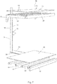
- FIGs. 7 and 8 depict a first embodiment of the second aspect of the invention there is depicted shelving system 40 which incorporates post 22 of Figs. 2 to 6 .
- the system is depicted with one post 22 in Fig 7 for simplicity however when assembled, as depicted in Fig. 8 , two posts 22 are utilised in the provision of adjustable shelving.
- the components of shelving system 40 include bracing members 42 which are made from roll formed steel in a U shape with an open bottom and a planar top surface 44.
- the bracing members 42 further feature downwardly projecting tabs 46 which are adapted to extend over and be secured on leg fin 34.
- bracing members When bracing members are fitted over the leg fins 34 of two posts the top surfaces 44 create a flat surface for the support of a shelving surface 48 which can be fixed to the bracing members 42 in any number of conventional ways including screwing or gluing to form a bottom shelf.
- FIG. 7 and 8 There is also depicted in Figs. 7 and 8 an shelf 50 that has a number of lugs 52 for insertion and retention within apertures 30.
- the lugs 52 are located on support arms 54 which are kept spaced apart by a plurality of shelf supports 56 in a similar fashion to the bracing members 42 of the bottom shelf.
- the shelf 50 also has a front fascia 58 that extends vertically beyond the support arms 54 such that when shelf surface 48 is overlaid, the top of the fascia 58 and shelf surface 48 form a level surface. Front fascia 58 can also be used as a ticket or signage holder.
- the shelving system 40 can incorporate many different types of shelving including angled shelving where product slides or rolls (including those shelves that have small rollers) to the front of the shelf.
- the invention also incorporates shelves that are provided in modular form where separate arm brackets are used to support separate shelves (that is not integrally formed as in the case of shelf 50). Further the surface of the shelves may not be planar and may in fact be formed from wire or steel mesh or other materials or are otherwise adapted to have dividers and/or other retailing aids inserted or attached onto them.
- back panels 60 which also feature lugs 52 at their vertical edges.
- the back panels are inserted between two posts 22 when a retailer does not wish for the customer to see beyond the rear of the shelves in the shelving system 40.
- the back panels 60 also provide some structural integrity to the assembled shelving system as they brace the posts 22. When not utilised, they are often replaced by structural bracing members (not shown).
- Shelving system 40 is designed such that a plurality of posts 22 can be utilised side by side creating extended shelf surfaces.
- posts 22 in the shelving system 40 it is now possible to have a shelf surface 48 which is the same width at the rear of the shelf as it is at the front of the shelf, eliminating dead space on the shelf. No unsightly indents are required to be formed into the shelf surface 48 in shelving system 40 as shown in Fig. 8 and wherein shelf surface 48 is maximised as compared to prior art shelving systems.
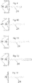
- Figs. 9 to 13 in which cross sections of second through fifth embodiments of posts 22 are depicted.
- the embodiments differ with regard to the length and width of fin 24.
- the depicted embodiments are not exhaustive of the embodiments of the invention that fall within the scope of the invention and are provided for illustrative purposes only.
- ratios of fin length to fin width the depicted figures show a ratios of between 8:1 for Fig 9 and 15:1 for Fig 12 .
- absolute widths and lengths the invention encompasses fins of the following dimensions: 4mm x 60mm, 6mm x 60mm, 6mm x 80mm, 6mm x 100mm, 8mm x 80mm, 8mm x 100mm, 8mm x 120mm.
- a minimum of 300KG can be supported using a 8mm x 80mm sized fin 24.
- the present invention has industrial applicability in the field of retail display shelving for use in displaying and retailing goods including heavy goods.
Landscapes
- Assembled Shelves (AREA)
Priority Applications (3)
| Application Number | Priority Date | Filing Date | Title |
|---|---|---|---|
| EP17150317.0A EP3345512A1 (fr) | 2017-01-04 | 2017-01-04 | Montant de rayonnage et système de rayonnage réglable |
| DE17150317.0T DE17150317T1 (de) | 2017-01-04 | 2017-01-04 | Regalpfosten und verstellbares Regalsystem |
| AU2018200027A AU2018200027B2 (en) | 2017-01-04 | 2018-01-02 | A shelving post and adjustable shelving system |
Applications Claiming Priority (1)
| Application Number | Priority Date | Filing Date | Title |
|---|---|---|---|
| EP17150317.0A EP3345512A1 (fr) | 2017-01-04 | 2017-01-04 | Montant de rayonnage et système de rayonnage réglable |
Publications (1)
| Publication Number | Publication Date |
|---|---|
| EP3345512A1 true EP3345512A1 (fr) | 2018-07-11 |
Family
ID=57714552
Family Applications (1)
| Application Number | Title | Priority Date | Filing Date |
|---|---|---|---|
| EP17150317.0A Withdrawn EP3345512A1 (fr) | 2017-01-04 | 2017-01-04 | Montant de rayonnage et système de rayonnage réglable |
Country Status (2)
| Country | Link |
|---|---|
| EP (1) | EP3345512A1 (fr) |
| DE (1) | DE17150317T1 (fr) |
Citations (2)
| Publication number | Priority date | Publication date | Assignee | Title |
|---|---|---|---|---|
| US5415301A (en) * | 1993-07-26 | 1995-05-16 | Knape & Vogt Canada, Inc. | Structural post member for merchandise display rack |
| NL2006242C2 (nl) * | 2011-02-17 | 2012-08-20 | G H Roelofs Holding B V | Samenstel voor het flexibel en losneembaar vormen van een meubelstuk, eerste koppelelement en staander als onderdeel van het samenstel. |
-
2017
- 2017-01-04 EP EP17150317.0A patent/EP3345512A1/fr not_active Withdrawn
- 2017-01-04 DE DE17150317.0T patent/DE17150317T1/de active Pending
Patent Citations (2)
| Publication number | Priority date | Publication date | Assignee | Title |
|---|---|---|---|---|
| US5415301A (en) * | 1993-07-26 | 1995-05-16 | Knape & Vogt Canada, Inc. | Structural post member for merchandise display rack |
| NL2006242C2 (nl) * | 2011-02-17 | 2012-08-20 | G H Roelofs Holding B V | Samenstel voor het flexibel en losneembaar vormen van een meubelstuk, eerste koppelelement en staander als onderdeel van het samenstel. |
Also Published As
| Publication number | Publication date |
|---|---|
| DE17150317T1 (de) | 2020-01-16 |
Similar Documents
| Publication | Publication Date | Title |
|---|---|---|
| US10681977B2 (en) | Shelving post and an adjustable shelving system | |
| US6015124A (en) | Bracket assembly for carrying signage for a retail display fixture | |
| US5443167A (en) | Merchandising display system | |
| US8959813B2 (en) | Display system including convertible fixture | |
| US7775379B2 (en) | Retail display for greeting cards | |
| US6290077B2 (en) | Display rack with interlocking dividers | |
| US5509541A (en) | Bracket construction | |
| US10945539B2 (en) | Merchandise display fixture | |
| US6786340B2 (en) | Ambidextrous merchandise fixture and method of displaying merchandise therefrom | |
| US9307848B2 (en) | Product display system | |
| US20020027115A1 (en) | Open frame shelf assembly | |
| US20160157636A1 (en) | Signage systems and merchandising display assemblies | |
| US20140374549A1 (en) | Product display system | |
| US8342343B2 (en) | Free-standing, point-of-purchase display | |
| EP4272602B1 (fr) | Système de rayonnage de marchandises de vente au détail et panneaux de pont pour celui-ci | |
| EP3031364B1 (fr) | Dispositif d'affichage de vêtements rabattable | |
| US20040178155A1 (en) | Modular footwear display and storage system and method | |
| US10861355B1 (en) | Rack display | |
| KR200482311Y1 (ko) | 상품 진열대 | |
| US20250176710A1 (en) | Methods and systems for panel rack storage | |
| US20090107936A1 (en) | Display racks and methods of use thereof | |
| US8511485B2 (en) | Modular wave shaped merchandiser rack | |
| AU2018200027B2 (en) | A shelving post and adjustable shelving system | |
| US10687637B2 (en) | Promotion device | |
| US7040495B2 (en) | Point of sale display constructions, systems and methods for consumer products |
Legal Events
| Date | Code | Title | Description |
|---|---|---|---|
| PUAI | Public reference made under article 153(3) epc to a published international application that has entered the european phase |
Free format text: ORIGINAL CODE: 0009012 |
|
| STAA | Information on the status of an ep patent application or granted ep patent |
Free format text: STATUS: THE APPLICATION HAS BEEN PUBLISHED |
|
| AK | Designated contracting states |
Kind code of ref document: A1 Designated state(s): AL AT BE BG CH CY CZ DE DK EE ES FI FR GB GR HR HU IE IS IT LI LT LU LV MC MK MT NL NO PL PT RO RS SE SI SK SM TR |
|
| AX | Request for extension of the european patent |
Extension state: BA ME |
|
| STAA | Information on the status of an ep patent application or granted ep patent |
Free format text: STATUS: REQUEST FOR EXAMINATION WAS MADE |
|
| 17P | Request for examination filed |
Effective date: 20190111 |
|
| RBV | Designated contracting states (corrected) |
Designated state(s): AL AT BE BG CH CY CZ DE DK EE ES FI FR GB GR HR HU IE IS IT LI LT LU LV MC MK MT NL NO PL PT RO RS SE SI SK SM TR |
|
| STAA | Information on the status of an ep patent application or granted ep patent |
Free format text: STATUS: EXAMINATION IS IN PROGRESS |
|
| 17Q | First examination report despatched |
Effective date: 20190404 |
|
| REG | Reference to a national code |
Ref country code: DE Ref legal event code: R210 |
|
| GRAP | Despatch of communication of intention to grant a patent |
Free format text: ORIGINAL CODE: EPIDOSNIGR1 |
|
| STAA | Information on the status of an ep patent application or granted ep patent |
Free format text: STATUS: GRANT OF PATENT IS INTENDED |
|
| INTG | Intention to grant announced |
Effective date: 20200205 |
|
| STAA | Information on the status of an ep patent application or granted ep patent |
Free format text: STATUS: THE APPLICATION IS DEEMED TO BE WITHDRAWN |
|
| 18D | Application deemed to be withdrawn |
Effective date: 20200616 |