EP3345516B1 - Kaffeemaschinensieb und kaffeemaschine - Google Patents
Kaffeemaschinensieb und kaffeemaschine Download PDFInfo
- Publication number
- EP3345516B1 EP3345516B1 EP17828828.8A EP17828828A EP3345516B1 EP 3345516 B1 EP3345516 B1 EP 3345516B1 EP 17828828 A EP17828828 A EP 17828828A EP 3345516 B1 EP3345516 B1 EP 3345516B1
- Authority
- EP
- European Patent Office
- Prior art keywords
- screen body
- screen
- coffee machine
- cavity
- grinding
- Prior art date
- Legal status (The legal status is an assumption and is not a legal conclusion. Google has not performed a legal analysis and makes no representation as to the accuracy of the status listed.)
- Active
Links
Images


Classifications
-
- A—HUMAN NECESSITIES
- A47—FURNITURE; DOMESTIC ARTICLES OR APPLIANCES; COFFEE MILLS; SPICE MILLS; SUCTION CLEANERS IN GENERAL
- A47J—KITCHEN EQUIPMENT; COFFEE MILLS; SPICE MILLS; APPARATUS FOR MAKING BEVERAGES
- A47J31/00—Apparatus for making beverages
- A47J31/06—Filters or strainers for coffee or tea makers ; Holders therefor
-
- A—HUMAN NECESSITIES
- A47—FURNITURE; DOMESTIC ARTICLES OR APPLIANCES; COFFEE MILLS; SPICE MILLS; SUCTION CLEANERS IN GENERAL
- A47J—KITCHEN EQUIPMENT; COFFEE MILLS; SPICE MILLS; APPARATUS FOR MAKING BEVERAGES
- A47J31/00—Apparatus for making beverages
- A47J31/42—Beverage-making apparatus with incorporated grinding or roasting means for coffee
-
- A—HUMAN NECESSITIES
- A47—FURNITURE; DOMESTIC ARTICLES OR APPLIANCES; COFFEE MILLS; SPICE MILLS; SUCTION CLEANERS IN GENERAL
- A47J—KITCHEN EQUIPMENT; COFFEE MILLS; SPICE MILLS; APPARATUS FOR MAKING BEVERAGES
- A47J31/00—Apparatus for making beverages
- A47J31/44—Parts or details or accessories of beverage-making apparatus
- A47J31/4403—Constructional details
Definitions
- the present invention relates to the field of household appliances, and more particularly to a coffee machine screen and a coffee machine.
- a grinding chamber is usually reused as a brewing chamber.
- the grinding chamber is provided with a screen arranged in a cylindrical shape and sleeved at a periphery of the grinding blade set.
- the coffee is stirred usually through the grinding blade set.
- coffee particles will produce centrifugal force, resulting in coarse coffee particles being pushed through the screen. The coarse coffee particles ultimately enter the beverage cup with the coffee liquid. Therefore, the quality of the coffee beverage is reduced.
- US 3 334 574 discloses a coffee maker with a cone-shaped receptacle and an outwardly flaring base.
- the coffee maker includes a cone-shaped receptacle adapted to accommodate a coffee filter.
- FR 1 105 494 describes a filter for a coffee maker that can be placed inside a hole, which is placed above a cup.
- Document CN 204 995 094 describes a filter or filter screen for a coffee or tea maker, wherein the filter unit, filled with tea or coffee, can be placed inside the maker for brewing the beverage.
- the main purpose of the present invention is to provide a coffee machine screen, which restricts the coffee particles from passing through the screen during the stirring of the coffee, thereby improving the quality of the coffee beverage.
- a coffee machine screen provided by the present invention includes the features of claim 1.
- the first screen body and the second screen body are integrated to a whole.
- a material of the first screen body is metallic
- a material of the fixed frame is plastic
- the fixed frame is fixedly connected to the first screen body by injection molding.
- a material of the first screen body is metallic
- a material of the second screen body is plastic
- the second screen body is fixedly connected to the first screen body by injection molding.
- each filter pore of the second screen body includes a straight pore section communicating with an upper surface of the second screen body and a cone pore section communicating with a lower surface of the second screen body, the cone pore section being gradually enlarged towards a direction away from the straight pore section.
- a diameter of a filter pore of the second screen body on an upper surface thereof is in a range of 0.2 mm to 0.8 mm.
- a distance between the inner ring edge and an outer ring edge of the second screen body is in a range of 10 mm to 30 mm.
- the second screen body extends obliquely downwardly or obliquely upwardly in a radially outward direction.
- the second screen body extends obliquely downwardly in the radially outward direction and is inclined at a range of 1° - 10° with respect to a horizontal direction.
- a plurality of hand clasping portions are provided on an inner peripheral surface of an upper portion of the coffee machine screen.
- a mesh range of the first screen body is 80 mesh to 150 mesh.
- the first screen body is gradually enlarged from bottom to top.
- an inclination angle between the first screen body and a vertical direction is in a range of 5° to 30°.
- the first screen body includes a reinforcing rib, the reinforcing rib at least including a reinforcing rib ring in a circumferential direction of the first screen body.
- a lower end of the first screen body is closed.
- the present invention provides a coffee machine, including:
- the outer ring edge of the second screen body includes a mounting flange extending downwardly or upwardly, an outer peripheral surface of the mounting flange being provided with a positioning ring groove for sleevedly positioning a sealing ring, the sealing ring abutting the side wall of the grinding cavity.
- the mounting flange extends downwardly and a lower end of the mounting flange abuts a bottom wall of the grinding cavity.
- the first screen body includes a reinforcing rib
- the reinforcing rib at least includes a reinforcing rib ring in a circumferential direction of the first screen body
- the first screen body comprises an annular region radially corresponding to the grinding blade set, the reinforcing rib ring being provided in the annular region.
- a bottom wall of the cavity is provided with a first boss, the lower end of the first screen body sealingly abutting an upper end face of the first boss, the second screen body being connected to the lower end of the first screen body, the secondary filter cavity being formed between the first screen body and a side wall of the cavity, the beverage cavity being formed between an outer peripheral surface of the first boss and the side wall of the cavity.
- the upper end face of the first boss is provided with a second boss, the first screen body being sleeved at the second boss to be positioned in the grinding cavity.
- the lower end of the first screen body abuts a bottom wall of the cavity, a distance being formed between the lower end of the first screen body and a junction between the second screen body and the first screen body, the secondary filter cavity being formed between a portion of the first screen body above the second screen body and a side wall of the cavity, the beverage cavity being formed between a portion of the first screen body below the second screen body and the side wall of the cavity.
- an upper portion of the coffee machine screen is sealingly connected to the cover; or the upper portion of the coffee machine screen is sealingly connected to the cavity, and the cavity is sealingly connected to the cover.
- the grinding cavity is divided into a primary filter cavity, a secondary filter cavity located on the periphery of the primary filter cavity, and a beverage cavity located below the secondary filter cavity. Therefore, in the process of grinding the coffee beans or stirring the coffee, even if the coarse coffee particles pass through the first screen body into the secondary filter cavity under the action of centrifugal force, the second screen body can also restrict the coarse coffee particles in the secondary filter cavity, thereby effectively avoiding the coarse coffee particles from entering the beverage cavity. Therefore, the quality of coffee beverage will be improved.
- the embodiment of the present invention relates to directional indications (such as upper, lower, left, right, front, rear, ...), the directional indications are only used to interpret the relative positional relationship, the movement, etc., between the components in a particular posture (shown in the accompanying drawings), and the directional indications are changed accordingly if the particular posture changes.
- first, second or the like is included in the embodiments of the present invention, it is used for descriptive purposes only and is not to be construed as an indication or suggestion of its relative importance or implied indications of the number of technical features indicated.
- features defined by “first” or “second” may expressly or implicitly include at least one of the features.
- the present invention provides a coffee machine screen and a coffee machine having the coffee machine screen.
- the coffee machine includes:
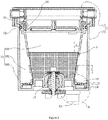
- the first screen body 31 is sleeved at a periphery of the grinding blade set 21 and a lower end of the first screen body 31 is sealingly connected to the bottom of the grinding cavity 10.
- the outer ring edge of the second screen body 32 is sealingly connected to a side wall of the grinding cavity 10.
- a region of the grinding cavity 10 surrounded by the first screen body 31 forms a primary filter cavity 101.
- the second screen body 32 divides the other region of the grinding cavity 10 into a secondary filter cavity 102 above the second screen body 32 and a beverage cavity 103 below the second screen body 32.
- the beverage outlet 13 is communicated with the beverage cavity 103.
- the grinding cavity 10 is divided into a primary filter cavity 101, a secondary filter cavity 102 located on the periphery of the primary filter cavity 101, and a beverage cavity 103 located below the secondary filter cavity 102. Therefore, in the process of grinding the coffee beans or stirring the coffee, even if the coarse coffee particles pass through the first screen body 31 into the secondary filter cavity 102 under the action of centrifugal force, the second screen body 32 can also restrict the coarse coffee particles in the secondary filter cavity 102, thereby effectively avoiding the coarse coffee particles from entering the beverage cavity 103. Therefore, the quality of coffee beverage will be improved.
- the coffee machine screen 3 is used for a coffee machine in which the grinding cavity 10 can be reused as the brewing chamber.
- the coffee machine screen 3 can also be used for a coffee machine having a separate grinding chamber and a separate brewing chamber, and the coffee machine screen 3 can be provided in the brewing chamber.
- the grinding blade set is not provided at the bottom of the brewing chamber, and the lower end of the first screen body 31 can be closed such that the primary filter cavity 101 is absolutely isolated from the beverage cavity 103.
- the first screen body 31 and the second screen body 32 are preferably integrated to a whole. Therefore, the present design can realize the overall assembling, disassembling and cleaning of the coffee machine screen 3, in comparison with the separate arrangement of the two.
- the first screen body 31 and the second screen body 32 may be integrally molded, die-cast or sheet metal parts, etc.
- the materials of the first screen body 31 and the second screen body 32 may be different.
- one of the first screen body 31 and the second screen body 32 is of a metallic material and the other is of a plastic material, and the one with plastic material is fixed to the one with metal material by injection molding.
- the coffee machine screen 3 further includes a fixed frame 33 (see Figure 3 ), and the axial upper end of the first screen body 31 is fixedly connected to the fixed frame 33.
- the upper portion of the coffee machine screen 3 is fixed to the upper portion of the grinding cavity 10 by the fixed frame 33.
- the fixed frame 33 is provided with a structure fixed to the upper portion of the grinding cavity 10 (e.g., but not limited to an abutting flange, a lap flange, etc.), and the addition of the fixed frame 33 avoids the need that a structure which is fixed to the upper portion of the grinding cavity 10 is directly provided at the upper portion of the first screen body 31, thereby simplifying the structure of the first screen body 31 itself.
- the first screen body 31 is of a metallic material to ensure that the rigidity of the first screen body 31 is good.
- the first screen body 31 has good rigidity and can improve the ability of the first screen body 31 for withstanding the outward impact force of coffee beans and coffee particles.
- the first screen body 31 is preferably made of a stainless steel material having a strong rigidity that is more resistant to the outward impact force of the coffee beans and coffee particles.
- the first screen body 31 may be, but is not limited to, made of other metal materials such as aluminum alloy, titanium alloy or the like.
- the fixed frame 33 is of a plastic material, and the fixed frame 33 can be easily fixed to the axial upper end of the first screen body 31 by injection molding.
- the injection molding process is a mature processing technology, which facilitates the batch processing and manufacture of the coffee machine screen 3.
- the fixed frame 33 which is of a plastic material facilitates forming of a structure of the fixed frame 33 which is fixed with the upper portion of the grinding cavity 10.
- the fixed frame 33 may also be fixed to the first screen body 31 by means of bonding or welding.
- the second screen body 32 is also of a plastic material, so that the second screen body 32 can be easily fixed to the axial lower end of the first screen body 31 by injection molding.
- the injection molding process is a mature processing technology, which facilitates the batch processing and manufacture of the coffee machine screen 3.
- the second screen body 32 may also be fixed to the first screen body 31 by means of bonding or welding.
- the second screen body 32 may also be of a metallic material.
- the filter pore 321 on the second screen body 32 is directly injection-molded.
- any filter pore 321 of the second screen body 32 includes a straight pore section 321a communicating with the upper surface thereof and a cone pore section 321b which communicates with the lower surface thereof and is gradually enlarged towards a direction away from the straight pore section 321a.
- the filter pore 321 of the second screen body 32 is connected to the secondary filter cavity 102 through the straight pore section 321a, and to the beverage cavity 103 through the cone pore section 321b.
- the present design is not limited thereto.
- any of the filter pores 321 of the second screen body 32 may also be an integral cone pore which is gradually enlarged towards a direction away from the secondary filter cavity 102.
- the filter pores 321 on the second screen body 32 may also be later perforated and any filter pore 321 may be formed as an integral straight pore.
- the diameter D of the filter pore 321 of the second screen body 32 on the upper surface is preferably in the range of 0.2 mm to 0.8 mm, so that the filter pore 321 of the second screen body 32 is small enough to prevent the coffee grounds from entering the beverage cavity 103 from the secondary filter cavity 102.
- the filter pore 321 of the second screen body 32 may be of a smaller pore size to increase the effect of restricting the coffee grounds.
- the mesh range of the first screen body 31 is preferably in the range of 80 mesh to 150 mesh, and the first screen body 31 under the mesh range has meshes each having a moderate pore size so that when the coffee is brewed, most of coffee grounds is restricted in the primary filter cavity 101.
- the first screen body 31 may also have a smaller mesh range to reduce the cost of the coffee machine screen 3.
- the distance W between the inner ring edge of the second screen body 32 and the outer ring edge is preferably in the range of 10 mm to 30 mm (see Figure 3 ).
- the second screen body 32 extends obliquely downwardly or obliquely upwardly in a radially outward direction so that the coffee grounds, under the action of its own gravity, flows toward the outer ring edge or inner ring edge of the second screen body 32 and is only deposited on the outer ring edge or inner ring edge of the second screen body 32.
- the second screen body 32 since the second screen body 32 is fixed to the lower end of the first screen body 31 by injection molding, the second screen body 32 extends obliquely downwardly in the radially outward direction for ease of demolding.
- the inclination angle of the second screen body 32 can not be too large, otherwise the distance W of the second screen body 32 needs to be large enough to ensure that the space of the secondary filter cavity 102 is not too small. Therefore, the inclination angle ⁇ of the second screen body 32 between the radially outward direction and the horizontal direction is preferably in the range of 1° to 10° (see Figure 2 ).
- the radial dimension of the grinding cavity 10 is adapted to that of the outer ring edge of the second screen body 32. Therefore, the outer ring edge of the second screen body 32 is in tight sealing abutment against the side wall of the grinding cavity 10 so as to sealingly isolate the secondary filter cavity 102 from the beverage cavity 103.
- a first sealing ring (not shown in the Figures) may be added between the outer ring edge of the second screen body 32 and the side wall of the grinding cavity 10.
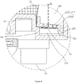
- a mounting flange 322 extending downward or upwardly may be provided at the outer ring edge of the second screen body 32, and the outer peripheral surface of the mounting flange 322 is provided with a positioning ring groove 323 for sleevedly positioning the first sealing ring to position the first sealing ring on the mounting flange 322.
- the first sealing ring portion When the first sealing ring is mounted, the first sealing ring portion partially protrudes from the positioning ring groove 323 and resiliently abuts the side wall of the grinding cavity 10.
- the mounting flange 322 extends downwardly and the lower end of the mounting flange 322 abuts the bottom wall of the grinding cavity 10. Therefore, on the one hand, an additional sealing barrier is provided for the sealing isolation of the secondary filter cavity 102 and the beverage cavity 103; on the other hand, the lower end of the flange 322 can also provide support for the coffee machine screen 3.
- the bottom wall of the cavity 11 is provided with a first boss 14.
- the lower end of the first screen body 31 is in sealing abutment against the upper end face of the first boss 14, and the second screen body 32 is connected to the lower end of the first screen body 31.
- the secondary filter cavity 102 is formed between the first screen body 31 and the side wall of the cavity 11, and the beverage cavity 103 is formed between the outer peripheral surface of the first boss 14 and the cavity 11. It is to be understood that due to the arrangement of the first boss 14, it may be convenient to space the second screen body 32 from the bottom wall of the grinding cavity 10, providing the beverage cavity 103 with a vertical depth.
- the upper end surface of the first boss 14 is preferably provided with a second boss 15 for the first screen body being sleeved at the second boss 15 to be positioned in the grinding cavity 10.
- the first boss 14 may not be provided so that the lower end of the first screen body 31 directly abuts the bottom wall of the cavity 11, but there is a distance formed between the lower end of the first screen body 31 and a junction between the second screen body 32 and the first screen body 31. Therefore, the secondary filter cavity 102 is formed between a portion of the first screen body 31 above the second screen body 32 and the side wall of the cavity 11, and the beverage cavity 103 is formed between a portion of the first screen body 31 below the second screen body 32 and the side wall of the cavity 11. In order to facilitate the positioning of the first screen body 31 and to prevent the first screen body 31 from rocking, the bottom of cavity 11 is still provided with the second boss 15 for the first screen body 31 being sleeved at the second boss 15.
- the first screen body 31 is preferably arranged in a hollow cylindrical shape gradually enlarged from bottom to top. Therefore, the coffee machine screen 3 may have a large upper opening so as to add the coffee beans and hot water to the primary filter cavity 101.
- the inclination angle ⁇ between the first screen body 31 and the vertical direction is preferably in the range of 5° to 30° (see Figure 2 ).
- the first screen body 31 is further provided with a reinforcing rib 311 at least including a reinforcing rib ring 311a provided in the circumferential direction of the first screen body 31, thereby enhancing the rigidity of the first screen body 31 in the circumferential direction to resist the outward impact force of the coffee beans and the coffee particles in order to prevent deformation of the first screen body 31, thus extending the life of the coffee machine screen 3.
- the reinforcing rib 311 further includes a reinforcing rib strip 311b which intersects the reinforcing rib ring 311a.
- the reinforcing rib strip 311b may extend along the axial direction of the first screen body 31, or be inclined with respect to the axial direction of the first screen body 31.
- the upper end of the reinforcing rib strip 311b is preferably fixed to the fixed frame 33 so as to better ensure the rigidity of the first screen body 31.
- the reinforcing rib 311 is also preferably of a plastic material, and thus the reinforcing rib 311 can be easily fixed to the first screen body 31 by injection molding, thereby facilitating batch processing and manufacture of the coffee machine screen 3.
- the fixed frame 33 and the reinforcing rib 311 can be injection molded at one time, and the processing is convenient.
- the first screen body 31 further has an annular region radially corresponding to the grinding blade set 21, and the reinforcing rib ring 311a is provided in the annular region. It will be appreciated that during the grinding of the coffee beans by the grinding blade set 21, the annular regions are subjected to strongest outward impact force from the coffee beans and coffee particles.
- the reinforcing rib ring 311a is purposefully provided in the annular region to directly increase the rigidity of the annular region, and the impact resistance of the coffee machine screen 3 can be more effectively improved.
- the width of the projection of the grinding blade set 21 in the axial direction of the first screen body 31 is approximately 8 mm.
- one reinforcing rib ring 311a is provided in the annular region.
- the width range L of the one reinforcing rib ring 311a is preferably 6 mm to 12 mm (see Figure 2 ).
- the present design is not limited thereto.
- the upper portion of the coffee machine screen 3 is sealingly connected to the cover 12. Therefore, the water inflow rate of the hot water supply device 4 can be adjusted to be greater than the water outflow rate of the coffee machine screen 3.
- a pressure space can be formed in the upper portion of the primary filter cavity 101 to pressure-brewing the coffee so as to sufficiently infiltrate the coffee powder. Therefore, the brewed coffee is stronger.
- the upper portion of the coffee machine screen 3 may be sealingly connected to the cavity 11 and the cavity 11 may be sealingly connected to the cover 12 to form a pressure space in the upper portion of the primary filter cavity 101.
- the cover 12 is provided with a protruding portion 16 extending into the fixed frame 33.
- a second sealing ring 51 is provided between the outer edge of the protruding portion 16 and the inner edge of the fixed frame 33 for realizing a sealing connection between the fixed frame 33 and the protruding portion 16, as shown in Figure 2 .
- a third sealing ring 52 is provided between the outer peripheral surface of the fixed frame 33 and the inner peripheral surface of the upper portion of the cavity 11 for realizing a sealing connection between the upper portion of the coffee machine screen 3 and the cavity 11.
- the upper portion of the coffee machine screen 3 is sealingly connected to the cover 12 so that the grinding cavity 10 is integrally sealed.
- a plurality of hand clasping portions 34 are preferably provided on the upper inner peripheral surface of the coffee machine screen 3 in order to facilitate removal of the coffee machine screen 3 by a user.
- the hand clasping portions 34 are formed on the inner peripheral surface of the fixed frame 33 and in the form of a protrusion.
- the present design is not limited thereto.
- the hand clasping portions 34 may be formed on the fixed frame 33 and in the form of a groove.
- the hand clasping portions 34 may be directly provided on the upper inner peripheral surface of the first screen body 31.
Landscapes
- Engineering & Computer Science (AREA)
- Food Science & Technology (AREA)
- Apparatus For Making Beverages (AREA)
Claims (14)
- Kaffeemaschinensieb (3), umfassend:einen ersten Siebkörper (31), der in einer röhrenförmigen Form angeordnet ist, die sich nach oben und unten erstreckt;einen zweiten Siebkörper (32), der ringförmig angeordnet ist, und eine innere Ringkante des zweiten Siebkörpers (32), die mit einer abdichtenden Verbindung mit einem unteren Bereich des ersten Siebkörpers (31) verbunden ist; undeinen festen Rahmen (33),wobei das Kaffeemaschinensieb dadurch gekennzeichnet ist, dassein axiales oberes Ende des ersten Siebkörpers (31) fest mit dem festen Rahmen (33) verbunden ist.
- Kaffeemaschinensieb (3) gemäß Anspruch 1, wobei der erste Siebkörper (31) und der zweite Siebkörper (32) als eine Einheit integriert sind.
- Kaffeemaschinensieb (3) gemäß Anspruch 1 oder 2, wobei ein Material des ersten Siebkörpers (31) metallisch ist, ein Material des zweiten Siebkörpers (32) aus Kunststoff besteht und der zweite Siebkörper (32) durch Spritzgießen fest mit dem ersten Siebkörper (31) verbunden ist.
- Kaffeemaschinensieb (3) gemäß Anspruch 1, wobei ein Material des ersten Siebkörpers (31) metallisch ist, ein Material des festen Rahmens (33) Kunststoff ist und der feste Rahmen (33) durch Spritzgießen fest mit dem ersten Siebkörper (31) verbunden ist.
- Kaffeemaschinensieb (3) gemäß einem der vorhergehenden Ansprüche, wobei jede Filterpore (321) des zweiten Siebkörpers (32) einen geraden Porenabschnitt (321a), der mit einer oberen Oberfläche des zweiten Siebkörpers (32) in Verbindung steht, und einen Kegelporenabschnitt (321b), der mit einer unteren Oberfläche des zweiten Siebkörpers (32) in Verbindung steht, umfasst, wobei der Kegelporenabschnitt (321b) graduell in Richtung von dem geraden Porenabschnitt (321a) weg vergrößert wird.
- Kaffeemaschinensieb (3) gemäß einem der vorhergehenden Ansprüche, wobei ein Durchmesser einer Filterpore (321) des zweiten Siebkörpers (32) auf einer Oberseite davon in einem Bereich von 0,2 mm bis 0,8 mm liegt.
- Kaffeemaschinensieb (3) gemäß einem der vorhergehenden Ansprüche, wobei sich der zweite Siebkörper (32) schräg nach unten oder schräg nach oben in radial nach außen gerichteter Richtung erstreckt.
- Kaffeemaschinensieb (3) gemäß einem der vorhergehenden Ansprüche, wobei mehrere Handgriffabschnitte (34) an einer inneren Umfangsfläche eines oberen Bereichs des Kaffeemaschinensiebs (3) vorgesehen sind.
- Kaffeemaschinensieb (3) gemäß einem der vorhergehenden Ansprüche, wobei der erste Siebkörper (31) graduell von unten nach oben vergrößert wird.
- Kaffeemaschinensieb (3) gemäß einem der vorhergehenden Ansprüche, wobei der erste Siebkörper (31) eine Verstärkungsrippe (311) umfasst, wobei die Verstärkungsrippe (311) mindestens einen Verstärkungsrippenring (311a) in Umfangsrichtung des ersten Siebkörpers (31) umfasst.
- Kaffeemaschinensieb (3) gemäß einem der vorhergehenden Ansprüche, wobei ein unteres Ende des ersten Siebkörpers (31) geschlossen ist.
- Kaffeemaschine, umfassend:eine Mahlkammer (1) umfassend einen Hohlraum (11) und eine Abdeckung (12), wobei die Abdeckung (12) den Hohlraum (11) umschließt, um einen Mahlhohlraum (10) zu bilden, wobei ein Boden des Mahlhohlraums (10) mit einem Getränkeauslass versehen ist;eine Mahlvorrichtung (2), umfassend einen in dem Mahlhohlraum (10) vorgesehenen Mahlklingensatz (21) und einen außerhalb des Mahlhohlraums (10) vorgesehenen Motor (22) zum Antreiben der Drehung des Mahlklingensatzes (21);eine Heißwasserversorgungsvorrichtung (4) in Verbindung mit dem Mahlhohlraum (10); und das Kaffeemaschinensieb (3) gemäß einem der Ansprüche 1-11.
- Kaffeemaschine gemäß Anspruch 12, wobei die äußere Ringkante des zweiten Siebkörpers (32) einen Montageflansch (322) umfasst, der sich nach unten oder oben erstreckt, wobei eine äußere Umfangsfläche des Montageflansches (322) mit einer Positionierringnut (323) zum hüllenartigen Positionieren eines Dichtungsrings versehen ist, wobei der Dichtungsring an der Seitenwand des Mahlhohlraums (10) anliegt.
- Kaffeemaschine gemäß Anspruch 13, wobei sich der Montageflansch (322) nach unten erstreckt und ein unteres Ende des Montageflansches (322) an einer Bodenwand des Mahlhohlraums (10) anliegt.
Applications Claiming Priority (3)
| Application Number | Priority Date | Filing Date | Title |
|---|---|---|---|
| CN201621096196.XU CN206333757U (zh) | 2016-09-29 | 2016-09-29 | 咖啡机滤网和咖啡机 |
| CN201610867667.0A CN107874621B (zh) | 2016-09-29 | 2016-09-29 | 咖啡机滤网和咖啡机 |
| PCT/CN2017/074234 WO2018058886A1 (zh) | 2016-09-29 | 2017-02-21 | 咖啡机滤网和咖啡机 |
Publications (3)
| Publication Number | Publication Date |
|---|---|
| EP3345516A1 EP3345516A1 (de) | 2018-07-11 |
| EP3345516A4 EP3345516A4 (de) | 2018-09-26 |
| EP3345516B1 true EP3345516B1 (de) | 2020-06-24 |
Family
ID=61763689
Family Applications (1)
| Application Number | Title | Priority Date | Filing Date |
|---|---|---|---|
| EP17828828.8A Active EP3345516B1 (de) | 2016-09-29 | 2017-02-21 | Kaffeemaschinensieb und kaffeemaschine |
Country Status (4)
| Country | Link |
|---|---|
| US (1) | US10806293B2 (de) |
| EP (1) | EP3345516B1 (de) |
| JP (1) | JP6608044B2 (de) |
| WO (1) | WO2018058886A1 (de) |
Families Citing this family (10)
| Publication number | Priority date | Publication date | Assignee | Title |
|---|---|---|---|---|
| US20200359829A1 (en) * | 2017-08-31 | 2020-11-19 | Innovative Brewing, Llc | Devices and methods for brewing beverages |
| CN108579975B (zh) * | 2018-06-28 | 2024-04-23 | 张余超 | 自动搅拌、分渣一体磨浆机 |
| EP3934492A4 (de) * | 2019-03-06 | 2022-11-30 | Innovative Brewing, LLC | Vorrichtungen und verfahren zum brühen von getränken |
| CN110269471B (zh) * | 2019-04-23 | 2020-09-25 | 东阳市川泽户外用品有限公司 | 一种咖啡杯 |
| CN113509060B (zh) * | 2020-04-09 | 2023-03-31 | 漳州灿坤实业有限公司 | 咖啡豆的研磨机构、其待研磨物状况的检测方法及咖啡壶组合 |
| CN111513568A (zh) * | 2020-06-05 | 2020-08-11 | 苏州京竹电器科技有限公司 | 一种便携式奶茶机 |
| DE102020133229A1 (de) * | 2020-12-11 | 2022-06-15 | Pi-Design Ag | Filtervorrichtung zum Filtern von unlöslichem Material |
| CN112710467B (zh) * | 2021-01-27 | 2023-07-18 | 深圳市盈德精密制造有限公司 | 一种咖啡机滤网的生产检测装置 |
| CN215777339U (zh) * | 2021-06-16 | 2022-02-11 | 合一电器(深圳)有限公司 | 具双层滤网的咖啡过滤装置 |
| CN119643127B (zh) * | 2024-12-19 | 2025-09-12 | 广东顺德腾辉电器有限公司 | 一种咖啡机滤网的生产检测装置及方法 |
Family Cites Families (28)
| Publication number | Priority date | Publication date | Assignee | Title |
|---|---|---|---|---|
| FR1105494A (fr) * | 1953-05-15 | 1955-12-05 | Wilh Eichhorn | Filtre pour paquets renfermant une mesure de café ou d'un produit analogue |
| US3334574A (en) * | 1964-06-04 | 1967-08-08 | Douglas David | Cup mounted coffee cones |
| US3592126A (en) * | 1969-12-19 | 1971-07-13 | Gen Electric | Coffeemaker filter |
| JPS55160527A (en) * | 1979-05-30 | 1980-12-13 | Matsushita Electric Industrial Co Ltd | Coffee mill maker |
| JPS5934738U (ja) * | 1982-08-27 | 1984-03-03 | 株式会社東芝 | コ−ヒ−抽出器 |
| US4962693A (en) | 1988-11-02 | 1990-10-16 | Kabushiki Kaisha Toshiba | Centrifugal brewing type coffee maker |
| US4865737A (en) | 1989-01-03 | 1989-09-12 | Mcmichael John R | Filter support for disposable coffee filters |
| US5318703A (en) * | 1993-05-26 | 1994-06-07 | Ultrapure Systems, Inc. | Water filter module |
| DE29504115U1 (de) * | 1995-03-09 | 1996-07-11 | Maxs Ag, Sachseln | Bausatz für einen Filterkaffeebereiter |
| US5865095A (en) * | 1997-03-20 | 1999-02-02 | Conair Corporation | Coffee grinder and maker |
| JPH10275274A (ja) * | 1997-03-28 | 1998-10-13 | Sanyo Electric Co Ltd | 自動販売機 |
| JP3841054B2 (ja) * | 2002-08-08 | 2006-11-01 | 株式会社デンソー | フィルタおよびそれを用いた燃料噴射装置 |
| US20050076784A1 (en) * | 2003-10-10 | 2005-04-14 | Hp Intellectual Corp. | Brewing apparatus pod carrier and frothing attachment |
| US7017472B2 (en) * | 2003-10-10 | 2006-03-28 | Hp Intellectual Corp. | Brewing apparatus water temperature control |
| WO2007041954A1 (en) * | 2005-10-11 | 2007-04-19 | Zhiping Li | Coffee maker |
| CN101161135A (zh) | 2006-10-11 | 2008-04-16 | 马显贵 | 带语音提醒装置的香烟套 |
| CN201147244Y (zh) * | 2007-12-07 | 2008-11-12 | 广东新宝电器股份有限公司 | 全自动豆浆机 |
| AU2011278538B2 (en) * | 2010-07-14 | 2015-04-30 | Ekaterra Research and Development UK Limited | Method for brewing beverage and cartridge containing infusible material |
| CN102058318B (zh) * | 2010-10-29 | 2012-11-21 | 广东新宝电器股份有限公司 | 带磨豆器的滴落式咖啡机 |
| MX341085B (es) * | 2010-12-28 | 2016-08-08 | Starbucks Corp D/B/A Starbucks Coffee Company | Aparato para preparar una bebida y metodo relacionado. |
| CN102551538A (zh) | 2011-12-16 | 2012-07-11 | 周林斌 | 带有磨豆功能的咖啡壶 |
| JP6087614B2 (ja) * | 2012-12-18 | 2017-03-01 | 富士フィルター工業株式会社 | コーヒー抽出器 |
| CN103190832B (zh) | 2013-01-08 | 2015-08-26 | 周林斌 | 一种咖啡壶过滤装置及其方法 |
| US20140245893A1 (en) * | 2013-03-02 | 2014-09-04 | Robert Bao Vu | Methods, apparatus and products for grinding brewable materials into a filter cartridge |
| US9675101B2 (en) * | 2013-03-15 | 2017-06-13 | Whirlpool Corporation | High performance adjustable juicer with whole foods feed chute |
| CN204889459U (zh) * | 2015-06-25 | 2015-12-23 | 浙江武义万家隆塑业有限公司 | 可研磨咖啡豆的咖啡杯 |
| CN204995094U (zh) * | 2015-09-21 | 2016-01-27 | 上海宏晨家庭用品有限公司 | 带有过滤罩和过滤柱的饮料容器 |
| HK1213138A2 (zh) * | 2016-02-03 | 2016-06-24 | 快达实业有限公司 | 一种冷浸泡离心式萃取咖啡机及其方法 |
-
2017
- 2017-02-21 JP JP2018512426A patent/JP6608044B2/ja active Active
- 2017-02-21 EP EP17828828.8A patent/EP3345516B1/de active Active
- 2017-02-21 WO PCT/CN2017/074234 patent/WO2018058886A1/zh not_active Ceased
- 2017-11-27 US US15/822,212 patent/US10806293B2/en active Active
Non-Patent Citations (1)
| Title |
|---|
| None * |
Also Published As
| Publication number | Publication date |
|---|---|
| US10806293B2 (en) | 2020-10-20 |
| JP2018531657A (ja) | 2018-11-01 |
| JP6608044B2 (ja) | 2019-11-20 |
| EP3345516A1 (de) | 2018-07-11 |
| WO2018058886A1 (zh) | 2018-04-05 |
| EP3345516A4 (de) | 2018-09-26 |
| US20180084939A1 (en) | 2018-03-29 |
Similar Documents
| Publication | Publication Date | Title |
|---|---|---|
| EP3345516B1 (de) | Kaffeemaschinensieb und kaffeemaschine | |
| JP4378544B2 (ja) | 洗浄容易な多機能豆乳機 | |
| CN107874621B (zh) | 咖啡机滤网和咖啡机 | |
| RU2604177C2 (ru) | Улучшения, касающиеся машин для приготовления напитков | |
| US20160255987A1 (en) | Adapter for use in a coffee machine | |
| CN107811514B (zh) | 咖啡机 | |
| EP3513689B1 (de) | Kaffeemaschine und herstellungsverfahren dafür | |
| US7234390B2 (en) | Holder for coffee pod | |
| CN112493888B (zh) | 一种宽容量的食品加工机 | |
| EP1753328B1 (de) | Vorrichtung zur herstellung einer brühe aus einer aromatischen gemüsesubstanz und patrone mit der aromatischen gemüsesubstanz | |
| CN100542463C (zh) | 饮料制造设备 | |
| CN206284884U (zh) | 咖啡机 | |
| CN107811511B (zh) | 咖啡机 | |
| CN206284885U (zh) | 咖啡机 | |
| CN206333757U (zh) | 咖啡机滤网和咖啡机 | |
| CN214128335U (zh) | 一种工作稳定的多功能食品加工机 | |
| EP2555662B1 (de) | Doppelfunktionsanschlussstück für einen geschirrspüler | |
| CN210697360U (zh) | 一种料理机 | |
| NL2038314B1 (en) | Beverage capsule with elevated dome shaped needle penetration region | |
| CN213371443U (zh) | 一种多功能煮茶壶 | |
| CN218355720U (zh) | 一种液体加热容器及液体加热装置 | |
| CN210541099U (zh) | 一种操作便捷的食品加工机 | |
| WO2026021988A1 (en) | Beverage capsule with elevated dome shaped needle penetration region | |
| CN209031927U (zh) | 一种胶囊咖啡机用过滤胶囊杯 | |
| JPS6310121Y2 (de) |
Legal Events
| Date | Code | Title | Description |
|---|---|---|---|
| STAA | Information on the status of an ep patent application or granted ep patent |
Free format text: STATUS: UNKNOWN |
|
| STAA | Information on the status of an ep patent application or granted ep patent |
Free format text: STATUS: THE INTERNATIONAL PUBLICATION HAS BEEN MADE |
|
| PUAI | Public reference made under article 153(3) epc to a published international application that has entered the european phase |
Free format text: ORIGINAL CODE: 0009012 |
|
| STAA | Information on the status of an ep patent application or granted ep patent |
Free format text: STATUS: REQUEST FOR EXAMINATION WAS MADE |
|
| 17P | Request for examination filed |
Effective date: 20180123 |
|
| AK | Designated contracting states |
Kind code of ref document: A1 Designated state(s): AL AT BE BG CH CY CZ DE DK EE ES FI FR GB GR HR HU IE IS IT LI LT LU LV MC MK MT NL NO PL PT RO RS SE SI SK SM TR |
|
| AX | Request for extension of the european patent |
Extension state: BA ME |
|
| RIC1 | Information provided on ipc code assigned before grant |
Ipc: A47J 31/42 20060101ALI20180816BHEP Ipc: A47J 31/06 20060101AFI20180816BHEP |
|
| A4 | Supplementary search report drawn up and despatched |
Effective date: 20180823 |
|
| DAV | Request for validation of the european patent (deleted) | ||
| DAX | Request for extension of the european patent (deleted) | ||
| GRAP | Despatch of communication of intention to grant a patent |
Free format text: ORIGINAL CODE: EPIDOSNIGR1 |
|
| STAA | Information on the status of an ep patent application or granted ep patent |
Free format text: STATUS: GRANT OF PATENT IS INTENDED |
|
| INTG | Intention to grant announced |
Effective date: 20200117 |
|
| GRAS | Grant fee paid |
Free format text: ORIGINAL CODE: EPIDOSNIGR3 |
|
| GRAA | (expected) grant |
Free format text: ORIGINAL CODE: 0009210 |
|
| STAA | Information on the status of an ep patent application or granted ep patent |
Free format text: STATUS: THE PATENT HAS BEEN GRANTED |
|
| AK | Designated contracting states |
Kind code of ref document: B1 Designated state(s): AL AT BE BG CH CY CZ DE DK EE ES FI FR GB GR HR HU IE IS IT LI LT LU LV MC MK MT NL NO PL PT RO RS SE SI SK SM TR |
|
| REG | Reference to a national code |
Ref country code: GB Ref legal event code: FG4D |
|
| REG | Reference to a national code |
Ref country code: CH Ref legal event code: EP |
|
| REG | Reference to a national code |
Ref country code: AT Ref legal event code: REF Ref document number: 1283024 Country of ref document: AT Kind code of ref document: T Effective date: 20200715 |
|
| REG | Reference to a national code |
Ref country code: DE Ref legal event code: R096 Ref document number: 602017018837 Country of ref document: DE |
|
| REG | Reference to a national code |
Ref country code: IE Ref legal event code: FG4D |
|
| PG25 | Lapsed in a contracting state [announced via postgrant information from national office to epo] |
Ref country code: LT Free format text: LAPSE BECAUSE OF FAILURE TO SUBMIT A TRANSLATION OF THE DESCRIPTION OR TO PAY THE FEE WITHIN THE PRESCRIBED TIME-LIMIT Effective date: 20200624 Ref country code: FI Free format text: LAPSE BECAUSE OF FAILURE TO SUBMIT A TRANSLATION OF THE DESCRIPTION OR TO PAY THE FEE WITHIN THE PRESCRIBED TIME-LIMIT Effective date: 20200624 Ref country code: GR Free format text: LAPSE BECAUSE OF FAILURE TO SUBMIT A TRANSLATION OF THE DESCRIPTION OR TO PAY THE FEE WITHIN THE PRESCRIBED TIME-LIMIT Effective date: 20200925 Ref country code: NO Free format text: LAPSE BECAUSE OF FAILURE TO SUBMIT A TRANSLATION OF THE DESCRIPTION OR TO PAY THE FEE WITHIN THE PRESCRIBED TIME-LIMIT Effective date: 20200924 Ref country code: SE Free format text: LAPSE BECAUSE OF FAILURE TO SUBMIT A TRANSLATION OF THE DESCRIPTION OR TO PAY THE FEE WITHIN THE PRESCRIBED TIME-LIMIT Effective date: 20200624 |
|
| REG | Reference to a national code |
Ref country code: LT Ref legal event code: MG4D |
|
| PG25 | Lapsed in a contracting state [announced via postgrant information from national office to epo] |
Ref country code: BG Free format text: LAPSE BECAUSE OF FAILURE TO SUBMIT A TRANSLATION OF THE DESCRIPTION OR TO PAY THE FEE WITHIN THE PRESCRIBED TIME-LIMIT Effective date: 20200924 Ref country code: RS Free format text: LAPSE BECAUSE OF FAILURE TO SUBMIT A TRANSLATION OF THE DESCRIPTION OR TO PAY THE FEE WITHIN THE PRESCRIBED TIME-LIMIT Effective date: 20200624 Ref country code: HR Free format text: LAPSE BECAUSE OF FAILURE TO SUBMIT A TRANSLATION OF THE DESCRIPTION OR TO PAY THE FEE WITHIN THE PRESCRIBED TIME-LIMIT Effective date: 20200624 Ref country code: LV Free format text: LAPSE BECAUSE OF FAILURE TO SUBMIT A TRANSLATION OF THE DESCRIPTION OR TO PAY THE FEE WITHIN THE PRESCRIBED TIME-LIMIT Effective date: 20200624 |
|
| REG | Reference to a national code |
Ref country code: NL Ref legal event code: MP Effective date: 20200624 |
|
| REG | Reference to a national code |
Ref country code: AT Ref legal event code: MK05 Ref document number: 1283024 Country of ref document: AT Kind code of ref document: T Effective date: 20200624 |
|
| PG25 | Lapsed in a contracting state [announced via postgrant information from national office to epo] |
Ref country code: AL Free format text: LAPSE BECAUSE OF FAILURE TO SUBMIT A TRANSLATION OF THE DESCRIPTION OR TO PAY THE FEE WITHIN THE PRESCRIBED TIME-LIMIT Effective date: 20200624 Ref country code: NL Free format text: LAPSE BECAUSE OF FAILURE TO SUBMIT A TRANSLATION OF THE DESCRIPTION OR TO PAY THE FEE WITHIN THE PRESCRIBED TIME-LIMIT Effective date: 20200624 |
|
| PG25 | Lapsed in a contracting state [announced via postgrant information from national office to epo] |
Ref country code: RO Free format text: LAPSE BECAUSE OF FAILURE TO SUBMIT A TRANSLATION OF THE DESCRIPTION OR TO PAY THE FEE WITHIN THE PRESCRIBED TIME-LIMIT Effective date: 20200624 Ref country code: CZ Free format text: LAPSE BECAUSE OF FAILURE TO SUBMIT A TRANSLATION OF THE DESCRIPTION OR TO PAY THE FEE WITHIN THE PRESCRIBED TIME-LIMIT Effective date: 20200624 Ref country code: AT Free format text: LAPSE BECAUSE OF FAILURE TO SUBMIT A TRANSLATION OF THE DESCRIPTION OR TO PAY THE FEE WITHIN THE PRESCRIBED TIME-LIMIT Effective date: 20200624 Ref country code: ES Free format text: LAPSE BECAUSE OF FAILURE TO SUBMIT A TRANSLATION OF THE DESCRIPTION OR TO PAY THE FEE WITHIN THE PRESCRIBED TIME-LIMIT Effective date: 20200624 Ref country code: PT Free format text: LAPSE BECAUSE OF FAILURE TO SUBMIT A TRANSLATION OF THE DESCRIPTION OR TO PAY THE FEE WITHIN THE PRESCRIBED TIME-LIMIT Effective date: 20201026 Ref country code: IT Free format text: LAPSE BECAUSE OF FAILURE TO SUBMIT A TRANSLATION OF THE DESCRIPTION OR TO PAY THE FEE WITHIN THE PRESCRIBED TIME-LIMIT Effective date: 20200624 Ref country code: SM Free format text: LAPSE BECAUSE OF FAILURE TO SUBMIT A TRANSLATION OF THE DESCRIPTION OR TO PAY THE FEE WITHIN THE PRESCRIBED TIME-LIMIT Effective date: 20200624 Ref country code: EE Free format text: LAPSE BECAUSE OF FAILURE TO SUBMIT A TRANSLATION OF THE DESCRIPTION OR TO PAY THE FEE WITHIN THE PRESCRIBED TIME-LIMIT Effective date: 20200624 |
|
| PG25 | Lapsed in a contracting state [announced via postgrant information from national office to epo] |
Ref country code: IS Free format text: LAPSE BECAUSE OF FAILURE TO SUBMIT A TRANSLATION OF THE DESCRIPTION OR TO PAY THE FEE WITHIN THE PRESCRIBED TIME-LIMIT Effective date: 20201024 Ref country code: SK Free format text: LAPSE BECAUSE OF FAILURE TO SUBMIT A TRANSLATION OF THE DESCRIPTION OR TO PAY THE FEE WITHIN THE PRESCRIBED TIME-LIMIT Effective date: 20200624 Ref country code: PL Free format text: LAPSE BECAUSE OF FAILURE TO SUBMIT A TRANSLATION OF THE DESCRIPTION OR TO PAY THE FEE WITHIN THE PRESCRIBED TIME-LIMIT Effective date: 20200624 |
|
| REG | Reference to a national code |
Ref country code: DE Ref legal event code: R097 Ref document number: 602017018837 Country of ref document: DE |
|
| PG25 | Lapsed in a contracting state [announced via postgrant information from national office to epo] |
Ref country code: DK Free format text: LAPSE BECAUSE OF FAILURE TO SUBMIT A TRANSLATION OF THE DESCRIPTION OR TO PAY THE FEE WITHIN THE PRESCRIBED TIME-LIMIT Effective date: 20200624 |
|
| PLBE | No opposition filed within time limit |
Free format text: ORIGINAL CODE: 0009261 |
|
| STAA | Information on the status of an ep patent application or granted ep patent |
Free format text: STATUS: NO OPPOSITION FILED WITHIN TIME LIMIT |
|
| 26N | No opposition filed |
Effective date: 20210325 |
|
| PG25 | Lapsed in a contracting state [announced via postgrant information from national office to epo] |
Ref country code: SI Free format text: LAPSE BECAUSE OF FAILURE TO SUBMIT A TRANSLATION OF THE DESCRIPTION OR TO PAY THE FEE WITHIN THE PRESCRIBED TIME-LIMIT Effective date: 20200624 |
|
| PG25 | Lapsed in a contracting state [announced via postgrant information from national office to epo] |
Ref country code: MC Free format text: LAPSE BECAUSE OF FAILURE TO SUBMIT A TRANSLATION OF THE DESCRIPTION OR TO PAY THE FEE WITHIN THE PRESCRIBED TIME-LIMIT Effective date: 20200624 |
|
| REG | Reference to a national code |
Ref country code: BE Ref legal event code: MM Effective date: 20210228 |
|
| PG25 | Lapsed in a contracting state [announced via postgrant information from national office to epo] |
Ref country code: CH Free format text: LAPSE BECAUSE OF NON-PAYMENT OF DUE FEES Effective date: 20210228 Ref country code: LU Free format text: LAPSE BECAUSE OF NON-PAYMENT OF DUE FEES Effective date: 20210221 Ref country code: LI Free format text: LAPSE BECAUSE OF NON-PAYMENT OF DUE FEES Effective date: 20210228 |
|
| PG25 | Lapsed in a contracting state [announced via postgrant information from national office to epo] |
Ref country code: IE Free format text: LAPSE BECAUSE OF NON-PAYMENT OF DUE FEES Effective date: 20210221 |
|
| PG25 | Lapsed in a contracting state [announced via postgrant information from national office to epo] |
Ref country code: BE Free format text: LAPSE BECAUSE OF NON-PAYMENT OF DUE FEES Effective date: 20210228 |
|
| PG25 | Lapsed in a contracting state [announced via postgrant information from national office to epo] |
Ref country code: CY Free format text: LAPSE BECAUSE OF FAILURE TO SUBMIT A TRANSLATION OF THE DESCRIPTION OR TO PAY THE FEE WITHIN THE PRESCRIBED TIME-LIMIT Effective date: 20200624 |
|
| PG25 | Lapsed in a contracting state [announced via postgrant information from national office to epo] |
Ref country code: HU Free format text: LAPSE BECAUSE OF FAILURE TO SUBMIT A TRANSLATION OF THE DESCRIPTION OR TO PAY THE FEE WITHIN THE PRESCRIBED TIME-LIMIT; INVALID AB INITIO Effective date: 20170221 |
|
| PG25 | Lapsed in a contracting state [announced via postgrant information from national office to epo] |
Ref country code: MK Free format text: LAPSE BECAUSE OF FAILURE TO SUBMIT A TRANSLATION OF THE DESCRIPTION OR TO PAY THE FEE WITHIN THE PRESCRIBED TIME-LIMIT Effective date: 20200624 |
|
| PG25 | Lapsed in a contracting state [announced via postgrant information from national office to epo] |
Ref country code: TR Free format text: LAPSE BECAUSE OF FAILURE TO SUBMIT A TRANSLATION OF THE DESCRIPTION OR TO PAY THE FEE WITHIN THE PRESCRIBED TIME-LIMIT Effective date: 20200624 |
|
| PG25 | Lapsed in a contracting state [announced via postgrant information from national office to epo] |
Ref country code: MT Free format text: LAPSE BECAUSE OF FAILURE TO SUBMIT A TRANSLATION OF THE DESCRIPTION OR TO PAY THE FEE WITHIN THE PRESCRIBED TIME-LIMIT Effective date: 20200624 |
|
| PGFP | Annual fee paid to national office [announced via postgrant information from national office to epo] |
Ref country code: DE Payment date: 20250219 Year of fee payment: 9 |
|
| PGFP | Annual fee paid to national office [announced via postgrant information from national office to epo] |
Ref country code: FR Payment date: 20250220 Year of fee payment: 9 |
|
| PGFP | Annual fee paid to national office [announced via postgrant information from national office to epo] |
Ref country code: GB Payment date: 20250219 Year of fee payment: 9 |